EP0572934A1 - Organ cavity introduction duct - Google Patents
Organ cavity introduction duct Download PDFInfo
- Publication number
- EP0572934A1 EP0572934A1 EP93108640A EP93108640A EP0572934A1 EP 0572934 A1 EP0572934 A1 EP 0572934A1 EP 93108640 A EP93108640 A EP 93108640A EP 93108640 A EP93108640 A EP 93108640A EP 0572934 A1 EP0572934 A1 EP 0572934A1
- Authority
- EP
- European Patent Office
- Prior art keywords
- line
- mouth
- hollow organ
- thread
- perforation
- Prior art date
- Legal status (The legal status is an assumption and is not a legal conclusion. Google has not performed a legal analysis and makes no representation as to the accuracy of the status listed.)
- Withdrawn
Links
Images
Classifications
-
- A—HUMAN NECESSITIES
- A61—MEDICAL OR VETERINARY SCIENCE; HYGIENE
- A61M—DEVICES FOR INTRODUCING MEDIA INTO, OR ONTO, THE BODY; DEVICES FOR TRANSDUCING BODY MEDIA OR FOR TAKING MEDIA FROM THE BODY; DEVICES FOR PRODUCING OR ENDING SLEEP OR STUPOR
- A61M25/00—Catheters; Hollow probes
- A61M25/01—Introducing, guiding, advancing, emplacing or holding catheters
- A61M25/02—Holding devices, e.g. on the body
- A61M25/04—Holding devices, e.g. on the body in the body, e.g. expansible
Definitions
- the invention relates to a line with an internal longitudinal cavity, in particular a hose, for insertion into a hollow organ, for example into a blood vessel, into the bladder or the like, a predetermined distance being provided between the mouth of the line and its entry into the hollow organ in the position of use.
- a tube should be able to be inserted into a hollow organ with a precisely defined depth if it is required as an infusion tube and insertion too deep could mean the risk of perforation, for example in the heart area. Conversely, the insertion depth must not be too small.
- the line has an opening approximately at the predetermined distance from its mouth, and that an axial element is provided for axially fixing the line in the inlet, which is supported through the opening in the hollow organ and through a axial relative movement between the line and the elastic element releases the line relative to the hollow organ again.
- the line has at least one lateral perforation or opening at about the distance from its mouth, in which it projects into the hollow organ in the position of use, and that a U-shaped one in the region of the mouth of the line for fixing the line curved thread Spring-elastic material is provided, which exits with a holding end through the lateral perforation, is held together by the region of the line lying between this perforation and the mouth and is located in a U-shaped or V-shaped manner and with the other end to the region of the line located outside the hollow organ survives.
- This anchoring arrangement thus allows anchoring a line or a hose in a hollow organ with a predetermined depth, so that on the one hand when using the hose as Insert the infusion tube too deeply and thus avoid the risk of perforations in the heart area or the tube can be used as a measuring device, for example to determine the distance of the hollow organ or blood vessel from the skin surface, without there being any disadvantageous measurement errors.
- the determination of the distance of the hollow organ under the surface of the skin is important when an artery has to be closed again after a puncture and a collagen closure is to be brought to the opening of the artery.
- the collagen must be deposited at a precisely defined depth under the skin above the artery, so that it does not get into the artery and creates the risk of vascular occlusion or, due to the distance from the artery, does not have any occlusive effect.
- An improvement in the anchoring can be that the thread runs twice over its length and outside the line and the lateral perforation and is bent or kinked in particular in a U or V shape at its holding end.
- the thread runs twice over its length and outside the line and the lateral perforation and is bent or kinked in particular in a U or V shape at its holding end.
- the holding end is smooth due to the double-ply and the bending or kinking provided there and cannot drill into the inner wall of the vessel.
- lateral perforations can be provided at different distances from the mouth.
- surgeon can choose beforehand how deep the line should protrude into a hollow organ by letting the anchoring thread and its anchoring end emerge from a corresponding lateral perforation.
- a plurality of lateral perforations are distributed around the circumference at approximately the same distance and / or are provided at different distances from the mouth.
- the line designed according to the invention can be introduced with the correspondingly prepared thread in a known manner through a guide set or a guide sleeve into an artery, after which the guide set is removed while the line or the tube, preferably a catheter, due to the holding end of the anchoring thread in the Artery gets stuck.
- the line can be marked on the outside or carry a length marking.
- This has the advantage that an insertion sleeve for collagen can be pushed forwards to close the puncture opening on the blood vessel until it ends shortly before the entrance into the artery.
- the elastic, but inherently stiff thread for example a nylon thread, can be withdrawn until its holding end extends in a straight line to the opposite end, after which the thread can be advanced into the artery.
- the line, the tube or catheter can be removed and the closure plug made of collagen material can now be passed through the insertion sleeve over the thread up to the artery opening.
- a wire inserted into the insertion sleeve can also be used.
- the line can contain several anchoring threads, of which a holding end can emerge through the same or different lateral perforations.
- the anchoring can be improved accordingly.
- a further embodiment of the line of very significant importance can provide from the outset a seal of its entry area with respect to the passage into the hollow organ and be characterized in that the inside of the line contains a detachably or removably arranged balloon catheter, the balloon area of which, in the position of use, at least partially from the emerges from the mouth located in the hollow organ. If the balloon is expanded in this position, it seals the puncture site in the blood vessel from the inside and thus prevents the inflow of blood until, for example, the aforementioned collagen closure is set, without the artery having to be closed by pressing during the attachment of the collagen closure. Such a pressing of the artery is in fact uncomfortable and can shift the tissue in the operating area so that a previously measured depth may no longer be applicable.
- the collagen closure can be placed at the most convenient location without any problems and without the disadvantages described.
- the collagen closure can initially be designed in a tubular manner in a known manner and, as already described in the previous exemplary embodiment, can be threaded and fed in via the catheter feed.
- 1 to 4 show a line 1 with an internal longitudinal cavity 2, for example a hose or a catheter, with regard to its anchoring in a blood vessel 3.
- Special application examples and configurations of this arrangement are in two embodiments, namely an embodiment according to 5 to 9 and a further embodiment according to Fig. 10 to 14 explained in more detail below.
- Matching parts receive matching reference numbers even with different designs.
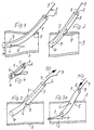
- FIGS. 2, 7 and 8, and 11 and 12 It can be seen from FIGS. 2, 7 and 8, and 11 and 12 that a predetermined distance is provided between the mouth 4 of the line 1 and its entry 5 into the blood vessel 3. This is achieved in that the line 1 at this distance from its mouth 4 has a lateral perforation 6 or opening and that to fix the line 1 in the desired position a U-shaped thread 7 made of resilient material in the area of the mouth 4, it is therefore provided with a certain inherent rigidity which emerges through the lateral perforation 6 with a holding end 8.
- This thread 7 is held together by the area of the line 1 lying between the perforation 6 and the mouth 4 in its U-shaped or V-shaped position, so that the emerging holding end in the area of the perforation is first deflected against the direction in which a tensile load is applied could occur on line 1.
- the other end 9 of the thread protrudes from the area of line 1 located outside the blood vessel, so that according to.
- the thread 7 can first be displaced inward according to the arrow Pf2 to release it from its holding position until the holding end 8 has left the perforation 6 and expediently also the mouth 4 of the line 1; then the line 1 can be withdrawn and the thread 7 can still be used as a guide or the thread 7 can be withdrawn.
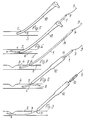
- FIG. 7 shows a known cutlery 10 through which according to. 6 the line 1, which is designed as a catheter in this case, is inserted with the thread loop.
- the line 1 or the catheter according to FIG. 7 gets stuck in the blood vessel 3 because the holding end 8 of the thread 7 lies against the inside of the blood vessel 3.
- the catheter or line 1 has a length marking 11. If such a marking 11 is not present from the outset, it could also be applied by the surgeon in the area which, in the position of use, lies approximately at the passage of the line 1 through the skin surface.
- This length marking 11 allows acc. 8 the pushing on of an insertion sleeve 12 until its mouth is shortly before the entry 5 into the blood vessel 3.
- a closure plug 13 can be guided over the thread 7 still protruding into the blood vessel 3 and somewhat inserted therein or an additional wire that can be inserted through the line 7 until it enters the blood vessel 3.
- the puncture opening serving as entry 5 for example an artery, can be securely closed, as is also shown in FIG. 14.
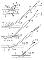
- a line 1 or a catheter with a seal of the entry area with respect to the entry 5 into the blood vessel 3 is shown.
- the line 1 is in turn inserted into the blood vessel 3 with a guide set 10.
- a detachable or removable balloon catheter 15a In the interior of the line 1 there is a detachable or removable balloon catheter 15a, the balloon 15 of which at least partially emerges from the mouth 4 located in the hollow organ or the blood vessel 3 in the position of use.
- the balloon 15 can, according to FIG. 11 are unfolded upstream and thus prevent the blood supply to the inlet 5 until a collagen closure 13 is arranged there.
- the insertion of the collagen plug 13 corresponds to Fig. 13 the mode of operation already shown in Fig. 9.
- a length marking 11 can also be 11 may be present.
- Fig.12 it is shown that the balloon 15 can also be unfolded immediately below the inlet 5 and at the mouth 4 of the line 1 in order to produce a temporary seal at this point until the collagen closure 13 after being pushed over the balloon catheter in accordance with .
- Fig. 14 has reached its position of use. After deflating the balloon 15, it can then be gem. the arrow Pf 3 in Fig. 14 are withdrawn through the tube-shaped collagen closure 13, after which the collagen automatically becomes a sealing closure in a known manner.
- the thread 7 is curved in a U-shape in the region of the mouth 4, that is to say in the insertion direction behind the perforation 6 or in the region between this perforation 6 and the mouth 4, and exits with a holding end 8 through the lateral perforation 6.
- the area of the line 1 lying between the perforation 6 and the mouth 4 is held together in its U-shaped or V-shaped position, the actual curvature possibly even being in front of or outside the mouth 4.
- the other end 9 of the thread 7 opposite the holding end 8 protrudes from the area of the line 1 located outside the hollow organ, so that to release the anchoring at this end 9 it can be pulled until the U-shaped or V-shaped loop is released and the holding end 8 are withdrawn.
- the thread can also lie twice and be bent over at its holding end 8, so that two loop-shaped layers result in the mouth region.
Landscapes
- Health & Medical Sciences (AREA)
- Life Sciences & Earth Sciences (AREA)
- Biophysics (AREA)
- Pulmonology (AREA)
- Engineering & Computer Science (AREA)
- Anesthesiology (AREA)
- Biomedical Technology (AREA)
- Heart & Thoracic Surgery (AREA)
- Hematology (AREA)
- Animal Behavior & Ethology (AREA)
- General Health & Medical Sciences (AREA)
- Public Health (AREA)
- Veterinary Medicine (AREA)
- Media Introduction/Drainage Providing Device (AREA)
Abstract
Description
Die Erfindung betrifft eine Leitung mit einer Innenlängshöhlung, insbesondere Schlauch, zum Einführen in ein Hohlorgan, zum Beispiel in ein Blutgefäß, in die Harnblase oder dergleichen, wobei zwischen der Mündung der Leitung und ihrem Eintritt in das Hohlorgan in Gebrauchsstellung ein vorbestimmter Abstand vorgesehen ist.The invention relates to a line with an internal longitudinal cavity, in particular a hose, for insertion into a hollow organ, for example into a blood vessel, into the bladder or the like, a predetermined distance being provided between the mouth of the line and its entry into the hollow organ in the position of use.
Es ist bereits bekannt, den Schlauch eines Blasenkatheters mit seiner Mündung im Inneren der Blase mit Hilfe eines Federelementes zu verankern, welches während der Einführung durch den Harnleiter durch dessen Wandungen zusammengedrückt wird und sich nach Verlassen des Harnleiters in der Blase aufgrund der Federwirkung aufspreizt. Zum Zurückziehen ist ein entsprechendes Werkzeug, zum Beispiel ein spezieller Mandrin erforderlich, mit welchem die Federwirkung und die Aufspreizung rückgängig gemacht werden können.It is already known to anchor the tube of a bladder catheter with its mouth inside the bladder with the aid of a spring element which is compressed by the walls of the ureter during insertion and which spreads out in the bladder after leaving the ureter due to the spring action. A suitable tool is required for retraction, for example a special stylet, with which the spring action and the expansion can be reversed.
Häufig ist es jedoch erforderlich, eine Leitung oder einen Schlauch durch eine künstliche Öffnung in ein Hohlorgan einzuführen und die Leitung zu verankern. Vor allem bei Blutgefäßen ist dies ein häufiger Vorgang. Dabei sind Einführbestecke bekannt, die nach dem Punktieren mit einer Kanüle über diese geschoben werden und dann auch die Öffnung in dem Blutgefäß abdichten. Durch derartige zu dem Einführbesteck gehörende Einführhülsen können Katheter oder ein festzulegender Schlauch in das Blutgefäß eingeführt werden.However, it is often necessary to insert a line or a hose through an artificial opening into a hollow organ and to anchor the line. This is a common process, especially with blood vessels. Introducers are known which, after puncturing, are pushed over a cannula and then also seal the opening in the blood vessel. Such insertion sleeves belonging to the insertion set can be used to insert catheters or a tube to be fixed into the blood vessel.
Dabei ist es wünschenswert, die Einführtiefe in definierter und bekannter Weise festzulegen und den eingeführten Schlauch zugfest aber lösbar zu verankern. Beispielsweise soll ein Schlauch in ein Hohlorgan mit genau definierter Tiefe eingeführt werden können, wenn er als Infusionsschlauch benötigt wird und ein zu tiefes Einschieben die Gefahr einer Perforation zum Beispiel im Herzbereich bedeuten könnte. Umgekehrt darf jedoch auch die Einführtiefe nicht zu gering sein.It is desirable to define the insertion depth in a defined and known manner and to anchor the inserted hose in a tensile but detachable manner. For example, a tube should be able to be inserted into a hollow organ with a precisely defined depth if it is required as an infusion tube and insertion too deep could mean the risk of perforation, for example in the heart area. Conversely, the insertion depth must not be too small.
Es besteht deshalb die Aufgabe, eine Leitung der eingangs erwähnten Art zu schaffen, die in ein Hohlorgan einführbar und dort lösbar verankerbar ist, aber auch leicht wieder zurückgezogen werden kann, ohne daß ein besonderes Werkzeug oder ein Mandrin erforderlich sind. Dabei soll eine definierte Einführtiefe fixiert werden können.It is therefore the task of creating a line of the type mentioned in the introduction, which can be inserted into a hollow organ and releasably anchored there, but can also be easily withdrawn again without the need for a special tool or stylet. It should be possible to fix a defined insertion depth.
Die Lösung dieser Aufgabe besteht darin, daß die Leitung etwa in dem vorbestimmten Abstand von ihrer Mündung eine Öffnung hat, und daß zum axialen Fixieren der Leitung im Eintritt ein elastisches Element vorgesehen ist, das durch die Öffnung hindurch sich im Hohlorgan abstützt und das durch eine axiale Relativbewegung zwischen Leitung und elastischem Element die Leitung gegenüber dem Hohlorgan wieder freigibt.The solution to this problem is that the line has an opening approximately at the predetermined distance from its mouth, and that an axial element is provided for axially fixing the line in the inlet, which is supported through the opening in the hollow organ and through a axial relative movement between the line and the elastic element releases the line relative to the hollow organ again.
Besonders zweckmäßig ist es dabei, wenn die Leitung etwa in dem Abstand von ihrer Mündung, in dem sie in Gebrauchsstellung in das Hohlorgan ragt, wenigstens eine seitliche Lochung oder Öffnung hat und daß zum Fixieren der Leitung ein im Bereich der Mündung der Leitung U-förmig gekrümmter Faden aus federelastischem Werkstoff vorgesehen ist, der mit einem Halteende durch die seitliche Lochung austritt, von dem zwischen dieser Lochung und der Mündung liegenden Bereich der Leitung U- oder V-förmig liegend zusammengehalten ist und mit dem anderen Ende an dem außerhalb des Hohlorganes befindlichen Bereich der Leitung übersteht.It is particularly expedient if the line has at least one lateral perforation or opening at about the distance from its mouth, in which it projects into the hollow organ in the position of use, and that a U-shaped one in the region of the mouth of the line for fixing the line curved thread Spring-elastic material is provided, which exits with a holding end through the lateral perforation, is held together by the region of the line lying between this perforation and the mouth and is located in a U-shaped or V-shaped manner and with the other end to the region of the line located outside the hollow organ survives.
Durch diese Merkmale und Maßnahmen ist es möglich, die Leitung oder den Schlauch mit dem darin befindlichen, im Mündungsbereich U-förmig gekrümmt liegenden Faden durch eine Einführhülse in das Hohlorgan oder Blutgefäß einzuschieben, bis der aus der seitlichen Öffnung überstehende Fadenteil und dessen Halteende vollständig in das Hohlorgan oder Blutgefäß eingetreten ist. Nach Entfernen der Einführhülse kann die Leitung oder der Schlauch zusammen mit dem Faden zurückgezogen werden, wobei der abstehende Faden mit der Leitung oder dem Schlauch einen Widerhaken bildet und ein Zurückziehen verhindert, wenn die seitliche Öffnung und der daraus vorstehende Faden an die Innenseite des Hohlorganes oder Blutgefäßes anschlägt. Da der Faden aus federelastischem Werkstoff besteht, kann er die entsprechende Verankerung bewirken.These features and measures make it possible to insert the line or the hose with the thread therein, which is U-shaped in the mouth area, through an insertion sleeve into the hollow organ or blood vessel until the thread part protruding from the side opening and its holding end are completely in the hollow organ or blood vessel has entered. After removal of the insertion sleeve, the line or tube can be withdrawn together with the thread, the protruding thread forming a barb with the line or tube and preventing retraction if the lateral opening and the thread protruding therefrom to the inside of the hollow organ or Blood vessel strikes. Since the thread is made of resilient material, it can effect the appropriate anchoring.
Soll die Leitung oder der Schlauch wieder aus dem Hohlorgan entfernt werden, genügt es, an dem außen überstehenden Ende des Fadens zu ziehen, wodurch der U- oder V-förmige Bereich dieses Fadens innerhalb der Leitung zurückgezogen und aufgefaltet wird, so daß dann auch das Halteende durch die Öffnung in das Innere der Leitung oder des Schlauches und schließlich daraus herausgezogen werden kann. Der Faden kann auch zur Lösung der Verankerung vor dem Herausziehen zuerst nach vorne bzw. nach innen geschoben werden.If the line or the hose are to be removed from the hollow organ again, it suffices to pull on the end of the thread projecting from the outside, as a result of which the U-shaped or V-shaped region of this thread is withdrawn and unfolded within the line, so that then too Stop end through the opening into the interior of the pipe or hose and finally can be pulled out. To loosen the anchoring, the thread can first be pushed forwards or inwards before being pulled out.
Diese Verankerungsanordnung erlaubt es also, eine Leitung oder einen Schlauch in einem Hohlorgan mit vorbestimmter Tiefe zu verankern, so daß einerseits bei Verwendung des Schlauches als Infusionsschlauch ein zu tiefes Einschieben und damit die Gefahr von Perforationen im Herzbereich vermieden werden oder der Schlauch als Meßvorrichtung benutzt werden kann, um zum Beispiel den Abstand des Hohlorganges oder Blutgefäßes von der Hautoberfläche festzustellen, ohne daß es dabei zu nachteiligen Meßfehlern kommen kann.This anchoring arrangement thus allows anchoring a line or a hose in a hollow organ with a predetermined depth, so that on the one hand when using the hose as Insert the infusion tube too deeply and thus avoid the risk of perforations in the heart area or the tube can be used as a measuring device, for example to determine the distance of the hollow organ or blood vessel from the skin surface, without there being any disadvantageous measurement errors.
Vor allem die Bestimmung des Abstandes des Hohlorganes unter der Hautoberfläche ist dann wichtig, wenn eine Arterie nach einer Punktion wieder geschlossen werden muß und dazu ein Kollagenverschluß auf die Öffnung der Arterie gebracht werden soll. Dabei muß nämlich das Kollagen in genau definierter Tiefe unter der Haut oberhalb der Arterie abgesetzt werden, damit es nicht etwa in die Arterie hineingelangt und die Gefahr eines Gefäßverschlusses bewirkt oder aber aufgrund einer zu großen Entfernung von der Arterie keine Verschlußwirkung ausübt. Mit dem erfindungsgemäß verankerten Schlauch kann nun der Operateur beispielsweise anhand einer Oberflächenmarkierung an dem Schlauch erkennen, in welcher Tiefe sich die punktierte Arterie befindet. Entsprechend tief kann er dann eine Vorrichtung zum Abgeben des Kollagenverschlusses einführen, nachdem der "Meßschlauch" entfernt ist.Above all, the determination of the distance of the hollow organ under the surface of the skin is important when an artery has to be closed again after a puncture and a collagen closure is to be brought to the opening of the artery. This is because the collagen must be deposited at a precisely defined depth under the skin above the artery, so that it does not get into the artery and creates the risk of vascular occlusion or, due to the distance from the artery, does not have any occlusive effect. With the hose anchored in accordance with the invention, the surgeon can now recognize, for example by means of a surface marking on the hose, the depth at which the punctured artery is located. He can then insert a device for releasing the collagen closure correspondingly deep after the "measuring tube" has been removed.
Eine Verbesserung der Verankerung kann darin bestehen, daß der Faden über seine Länge und außerhalb der Leitung und der seitlichen Lochung doppelt verläuft und an seinem Halteende insbesondere U- oder V-förmig umgebogen oder geknickt ist. Somit ergeben sich im Mündungsbereich statt zweier durch die U-förmige Umbiegung gebildeter Fadenstränge in diesem Bereich deren vier. Das Halteende ist aber im Gegensatz zu nur einem einlagigen Faden aufgrund der Doppellagigkeit und der dort vorgesehenen Umbiegung oder Knickung glatt und kann sich nicht in die Gefäßinnenwand bohren.An improvement in the anchoring can be that the thread runs twice over its length and outside the line and the lateral perforation and is bent or kinked in particular in a U or V shape at its holding end. Thus, in the mouth area, instead of two thread strands formed by the U-shaped bend, there are four in this area. In contrast to only a single-ply thread, the holding end is smooth due to the double-ply and the bending or kinking provided there and cannot drill into the inner wall of the vessel.
Um die Leitung mit unterschiedlichen Einführtiefen benutzen zu können, können mehrere seitliche Lochungen in unterschiedlichen Abständen zur Mündung vorgesehen sein. Somit kann der Operateur zuvor wählen, wie tief die Leitung in ein Hohlorgan hineinragen soll, indem er den Verankerungs-Faden und dessen Verankerungsende an einer entsprechenden seitlichen Lochung austreten läßt.In order to be able to use the line with different insertion depths, several lateral perforations can be provided at different distances from the mouth. Thus, the surgeon can choose beforehand how deep the line should protrude into a hollow organ by letting the anchoring thread and its anchoring end emerge from a corresponding lateral perforation.
Zur Verbesserung der Verankerung insbesondere auch mit mehreren Fäden kann es vorteilhaft sein, wenn mehrere seitliche Lochungen etwa in gleichem Abstand am Umfang verteilt und/oder in unterschiedlichen Abständen zur Mündung vorgesehen sind.To improve the anchoring, in particular also with a plurality of threads, it can be advantageous if a plurality of lateral perforations are distributed around the circumference at approximately the same distance and / or are provided at different distances from the mouth.
Die erfindungsgemäß gestaltete Leitung kann mit dem entsprechend vorbereiteten Faden in bekannter Weise durch ein Führungsbesteck bzw. eine Führungshülse in eine Arterie eingeführt werden, wonach das Führungsbesteck entfernt wird, während die Leitung oder der Schlauch, vorzugsweise ein Katheter, aufgrund des Halteendes des Verankerungsfadens in der Arterie hängenbleibt.The line designed according to the invention can be introduced with the correspondingly prepared thread in a known manner through a guide set or a guide sleeve into an artery, after which the guide set is removed while the line or the tube, preferably a catheter, due to the holding end of the anchoring thread in the Artery gets stuck.
Dabei kann die Leitung an ihrer Außenseite markierbar sein oder eine Längenmarkierung tragen. Dies hat den Vorteil, daß zum Verschließen der Punktierungsöffnung an dem Blutgefäß eine Einführhülse für Kollagen so weit vorgeschoben werden kann, bis sie kurz vor dem Eingang in die Arterie endet. Nunmehr kann der elastische, aber eine Eigensteifigkeit aufweisende Faden, zum Beispiel ein Nylon-Faden zurückgezogen werden, bis sein Halteende in geradliniger Fortsetzung zu dem entgegengesetzten Ende verläuft, wonach der Faden in die Arterie vorgeschoben werden kann. Danach kann die Leitung, der Schlauch oder Katheter entfernt werden und nun der Verschlußstöpsel aus Kollagenmaterial durch die Einführhülse über den Faden bis vor die Arterienöffnung geführt werden. Anstelle des Fadens kann jedoch auch ein in die Einführhülse eingeführter Draht verwendet werden.The line can be marked on the outside or carry a length marking. This has the advantage that an insertion sleeve for collagen can be pushed forwards to close the puncture opening on the blood vessel until it ends shortly before the entrance into the artery. Now the elastic, but inherently stiff thread, for example a nylon thread, can be withdrawn until its holding end extends in a straight line to the opposite end, after which the thread can be advanced into the artery. Then the line, the tube or catheter can be removed and the closure plug made of collagen material can now be passed through the insertion sleeve over the thread up to the artery opening. Instead of the thread can however, a wire inserted into the insertion sleeve can also be used.
Es sei noch erwähnt, daß die Leitung mehrere Verankerungsfäden enthalten kann, von denen jeweils ein Halteende durch dieselbe oder unterschiedliche seitliche Lochungen austreten kann. Entsprechend kann die Verankerung verbessert werden.It should also be mentioned that the line can contain several anchoring threads, of which a holding end can emerge through the same or different lateral perforations. The anchoring can be improved accordingly.
Eine weitere Ausgestaltung der Leitung von ganz erheblicher Bedeutung kann von vorneherein eine Abdichtung ihres Eintrittsbereiches gegenüber dem Durchtritt in das Hohlorgan vorsehen und dadurch gekennzeichnet sein, daß die Leitung in ihrem Inneren einen lösbar oder entnehmbar angeordneten Ballonkatheter enthält, dessen Ballonbereich in Gebrauchsstellung wenigstens teilweise aus der in dem Hohlorgan befindlichen Mündung austritt. Wird der Ballon in dieser Position aufgeweitet, dichtet er die Punktionsstelle in dem Blutgefäß von innen her ab und unterbindet somit den Blutzufluß, bis zum Beispiel der schon erwähnte Kollagenverschluß gesetzt ist, ohne daß während der Anbringung des Kollagenverschlusses die Arterie durch Abdrücken verschlossen werden muß. Ein solches Abdrücken der Arterie ist nämlich unangenehm und kann das Gewebe im Operationsbereich so verschieben, daß eine vorher abgemessene Tiefe unter Umständen nicht mehr zutreffend ist. Ferner sind seitliche Verschiebungen möglich, so daß der Verschluß die gewünschte Stelle nicht mit Sicherheit erreicht. Wird jedoch die Punktionsöffnung durch den erwähnten Ballonkatheter verschlossen, kann das Kollagen problemlos und ohne die geschilderten Nachteile an der günstigsten Stelle plaziert werden. Dabei kann der Kollagenverschluß in bekannter Weise zunächst röhrchenförmig gestaltet sein und, wie schon bei dem vorhergehenden Ausführungsbeispiel beschrieben, über die Katheterzufuhr eingefädelt und zugeführt werden.A further embodiment of the line of very significant importance can provide from the outset a seal of its entry area with respect to the passage into the hollow organ and be characterized in that the inside of the line contains a detachably or removably arranged balloon catheter, the balloon area of which, in the position of use, at least partially from the emerges from the mouth located in the hollow organ. If the balloon is expanded in this position, it seals the puncture site in the blood vessel from the inside and thus prevents the inflow of blood until, for example, the aforementioned collagen closure is set, without the artery having to be closed by pressing during the attachment of the collagen closure. Such a pressing of the artery is in fact uncomfortable and can shift the tissue in the operating area so that a previously measured depth may no longer be applicable. Lateral displacements are also possible, so that the closure does not reach the desired location with certainty. If, however, the puncture opening is closed by the balloon catheter mentioned, the collagen can be placed at the most convenient location without any problems and without the disadvantages described. In this case, the collagen closure can initially be designed in a tubular manner in a known manner and, as already described in the previous exemplary embodiment, can be threaded and fed in via the catheter feed.
Insgesamt ergibt sich eine Verankerung einer Leitung, eines Schlauches oder eines Katheters mit Hilfe eines schlingenförmig im Inneren verlaufenden und an einer seitlichen Öffnung austretenden Fadens, die preiswert und dennoch sehr effektiv ist und nicht nur eine feste Verankerung eines Katheters, sondern auch eine genau definierte Tiefe der Eintrittslänge dieses Katheters in ein Hohlorgan ergibt und damit ermöglicht, die Leitung, den Schlauch oder den Katheter zum Abmessen des Abstandes der Eintrittsöffnung von der Hautoberfläche zu verwenden, um so einen Kollagenverschluß präzise setzen zu können.Overall, there is anchoring of a line, a tube or a catheter with the aid of a thread running inside in a loop and emerging at a side opening, which is inexpensive and yet very effective and not only a firm anchoring of a catheter, but also a precisely defined depth the entry length of this catheter into a hollow organ and thus enables the line, the tube or the catheter to be used to measure the distance of the entry opening from the surface of the skin so that a collagen closure can be set precisely.
Nachstehend sind Ausführungsbeispiele der Erfindung anhand der Zeichnung näher beschrieben. Es zeigt in zum Teil schematisierter Darstellung:
- Fig.1
- einen Längsschnitt durch einen punktierten Teil eines Blutgefäßes mit einem darin eingeführten schlauchförmigen Leitungsstück, in dessen Innerem ein Faden zur Verankerung angeordnet ist, dessen Halteende aus einer seitlichen Öffnung der Leitung vorsteht, nachdem die Leitung durch eine Punktionsöffnung des Gefäßes über das Halteende des Fadens hinaus eingeführt ist,
- Fig.2
- eine etwa Fig.1 entsprechende Darstellung, wobei die Leitung nunmehr so weit zurückgezogen ist, daß das Halteende im Bereich der seitlichen Öffnung oder Lochung der Leitung von innen her an der Wandung des Blutgefäßes widerhakenartig anschlägt und ein weiteres Zurückziehen der Leitung verhindert,
- Fig.3
- eine den Fig.1 und 2 entsprechende Darstellung, wobei der Verankerungsfaden durch Zug an seinem außenliegenden Ende so weit zurückgezogen ist, daß die im Mündungsbereich befindliche Umbiegung aufgelöst und das Halteende bereits teilweise nach innen zurückgezogen ist,
- Fig.3a
- eine Fig.3 entsprechende Darstellung, wobei das Halteende des Verankerungsfadens durch ein Einschieben des Fadens aus der seitlichen Öffnung in das Innere der Leitung und sogar aus deren Mündung herausbewegt wird, bevor der Verankerungsfaden dann zurückgezogen werden kann,
- Fig.4
- eine Abwandlung der Führung des Verankerungsfadens, der doppeltgelegt ist und an dessen Halteende die beiden Stränge durch eine Umbiegung verbunden sind,
- Fig.5
- eine Einführhülse nach ihrem Eintritt in ein Blutgefäß, mit deren Hilfe die Leitung in die in Fig.1 und 2 dargestellte Lage gebracht werden soll,
- Fig.6
- das Einführen der Leitung mit ihrem Verankerungsfaden durch die Einführhülse gem. Fig. 5,
- Fig.7
- die Anordnung der Leitung nach Entfernen der Einführhülse, wobei in diesem Ausführungsbeispiel im Inneren der Leitung noch eine Elektrode oder ein Werkzeug zum Erweitern einer Gefäßverengung oder dergleichen angeordnet ist,
- Fig.8
- eine auf die Außenseite der mit einer Tiefenmarkierung versehenen Leitung aufgerschobene Einführhülse und
- Fig.9
- die Einführhülse mit einem in ihrem Inneren verlaufenden Führungsdraht, über welchen ein hülsenförmiger Kollagenverschluß zuführbar ist,
- Fig.10
- eine Einführhülse, durch welche eine Leitung mit in deren Innerem angeordneten Ballonkatheter in ein Blutgefäß eingeführt wird,
- Fig.11
- die mit Hilfe eines Fadens verankerte Leitung gem. Fig.10 in Gebrauchsstellung, wobei für den Verschluß der Punktionsstelle und zum Unterbinden der Blutzufuhr der Ballon stromaufwärts entfaltet ist,
- Fig.12
- eine Abwandlung der Fig.13, bei welcher der Ballon unmittelbar an der Mündung der Leitung und im Punktionsbereich aufgefaltet ist,
- Fig.13
- eine der Fig.9 entsprechende Darstellung, bei welcher die Leitung entfernt ist und ein Kollagenstöpsel mit Hilfe einer Einführhülse zuführbar ist, wobei das Blutgefäß noch von dem Ballonkatheter verschlossen ist, sowie
- Fig.14
- die Gebrauchslage des Kollagenverschlusses und die Zurückziehung des Ballonkatheters, nachdem der Ballon wieder entleert ist.
- Fig. 1
- a longitudinal section through a punctured part of a blood vessel with a tubular line piece inserted therein, in the interior of which a thread is arranged for anchoring, the holding end of which protrudes from a lateral opening of the line after the line has been inserted through a puncture opening of the vessel beyond the holding end of the thread is
- Fig. 2
- a representation corresponding approximately to FIG. 1, the line now being retracted so far that the holding end in the region of the lateral opening or perforation of the line strikes the wall of the blood vessel from the inside like a barb and prevents further retraction of the line,
- Fig. 3
- a Fig. 1 and 2 corresponding representation, wherein the anchoring thread is pulled back by pull at its outer end so far that the bend located in the mouth area is dissolved and the end of the stop is already partially retracted inwards,
- Fig.3a
- a representation corresponding to FIG. 3, the holding end of the anchoring thread being moved by pushing the thread out of the lateral opening into the interior of the line and even out of its mouth before the anchoring thread can then be withdrawn,
- Fig. 4
- a modification of the guidance of the anchoring thread, which is doubled and at the end of which the two strands are connected by a bend,
- Fig. 5
- an insertion sleeve after its entry into a blood vessel, with the aid of which the line is to be brought into the position shown in FIGS. 1 and 2,
- Fig. 6
- the insertion of the line with its anchoring thread through the insertion sleeve acc. Fig. 5,
- Fig. 7
- the arrangement of the line after removal of the insertion sleeve, an electrode or a tool for expanding a vascular constriction or the like being arranged in the interior of the line in this exemplary embodiment,
- Fig. 8
- an insertion sleeve pushed onto the outside of the line provided with a depth marking and
- Fig. 9
- the insertion sleeve with a guide wire running inside it, via which a sleeve-shaped collagen closure can be fed,
- Fig. 10
- an insertion sleeve, through which a line with a balloon catheter arranged inside is inserted into a blood vessel,
- Fig. 11
- the line anchored with the help of a thread. 10 in the position of use, the balloon being deployed upstream to close the puncture site and to prevent blood supply,
- Fig. 12
- a modification of FIG. 13, in which the balloon is unfolded directly at the mouth of the line and in the puncture area,
- Fig. 13
- a representation corresponding to FIG. 9, in which the line is removed and a collagen plug can be fed in with the aid of an insertion sleeve, the blood vessel still being closed by the balloon catheter, and
- Fig. 14
- the position of use of the collagen closure and the withdrawal of the balloon catheter after the balloon is deflated.
In den Figuren 1 bis 4 ist eine Leitung 1 mit einer Innenlängshöhlung 2, zum Beispiel ein Schlauch oder ein Katheter bezüglich ihrer Verankerung in einem Blutgefäß 3 dargestellt. Spezielle Anwendungsbeispiele und Ausgetaltungen dieser Anordnung sind in zwei Ausführungsbeispielen, nämlich einem Ausführungsbeispiel gem. Fig.5 bis 9 und einem weiteren Ausführungsbeispiel gem. Fig.10 bis 14 im folgenden näher erläutert. Dabei erhalten übereinstimmende Teile auch bei unterschiedlicher Gestaltung übereinstimmende Bezugszahlen.1 to 4 show a
Anhand der Figuren 2,7 und 8 sowie 11 und 12 erkennt man, daß zwischen der Mündung 4 der Leitung 1 und ihrem Eintritt 5 in das Blutgefäß 3 ein vorbestimmter Abstand vorgesehen ist. Dieser wird dadurch erreicht, daß die Leitung 1 in diesem Abstand von ihrer Mündung 4 eine seitliche Lochung 6 oder Öffnung hat und daß zum Fixieren der Leitung 1 in der gewünschten Position ein im Bereich der Mündung 4 U-förmig gekrümmter Faden 7 aus federelastischem Werkstoff, also mit einer gewissen Eigensteifigkeit vorgesehen ist, der mit einem Halteende 8 durch die seitliche Lochung 6 austritt. Dieser Faden 7 wird von dem zwischen der Lochung 6 und der Mündung 4 liegenden Bereich der Leitung 1 in seiner U- oder V-förmigen Position zusammengehalten, so daß das austretende Halteende im Bereich der Lochung zunächst entgegen der Richtung umgelenkt wird, in welcher eine Zugbelastung auf die Leitung 1 auftreten könnte. Dadurch wird sichergestellt, daß das Halteende 8 des Fadens 7 auch bei einem Zug auf die Leitung 1 seine Position behält und als Widerhaken oder borstenförmige Verankerung an der Innenseite des Blutgefäßes 3 wirken kann. Das andere Ende 9 des Fadens steht an dem außerhalb des Blutgefäßes befindlichen Bereich der Leitung 1 über, so daß zum Lösen der Verankerung gem. der Fig.3 an diesem Ende in Richtung des Pfeiles Pf.1 gezogen werden kann, wodurch sich die U- oder V-förmige Schlinge im Mündungsbereich auflöst und dann auf das Halteende 8 zurückgezogen werden kann. Gemäß Fig.3a kann der Faden 7 zum Lösen aus seiner Halteposition auch zunächst gemäß dem Pfeil Pf2 nach innen verschoben werden, bis das Halteende 8 die Lochung 6 und zweckmäßigerweise auch die Mündung 4 der Leitung 1 verlassen hat; danach kann die Leitung 1 zurückgezogen und der Faden 7 noch als Führung verwendet oder der Faden 7 zurückgezogen werden.It can be seen from FIGS. 2, 7 and 8, and 11 and 12 that a predetermined distance is provided between the
In Fig.4 erkennt man, daß der Faden 7 über seine Länge und außerhalb der Leitung 1 und der seitlichen Lochung 6 doppelt verlaufen kann, wobei er in diesem Ausführungsbeispiel an seinem Halteende 8 U- oder V-förmig umgebogen oder geknickt ist, während im Mündungsbereich dann beide Faden-Lagen die schon erwähnte U- oder V-förmige Verformung haben, damit auch in diesem Falle das Halteende 8 von der seitlichen Lochung 6 aus zunächst in Richtung zu der Mündung 4 verläuft. Dies ergibt eine noch stabile Halterung der Leitung 1 bzw. eines entsprechenden Katheters.In Figure 4 it can be seen that the
Dieses Verankerungsprinzip gem. den Figuren 1 bis 4 ist beim Ausführungsbeispiel nach Fig.5 bis 9 und auch nach dem Ausführungsbeispiel nach Fig.10 bis 14 jeweils angewendet. Zum Einführen und Verankern der Leitung 1 dient dabei gem. Fig.5 ein an sich bekanntes Führungsbesteck 10, durch welches gem. Fig.6 die in diesem Falle als Katheter ausgebildete Leitung 1 mit der Fadenschlinge eingeführt wird. Nach Entfernen des Führungsbesteckes 10 bleibt die Leitung 1 bzw. der Katheter gemäß Fig.7 in dem Blutgefäß 3 hängen, weil das Halteende 8 des Fadens 7 sich an die Innenseite des Blutgefäßes 3 anlegt. Dabei erkennt man, daß der Katheter bzw. die Leitung 1 eine Längenmarkierung 11 trägt. Falls eine solche Markierung 11 nicht von vorneherein vorhanden ist, könnte sie auch vom Operateur in dem Bereich angebracht werden, der in Gebrauchsstellung etwa am Durchtritt der Leitung 1 durch die Hautoberfläche liegt.This anchoring principle acc. Figures 1 to 4 is used in the embodiment of Figure 5 to 9 and also in the embodiment of Figures 10 to 14 each. For inserting and anchoring the
Diese Längenmarkierung 11 erlaubt gem. Fig.8 das Aufschieben einer Einführhülse 12, bis deren Mündung kurz vor dem Eintritt 5 in das Blutgefäß 3 steht. Nunmehr kann gem. Fig.3 oder 3a der Faden 7 zurückgezogen und die Leitung 1 bzw. der Katheter entfernt werden. Danach kann ein Verschlußstöpsel 13 über den noch in das Blutgefäß 3 ragenden und etwas darin eingeschobenen Faden 7 oder einen zusätzlichen durch die Leitung 7 einführbaren Draht bis vor den Eintritt 5 in das Blutgefäß 3 geführt werden. Somit kann die als Eintritt 5 dienende Punktionsöffnung beispielsweise eine Arterie sicher verschlossen werden, wie es auch in Fig.14 dargestellt ist.This length marking 11 allows acc. 8 the pushing on of an
Beim Ausführungsbeispiel gem. Fig.10 bis 14 ist eine Leitung 1 bzw. ein Katheter mit einer Abdichtung des Eintrittsbereiches gegenüber dem Eintritt 5 in das Blutgefäß 3 dargestellt. Gemäß Fig.10 wird dabei die Leitung 1 wiederum mit einem Führungsbesteck 10 in das Blutgefäß 3 eingeführt. Im Inneren der Leitung 1 ist ein lösbar oder entnehmbar angeordneter Ballonkatheter 15a angeordnet, dessen Ballon 15 in Gebrauchsstellung wenigstens teilweise aus der in dem Hohlorgan bzw. dem Blutgefäß 3 befindlichen Mündung 4 austritt.In the embodiment according to 10 to 14, a
Nach der schon beim vorhergehenden Ausführungsbeispiel beschriebenen, in Fig.11 dargestellten Verankerung der Leitung 1 mit Hilfe des Fadens 7 kann der Ballon 15 gem. Fig.11 stromaufwärts entfaltet werden und so die Blutzufuhr zu dem Eintritt 5 unterbinden, bis dort ein Kollagenverschluß 13 angeordnet ist. Dabei entspricht das Einführen des Kollagenstöpsels 13 gem. Fig.13 der schon in Fig.9 dargestellten Arbeitsweise. Auch eine Längenmarkierung 11 kann gem. Fig. 11 vorhanden sein.After the anchoring of the
In Fig.12 ist dargestellt, daß der Ballon 15 auch unmittelbar unterhalb des Eintrittes 5 und an der Mündung 4 der Leitung 1 aufgefaltet werden kann, um an dieser Stelle eine vorübergehende Abdichtung zu erzeugen, bis der Kollagenverschluß 13 nach einem Aufschieben über den Ballonkatheter gem. Fig. 14 seine Gebrauchsstellung erreicht hat. Nach Entleeren des Ballons 15 kann dieser dann gem. dem Pfeil Pf 3 in Fig.14 durch den röhrchenförmig ausgebildeten Kollagenverschluß 13 hindurch zurückgezogen werden, wonach das Kollagen in bekannter Weise selbsttätig zu einem abdichtenden Verschluß wird.In Fig.12 it is shown that the
Die Leitung 1, die ein Schlauch und insbesondere ein Katheter sein kann, kann dadurch in einem Hohlorgan und insbesondere in einem Blutgefäß 3 mit einem vorbestimmten Abstand ihrer Mündung 4 von ihrem Eintritt 5 in das Hohlorgan verankert werden, daß sie etwa in dem Abstand ihrer Verankerungstiefe eine seitliche Lochung 6 und in ihrer Innenlängshöhlung 2 einen Verankerungs-Faden 7 aus federelastischem Werkstoff hat. Der Faden 7 ist im Bereich der Mündung 4, also in Einführrichtung hinter der Lochung 6 bzw. in dem Bereich zwischen dieser Lochung 6 und der Mündung 4 U-förmig gekrümmt und tritt mit einem Halteende 8 durch die seitliche Lochung 6 aus. Der zwischen der Lochung 6 und der Mündung 4 liegende Bereich der Leitung 1 wird in seiner U- oder V-förmigen Lage zusammengehalten, wobei die eigentliche Krümmung unter Umständen sogar vor oder außerhalb der Mündung 4 liegen könnte. Das dem Halteende 8 entgegengesetzte andere Ende 9 des Fadens 7 ragt aus dem außerhalb des Hohlorganes befindlichen Bereich der Leitung 1 hervor, so daß zum Lösen der Verankerung an diesem Ende 9 so lange gezogen werden kann, bis die U- oder V-förmige Schlinge aufgelöst und das Halteende 8 zurückgezogen sind. Gegebenenfalls kann dabei der Faden auch doppelt liegen und an seinem Halteende 8 umgebogen sein, so daß sich im Mündungsbereich zwei schlingenförmige Lagen ergeben.The
Claims (8)
Applications Claiming Priority (2)
| Application Number | Priority Date | Filing Date | Title |
|---|---|---|---|
| DE19924218144 DE4218144C1 (en) | 1992-06-02 | 1992-06-02 | Lead for insertion into a hollow organ |
| DE4218144 | 1992-06-02 |
Publications (1)
| Publication Number | Publication Date |
|---|---|
| EP0572934A1 true EP0572934A1 (en) | 1993-12-08 |
Family
ID=6460210
Family Applications (1)
| Application Number | Title | Priority Date | Filing Date |
|---|---|---|---|
| EP93108640A Withdrawn EP0572934A1 (en) | 1992-06-02 | 1993-05-28 | Organ cavity introduction duct |
Country Status (3)
| Country | Link |
|---|---|
| EP (1) | EP0572934A1 (en) |
| JP (1) | JPH06197973A (en) |
| DE (1) | DE4218144C1 (en) |
Families Citing this family (2)
| Publication number | Priority date | Publication date | Assignee | Title |
|---|---|---|---|---|
| DE19936120C2 (en) * | 1999-07-31 | 2001-07-05 | Jostra Ag | Device for connecting medical probes or cannulas |
| DE10108814A1 (en) * | 2001-02-16 | 2002-09-05 | Berlin Heart Ag | Device for joining tube to heart, designed as elastic ring made of several layers and comprising inner sealing lip |
Citations (3)
| Publication number | Priority date | Publication date | Assignee | Title |
|---|---|---|---|---|
| US3924633A (en) * | 1974-01-31 | 1975-12-09 | Cook Inc | Apparatus and method for suprapubic catheterization |
| FR2652267A1 (en) * | 1989-09-27 | 1991-03-29 | Prothia Sarl | Catheter device and filter for vena cava |
| US5071407A (en) * | 1990-04-12 | 1991-12-10 | Schneider (U.S.A.) Inc. | Radially expandable fixation member |
Family Cites Families (1)
| Publication number | Priority date | Publication date | Assignee | Title |
|---|---|---|---|---|
| US3777761A (en) * | 1972-07-18 | 1973-12-11 | D Sheridan | Post operative drainage tubes with suture strip and method of use |
-
1992
- 1992-06-02 DE DE19924218144 patent/DE4218144C1/en not_active Expired - Fee Related
-
1993
- 1993-05-28 EP EP93108640A patent/EP0572934A1/en not_active Withdrawn
- 1993-06-01 JP JP5130238A patent/JPH06197973A/en active Pending
Patent Citations (3)
| Publication number | Priority date | Publication date | Assignee | Title |
|---|---|---|---|---|
| US3924633A (en) * | 1974-01-31 | 1975-12-09 | Cook Inc | Apparatus and method for suprapubic catheterization |
| FR2652267A1 (en) * | 1989-09-27 | 1991-03-29 | Prothia Sarl | Catheter device and filter for vena cava |
| US5071407A (en) * | 1990-04-12 | 1991-12-10 | Schneider (U.S.A.) Inc. | Radially expandable fixation member |
Also Published As
| Publication number | Publication date |
|---|---|
| JPH06197973A (en) | 1994-07-19 |
| DE4218144C1 (en) | 1993-12-09 |
Similar Documents
| Publication | Publication Date | Title |
|---|---|---|
| DE60310949T2 (en) | DRAINAGE CATHETER | |
| DE60108014T2 (en) | QUICK REPLACEABLE CATHETER WITH A SOLVENT HOOD | |
| DE60311414T2 (en) | CATHETER WITH SHAPED RAMP FOR GUIDING WIRE | |
| EP0999806B1 (en) | Intraluminal implantation device | |
| DE69827230T2 (en) | SYSTEM FOR ATTACHING A DRAINAGE CATHETER | |
| DE69734672T2 (en) | GALLEN CATHETER FOR REPLACEMENT BY A SINGLE OPERATOR | |
| DE69833882T2 (en) | MEDICAL TRANSPLANTER CONNECTOR OR STOPPING AND PROCESS FOR THEIR MANUFACTURE | |
| DE69921622T2 (en) | CONVERTIBLE CATHETER WITH A COLLABORABLE LUMEN | |
| EP0256546B1 (en) | Device for placing a feeding tube in the stomach of a human being or of an animal | |
| DE69721577T2 (en) | Instrument for guided delivery of injectable materials in the treatment of urinary incontinence | |
| DE69725388T2 (en) | Catheter with provisional vena cava filter | |
| EP2316350B1 (en) | Resection device | |
| DE3539439A1 (en) | URETARY GUIDE CATHETER | |
| DE3900738C2 (en) | ||
| DE19543713A1 (en) | Improved lockable catheter system | |
| EP0679408A2 (en) | Device for introduction of a catheter into a body cavity | |
| DE2005167B2 (en) | Postoperative drainage tube | |
| DE10245076B4 (en) | Instruments and procedures for the operative treatment of female urinary incontinence | |
| DE69726315T2 (en) | CATHETER | |
| CH700478A1 (en) | Catheter. | |
| DE3444807A1 (en) | CATHETER | |
| DE8614013U1 (en) | Ureteral stent | |
| WO2001052769A1 (en) | Instrument for inserting a prosthesis tube connection | |
| DE2913036C2 (en) | Pessary for preventing pregnancy | |
| EP0572934A1 (en) | Organ cavity introduction duct |
Legal Events
| Date | Code | Title | Description |
|---|---|---|---|
| PUAI | Public reference made under article 153(3) epc to a published international application that has entered the european phase |
Free format text: ORIGINAL CODE: 0009012 |
|
| 17P | Request for examination filed |
Effective date: 19930528 |
|
| AK | Designated contracting states |
Kind code of ref document: A1 Designated state(s): AT BE CH DE FR GB IE IT LI NL SE |
|
| 17Q | First examination report despatched |
Effective date: 19950802 |
|
| STAA | Information on the status of an ep patent application or granted ep patent |
Free format text: STATUS: THE APPLICATION IS DEEMED TO BE WITHDRAWN |
|
| 18D | Application deemed to be withdrawn |
Effective date: 19951201 |