EP0572174A2 - Optical fiber ferrule connector having enhanced provisions for tuning - Google Patents
Optical fiber ferrule connector having enhanced provisions for tuning Download PDFInfo
- Publication number
- EP0572174A2 EP0572174A2 EP93303912A EP93303912A EP0572174A2 EP 0572174 A2 EP0572174 A2 EP 0572174A2 EP 93303912 A EP93303912 A EP 93303912A EP 93303912 A EP93303912 A EP 93303912A EP 0572174 A2 EP0572174 A2 EP 0572174A2
- Authority
- EP
- European Patent Office
- Prior art keywords
- plug frame
- optical fiber
- end portion
- connector
- grip
- Prior art date
- Legal status (The legal status is an assumption and is not a legal conclusion. Google has not performed a legal analysis and makes no representation as to the accuracy of the status listed.)
- Granted
Links
Images


Classifications
-
- H—ELECTRICITY
- H01—ELECTRIC ELEMENTS
- H01R—ELECTRICALLY-CONDUCTIVE CONNECTIONS; STRUCTURAL ASSOCIATIONS OF A PLURALITY OF MUTUALLY-INSULATED ELECTRICAL CONNECTING ELEMENTS; COUPLING DEVICES; CURRENT COLLECTORS
- H01R11/00—Individual connecting elements providing two or more spaced connecting locations for conductive members which are, or may be, thereby interconnected, e.g. end pieces for wires or cables supported by the wire or cable and having means for facilitating electrical connection to some other wire, terminal, or conductive member, blocks of binding posts
- H01R11/11—End pieces or tapping pieces for wires, supported by the wire and for facilitating electrical connection to some other wire, terminal or conductive member
- H01R11/28—End pieces consisting of a ferrule or sleeve
-
- G—PHYSICS
- G02—OPTICS
- G02B—OPTICAL ELEMENTS, SYSTEMS OR APPARATUS
- G02B6/00—Light guides; Structural details of arrangements comprising light guides and other optical elements, e.g. couplings
- G02B6/24—Coupling light guides
- G02B6/36—Mechanical coupling means
- G02B6/38—Mechanical coupling means having fibre to fibre mating means
- G02B6/3807—Dismountable connectors, i.e. comprising plugs
- G02B6/3869—Mounting ferrules to connector body, i.e. plugs
- G02B6/3871—Ferrule rotatable with respect to plug body, e.g. for setting rotational position ; Fixation of ferrules after rotation
-
- G—PHYSICS
- G02—OPTICS
- G02B—OPTICAL ELEMENTS, SYSTEMS OR APPARATUS
- G02B6/00—Light guides; Structural details of arrangements comprising light guides and other optical elements, e.g. couplings
- G02B6/24—Coupling light guides
- G02B6/36—Mechanical coupling means
- G02B6/38—Mechanical coupling means having fibre to fibre mating means
- G02B6/3807—Dismountable connectors, i.e. comprising plugs
- G02B6/381—Dismountable connectors, i.e. comprising plugs of the ferrule type, e.g. fibre ends embedded in ferrules, connecting a pair of fibres
- G02B6/3826—Dismountable connectors, i.e. comprising plugs of the ferrule type, e.g. fibre ends embedded in ferrules, connecting a pair of fibres characterised by form or shape
- G02B6/3831—Dismountable connectors, i.e. comprising plugs of the ferrule type, e.g. fibre ends embedded in ferrules, connecting a pair of fibres characterised by form or shape comprising a keying element on the plug or adapter, e.g. to forbid wrong connection
-
- G—PHYSICS
- G02—OPTICS
- G02B—OPTICAL ELEMENTS, SYSTEMS OR APPARATUS
- G02B6/00—Light guides; Structural details of arrangements comprising light guides and other optical elements, e.g. couplings
- G02B6/24—Coupling light guides
- G02B6/36—Mechanical coupling means
- G02B6/38—Mechanical coupling means having fibre to fibre mating means
- G02B6/3807—Dismountable connectors, i.e. comprising plugs
- G02B6/3833—Details of mounting fibres in ferrules; Assembly methods; Manufacture
- G02B6/3834—Means for centering or aligning the light guide within the ferrule
- G02B6/3843—Means for centering or aligning the light guide within the ferrule with auxiliary facilities for movably aligning or adjusting the fibre within its ferrule, e.g. measuring position or eccentricity
-
- G—PHYSICS
- G02—OPTICS
- G02B—OPTICAL ELEMENTS, SYSTEMS OR APPARATUS
- G02B6/00—Light guides; Structural details of arrangements comprising light guides and other optical elements, e.g. couplings
- G02B6/24—Coupling light guides
- G02B6/36—Mechanical coupling means
- G02B6/38—Mechanical coupling means having fibre to fibre mating means
- G02B6/3807—Dismountable connectors, i.e. comprising plugs
- G02B6/3873—Connectors using guide surfaces for aligning ferrule ends, e.g. tubes, sleeves, V-grooves, rods, pins, balls
- G02B6/3874—Connectors using guide surfaces for aligning ferrule ends, e.g. tubes, sleeves, V-grooves, rods, pins, balls using tubes, sleeves to align ferrules
-
- G—PHYSICS
- G02—OPTICS
- G02B—OPTICAL ELEMENTS, SYSTEMS OR APPARATUS
- G02B6/00—Light guides; Structural details of arrangements comprising light guides and other optical elements, e.g. couplings
- G02B6/24—Coupling light guides
- G02B6/36—Mechanical coupling means
- G02B6/38—Mechanical coupling means having fibre to fibre mating means
- G02B6/3807—Dismountable connectors, i.e. comprising plugs
- G02B6/3887—Anchoring optical cables to connector housings, e.g. strain relief features
- G02B6/3888—Protection from over-extension or over-compression
-
- H—ELECTRICITY
- H01—ELECTRIC ELEMENTS
- H01R—ELECTRICALLY-CONDUCTIVE CONNECTIONS; STRUCTURAL ASSOCIATIONS OF A PLURALITY OF MUTUALLY-INSULATED ELECTRICAL CONNECTING ELEMENTS; COUPLING DEVICES; CURRENT COLLECTORS
- H01R13/00—Details of coupling devices of the kinds covered by groups H01R12/70 or H01R24/00 - H01R33/00
- H01R13/46—Bases; Cases
- H01R13/514—Bases; Cases composed as a modular blocks or assembly, i.e. composed of co-operating parts provided with contact members or holding contact members between them
-
- H—ELECTRICITY
- H01—ELECTRIC ELEMENTS
- H01R—ELECTRICALLY-CONDUCTIVE CONNECTIONS; STRUCTURAL ASSOCIATIONS OF A PLURALITY OF MUTUALLY-INSULATED ELECTRICAL CONNECTING ELEMENTS; COUPLING DEVICES; CURRENT COLLECTORS
- H01R13/00—Details of coupling devices of the kinds covered by groups H01R12/70 or H01R24/00 - H01R33/00
- H01R13/56—Means for preventing chafing or fracture of flexible leads at outlet from coupling part
-
- G—PHYSICS
- G02—OPTICS
- G02B—OPTICAL ELEMENTS, SYSTEMS OR APPARATUS
- G02B6/00—Light guides; Structural details of arrangements comprising light guides and other optical elements, e.g. couplings
- G02B6/24—Coupling light guides
- G02B6/36—Mechanical coupling means
- G02B6/38—Mechanical coupling means having fibre to fibre mating means
- G02B6/3807—Dismountable connectors, i.e. comprising plugs
- G02B6/381—Dismountable connectors, i.e. comprising plugs of the ferrule type, e.g. fibre ends embedded in ferrules, connecting a pair of fibres
- G02B6/3818—Dismountable connectors, i.e. comprising plugs of the ferrule type, e.g. fibre ends embedded in ferrules, connecting a pair of fibres of a low-reflection-loss type
- G02B6/3821—Dismountable connectors, i.e. comprising plugs of the ferrule type, e.g. fibre ends embedded in ferrules, connecting a pair of fibres of a low-reflection-loss type with axial spring biasing or loading means
-
- G—PHYSICS
- G02—OPTICS
- G02B—OPTICAL ELEMENTS, SYSTEMS OR APPARATUS
- G02B6/00—Light guides; Structural details of arrangements comprising light guides and other optical elements, e.g. couplings
- G02B6/24—Coupling light guides
- G02B6/36—Mechanical coupling means
- G02B6/38—Mechanical coupling means having fibre to fibre mating means
- G02B6/3807—Dismountable connectors, i.e. comprising plugs
- G02B6/3833—Details of mounting fibres in ferrules; Assembly methods; Manufacture
- G02B6/3851—Ferrules having keying or coding means
-
- G—PHYSICS
- G02—OPTICS
- G02B—OPTICAL ELEMENTS, SYSTEMS OR APPARATUS
- G02B6/00—Light guides; Structural details of arrangements comprising light guides and other optical elements, e.g. couplings
- G02B6/24—Coupling light guides
- G02B6/36—Mechanical coupling means
- G02B6/38—Mechanical coupling means having fibre to fibre mating means
- G02B6/3807—Dismountable connectors, i.e. comprising plugs
- G02B6/389—Dismountable connectors, i.e. comprising plugs characterised by the method of fastening connecting plugs and sockets, e.g. screw- or nut-lock, snap-in, bayonet type
- G02B6/3893—Push-pull type, e.g. snap-in, push-on
Definitions
- This invention relates to an optical fiber ferrule connector having enhanced provisions for tuning.
- An optical fiber connector must meet at least two requirements. It must couple or join two optical fibers with minimum insertion loss. Secondly, it must provide mechanical stability and protection to the junction between the optical fibers in the working environment. Achieving low insertion loss in coupling two optical fibers in generally a function of the alignment of the optical fiber ends, the width of the gap between the ends, and the optical surface condition of the ends. Stability and junction protection is generally a function of connector design, such as, for example, the minimization of differential thermal expansion effects.
- a further consideration in connector design is the relative ease of field installation of the connector. It is desirable that a sought-after connector be capable of being installed within a relatively short period of time without requiring special skills or manipulations not easily carried out in the field. Further, it is desired that an optical fiber connector be capable of field-terminating a length of optical fiber.
- a prior art connector which has many of the above-listed desirable features includes two drawn glass cylindrical plugs or ferrules, with a fiber end portion inserted into a close-fitting passageway of each ferrule, and the connection between the two fiber ends made by inserting the ferrules in end-to-end fashion into an alignment sleeve that maintains the outer surfaces of the two ferrule in registry.
- This connector design relies on the capability of producing ferrules to very close tolerances by drawing them from a glass preform. Relative rotation of the two ferrules typically changes the relative position of the fibers held within the passageway because of the eccentricity of the optical fiber core with respect to the ferrule.
- Eccentricity is defined as the distance between the longitudinal centroidal axis of the ferrule at an end face of the ferrule and the centroidal axis of the optical fiber core held within the passageway of the ferrule.
- the passageway is not concentric with the outer cylindrical surface which is the reference surface.
- the optical fiber may not be centered within the ferrule passageway and the fiber core may not be concentric with the outer surface of the fiber.
- the eccentricity is comprised of the eccentricity of the optical fiber within the ferrule passageway and the eccentricity of the passageway within the ferrule.
- An SC connector includes a ferrule assembly which includes a barrel having a collar at one end and an optical fiber terminating ferrule projecting from the barrel.
- the ferrule assembly is disposed in a plug frame such that an end portion of the ferrule projects from one end of the plug frame and a strength member retention portion of a cable retention member is disposed over the barrel projecting from the other end.
- the plug frame is configured so that it is polarized with respect to a grip into which the plug frame snap-locks.
- One grip is inserted into one end of a coupler housing and another grip is inserted into another end of the coupler housing to cause the ends of the ferrules to become disposed in optical connection with each other.
- the foregoing assembly is made so that the direction of eccentricity of the ferrule passageway becomes aligned with a key disposed on an outer surface of the grip.
- the ferrule In order to cause the direction of eccentricity to become aligned with the key, inasmuch as the plug frame can only be inserted in one orientation, the ferrule must be oriented with respect to the plug frame prior to its assembly therewith. This is a somewhat difficult task and consumes excessive time.
- the SC connector has a number of advantageous features, in its present form it is difficult to use to field-terminate optical fibers.
- an SC ferrule connector in which the eccentricity of the ferrule fiber-receiving passageway is aligned with a key of a grip and in which the eccentricity of the passageway may be determined after the ferrule assembly has been assembled with another portion of the connector and/or after the ferrule assembly has been used to terminate an end portion of an optical fiber.
- the capability of delayed eccentricity determination should reduce the cost of such a connector and render it more marketable to a wider segment of the industry.
- an SC connector which is easily used for field termination of optical fiber.
- the connector 20 comprises a ferrule assembly which is designated generally by the numeral 22.
- the ferrule assembly includes a barrel 24 (see also FIG. 2) having a segmented collar 26 at one end thereof.
- the collar 26 is provided with segments 28-28 with a groove 29 formed between each adjacent two of the segments.
- Four segments 28-28 are preferred but more or less could be used.
- Extending from a cavity in an opposite side of the collar 26 is a ferrule 30 which is made of a ceramic material, for example, and which has an optical fiber receiving passageway 32 formed along a longitudinal centerline axis thereof.
- a free end of the ferrule 30 has a beveled portion 34 which facilitates insertion of the ferrule into an alignment device.
- the barrel includes a bore 36 which is aligned with the passageway in the ferrule and an entrance 37 to the ferrule passageway is funnel-shaped.
- the buffer layer extends to the entrance 37.
- the cable retention member 40 is cylindrically shaped and includes a pocket portion 42 adapted to receive the barrel 24 and the spring 38 of the ferrule assembly. Projecting from an outer surface of the pocket portion 42 are circumferentially disposed tabs 44-44 which are useful for securing the cable retention member to another portion of the connector to be described hereinafter. Also, the cable retention member 40 includes a circumferential groove 45, collars 46 and 48 and a strength member retention portion 49. The strength member retention portion 49 is adapted to have strength members 47-47 included in a sheath system of a single optical fiber cable extend into engagement therewith.
- a crimp portion 50 which includes a stepped cylindrical sleeve 52 having a small diameter portion 54 and a large diameter portion 56.
- the sleeve 52 is adapted to be crimped about an end portion of a single optical fiber cable to be terminated by the connector 20.
- a mandrel 58 includes a flange 59 and a tubular portion 61. An end portion of the cable 21 to be terminated with the mandrel 58 already preinserted is moved into the crimp portion 50 such that the tubular portion 61 becomes disposed inside the sheath of the cable.
- the flange 59 becomes disposed just outside the strength member retention portion 49 or to the left thereof as viewed in FIG. 3.
- a craftsperson causes the sleeve portion 54 to be crimped about the cable and the sleeve portion 56 to be crimped about the strength members of the cable from which the jacket has been removed.
- the tubular portion 61 of the mandrel 58 acts as an anvil during the crimping action to prevent damage to the optical fiber.
- Strength members 47-47 of the cable such as aramid fiber strength members are disposed about the periphery of the cable retention member and become gripped between the portions 56 and the cable retention member 49 as a result of the crimping (see FIGS. 3 and 4).
- the optical fiber cable be simply a buffered fiber 63 (see FIG. 5) with no strength members, then the crimp portion 50 is deemed unnecessary. In that arrangement, the optical fiber cable extends into the barrel portion 24 and the fiber 35 into the passageway 32.
- the ferrule assembly 22, the spring 38, the cable retention member 40 and a plug frame which is designated generally by the numeral 70 are adapted to be assembled (see FIGS. 1 and 2) together in what may be referred to as a cable or optical fiber terminator portion of the connector.
- the cable or optical fiber terminator portion may be factory preassembled. Factory assembly saves time and assembly costs in the field.
- the plug frame 70 may be made of a plastic material such as polycarbonate and includes a forward end portion 72 which is formed with four chamfers 74-74 one at each two intersecting surfaces 73-73.
- the forward end portion 72 which includes a cavity 75 having a circular cross section is integral with a rear end portion 76 which has a circular tubular configuration in a transverse cross-section.
- the rear end portion 76 includes two diametrically opposed longitudinally extending slots 78-78 and two circumferentially extending windows 79-79.
- the rear end portion 76 includes a bore 77 (see FIG. 4) for receiving the ferrules and which transitions through a tapered portion to the cavity 75.
- Each of a plurality of splines 81-81 project radially inwardly from the inner surface of the plug frame. Projecting from each outer surface 73 adjacent to the junction with the rear end portion is a detent 91.
- the forward end portion 72 of the plug frame 70 is symmetrical in a cross section transverse of the longitudinal axis of the plug frame.
- the leading end was unsymmetrical.
- the ferrule assembly 22 When the ferrule assembly 22 is assembled to the plug frame 70, the ferrule 30 is received in the forward end portion and the barrel 24 is received in the tubular end portion 76. Segmented portions of the ferrule assembly become disposed between the internally projecting splines 81-81. This prevents rotation of the ferrule assembly 22 relative to the plug frame 70. Furthermore, when the ferrule assembly and the cable retention member are assembled to the plug frame, the tabs 44-44 radially projecting from the pocket portion of the cable retention member snap-lock into the windows 79-79 of the plug frame to hold the cable retention member secured to the plug frame.
- the craftsperson tests the cable terminator portion comprising the ferrule assembly 22, the spring 38, the plug frame 70 and the cable retention portion 40 to determine the direction of any eccentricity of the passageway 32 in the ferrule 30. After this has been determined, the craftsperson provides a marking or otherwise identifies such direction on the plug frame 70.
- an end portion of a cable which is to be terminated by the connector 20 is prepared.
- An outer jacket is removed from an end portion to expose strength members 47-47 or to expose an optical fiber. Provisions are included for holding the end portion of the cable secured to the connector.
- the connector 20 also is provided with a cable strain relief portion 80 (see FIGS. 1-4).
- the cable strain relief portion 80 includes a portion 82 which is flexible and includes a large diameter portion 83 and a small diameter portion 84 joined by a tapered portion 86. Projecting from the large diameter portion 83 is a rigid portion 87 which includes a plurality of segments 88-88 each having a hook-like end portion 89.
- the rigid portion 88 is moved over the crimp portion 50. Movement of the strain relief portion 80 is discontinued when the hook-like end portions 89-89 snap-lock into the circumferential groove 45 in the cable retention member 40.
- FIG. 5 depicts a connector of this invention which is adapted to be used to terminate a buffered optical fiber instead of a cable.
- the strain relief portion 82 of FIGS. 3-4 is modified to have the configuration shown in FIG. 5 and designated with the numeral 85.
- the craftsperson assembles the terminated cable comprising the cable 21, the strain relief portion 80, and the crimp portion 50 and the cable terminator with a grip which is designated generally by the numeral 90 (see FIG. 1).
- the grip and the plug frame assembly are configured so that the plug frame with the forward end portion 72 may be in any of four rotational orientations with respect to the grip and be assembled thereto.
- a forward end portion of the plug frame is symmetrical in a cross section normal to a longitudinal axis of the connector.
- the assembly is made so that the marking on the plug frame 70 is aligned with a key 92 projecting from an outer surface 94 of its grip. In this way, the key 92 is indicative of the direction of eccentricity of the plug passageway.
- the terminated cable had to be in a predetermined orientation with respect to the grip 90 to enable assembly.
- the ferrule assembly had to be assembled to the plug frame such that the eccentricity was in a particular direction with respect to the plug frame. This required that the direction of eccentricity be determined prior to the assembly of the ferrule assembly to the plug frame.
- the ferrule assembly is assembled to the plug frame after which the direction of eccentricity of the plug passageway or fiber core is determined. The direction of eccentricity can be determined before or after the optical fiber is disposed in the ferrule passageway.
- the arrangement of the segmented collar of the ferrule assembly 22 and the splines 81-81 can be used to cause the quadrant of eccentricity of the optical fiber core or passageway in the ferrule to be aligned with a particular spline which causes it to have a known orientation with respect to an outer portion of the plug frame.
- the grip 90 comprises an elongated plastic housing 96 having one end 98 (se FIG. 1) into which the plug frame assembly is inserted and an opposite end 99 which is adapted to be inserted into a coupling housing 100 (see FIG. 7) in order to facilitate an optical connection between two optical fibers terminated by two ferrule assemblies.
- the assembly is made to cause the key 92 of the grip to be received in a keyway 102 of the housing 100.
- a free end portion of a ferrule 30 is received in an alignment sleeve 105 (see FIG. 7).
- the housing 96 is formed with two locking nubs 101-101 formed in opposite internal corners.
- Each locking nub 101 is adapted to snap-lock into a groove 103 (see FIG. 2) along one of the chamfers 74-74 of the plug frame (see FIG. 8). This secures the plug frame to the grip.
- a craftsperson need only squeeze the grip at opposite corners thereof (see FIG. 9). This causes the tabs to become disposed outside the grooves of the plug frame and allows the plug frame assembly to be withdrawn from the housing of the grip.
- the coupling housing 100 is formed with two longitudinally aligned keyways 102-102.
- the connectors 20-20 When two connectors 20-20 each including a grip are inserted into the housing with the keys aligned axially, the connectors become connected such that the quadrant direction of eccentricity of the ferrule passageways or fiber cores are aligned.
- each forward surface 73 of the plug frame 70 is formed with a detent 91 projecting therefrom.
- the near end of the coupling housing includes a depressible latching finger 106.
- a second latching finger 106 extends from an opposite wall but is not seen in FIG. 7.
- the far end of the coupling housing also is provided with a pair of opposed latching fingers.
- a connector 20 is inserted into the coupling housing until the latching fingers 106-106 associated with that end of the housing into which the connector is inserted ride past beams 107-107 which define openings 108-108 and along sidewalls 109-109 and snap-lock behind opposed detents 91-91 of the plug frame. Because the plug frame is provided with four such detents 91-91, the latching of the connector 20 to the coupling housing 100 can occur notwithstanding which of four orientations, 90° to one another, the plug frame is in relative to the coupling housing.
- the configurations of the detents 91-91 and of the latching fingers 106-106 are such that upon the application of forces of a predetermined magnitude, typically on the order of about 2-4 lbs. to the grip 90 in a direction toward the cable 21, the latching fingers 106-106 are cammed up along the sidewalls 109-109 which causes the latching fingers to be spread apart to facilitate withdrawal of the connector 20 from the coupling housing 100.
- the grip 90 is formed to include ports 110-110 which allow viewing of the plug frame 70 which may be a different color than that of the grip.
- the non-visibility of the ports is indicative of full insertion of the grip into the coupling housing. This feature avoids the need to provide a secondary marking on the grip, the non-visibility of such serving the same function.
Abstract
Description
- This invention relates to an optical fiber ferrule connector having enhanced provisions for tuning.
- An optical fiber connector must meet at least two requirements. It must couple or join two optical fibers with minimum insertion loss. Secondly, it must provide mechanical stability and protection to the junction between the optical fibers in the working environment. Achieving low insertion loss in coupling two optical fibers in generally a function of the alignment of the optical fiber ends, the width of the gap between the ends, and the optical surface condition of the ends. Stability and junction protection is generally a function of connector design, such as, for example, the minimization of differential thermal expansion effects.
- Many approaches to achieving fiber alignment can be found in the prior art. Among them are V-grooves, resilient ferrules, and conical bushings. A discussion of prior art connectors is provided in R. Schultz, Proceedings of the Optical Fiber Conference, Los Angeles (September 1982), pp. 165-170.
- Some prior art optical fiber connectors contain one or more precision-machined parts and therefore are relatively costly items. Whereas this may be acceptable for some applications, in other cases the cost of such prior art connectors might constitute a significant fraction of the total installation cost. Thus, strong incentives exist for providing optical fiber connectors that do not require expensive precision-machined parts.
- A further consideration in connector design is the relative ease of field installation of the connector. It is desirable that a sought-after connector be capable of being installed within a relatively short period of time without requiring special skills or manipulations not easily carried out in the field. Further, it is desired that an optical fiber connector be capable of field-terminating a length of optical fiber.
- A prior art connector which has many of the above-listed desirable features includes two drawn glass cylindrical plugs or ferrules, with a fiber end portion inserted into a close-fitting passageway of each ferrule, and the connection between the two fiber ends made by inserting the ferrules in end-to-end fashion into an alignment sleeve that maintains the outer surfaces of the two ferrule in registry. This connector design relies on the capability of producing ferrules to very close tolerances by drawing them from a glass preform. Relative rotation of the two ferrules typically changes the relative position of the fibers held within the passageway because of the eccentricity of the optical fiber core with respect to the ferrule. Eccentricity is defined as the distance between the longitudinal centroidal axis of the ferrule at an end face of the ferrule and the centroidal axis of the optical fiber core held within the passageway of the ferrule. Generally, the passageway is not concentric with the outer cylindrical surface which is the reference surface. Also, the optical fiber may not be centered within the ferrule passageway and the fiber core may not be concentric with the outer surface of the fiber. Hence, the eccentricity is comprised of the eccentricity of the optical fiber within the ferrule passageway and the eccentricity of the passageway within the ferrule.
- Because it is very difficult to control the eccentricity of the optical fiber core in the ferrule in which it is terminated, it is difficult to achieve desired losses of 0.1 dB or less in single mode fibers without maintaining close tolerances so that the opposed cores are aligned to within about 0.7 µm. This, of course, increases manufacturing costs.
- If the total eccentricities of the two optical fiber ends to be joined are identical or at least very nearly so, then a low-loss connection can be achieved by merely rotating, within the alignment sleeve, one ferrule with respect to the other, until maximum coupling is observed.
- Central to a so-called prealigned rotary splice is the recognition that eccentricity between ferrule passageway and ferrule cylindrical surfaces essentially will have no effect on alignment of fibers terminated by two ferrules if the two ferrules have essentially the same amount of passageway eccentricity relative to the cylindrical surfaces and if the ferrules are aligned such that the eccentricities are in the same radial direction from centroidal axes of the ferrules or are in the same quadrant.
- Another popular optical fiber connector is one known as the SC connector. An SC connector includes a ferrule assembly which includes a barrel having a collar at one end and an optical fiber terminating ferrule projecting from the barrel. The ferrule assembly is disposed in a plug frame such that an end portion of the ferrule projects from one end of the plug frame and a strength member retention portion of a cable retention member is disposed over the barrel projecting from the other end. The plug frame is configured so that it is polarized with respect to a grip into which the plug frame snap-locks. One grip is inserted into one end of a coupler housing and another grip is inserted into another end of the coupler housing to cause the ends of the ferrules to become disposed in optical connection with each other.
- The foregoing assembly is made so that the direction of eccentricity of the ferrule passageway becomes aligned with a key disposed on an outer surface of the grip. In order to cause the direction of eccentricity to become aligned with the key, inasmuch as the plug frame can only be inserted in one orientation, the ferrule must be oriented with respect to the plug frame prior to its assembly therewith. This is a somewhat difficult task and consumes excessive time. Also, whereas the SC connector has a number of advantageous features, in its present form it is difficult to use to field-terminate optical fibers.
- What is sought after and what seemingly is not available in the art is an SC ferrule connector in which the eccentricity of the ferrule fiber-receiving passageway is aligned with a key of a grip and in which the eccentricity of the passageway may be determined after the ferrule assembly has been assembled with another portion of the connector and/or after the ferrule assembly has been used to terminate an end portion of an optical fiber. The capability of delayed eccentricity determination should reduce the cost of such a connector and render it more marketable to a wider segment of the industry. Also, sought after is an SC connector which is easily used for field termination of optical fiber.
- The foregoing problems of the prior art have been overcome by the connector of this invention as set forth in the claims.
-
- FIG. 1 is a partially exploded perspective view of a ferrule connector of this invention;
- FIG. 2 is an exploded perspective view of portions of the connector of FIG. 1;
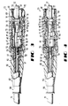
- FIG. 3 is a side elevational view partially in section which shows the connector of FIG. 1 in an assembled state;
- FIG. 4 is an elevational view of the assembled connector rotated 90° to the view of FIG. 3 to show a key of a grip in which portions of the connector are received;
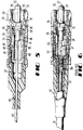
- FIG. 5 is a side elevational view partially in section of a connector of this invention which is used to terminate a buffered optical fiber;
- FIG. 6 is a side elevational view partially in section of a prior art connector;
- FIG. 7 is an exploded perspective view of the optical fiber connector of FIG. 1 and a coupling housing in which the optical fiber connector and another identical optical fiber connector are to be disposed;
- FIG. 8 is an end view in section of the assembled connector of FIG. 3 showing portions of the grip latched into grooves of a plug frame to secure together portions of the connector; and
- FIG. 9 is an end view of the assembled connector of FIG. 8 with forces being applied to diagonally opposed corners thereof to cause disengagement of the latching portions of the grip with the plug frame.
- Referring now to FIG. 1, there is shown a connector which is designated generally by the
numeral 20 which is adapted to terminate anoptical fiber cable 21. Theconnector 20 comprises a ferrule assembly which is designated generally by thenumeral 22. The ferrule assembly includes a barrel 24 (see also FIG. 2) having a segmentedcollar 26 at one end thereof. For the purpose of antirotation thecollar 26 is provided with segments 28-28 with agroove 29 formed between each adjacent two of the segments. Four segments 28-28 are preferred but more or less could be used. Extending from a cavity in an opposite side of thecollar 26 is aferrule 30 which is made of a ceramic material, for example, and which has an opticalfiber receiving passageway 32 formed along a longitudinal centerline axis thereof. Further, a free end of theferrule 30 has abeveled portion 34 which facilitates insertion of the ferrule into an alignment device. In order to facilitate the insertion of one end portion of an optical fiber 35 (see also FIGS. 3 and 4) of thecable 21 to be terminated by the ferrule, the barrel includes abore 36 which is aligned with the passageway in the ferrule and anentrance 37 to the ferrule passageway is funnel-shaped. For a buffered optical fiber, for example, the buffer layer extends to theentrance 37. - Adapted to be assembled with the
ferrule assembly 22 are aspring 38 and cable retention member 40 (see also FIGS. 2-4). Thecable retention member 40 is cylindrically shaped and includes apocket portion 42 adapted to receive thebarrel 24 and thespring 38 of the ferrule assembly. Projecting from an outer surface of thepocket portion 42 are circumferentially disposed tabs 44-44 which are useful for securing the cable retention member to another portion of the connector to be described hereinafter. Also, thecable retention member 40 includes acircumferential groove 45,collars member retention portion 49. The strengthmember retention portion 49 is adapted to have strength members 47-47 included in a sheath system of a single optical fiber cable extend into engagement therewith. - Adapted to be assembled to the
cable retention member 40 is acrimp portion 50 which includes a steppedcylindrical sleeve 52 having asmall diameter portion 54 and alarge diameter portion 56. Thesleeve 52 is adapted to be crimped about an end portion of a single optical fiber cable to be terminated by theconnector 20. Amandrel 58 includes aflange 59 and atubular portion 61. An end portion of thecable 21 to be terminated with themandrel 58 already preinserted is moved into thecrimp portion 50 such that thetubular portion 61 becomes disposed inside the sheath of the cable. Theflange 59 becomes disposed just outside the strengthmember retention portion 49 or to the left thereof as viewed in FIG. 3. After the optical fiber from the end portion of the cable has been extended into the ferrule assembly such that an end of the fiber extends from the ferrule, a craftsperson causes thesleeve portion 54 to be crimped about the cable and thesleeve portion 56 to be crimped about the strength members of the cable from which the jacket has been removed. Thetubular portion 61 of themandrel 58 acts as an anvil during the crimping action to prevent damage to the optical fiber. Strength members 47-47 of the cable such as aramid fiber strength members are disposed about the periphery of the cable retention member and become gripped between theportions 56 and thecable retention member 49 as a result of the crimping (see FIGS. 3 and 4). - Should the optical fiber cable be simply a buffered fiber 63 (see FIG. 5) with no strength members, then the
crimp portion 50 is deemed unnecessary. In that arrangement, the optical fiber cable extends into thebarrel portion 24 and thefiber 35 into thepassageway 32. - The
ferrule assembly 22, thespring 38, thecable retention member 40 and a plug frame which is designated generally by the numeral 70 are adapted to be assembled (see FIGS. 1 and 2) together in what may be referred to as a cable or optical fiber terminator portion of the connector. The cable or optical fiber terminator portion may be factory preassembled. Factory assembly saves time and assembly costs in the field. - The
plug frame 70 may be made of a plastic material such as polycarbonate and includes aforward end portion 72 which is formed with four chamfers 74-74 one at each two intersecting surfaces 73-73. Theforward end portion 72 which includes acavity 75 having a circular cross section is integral with arear end portion 76 which has a circular tubular configuration in a transverse cross-section. Therear end portion 76 includes two diametrically opposed longitudinally extending slots 78-78 and two circumferentially extending windows 79-79. Therear end portion 76 includes a bore 77 (see FIG. 4) for receiving the ferrules and which transitions through a tapered portion to thecavity 75. Each of a plurality of splines 81-81 (see FIG. 3) project radially inwardly from the inner surface of the plug frame. Projecting from eachouter surface 73 adjacent to the junction with the rear end portion is adetent 91. - As should be apparent from FIG. 2, the
forward end portion 72 of theplug frame 70 is symmetrical in a cross section transverse of the longitudinal axis of the plug frame. In the prior art connector, the leading end was unsymmetrical. - When the
ferrule assembly 22 is assembled to theplug frame 70, theferrule 30 is received in the forward end portion and thebarrel 24 is received in thetubular end portion 76. Segmented portions of the ferrule assembly become disposed between the internally projecting splines 81-81. This prevents rotation of theferrule assembly 22 relative to theplug frame 70. Furthermore, when the ferrule assembly and the cable retention member are assembled to the plug frame, the tabs 44-44 radially projecting from the pocket portion of the cable retention member snap-lock into the windows 79-79 of the plug frame to hold the cable retention member secured to the plug frame. - Then the craftsperson tests the cable terminator portion comprising the
ferrule assembly 22, thespring 38, theplug frame 70 and thecable retention portion 40 to determine the direction of any eccentricity of thepassageway 32 in theferrule 30. After this has been determined, the craftsperson provides a marking or otherwise identifies such direction on theplug frame 70. - Then an end portion of a cable which is to be terminated by the
connector 20 is prepared. An outer jacket is removed from an end portion to expose strength members 47-47 or to expose an optical fiber. Provisions are included for holding the end portion of the cable secured to the connector. - The
connector 20 also is provided with a cable strain relief portion 80 (see FIGS. 1-4). The cablestrain relief portion 80 includes aportion 82 which is flexible and includes alarge diameter portion 83 and asmall diameter portion 84 joined by a taperedportion 86. Projecting from thelarge diameter portion 83 is arigid portion 87 which includes a plurality of segments 88-88 each having a hook-like end portion 89. - During the assembly of the
strain relief portion 80 with other portions of the connector, therigid portion 88 is moved over thecrimp portion 50. Movement of thestrain relief portion 80 is discontinued when the hook-like end portions 89-89 snap-lock into thecircumferential groove 45 in thecable retention member 40. - This arrangement also is a departure from the prior art. In the prior art connector of FIG. 6, hook-like end portions of the rigid portion of the cable strain relief portion latch behind an end portion of the
crimp portion 50 instead of in a groove of the cable retention member. Because the cable retention member is secured to the plug frame, the securing of the strain relief portion to the cable retention member provides a more integral structure. Also, advantageously the same elements of theconnector 20 are used to secure the cable retention member to the plug frame in those instances when the transmission media structure being terminated does not include strength members and the crimp portion is not used. - As will be recalled, FIG. 5 depicts a connector of this invention which is adapted to be used to terminate a buffered optical fiber instead of a cable. For such an embodiment, the
strain relief portion 82 of FIGS. 3-4 is modified to have the configuration shown in FIG. 5 and designated with the numeral 85. - Then the craftsperson assembles the terminated cable comprising the
cable 21, thestrain relief portion 80, and thecrimp portion 50 and the cable terminator with a grip which is designated generally by the numeral 90 (see FIG. 1). The grip and the plug frame assembly are configured so that the plug frame with theforward end portion 72 may be in any of four rotational orientations with respect to the grip and be assembled thereto. As will be recalled a forward end portion of the plug frame is symmetrical in a cross section normal to a longitudinal axis of the connector. The assembly is made so that the marking on theplug frame 70 is aligned with a key 92 projecting from anouter surface 94 of its grip. In this way, the key 92 is indicative of the direction of eccentricity of the plug passageway. By causing the direction of eccentricity of the plug passageway of one ferrule assembly to be in the same quadrant of another ferrule assembly to which it is optically connected, losses are reduced substantially. Of course, it should be understood that the direction of eccentricity could be that of the core of the optical fiber in which situation, the determination of eccentricity is made after the cable has been terminated by the cable terminator portion of theconnector 20. - Such an arrangement is advantageous over the prior art. In a prior art SC connector (see FIG. 6), the terminated cable had to be in a predetermined orientation with respect to the
grip 90 to enable assembly. Hence for the direction of eccentricity of the ferrule passageway or of the optical fiber core to be aligned with the key 92, the ferrule assembly had to be assembled to the plug frame such that the eccentricity was in a particular direction with respect to the plug frame. This required that the direction of eccentricity be determined prior to the assembly of the ferrule assembly to the plug frame. With the arrangement of this invention, the ferrule assembly is assembled to the plug frame after which the direction of eccentricity of the plug passageway or fiber core is determined. The direction of eccentricity can be determined before or after the optical fiber is disposed in the ferrule passageway. - It also should be mentioned that the arrangement of the segmented collar of the
ferrule assembly 22 and the splines 81-81 can be used to cause the quadrant of eccentricity of the optical fiber core or passageway in the ferrule to be aligned with a particular spline which causes it to have a known orientation with respect to an outer portion of the plug frame. - As can be seen in the drawings, the
grip 90 comprises an elongatedplastic housing 96 having one end 98 (se FIG. 1) into which the plug frame assembly is inserted and anopposite end 99 which is adapted to be inserted into a coupling housing 100 (see FIG. 7) in order to facilitate an optical connection between two optical fibers terminated by two ferrule assemblies. The assembly is made to cause the key 92 of the grip to be received in akeyway 102 of thehousing 100. A free end portion of aferrule 30 is received in an alignment sleeve 105 (see FIG. 7). At itsend 98, thehousing 96 is formed with two locking nubs 101-101 formed in opposite internal corners. Each lockingnub 101 is adapted to snap-lock into a groove 103 (see FIG. 2) along one of the chamfers 74-74 of the plug frame (see FIG. 8). This secures the plug frame to the grip. In order to disassemble the plug frame from the grip, a craftsperson need only squeeze the grip at opposite corners thereof (see FIG. 9). This causes the tabs to become disposed outside the grooves of the plug frame and allows the plug frame assembly to be withdrawn from the housing of the grip. - As can be seen in FIG. 7, the
coupling housing 100 is formed with two longitudinally aligned keyways 102-102. When two connectors 20-20 each including a grip are inserted into the housing with the keys aligned axially, the connectors become connected such that the quadrant direction of eccentricity of the ferrule passageways or fiber cores are aligned. - The connector also has provisions for becoming secured to the
coupling housing 100. As will be recalled, eachforward surface 73 of theplug frame 70 is formed with adetent 91 projecting therefrom. As is seen in FIG. 7, the near end of the coupling housing includes adepressible latching finger 106. Asecond latching finger 106 extends from an opposite wall but is not seen in FIG. 7. The far end of the coupling housing also is provided with a pair of opposed latching fingers. Aconnector 20 is inserted into the coupling housing until the latching fingers 106-106 associated with that end of the housing into which the connector is inserted ride past beams 107-107 which define openings 108-108 and along sidewalls 109-109 and snap-lock behind opposed detents 91-91 of the plug frame. Because the plug frame is provided with four such detents 91-91, the latching of theconnector 20 to thecoupling housing 100 can occur notwithstanding which of four orientations, 90° to one another, the plug frame is in relative to the coupling housing. - The configurations of the detents 91-91 and of the latching fingers 106-106 are such that upon the application of forces of a predetermined magnitude, typically on the order of about 2-4 lbs. to the
grip 90 in a direction toward thecable 21, the latching fingers 106-106 are cammed up along the sidewalls 109-109 which causes the latching fingers to be spread apart to facilitate withdrawal of theconnector 20 from thecoupling housing 100. - Another feature of the
connector 20 is shown in FIG. 7. Thegrip 90 is formed to include ports 110-110 which allow viewing of theplug frame 70 which may be a different color than that of the grip. During insertion of thegrip 90 into acoupling housing 100, the non-visibility of the ports is indicative of full insertion of the grip into the coupling housing. This feature avoids the need to provide a secondary marking on the grip, the non-visibility of such serving the same function.
Claims (10)
- An optical fiber connector, said connector comprising a ferrule assembly including a ferrule portion having a passageway for an optical fiber, and a barrel, a plug frame in which is disposed said ferrule assembly, said barrel of said ferrule assembly projecting toward a latching end portion of said plug frame and said ferrule projecting toward an opposite end portion of said plug frame, said opposite end portion of said plug frame being symmetrical with respect to a cross section of said plug frame which is normal to a longitudinal axis of said connector and spring means disposed about said portion of said ferrule assembly which projects toward said latching end portion of said plug frame, characterized by
a cable retention member which is assembled to said plug frame and which includes a pocket for said spring means and said barrel, said cable retention member including outwardly projecting tabs each of which is received in a slot in said latching end portion of said plug frame to secure said cable retention member to said plug frame, said cable retention means being effective to preload said spring means, and
a housing in which said plug frame is disposed and which has a longitudinal axis, said plug frame capable of being assembled to said housing in any one of a plurality of rotational orientations with respect to the longitudinal axis of said connector. - The optical fiber connector of claim 1, which also includes a crimp portion which includes a sleeve which includes a large diameter portion which is capable of being crimped about a portion of said cable retention member with portions of a cable sheath system disposed between said large diameter portion of said crimp portion and said cable retention member and a small diameter portion which is capable of being crimped about a portion of a cable.
- The optical fiber connector of claim 2, wherein a central portion of said cable retention member includes circumferentially extending tabs each of which is adapted to be received in an opening of said plug frame to secure said cable retention member to said plug frame.
- The optical fiber connector of claim 3, wherein said connector comprises a grip which includes said housing and which includes a leading end portion having outer surfaces and a central cavity for receiving said plug frame assembly and a key projecting from one of the outer surfaces of the leading end portion of said housing, said opposite end portion of said plug frame including four outer orthogonal surfaces and being capable of being assembled to said grip such that any one of said outer surfaces of said opposite end portion of said plug frame is aligned with said key.
- The optical fiber connector of claim 4, wherein said plug frame is assembled to said grip to cause the direction of any eccentricity of said passageway in said ferrule to be in the same quadrant as said key.
- A terminated optical fiber, which includes a length of optical fiber, an optical fiber connector which terminates said length of optical fiber, said optical fiber connector comprising a ferrule assembly including a ferrule portion having a passageway for an optical fiber, and a barrel, a plug frame in which is disposed said ferrule assembly, said barrel of said ferrule assembly projecting toward a latching end portion of said plug frame and said ferrule projecting toward an opposite end portion of said plug frame, said opposite end portion of said plug frame being symmetrical with respect to a cross section of said plug frame which is normal to a longitudinal axis of said connector, and spring means disposed about said portion of said ferrule assembly which projects toward said latching end portion of said plug frame; characterized by
a cable retention member which is assembled to said plug frame and which includes a pocket for said spring means and said barrel portion, said cable retention member including outwardly projecting tabs each of which is received in a slot in said latching end portion of said plug frame to secure said cable retention member to said plug frame, said cable retention means being effective to preload said spring means; and
a housing in which said plug frame is disposed and which has a longitudinal axis, said plug frame capable of being assembled to said housing in any one of a plurality of rotational orientations with respect to the longitudinal axis of said connector. - The terminated optical fiber of claim 6, wherein a central portion of said cable retention member includes circumferentially extending tabs each of which is adapted to be received in an opening of said plug frame to secure said cable retention member to said plug frame.
- The terminated optical fiber of claim 7, which also includes a grip which includes said housing in which said plug frame is disposed, said housing of said grip including a leading end portion which includes outer surfaces and which includes a central cavity for receiving said plug frame and a key projecting from one of said outer surfaces of said housing of said grip, said opposite end portion of said plug frame including four outer orthogonal surfaces and being capable of being assembled to said grip such that any one of said outer surfaces of said opposite end portion of said plug frame is aligned with said key.
- The terminated optical fiber of claim 8, wherein said plug frame is assembled to said grip to cause the direction of eccentricity of said passageway in said ferrule to be in the same quadrant as said key.
- The terminated optical fiber of claim 9, wherein two opposed inner portions of said grip of said leading end portion of said grip are provided with inwardly projecting latching nubs, said opposite end portion of said plug frame including a beveled surface at the intersection of each two surfaces of said opposite end portion of said plug frame, said beveled surface being an invert of a groove formed by sidewalls which connect to orthogonal surfaces of said opposite end portion of said plug frame, whereupon assembly of said plug frame to said housing of said grip, one of said latching nubs of said housing of said grip becomes disposed in one of said grooves and the opposed one of said latching nubs becomes disposed in a diagonally opposite one of said grooves.
Applications Claiming Priority (2)
| Application Number | Priority Date | Filing Date | Title |
|---|---|---|---|
| US07/889,203 US5212752A (en) | 1992-05-27 | 1992-05-27 | Optical fiber ferrule connector having enhanced provisions for tuning |
| US889203 | 1992-05-27 |
Publications (3)
| Publication Number | Publication Date |
|---|---|
| EP0572174A2 true EP0572174A2 (en) | 1993-12-01 |
| EP0572174A3 EP0572174A3 (en) | 1994-08-24 |
| EP0572174B1 EP0572174B1 (en) | 1999-04-14 |
Family
ID=25394688
Family Applications (1)
| Application Number | Title | Priority Date | Filing Date |
|---|---|---|---|
| EP93303912A Expired - Lifetime EP0572174B1 (en) | 1992-05-27 | 1993-05-20 | Optical fiber ferrule connector having enhanced provisions for tuning |
Country Status (11)
| Country | Link |
|---|---|
| US (3) | US5212752A (en) |
| EP (1) | EP0572174B1 (en) |
| JP (2) | JP2837608B2 (en) |
| KR (1) | KR100296529B1 (en) |
| AU (1) | AU643915B1 (en) |
| CA (1) | CA2096058C (en) |
| DE (1) | DE69324404T2 (en) |
| DK (1) | DK0572174T3 (en) |
| NO (1) | NO309787B1 (en) |
| NZ (1) | NZ247693A (en) |
| TW (1) | TW222688B (en) |
Cited By (8)
| Publication number | Priority date | Publication date | Assignee | Title |
|---|---|---|---|---|
| EP0668521A1 (en) * | 1994-02-22 | 1995-08-23 | The Whitaker Corporation | Captivated fiber optic connector |
| EP1041416A2 (en) * | 1999-04-01 | 2000-10-04 | Lucent Technologies Inc. | Tunable optical fiber buildout |
| EP1091226A1 (en) * | 1999-10-06 | 2001-04-11 | Lucent Technologies Inc. | An optical connector having a one-piece housing |
| EP1143275A2 (en) * | 2000-04-07 | 2001-10-10 | Panduit Corporation | Fiber optic sleeve with tapered corner-wall sections |
| WO2002052310A2 (en) * | 2000-12-27 | 2002-07-04 | Adc Telecommunications, Inc. | Tunable fiber optic connector and method for assembling |
| EP1450188A2 (en) * | 2003-02-21 | 2004-08-25 | Itt Manufacturing Enterprises, Inc. | Optic fiber terminus indexer |
| GB2448935A (en) * | 2007-05-04 | 2008-11-05 | Miniflex Ltd | Optical fibre connector |
| CN102122030A (en) * | 2010-01-08 | 2011-07-13 | Ofs飞泰尔有限责任公司 | Connector cover for outside plant applications |
Families Citing this family (236)
| Publication number | Priority date | Publication date | Assignee | Title |
|---|---|---|---|---|
| US5528711A (en) * | 1989-11-24 | 1996-06-18 | Nippon Telegraph And Telephone Corp. | Optical connector for connecting a plurality of optical plugs to a connector housing |
| US5212752A (en) * | 1992-05-27 | 1993-05-18 | At&T Bell Laboratories | Optical fiber ferrule connector having enhanced provisions for tuning |
| US5289554A (en) * | 1992-09-29 | 1994-02-22 | Minnesota Mining And Manufacturing Company | Keying element for fiber connector |
| AU660859B2 (en) * | 1992-11-26 | 1995-07-06 | Diamond S.A. | Sleeve portion for an optical fibre plug connector |
| EP0860721B1 (en) * | 1993-03-31 | 2002-06-26 | Sumitomo Electric Industries, Ltd. | Optical fiber array and method of manufacturing |
| US5436995A (en) * | 1993-05-14 | 1995-07-25 | Nippon Telegraph And Telephone Corporation | Optical fiber connector unit and optical fiber connector |
| US5390272A (en) * | 1993-08-31 | 1995-02-14 | Amphenol Corporation | Fiber optic cable connector with strain relief boot |
| US5428703A (en) * | 1994-02-18 | 1995-06-27 | Augat Inc. | One-piece SC fiber optic connector |
| US5631986A (en) * | 1994-04-29 | 1997-05-20 | Minnesota Mining And Manufacturing Co. | Optical fiber ferrule |
| JP3483889B2 (en) * | 1994-06-22 | 2004-01-06 | ザ ウィタカー コーポレーション | Optical fiber connector having assemblability improving means |
| US5481634A (en) * | 1994-06-24 | 1996-01-02 | At&T Corp. | Connector for optical fiber |
| US5461690A (en) * | 1994-07-29 | 1995-10-24 | At&T Ipm Corp. | Bend-limiting apparatus for a cable |
| US5717802A (en) * | 1994-09-19 | 1998-02-10 | The Whitaker Corporation | Fiber optic connectors having spring-loaded ferrules |
| CA2162515C (en) * | 1994-12-22 | 2000-03-21 | Leonard George Cohen | Jumper tracing system |
| US6220878B1 (en) | 1995-10-04 | 2001-04-24 | Methode Electronics, Inc. | Optoelectronic module with grounding means |
| US5546281A (en) | 1995-01-13 | 1996-08-13 | Methode Electronics, Inc. | Removable optoelectronic transceiver module with potting box |
| US5717533A (en) | 1995-01-13 | 1998-02-10 | Methode Electronics Inc. | Removable optoelectronic module |
| US5559922A (en) * | 1995-02-28 | 1996-09-24 | Lucent Technologies Inc. | Wire guide and optical fiber storage spool assembly |
| US5530787A (en) * | 1995-02-28 | 1996-06-25 | At&T Corp | Optical fiber guide for preventing sharp bends |
| US5748819A (en) * | 1995-04-05 | 1998-05-05 | Siecor Corporation | Field installable optical fiber connector and an associated method of fabrication |
| US5682451A (en) * | 1995-05-23 | 1997-10-28 | Minnesota Mining And Manufacturing Company | Device with internal features for rotational alignment of non-cylindrically symmetrical optical elements |
| US5633970A (en) * | 1995-05-23 | 1997-05-27 | Minnesota Mining And Manufacturing Company | Device with internal asymmetrical features for rotational alignment of non-symmetrical articles |
| US5664955A (en) * | 1995-09-26 | 1997-09-09 | Lucent Technologies Inc. | Protective hood |
| US5638481A (en) * | 1995-09-26 | 1997-06-10 | Lucent Technologies Inc. | Flush mounted outlet |
| US5659650A (en) * | 1995-09-26 | 1997-08-19 | Lucent Technologies Inc. | Hinged faceplate |
| US5671310A (en) * | 1995-11-16 | 1997-09-23 | Tai Jin Mold Mfg. Co., Ltd. | Optical fiber connector having an adjustable engaging extent |
| US5687268A (en) * | 1995-11-27 | 1997-11-11 | Lucent Technologies Inc. | Pivotable optical shutter for blocking emission from a lightguide adapter #5 |
| US5661843A (en) * | 1996-01-30 | 1997-08-26 | Rifocs Corporation | Fiber optic probe |
| US5712938A (en) * | 1996-05-30 | 1998-01-27 | Tai Jin Mold Mfg. Co. | Optical fiber connector |
| JP3145639B2 (en) * | 1996-07-10 | 2001-03-12 | 三菱電線工業株式会社 | Optical connector for high energy |
| US5768455A (en) * | 1996-11-19 | 1998-06-16 | Lucent Technologies Inc. | Fiber optic connector |
| US5896477A (en) * | 1997-05-16 | 1999-04-20 | Lucent Technologies Inc. | Optical fiber coupling buildout system |
| US5883995A (en) * | 1997-05-20 | 1999-03-16 | Adc Telecommunications, Inc. | Fiber connector and adapter |
| JPH1138276A (en) * | 1997-07-22 | 1999-02-12 | Seiko Giken:Kk | Structure of optical connector and its alignment method |
| US5915056A (en) * | 1997-08-06 | 1999-06-22 | Lucent Technologies Inc. | Optical fiber strain relief device |
| US5987203A (en) * | 1997-10-09 | 1999-11-16 | Lucent Technologies Inc. | Distribution module for optical couplings |
| US5923805A (en) * | 1997-12-22 | 1999-07-13 | Lucent Technologies Inc. | Connector for plastic optical fiber |
| JPH11218652A (en) * | 1998-02-03 | 1999-08-10 | Seiko Giken Kk | Light source assembly of optical fiber and its manufacture |
| EP0938003A1 (en) * | 1998-02-24 | 1999-08-25 | Jds Fitel Inc. | Tunable multiple fiber optical connector |
| US5930425A (en) * | 1998-04-21 | 1999-07-27 | Lucent Technologies Inc. | High density coupling module |
| US6203333B1 (en) | 1998-04-22 | 2001-03-20 | Stratos Lightwave, Inc. | High speed interface converter module |
| US6179627B1 (en) | 1998-04-22 | 2001-01-30 | Stratos Lightwave, Inc. | High speed interface converter module |
| US6010250A (en) | 1998-07-09 | 2000-01-04 | Sung; Allen L. | Plug for fibre optic cable |
| US6188827B1 (en) | 1998-09-04 | 2001-02-13 | Lucent Technologies Inc. | Attenuator element for a buildout system |
| US6196729B1 (en) | 1998-09-04 | 2001-03-06 | Lucent Technologies Inc. | Apparatus for retaining an attenuator element |
| US6220763B1 (en) | 1998-09-04 | 2001-04-24 | Lucent Technologies Inc. | Optical fiber buildout system |
| US6149315A (en) * | 1998-09-04 | 2000-11-21 | Lucent Technologies Inc. | Side load resistant buildout |
| US6357933B1 (en) | 1999-03-30 | 2002-03-19 | Lucent Technologies Inc. | Quick connect optical fiber ferrule connector |
| US6447172B1 (en) * | 1999-04-01 | 2002-09-10 | Fitel Usa Corp. | Sleeve holder for optical fiber buildout |
| US6524014B2 (en) | 1999-04-01 | 2003-02-25 | Fitel Usa Corp. | Universal modular optical fiber buildout |
| US6188825B1 (en) | 1999-04-15 | 2001-02-13 | Lucent Technologies, Inc. | Dust cover for protecting optical fiber sleeve housing |
| US6464402B1 (en) * | 1999-07-28 | 2002-10-15 | Fitel Usa Corp. | Optical fiber connector tuning index tool |
| US6287018B1 (en) | 1999-07-28 | 2001-09-11 | Lucent Technologies Inc. | Tunable optical fiber connector |
| US6220873B1 (en) | 1999-08-10 | 2001-04-24 | Stratos Lightwave, Inc. | Modified contact traces for interface converter |
| US6325547B1 (en) * | 1999-10-06 | 2001-12-04 | Lucent Technologies Inc. | Optical connector having a housing assembly that is comprised of polyphenylsulfone |
| US6367984B1 (en) | 1999-11-10 | 2002-04-09 | Lucent Technologies, Inc. | Optical fiber adapter |
| US6398423B1 (en) | 1999-12-15 | 2002-06-04 | Itt Manufacturing Enterprises, Inc. | Optic fiber retaining system |
| US6318903B1 (en) * | 2000-02-29 | 2001-11-20 | Lucent Technologies Inc. | Optical fiber connector for backplane |
| US9239441B2 (en) | 2000-05-26 | 2016-01-19 | Corning Cable Systems Llc | Fiber optic drop cables and preconnectorized assemblies having toning portions |
| US6648520B2 (en) * | 2001-09-28 | 2003-11-18 | Corning Cable Systems Llc | Fiber optic plug |
| US6450697B1 (en) * | 2000-08-24 | 2002-09-17 | Berg Technology, Inc. | Optical connector having a combined guide pin lock and grounding contact |
| US6572276B1 (en) * | 2000-11-21 | 2003-06-03 | Euromicron Werkezeuge Gmbh | Plug for fiber optic cables with a plug housing |
| US6540410B2 (en) * | 2000-12-18 | 2003-04-01 | Corning Cable Systems Llc | Panel-mounted fiber optic connector |
| US6517255B2 (en) * | 2000-12-20 | 2003-02-11 | Paul M. Mulligan | Plastic optical fiber connector |
| US6554484B2 (en) | 2000-12-27 | 2003-04-29 | Fitel Usa Corp. | Optical connector receptacle having switching capability |
| US6461057B2 (en) * | 2001-01-12 | 2002-10-08 | Mao-Hsiang Chen | Simply structural and easily assembled optical fiber connector |
| US6852386B2 (en) * | 2001-03-08 | 2005-02-08 | Norbord Inc. | Composite board with OSB faces |
| US6663293B2 (en) | 2001-03-16 | 2003-12-16 | Fitel Usa Corp. | Tunable optical fiber connector |
| US6609837B2 (en) | 2001-04-27 | 2003-08-26 | Fitel Usa Corp. | Optical fiber adapter for dissimilar size ferrules |
| US6652155B2 (en) | 2001-06-21 | 2003-11-25 | Fitel Usa Corp. | Optical connector plug |
| JP2003185881A (en) * | 2001-10-12 | 2003-07-03 | Seiko Instruments Inc | Ferrule |
| US6550979B1 (en) * | 2001-10-19 | 2003-04-22 | Corning Cable Systems Llc | Floating connector subassembly and connector including same |
| US6916120B2 (en) * | 2002-01-30 | 2005-07-12 | Adc Telecommunications, Inc. | Fiber optic connector and method |
| US6629782B2 (en) | 2002-02-04 | 2003-10-07 | Adc Telecommunications, Inc. | Tuned fiber optic connector and method |
| CN1442712A (en) * | 2002-03-01 | 2003-09-17 | 爱普迪科技有限公司 | Regulatable ST type connecting head and its regulating method |
| US6688781B2 (en) | 2002-03-11 | 2004-02-10 | Fitel Usa Corp. | Optical connector adapter having switching capability |
| US6655851B1 (en) * | 2002-05-22 | 2003-12-02 | Fiberon Technolgies, Inc. | Optical fiber connector |
| US6913396B2 (en) * | 2002-11-01 | 2005-07-05 | Adc Telecommunications, Inc. | Tunable fiber optic connector and device and method for tuning a connector |
| US6918704B2 (en) * | 2003-01-30 | 2005-07-19 | Panduit Corp. | Tunable fiber optic connector |
| CA2454438A1 (en) * | 2003-02-07 | 2004-08-07 | Hypertronics Corporation | Connecting device |
| US6923578B2 (en) * | 2003-02-21 | 2005-08-02 | Itt Manufacturing Enterprises, Inc. | Optical terminus keying |
| US7393142B2 (en) * | 2003-08-29 | 2008-07-01 | Corning Cable Systems Llc | Molded ferrule with reference surface for end face geometry measurement |
| US6962445B2 (en) | 2003-09-08 | 2005-11-08 | Adc Telecommunications, Inc. | Ruggedized fiber optic connection |
| US7674046B2 (en) * | 2003-09-22 | 2010-03-09 | Belden Cdt (Canada) Inc. | Fibre optic connector keying system |
| JP3925928B2 (en) * | 2003-10-01 | 2007-06-06 | 日本航空電子工業株式会社 | Optical connector disassembly jig |
| US7201518B2 (en) * | 2004-04-14 | 2007-04-10 | Adc Telecommunications, Inc. | Fiber optic connector and method |
| DE202004009156U1 (en) * | 2004-06-09 | 2005-10-27 | Keitz, Andreas Von | Emergency disconnect system for optical fibers has sleeve on end of first fiber with expanded extension engaging outside of cylindrical sleeve on end of second fiber |
| KR100507543B1 (en) * | 2004-06-30 | 2005-08-09 | 주식회사 골드텔 | Optical connector |
| GB2423155B (en) * | 2005-02-10 | 2009-09-09 | Agilent Technologies Inc | Keyed transceiver module |
| EP1736095A1 (en) * | 2005-06-22 | 2006-12-27 | Royal College Of Art | Speculum |
| US8422835B2 (en) * | 2005-06-30 | 2013-04-16 | Weatherford/Lamb, Inc. | Optical waveguide feedthrough assembly |
| DE202006011910U1 (en) * | 2005-11-09 | 2007-03-22 | Weidmüller Interface GmbH & Co. KG | Adapter for receiving a plug part |
| KR101135187B1 (en) * | 2005-11-28 | 2012-04-16 | 주식회사 케이티 | Optical connector |
| US7682088B2 (en) * | 2006-06-19 | 2010-03-23 | Commscope, Inc. Of North Carolina | Non-halogen fiber optic connectors |
| US7614797B2 (en) * | 2007-01-24 | 2009-11-10 | Adc Telecommunications, Inc. | Fiber optic connector mechanical interface converter |
| US7591595B2 (en) * | 2007-01-24 | 2009-09-22 | Adc Telelcommunications, Inc. | Hardened fiber optic adapter |
| US7572065B2 (en) | 2007-01-24 | 2009-08-11 | Adc Telecommunications, Inc. | Hardened fiber optic connector |
| ITBO20070279A1 (en) * | 2007-04-17 | 2008-10-18 | Tec Mo S R L | CONNECTOR DEVICE |
| US7677814B2 (en) * | 2007-05-06 | 2010-03-16 | Adc Telecommunications, Inc. | Mechanical interface converter for making non-ruggedized fiber optic connectors compatible with a ruggedized fiber optic adapter |
| WO2008137893A1 (en) * | 2007-05-06 | 2008-11-13 | Adc Telecommunications, Inc. | Interface converter for sc fiber optic connectors |
| US7686519B2 (en) * | 2007-06-18 | 2010-03-30 | Adc Telecommunications, Inc. | Hardened fiber optic housing and cable assembly |
| US7762726B2 (en) | 2007-12-11 | 2010-07-27 | Adc Telecommunications, Inc. | Hardened fiber optic connection system |
| CN102066999B (en) * | 2008-04-21 | 2013-05-29 | Adc电信公司 | Hardened fiber optic connector with connector body joined to cylindrical cable by unitary housing |
| WO2010068890A1 (en) * | 2008-12-11 | 2010-06-17 | Afl Telecommunications Llc | A "secured" fiber optic connecting system and method using offset fiber position in a single-fiber connector |
| TW200944854A (en) * | 2009-06-18 | 2009-11-01 | Protai Photonic Co Ltd | Optical fiber connector and adapter |
| US8408815B2 (en) * | 2009-06-18 | 2013-04-02 | Senko Advanced Components, Inc. | Optical fiber connector and adapter |
| ES2905430T3 (en) * | 2009-09-28 | 2022-04-08 | Te Connectivity Nederland Bv | Sealing housing for a connector on a cable, such as a standard fiber optic connector |
| WO2012075121A2 (en) | 2010-11-30 | 2012-06-07 | Adc Telecommunications, Inc. | Lc connector and method of assembly |
| US9188747B2 (en) | 2011-05-23 | 2015-11-17 | Senko Advanced Components, Inc. | True one piece housing fiber optic adapter |
| KR101680173B1 (en) | 2011-10-05 | 2016-11-28 | 센코 어드밴스드 컴포넌츠, 인코포레이티드 | Latching connector with remote release |
| IN2014KN01743A (en) * | 2012-02-20 | 2015-10-23 | Adc Telecommunications Inc | |
| US8974124B2 (en) | 2012-08-16 | 2015-03-10 | Senko Advanced Components, Inc. | Fiber optic connector |
| CN102854579B (en) * | 2012-09-06 | 2016-04-20 | 深圳日海通讯技术股份有限公司 | There is the intelligent acess plug of integrated casing |
| US9081154B2 (en) | 2012-09-12 | 2015-07-14 | Tyco Electronics Raychem Bvba | Method of tuning a fiber optic connector |
| US9146362B2 (en) | 2012-09-21 | 2015-09-29 | Adc Telecommunications, Inc. | Insertion and removal tool for a fiber optic ferrule alignment sleeve |
| EP2926181B1 (en) | 2012-11-30 | 2020-04-15 | CommScope Technologies LLC | Fiber optic connector with field installable outer connector housing |
| WO2014085459A1 (en) | 2012-11-30 | 2014-06-05 | Tyco Electronics Corporation | Distributed split configuration for multi-dwelling unit |
| WO2014168990A1 (en) * | 2013-04-08 | 2014-10-16 | Advanced Fiber Products, LLC | Secure sc optical fiber connector and removal tools |
| US9268103B2 (en) | 2013-05-10 | 2016-02-23 | Senko Advanced Components, Inc. | Interlockable fiber optic connector adaptors |
| CN103246023B (en) * | 2013-05-15 | 2016-05-04 | 深圳市特发信息光网科技股份有限公司 | Fiber active linker joint |
| US9360649B2 (en) | 2013-05-22 | 2016-06-07 | Senko Advanced Components, Inc. | Cable guide for fiber optic cables |
| EP3014322B1 (en) | 2013-06-27 | 2018-09-19 | CommScope Connectivity Belgium BVBA | Fiber optic cable anchoring device for use with fiber optic connectors and methods of using the same |
| WO2015028433A1 (en) | 2013-08-24 | 2015-03-05 | Tyco Electronics Raychem Bvba | Ruggedized fiber optic connectors and connection systems |
| US9618703B2 (en) | 2013-10-03 | 2017-04-11 | Senko Advanced Components, Inc. | Connector housing for securing an optical cable and methods of use and manufacture thereof |
| US9285550B2 (en) | 2013-10-21 | 2016-03-15 | Commscope Technologies Llc | Fiber optic connector with rotational interlock between connector housing and rear insert |
| US9477049B2 (en) | 2013-12-20 | 2016-10-25 | Senko Advanced Components, Inc. | Lockable connectors and connection assemblies |
| US9535230B2 (en) | 2014-01-31 | 2017-01-03 | Senko Advanced Components, Inc. | Integrated fiber optic cable fan-out connector |
| CN104849815B (en) | 2014-02-14 | 2017-01-18 | 泰科电子(上海)有限公司 | Optical fiber connector and assembly method therefor |
| CN104849816B (en) * | 2014-02-14 | 2017-01-11 | 泰科电子(上海)有限公司 | Optical fiber connector and assembly method therefor |
| USD787448S1 (en) | 2014-08-18 | 2017-05-23 | Interlemo Holding S.A. | Electrical connector |
| US9297964B2 (en) | 2014-04-18 | 2016-03-29 | Senko Advanced Components, Inc. | Optical fiber connector assembly |
| US9274287B2 (en) | 2014-05-13 | 2016-03-01 | Senko Advanced Components, Inc. | Optical fiber connector and ferrule |
| US9618702B2 (en) | 2014-06-09 | 2017-04-11 | Senko Advanced Components, Inc. | Reduced-profile data transmission element connectors, adapters, and connection assemblies thereof |
| CN105445862B (en) | 2014-07-09 | 2018-01-19 | 泰科电子(上海)有限公司 | The joints of optical fibre and its on-site assembly method |
| BR112017002215B1 (en) * | 2014-08-06 | 2022-05-03 | Prysmian S.P.A. | Fiber optic connector set and pre-connectorized fiber optic cable |
| US9599778B2 (en) | 2014-10-22 | 2017-03-21 | Senko Advanced Components, Inc. | Latching connector with remote release |
| EP3234672B1 (en) | 2014-12-19 | 2021-09-08 | CommScope Telecommunications (Shanghai) Co. Ltd. | Hardened fiber optic connector with pre-compressed spring |
| US9494745B2 (en) | 2015-01-16 | 2016-11-15 | Senko Advanced Components, Inc. | Sealable communication cable connection assemblies |
| US9658409B2 (en) | 2015-03-03 | 2017-05-23 | Senko Advanced Components, Inc. | Optical fiber connector with changeable polarity |
| EP3278155A1 (en) | 2015-04-03 | 2018-02-07 | CommScope Connectivity Belgium BVBA | Low cost hardened fiber optic connection system |
| US9482825B1 (en) * | 2015-04-28 | 2016-11-01 | Senko Advanced Components, Inc | Ingress protected optical fiber connector having small diameter (mini-IP connector) |
| US9448369B1 (en) * | 2015-04-28 | 2016-09-20 | Senko Advanced Components, Inc. | Ingress protected optical fiber connector having small diameter (mini-IP connector) |
| MX2017014377A (en) | 2015-05-15 | 2018-08-15 | Adc Telecommunications Shanghai Distrib Co Ltd | Alignment sleeve assembly and optical fibre adapter. |
| US9684139B2 (en) | 2015-05-29 | 2017-06-20 | Senko Advanced Components, Inc. | Optical fiber connector with changeable gender |
| USD863221S1 (en) | 2015-09-04 | 2019-10-15 | Interlemo Holding Sa | Illuminable female connector |
| US10620385B2 (en) | 2015-11-30 | 2020-04-14 | Commscope Technologies Llc | Fiber optic connector and assembly thereof |
| US10641970B2 (en) | 2015-12-16 | 2020-05-05 | Commscope Technologies Llc | Field installed fiber optic connector |
| CN107193091B (en) | 2016-03-14 | 2020-09-04 | 康普科技有限责任公司 | Enhanced female fiber optic connector cable assembly |
| CN209028258U (en) * | 2016-03-17 | 2019-06-25 | 康宁光电通信有限责任公司 | Tunable optical fiber connector, connector sub-component, CA cable assembly and sub-component |
| US10336644B2 (en) | 2016-05-26 | 2019-07-02 | Corning Optical Communication Llc | Methods of ferrule reshaping for correcting core-to-ferrule concentricity errors, and optical fiber cable assemblies related to such methods |
| US11420293B2 (en) | 2016-05-26 | 2022-08-23 | Corning Optical Communications LLC | Methods of ferrule reshaping for correcting core-to-ferrule concentricity errors, and optical fiber cable assemblies related to such methods |
| US9726830B1 (en) | 2016-06-28 | 2017-08-08 | Senko Advanced Components, Inc. | Connector and adapter system for two-fiber mechanical transfer type ferrule |
| US10067299B2 (en) | 2016-06-29 | 2018-09-04 | Corning Optical Communications LLC | Tunable optical fiber connectors and connector and cable sub-assemblies and assemblies |
| US10228521B2 (en) | 2016-12-05 | 2019-03-12 | Senko Advanced Components, Inc. | Narrow width adapters and connectors with modular latching arm |
| US10078188B1 (en) | 2016-12-05 | 2018-09-18 | Senko Advanced Components, Inc. | Springless push/pull fiber optic connector |
| US10444444B2 (en) | 2017-01-30 | 2019-10-15 | Senko Advanced Components, Inc. | Remote release tab connector assembly |
| US10185100B2 (en) | 2017-01-30 | 2019-01-22 | Senko Advanced Components, Inc | Modular connector and adapter assembly using a removable anchor device |
| US10416394B2 (en) | 2017-01-30 | 2019-09-17 | Senko Advanced Components, Inc. | Fiber optic receptacle with integrated device therein |
| CN110249248B (en) | 2017-01-30 | 2021-07-27 | 扇港元器件股份有限公司 | Optical connector with reversible polarity |
| US11333836B2 (en) | 2017-01-30 | 2022-05-17 | Senko Advanced Components, Inc. | Adapter for optical connectors |
| US10725248B2 (en) | 2017-01-30 | 2020-07-28 | Senko Advanced Components, Inc. | Fiber optic receptacle with integrated device therein incorporating a behind-the-wall fiber optic receptacle |
| US9989712B1 (en) | 2017-03-20 | 2018-06-05 | Senko Advanced Components, Inc | MPO connector assembly with push-pull tab |
| US10359583B2 (en) | 2017-04-07 | 2019-07-23 | Senko Advanced Components, Inc. | Behind the wall optical connector with reduced components |
| US10209461B2 (en) | 2017-04-07 | 2019-02-19 | Senko Advanced Components | Behind the wall optical connector with reduced components |
| US10989884B2 (en) | 2017-04-07 | 2021-04-27 | Senko Advanced Components, Inc. | Behind the wall optical connector with reduced components |
| US10754098B2 (en) | 2017-04-07 | 2020-08-25 | Senko Advanced Components, Inc. | Behind the wall optical connector with reduced components |
| US10718910B2 (en) | 2017-05-03 | 2020-07-21 | Senko Advanced Components, Inc | Field terminated ruggedized fiber optic connector system |
| US10401576B2 (en) | 2017-05-10 | 2019-09-03 | Senko Advanced Components, Inc. | MPO micro-latch-lock connector |
| US10146016B1 (en) | 2017-05-10 | 2018-12-04 | Senko Advanced Components, Inc | MPO micro-latchlock connector |
| US11585987B2 (en) | 2017-05-11 | 2023-02-21 | Ppc Broadband, Inc. | Pushable optical connector with connector-integrated articulation |
| CA3063107A1 (en) | 2017-05-11 | 2018-11-15 | Ppc Broadband, Inc. | Pushable optical connector with connector-integrated articulation |
| US10520686B2 (en) | 2017-05-18 | 2019-12-31 | Senko Advanced Components, Inc. | Optical connector with one-piece body |
| US10359576B2 (en) * | 2017-06-15 | 2019-07-23 | Senko Advanced Components, Inc. | SC low profile connector with optional boot |
| US10359577B2 (en) | 2017-06-28 | 2019-07-23 | Corning Research & Development Corporation | Multiports and optical connectors with rotationally discrete locking and keying features |
| US11187859B2 (en) | 2017-06-28 | 2021-11-30 | Corning Research & Development Corporation | Fiber optic connectors and methods of making the same |
| PL3646095T3 (en) * | 2017-06-28 | 2022-12-05 | Corning Research & Development Corporation | Multiports having keyed connection ports and securing features |
| US11668890B2 (en) | 2017-06-28 | 2023-06-06 | Corning Research & Development Corporation | Multiports and other devices having optical connection ports with securing features and methods of making the same |
| US11300746B2 (en) | 2017-06-28 | 2022-04-12 | Corning Research & Development Corporation | Fiber optic port module inserts, assemblies and methods of making the same |
| US11822133B2 (en) | 2017-07-14 | 2023-11-21 | Senko Advanced Components, Inc. | Ultra-small form factor optical connector and adapter |
| US10281669B2 (en) | 2017-07-14 | 2019-05-07 | Senko Advance Components, Inc. | Ultra-small form factor optical connectors |
| US10641972B2 (en) | 2017-08-17 | 2020-05-05 | Senko Advanced Components, Inc | Anti-jam alignment sleeve holder or connector housing for a ferrule assembly |
| US20190086615A1 (en) * | 2017-09-20 | 2019-03-21 | Corning Optical Communications LLC | Tunable fiber optic connectors, fiber optic cable assemblies including the same, and tuning methods |
| US10444442B2 (en) | 2017-11-03 | 2019-10-15 | Senko Advanced Components, Inc. | MPO optical fiber connector |
| US11160621B2 (en) | 2017-11-17 | 2021-11-02 | Intuitive Surgical Operations, Inc. | Surgical instrument sterile adapter with optical coupler |
| US11002923B2 (en) | 2017-11-21 | 2021-05-11 | Senko Advanced Components, Inc. | Fiber optic connector with cable boot release having a two-piece clip assembly |
| US10578811B2 (en) | 2017-11-29 | 2020-03-03 | Corning Optical Communications LLC | Methods of forming ferrules for optical fiber connectors, and optical fiber cable assemblies related to such methods |
| USD868694S1 (en) * | 2017-11-30 | 2019-12-03 | Corning Research & Development Corporation | Connector for making optical connections |
| USD1002540S1 (en) | 2017-11-30 | 2023-10-24 | Corning Research & Development Corporation | Connector for making optical connections |
| US10678000B2 (en) | 2018-01-05 | 2020-06-09 | Senko Advanced Components, Inc. | Pull rod and alignment key for a fiber optic connector and adapter |
| US11150412B2 (en) * | 2018-01-31 | 2021-10-19 | Commscope Technologies Llc | Tunable fiber optic connectors |
| US11112566B2 (en) | 2018-03-19 | 2021-09-07 | Senko Advanced Components, Inc. | Removal tool for removing a plural of micro optical connectors from an adapter interface |
| CN111033339B (en) | 2018-03-28 | 2023-09-19 | 扇港元器件股份有限公司 | Optical fiber connector |
| US10770831B2 (en) * | 2018-03-30 | 2020-09-08 | Western Technology, Inc. | Strain relief hose barb cable connector |
| US11041993B2 (en) | 2018-04-19 | 2021-06-22 | Senko Advanced Components, Inc. | Fiber optic adapter with removable insert for polarity change and removal tool for the same |
| US10921528B2 (en) | 2018-06-07 | 2021-02-16 | Senko Advanced Components, Inc. | Dual spring multi-fiber optic connector |
| CN112088327A (en) | 2018-07-15 | 2020-12-15 | 扇港元器件股份有限公司 | Ultra-small optical connector and adapter |
| US10444441B1 (en) | 2018-08-10 | 2019-10-15 | Senko Advanced Components, Inc. | Pivotable housing for a fiber optic connector |
| US11073664B2 (en) | 2018-08-13 | 2021-07-27 | Senko Advanced Components, Inc. | Cable boot assembly for releasing fiber optic connector from a receptacle |
| US10921530B2 (en) | 2018-09-12 | 2021-02-16 | Senko Advanced Components, Inc. | LC type connector with push/pull assembly for releasing connector from a receptacle using a cable boot |
| CN112955797B (en) | 2018-09-12 | 2022-11-11 | 扇港元器件股份有限公司 | LC-type connector with clip-on push/pull tab for releasing the connector from a receptacle with a cable boot |
| US10921531B2 (en) | 2018-09-12 | 2021-02-16 | Senko Advanced Components, Inc. | LC type connector with push/pull assembly for releasing connector from a receptacle using a cable boot |
| US10641967B1 (en) | 2018-11-16 | 2020-05-05 | Corning Research & Development Corporation | Multiport assemblies including a modular adapter support array |
| US11806831B2 (en) | 2018-11-21 | 2023-11-07 | Senko Advanced Components, Inc. | Fixture and method for polishing fiber optic connector ferrules |
| US11175464B2 (en) | 2018-11-25 | 2021-11-16 | Senko Advanced Components, Inc. | Open ended spring body for use in an optical fiber connector |
| US10768382B2 (en) | 2018-11-29 | 2020-09-08 | Corning Research & Development Corporation | Multiport assemblies including access apertures and a release tool |
| WO2020146841A1 (en) * | 2019-01-10 | 2020-07-16 | Ppc Broadband, Inc. | Fiber optical connector |
| US11689247B2 (en) | 2019-01-16 | 2023-06-27 | Mertek Industries, Llc | Patch cord including wireless components |
| WO2020198755A1 (en) | 2019-03-28 | 2020-10-01 | Senko Advanced Components, Inc | Fiber optic adapter assembly |
| US11340406B2 (en) | 2019-04-19 | 2022-05-24 | Senko Advanced Components, Inc. | Small form factor fiber optic connector with resilient latching mechanism for securing within a hook-less receptacle |
| WO2020252355A1 (en) | 2019-06-13 | 2020-12-17 | Senko Advanced Components, Inc | Lever actuated latch arm for releasing a fiber optic connector from a receptacle port and method of use |
| US11467354B2 (en) | 2019-07-23 | 2022-10-11 | Senko Advanced Components, Inc. | Ultra-small form factor receptacle for receiving a fiber optic connector opposing a ferrule assembly |
| US11294133B2 (en) | 2019-07-31 | 2022-04-05 | Corning Research & Development Corporation | Fiber optic networks using multiports and cable assemblies with cable-to-connector orientation |
| US11353664B1 (en) | 2019-08-21 | 2022-06-07 | Senko Advanced Components, Inc. | Fiber optic connector |
| US11487073B2 (en) | 2019-09-30 | 2022-11-01 | Corning Research & Development Corporation | Cable input devices having an integrated locking feature and assemblies using the cable input devices |
| EP3805827A1 (en) | 2019-10-07 | 2021-04-14 | Corning Research & Development Corporation | Fiber optic terminals and fiber optic networks having variable ratio couplers |
| US11609387B2 (en) | 2019-10-25 | 2023-03-21 | Senko Advanced Components, Inc. | Fiber optic micro connector |
| CN112711107A (en) * | 2019-10-25 | 2021-04-27 | 扇港元器件股份有限公司 | Optical fiber micro-connector |
| US11520111B2 (en) | 2019-11-13 | 2022-12-06 | Senko Advanced Components, Inc. | Fiber optic connector |
| US11650388B2 (en) | 2019-11-14 | 2023-05-16 | Corning Research & Development Corporation | Fiber optic networks having a self-supporting optical terminal and methods of installing the optical terminal |
| USD949107S1 (en) | 2019-12-20 | 2022-04-19 | Corning Research & Development Corporation | Dustplug for a multiport optical connection device |
| US11536921B2 (en) | 2020-02-11 | 2022-12-27 | Corning Research & Development Corporation | Fiber optic terminals having one or more loopback assemblies |
| US11592624B2 (en) | 2020-03-11 | 2023-02-28 | Senko Advanced Components, Inc. | Fiber optic micro connector |
| DE102020111054A1 (en) * | 2020-04-23 | 2021-10-28 | Harting Electric Gmbh & Co. Kg | Field assembly ferrule and associated ferrule housing |
| CN113820791A (en) * | 2020-06-18 | 2021-12-21 | 康普技术有限责任公司 | Fiber optic connector-cable assembly and cable connection system |
| US11635576B2 (en) * | 2020-07-24 | 2023-04-25 | Senko Advanced Components, Inc. | Ferrule sub-assembly for a fiber optic connector |
| US11604320B2 (en) | 2020-09-30 | 2023-03-14 | Corning Research & Development Corporation | Connector assemblies for telecommunication enclosures |
| WO2022086570A1 (en) * | 2020-10-22 | 2022-04-28 | Senko Advanced Components, Inc. | Fiber optic micro connector |
| US11927810B2 (en) | 2020-11-30 | 2024-03-12 | Corning Research & Development Corporation | Fiber optic adapter assemblies including a conversion housing and a release member |
| US11880076B2 (en) | 2020-11-30 | 2024-01-23 | Corning Research & Development Corporation | Fiber optic adapter assemblies including a conversion housing and a release housing |
| US11686913B2 (en) | 2020-11-30 | 2023-06-27 | Corning Research & Development Corporation | Fiber optic cable assemblies and connector assemblies having a crimp ring and crimp body and methods of fabricating the same |
| TWI759155B (en) * | 2021-03-23 | 2022-03-21 | 劉美妙 | Head assembly of optical fiber connector and protective cap for protecting the head assembly |
| BR112023021940A2 (en) | 2021-05-14 | 2023-12-19 | Senko Advanced Components Inc | CONNECTOR FOR TERMINATING A CABLE |
| US11947167B2 (en) | 2021-05-26 | 2024-04-02 | Corning Research & Development Corporation | Fiber optic terminals and tools and methods for adjusting a split ratio of a fiber optic terminal |
| WO2023064951A1 (en) * | 2021-10-17 | 2023-04-20 | Senko Advanced Components, Inc. | Fiber optic connector |
| US20230288649A1 (en) * | 2022-03-09 | 2023-09-14 | Senko Advanced Components, Inc. | Fiber optic connection system, fiber optic connector, and fiber optic adapter |
| GB2622104A (en) * | 2022-09-05 | 2024-03-06 | Ridgemount Tech Limited | A fibre optic connector body, a kit of parts, a fibre optic connector and use of the same |
Citations (4)
| Publication number | Priority date | Publication date | Assignee | Title |
|---|---|---|---|---|
| WO1986000423A1 (en) * | 1984-06-22 | 1986-01-16 | American Telephone & Telegraph Company | Optical fiber connector and article comprising same |
| EP0203611A1 (en) * | 1985-05-31 | 1986-12-03 | AT&T Corp. | Optical fiber connectors and methods of making |
| EP0327267A2 (en) * | 1988-02-04 | 1989-08-09 | AT&T Corp. | Optical fiber connector and methods of making |
| EP0420490B1 (en) * | 1989-09-27 | 1995-12-20 | AT&T Corp. | Duplex optical fiber connector |
Family Cites Families (21)
| Publication number | Priority date | Publication date | Assignee | Title |
|---|---|---|---|---|
| DE2640973C2 (en) * | 1976-09-11 | 1981-08-20 | Standard Elektrik Lorenz Ag, 7000 Stuttgart | Connection device for light guides |
| US4239333A (en) * | 1978-12-04 | 1980-12-16 | Gte Laboratories Incorporated | Non-twist eccentric coupler |
| JPS6011307U (en) * | 1983-07-04 | 1985-01-25 | 第一電子工業株式会社 | fiber optic connector |
| US4553814A (en) * | 1983-09-14 | 1985-11-19 | International Business Machines Corporation | Detachable fiber optic connector assembly |
| JPH063488B2 (en) * | 1984-11-28 | 1994-01-12 | 富士通株式会社 | Optical connector |
| JPS61197336A (en) * | 1985-02-28 | 1986-09-01 | Ricoh Co Ltd | Copying machine |
| US4738508A (en) * | 1985-06-28 | 1988-04-19 | American Telephone And Telegraph Company, At&T Technologies, Inc. | Terminated optical fiber and methods of making |
| JPS6320110U (en) * | 1986-07-23 | 1988-02-09 | ||
| JPS63172106A (en) * | 1987-01-09 | 1988-07-15 | Sumitomo Electric Ind Ltd | Optical connector |
| JPS63263313A (en) * | 1987-04-17 | 1988-10-31 | Matsushita Electric Ind Co Ltd | Burner |
| US4856865A (en) * | 1988-01-19 | 1989-08-15 | Minnesota Mining And Manufacturing Company | Tunable splice for fiber optics |
| JPH01186906A (en) * | 1988-01-21 | 1989-07-26 | Nec Corp | Optical connector |
| US4881792A (en) * | 1988-03-31 | 1989-11-21 | American Telephone And Telegraph Company, At&T Bell Laboratories | Self-adjusting optical fiber connector assembly |
| JPH0287205U (en) * | 1988-12-22 | 1990-07-10 | ||
| GB2229829B (en) * | 1989-03-31 | 1993-03-17 | Philips Nv | A connector for a fibre optic cable |
| JPH06100697B2 (en) * | 1989-06-23 | 1994-12-12 | 日本電気株式会社 | Optical connector positioning mechanism |
| US5016970A (en) * | 1989-08-22 | 1991-05-21 | Nippon Telegraph And Telephone Corp. | Ferrule for optical fiber transmitting linearly polarized light and optical fiber connector using this ferrule |
| US5123071A (en) * | 1990-03-09 | 1992-06-16 | Amp Incorporated | Overconnector assembly for a pair of push-pull coupling type optical fiber connectors |
| US5073042A (en) * | 1990-06-21 | 1991-12-17 | Amp Incorporated | Coupling bushing for various types of optical fiber connectors |
| US5101463A (en) * | 1991-05-03 | 1992-03-31 | Minnesota Mining And Manufacturing Company | Push-pull optical fiber connector |
| US5212752A (en) * | 1992-05-27 | 1993-05-18 | At&T Bell Laboratories | Optical fiber ferrule connector having enhanced provisions for tuning |
-
1992
- 1992-05-27 US US07/889,203 patent/US5212752A/en not_active Ceased
-
1993
- 1993-05-10 TW TW082103628A patent/TW222688B/zh active
- 1993-05-12 CA CA002096058A patent/CA2096058C/en not_active Expired - Fee Related
- 1993-05-19 AU AU38695/93A patent/AU643915B1/en not_active Ceased
- 1993-05-20 KR KR1019930008621A patent/KR100296529B1/en not_active IP Right Cessation
- 1993-05-20 EP EP93303912A patent/EP0572174B1/en not_active Expired - Lifetime
- 1993-05-20 DE DE69324404T patent/DE69324404T2/en not_active Expired - Fee Related
- 1993-05-20 DK DK93303912T patent/DK0572174T3/en active
- 1993-05-25 NZ NZ247693A patent/NZ247693A/en unknown
- 1993-05-26 NO NO931908A patent/NO309787B1/en not_active IP Right Cessation
- 1993-05-27 JP JP5146796A patent/JP2837608B2/en not_active Expired - Lifetime
-
1995
- 1995-05-18 US US08/443,978 patent/USRE37079E1/en not_active Expired - Lifetime
-
1997
- 1997-05-18 US US08/931,916 patent/USRE37080E1/en not_active Expired - Lifetime
-
1998
- 1998-06-09 JP JP10160151A patent/JPH1152186A/en active Pending
Patent Citations (4)
| Publication number | Priority date | Publication date | Assignee | Title |
|---|---|---|---|---|
| WO1986000423A1 (en) * | 1984-06-22 | 1986-01-16 | American Telephone & Telegraph Company | Optical fiber connector and article comprising same |
| EP0203611A1 (en) * | 1985-05-31 | 1986-12-03 | AT&T Corp. | Optical fiber connectors and methods of making |
| EP0327267A2 (en) * | 1988-02-04 | 1989-08-09 | AT&T Corp. | Optical fiber connector and methods of making |
| EP0420490B1 (en) * | 1989-09-27 | 1995-12-20 | AT&T Corp. | Duplex optical fiber connector |
Non-Patent Citations (1)
| Title |
|---|
| Technology Transfer Document: Set of Drawings for SC Fiber-Optic connectors, Nippon Telegraph and Telephone Corporation * |
Cited By (16)
| Publication number | Priority date | Publication date | Assignee | Title |
|---|---|---|---|---|
| EP0668521A1 (en) * | 1994-02-22 | 1995-08-23 | The Whitaker Corporation | Captivated fiber optic connector |
| EP1041416A3 (en) * | 1999-04-01 | 2003-06-25 | Lucent Technologies Inc. | Tunable optical fiber buildout |
| EP1041416A2 (en) * | 1999-04-01 | 2000-10-04 | Lucent Technologies Inc. | Tunable optical fiber buildout |
| EP1091226A1 (en) * | 1999-10-06 | 2001-04-11 | Lucent Technologies Inc. | An optical connector having a one-piece housing |
| US6293710B1 (en) | 1999-10-06 | 2001-09-25 | Lucent Technologies Inc. | Optical connector having a one-piece housing |
| EP1143275A2 (en) * | 2000-04-07 | 2001-10-10 | Panduit Corporation | Fiber optic sleeve with tapered corner-wall sections |
| EP1143275A3 (en) * | 2000-04-07 | 2004-05-19 | Panduit Corporation | Fiber optic sleeve with tapered corner-wall sections |
| US6695489B2 (en) | 2000-12-27 | 2004-02-24 | Adc Telecommunications, Inc. | Tunable fiber optic connector and method for assembling |
| WO2002052310A3 (en) * | 2000-12-27 | 2002-12-05 | Adc Telecommunications Inc | Tunable fiber optic connector and method for assembling |
| WO2002052310A2 (en) * | 2000-12-27 | 2002-07-04 | Adc Telecommunications, Inc. | Tunable fiber optic connector and method for assembling |
| EP1450188A2 (en) * | 2003-02-21 | 2004-08-25 | Itt Manufacturing Enterprises, Inc. | Optic fiber terminus indexer |
| EP1450188A3 (en) * | 2003-02-21 | 2005-02-09 | Itt Manufacturing Enterprises, Inc. | Optic fiber terminus indexer |
| GB2448935A (en) * | 2007-05-04 | 2008-11-05 | Miniflex Ltd | Optical fibre connector |
| GB2448935B (en) * | 2007-05-04 | 2010-08-04 | Miniflex Ltd | Opticle fibre connector |
| US8439577B2 (en) | 2007-05-04 | 2013-05-14 | Miniflex Limited | Optical fibre connector |
| CN102122030A (en) * | 2010-01-08 | 2011-07-13 | Ofs飞泰尔有限责任公司 | Connector cover for outside plant applications |
Also Published As
| Publication number | Publication date |
|---|---|
| DK0572174T3 (en) | 1999-10-25 |
| JPH0651165A (en) | 1994-02-25 |
| USRE37080E1 (en) | 2001-03-06 |
| USRE37079E1 (en) | 2001-03-06 |
| NO931908D0 (en) | 1993-05-26 |
| NO931908L (en) | 1993-11-29 |
| EP0572174B1 (en) | 1999-04-14 |
| AU643915B1 (en) | 1993-11-25 |
| JP2837608B2 (en) | 1998-12-16 |
| DE69324404T2 (en) | 1999-09-02 |
| KR930024224A (en) | 1993-12-22 |
| NZ247693A (en) | 1996-02-27 |
| DE69324404D1 (en) | 1999-05-20 |
| EP0572174A3 (en) | 1994-08-24 |
| TW222688B (en) | 1994-04-21 |
| CA2096058A1 (en) | 1993-11-28 |
| JPH1152186A (en) | 1999-02-26 |
| NO309787B1 (en) | 2001-03-26 |
| CA2096058C (en) | 1997-05-06 |
| US5212752A (en) | 1993-05-18 |
| KR100296529B1 (en) | 2001-10-24 |
Similar Documents
| Publication | Publication Date | Title |
|---|---|---|
| EP0572174B1 (en) | Optical fiber ferrule connector having enhanced provisions for tuning | |
| US4812009A (en) | Optical fiber connector | |
| AU707686B2 (en) | Optical connector with immovable ferrule | |
| US4964688A (en) | Fiber optic connector element and method for its use | |
| US6022150A (en) | Fiber optic connector | |
| US6379054B2 (en) | Field installable multifiber connector | |
| EP0088410B1 (en) | Optical fiber connectors | |
| US4877303A (en) | Fiber optic connector element & method for its use | |
| US4127319A (en) | Termination means for fiber optic bundle | |
| US6394661B1 (en) | Fiber optic connector having receptacle housing for radially aligning mating inserts | |
| US4880291A (en) | Optical fiber connector and methods of making | |
| US4208092A (en) | Fiber optic multi-cable pair connector | |
| US4852963A (en) | Optical fiber biconic connector | |
| US4605281A (en) | Self-aligning fiber optic connector | |
| EP0800100A1 (en) | Ferrule assembly for positively engaging a guide pin | |
| US4822131A (en) | Fiber optic ferrule crimp | |
| US7264401B2 (en) | Panel-mountable optical fiber splice | |
| US20140178006A1 (en) | Fiber optic connectors having a rotatable ferrule holder and methods for making the same | |
| US4707068A (en) | Optical fiber waveguide connector system | |
| US20040062488A1 (en) | Fiber optic adapter sleeve | |
| EP0262847B1 (en) | Optical fiber connecting means | |
| EP0024959B1 (en) | Connector for optical waveguides | |
| US4380349A (en) | Couplers for latching type plugs | |
| EP0574462B1 (en) | Fibre optics connector and a method of making the same | |
| JP4875254B2 (en) | Optical connector |
Legal Events
| Date | Code | Title | Description |
|---|---|---|---|
| PUAI | Public reference made under article 153(3) epc to a published international application that has entered the european phase |
Free format text: ORIGINAL CODE: 0009012 |
|
| AK | Designated contracting states |
Kind code of ref document: A2 Designated state(s): DE DK FR GB IT SE |
|
| RAP3 | Party data changed (applicant data changed or rights of an application transferred) |
Owner name: AT&T CORP. |
|
| PUAL | Search report despatched |
Free format text: ORIGINAL CODE: 0009013 |
|
| AK | Designated contracting states |
Kind code of ref document: A3 Designated state(s): DE DK FR GB IT SE |
|
| 17P | Request for examination filed |
Effective date: 19950209 |
|
| 17Q | First examination report despatched |
Effective date: 19970324 |
|
| GRAG | Despatch of communication of intention to grant |
Free format text: ORIGINAL CODE: EPIDOS AGRA |
|
| GRAG | Despatch of communication of intention to grant |
Free format text: ORIGINAL CODE: EPIDOS AGRA |
|
| GRAH | Despatch of communication of intention to grant a patent |
Free format text: ORIGINAL CODE: EPIDOS IGRA |
|
| GRAH | Despatch of communication of intention to grant a patent |
Free format text: ORIGINAL CODE: EPIDOS IGRA |
|
| GRAA | (expected) grant |
Free format text: ORIGINAL CODE: 0009210 |
|
| AK | Designated contracting states |
Kind code of ref document: B1 Designated state(s): DE DK FR GB IT SE |
|
| ITF | It: translation for a ep patent filed |
Owner name: JACOBACCI & PERANI S.P.A. |
|
| REF | Corresponds to: |
Ref document number: 69324404 Country of ref document: DE Date of ref document: 19990520 |
|
| ET | Fr: translation filed | ||
| REG | Reference to a national code |
Ref country code: DK Ref legal event code: T3 |
|
| PLBE | No opposition filed within time limit |
Free format text: ORIGINAL CODE: 0009261 |
|
| STAA | Information on the status of an ep patent application or granted ep patent |
Free format text: STATUS: NO OPPOSITION FILED WITHIN TIME LIMIT |
|
| 26N | No opposition filed | ||
| PGFP | Annual fee paid to national office [announced via postgrant information from national office to epo] |
Ref country code: DK Payment date: 20010320 Year of fee payment: 9 |
|
| PGFP | Annual fee paid to national office [announced via postgrant information from national office to epo] |
Ref country code: SE Payment date: 20010321 Year of fee payment: 9 |
|
| REG | Reference to a national code |
Ref country code: GB Ref legal event code: IF02 |
|
| PG25 | Lapsed in a contracting state [announced via postgrant information from national office to epo] |
Ref country code: SE Free format text: LAPSE BECAUSE OF NON-PAYMENT OF DUE FEES Effective date: 20020521 |
|
| PG25 | Lapsed in a contracting state [announced via postgrant information from national office to epo] |
Ref country code: DK Free format text: LAPSE BECAUSE OF NON-PAYMENT OF DUE FEES Effective date: 20020531 |
|
| REG | Reference to a national code |
Ref country code: DK Ref legal event code: EBP |
|
| EUG | Se: european patent has lapsed | ||
| PGFP | Annual fee paid to national office [announced via postgrant information from national office to epo] |
Ref country code: DE Payment date: 20030626 Year of fee payment: 11 |
|
| PG25 | Lapsed in a contracting state [announced via postgrant information from national office to epo] |
Ref country code: DE Free format text: LAPSE BECAUSE OF NON-PAYMENT OF DUE FEES Effective date: 20041201 |
|
| PG25 | Lapsed in a contracting state [announced via postgrant information from national office to epo] |
Ref country code: IT Free format text: LAPSE BECAUSE OF NON-PAYMENT OF DUE FEES;WARNING: LAPSES OF ITALIAN PATENTS WITH EFFECTIVE DATE BEFORE 2007 MAY HAVE OCCURRED AT ANY TIME BEFORE 2007. THE CORRECT EFFECTIVE DATE MAY BE DIFFERENT FROM THE ONE RECORDED. Effective date: 20050520 |
|
| PGFP | Annual fee paid to national office [announced via postgrant information from national office to epo] |
Ref country code: FR Payment date: 20090518 Year of fee payment: 17 |
|
| PGFP | Annual fee paid to national office [announced via postgrant information from national office to epo] |
Ref country code: GB Payment date: 20090528 Year of fee payment: 17 |
|
| GBPC | Gb: european patent ceased through non-payment of renewal fee |
Effective date: 20100520 |
|
| REG | Reference to a national code |
Ref country code: FR Ref legal event code: ST Effective date: 20110131 |
|
| PG25 | Lapsed in a contracting state [announced via postgrant information from national office to epo] |
Ref country code: FR Free format text: LAPSE BECAUSE OF NON-PAYMENT OF DUE FEES Effective date: 20100531 |
|
| PG25 | Lapsed in a contracting state [announced via postgrant information from national office to epo] |
Ref country code: GB Free format text: LAPSE BECAUSE OF NON-PAYMENT OF DUE FEES Effective date: 20100520 |