EP0572171A1 - Method and apparatus for providing time diversity for multipath fading channels - Google Patents
Method and apparatus for providing time diversity for multipath fading channels Download PDFInfo
- Publication number
- EP0572171A1 EP0572171A1 EP93303908A EP93303908A EP0572171A1 EP 0572171 A1 EP0572171 A1 EP 0572171A1 EP 93303908 A EP93303908 A EP 93303908A EP 93303908 A EP93303908 A EP 93303908A EP 0572171 A1 EP0572171 A1 EP 0572171A1
- Authority
- EP
- European Patent Office
- Prior art keywords
- symbol
- transmitter
- symbols
- channel
- receiver
- Prior art date
- Legal status (The legal status is an assumption and is not a legal conclusion. Google has not performed a legal analysis and makes no representation as to the accuracy of the status listed.)
- Withdrawn
Links
Images

Classifications
-
- H—ELECTRICITY
- H04—ELECTRIC COMMUNICATION TECHNIQUE
- H04B—TRANSMISSION
- H04B7/00—Radio transmission systems, i.e. using radiation field
- H04B7/02—Diversity systems; Multi-antenna system, i.e. transmission or reception using multiple antennas
- H04B7/04—Diversity systems; Multi-antenna system, i.e. transmission or reception using multiple antennas using two or more spaced independent antennas
- H04B7/06—Diversity systems; Multi-antenna system, i.e. transmission or reception using multiple antennas using two or more spaced independent antennas at the transmitting station
- H04B7/0613—Diversity systems; Multi-antenna system, i.e. transmission or reception using multiple antennas using two or more spaced independent antennas at the transmitting station using simultaneous transmission
-
- H—ELECTRICITY
- H04—ELECTRIC COMMUNICATION TECHNIQUE
- H04L—TRANSMISSION OF DIGITAL INFORMATION, e.g. TELEGRAPHIC COMMUNICATION
- H04L1/00—Arrangements for detecting or preventing errors in the information received
- H04L1/02—Arrangements for detecting or preventing errors in the information received by diversity reception
- H04L1/06—Arrangements for detecting or preventing errors in the information received by diversity reception using space diversity
Definitions
- the present invention relates generally to the field of communications systems, and particularly to the field of wireless communications, such as, e.g. , cellular radio.
- an information signal is communicated from a transmitter to a receiver via a channel comprising several independent paths. These paths are referred to as multipaths. Each multipath represents a distinct route an information signal may take in traveling between the transmitter and receiver.
- An information signal communicated via such a channel -- a multipath channel -- appears at a receiver as a plurality of multipath signals, one signal for each multipath.
- the amplitudes and phases of signals received from a transmitter through different multipaths of a channel are generally independent of each other. Because of complex addition of multipath signals, the strength of received signals may vary between very small and moderately large values.
- the phenomenon of received signal strength variation due to complex addition of multipath signals is known as fading. In a fading environment, points of very low signal strength, or deep fades, are separated by approximately one-half of a signal wavelength from each other.
- Wireless communication channels can be described by certain channel characteristics, such as amplitude attenuation and phase shifting.
- the multipaths of a channel may provide different amplitude attenuations and phase shifts to an information signal communicated from a transmitter to a receiver.
- These different amplitude and phase characteristics may vary due to, e.g. , relative movement between transmitter and receiver, or changes in local geography of the transmitter or receiver due to movement.
- a receiver can experience a signal whose strength varies with time. This variation is the manifestation of the complex addition of multipath signals having time varying amplitudes and phases.
- a receiver experiencing a deep fade may observe a weak signal for a long period of time.
- Long fades are not uncommon in, e.g. , indoor radio systems, where relative movement between receivers and transmitters is slow or nonexistent (often, one of these two is an immobile base station; the other is a mobile device carried by a person). Since the duration of a deep fade in an indoor radio system may be large in comparison to the duration of information symbols being communicated, long bursts of symbol errors may occur (due to the weakness of received signal strength for an extended period of time).
- Space diversity is a classical technique for mitigating the detrimental effects of fading, such as error bursts.
- Space diversity is provided through the use of a plurality of antennas at a receiver. If the receiver antennas are separated by more than a couple of wavelengths, the multipath signals received by the individual receiver antennas are approximately independent of each other. When several antennas are used by a receiver, the probability that received signals will yield a deep fade at all antennas simultaneously is small. Thus, signals received by these antennas may be combined to reduce the effects of fading.
- Space diversity is not without its drawbacks. For example, space diversity requires the use of a plurality of widely spaced antennas. For small portable receivers this requirement is problematic. Also, space diversity increases the complexity of a receiver, thereby increasing its cost.
- Time diversity is another technique which has been employed to mitigate the detrimental effects of fading.
- Time diversity may be achieved by transmitting a plurality of copies of an information signal during distinct time intervals. These transmission time intervals should be separated in time so that received signals are subjected to independent fades. Once the plurality of signal copies have been received by a receiver, the independent nature of their fades facilitates avoidance of the detrimental effects of fading.
- Time diversity is predicated on the idea of identical signal transmission at different times.
- the time needed to receive a plurality of copies of an information signal presents a delay in the communication process which may be undesirable, if not intolerable.
- Time diversity can also be effectively obtained when a channel code is used in conjunction with an interleaver/deinterleaver pair well known in the art.
- An interleaver receives a set of consecutive channel coded data symbols for transmission and rearranges them in, e.g. , a pseudorandom fashion. Typically, the number of symbols in the set extend for a duration beyond that of a slow deep fade.
- Rearranged symbols are transmitted over the channel to a receiver having a single antenna. By virtue of transmission, consecutive symbols are subject to similar fading. However, these consecutively transmitted symbols are not in original order.
- a receiver equipped with a deinterleaver rearranges the symbols back to their original order.
- the present invention provides a method and apparatus for mitigating the detrimental effects of fading. It does this by effectively varying the characteristics of a multipath communication channel to provide a time diversity with a reduced delay effect.
- a first illustrative embodiment of the present invention provides time diversity by increasing the rate of multipath channel fading.
- the embodiment further provides information redundancy through use of a channel code.
- the increased fading rate shortens the duration of fades so as to facilitate avoidance of long error bursts.
- the redundancy introduced by the channel code helps mitigate errors which may occur due to fading.
- the embodiment provides a channel coder for applying the channel code to a digital information signal.
- the channel coder produces one or more coded information symbols which are processed by a constellation mapper.
- a copy of each symbol is then provided to a plurality of M multipliers.
- Each multiplier is associated with one of M antennas.
- the multipliers weight the copies of the symbol with M distinct time varying functions.
- each of these time varying functions provides a distinct phase offset to a copy of a symbol.
- the output of each multiplier is provided to its associated antenna for transmission to a receiver.
- the multiple distinctly weighted copies of a symbol are transmitted substantially simultaneously.
- the receiver for use with this embodiment comprises a single antenna for receiving the weighted symbols and a channel decoder which is complementary to the channel encoder.
- a second illustrative embodiment of the present invention employs a particular kind of channel code, referred to as a block code. Like the first embodiment, this embodiment employs multipliers such as those described above to weight each of M copies of a block coded symbol, this time with a distinct discrete phase shift. Each weighted copy is provided for transmission to a receiver by an antenna.
- a receiver for use with this embodiment comprises a single antenna for receiving the weighted symbols and a channel decoder which is complementary to the channel encoder.
- Figure 1 presents two signal phasors from two transmitting antennas at specific points in space where deep fades occur.
- Figure 2 presents a first illustrative embodiment of the present invention.
- Figure 3 presents a receiver for use with the first illustrative embodiment.
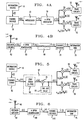
- Figures 4 a and b present the illustrative embodiments of Figures 2 and 3 augmented to include an interleaver/deinterleaver pair, respectively.
- Figure 5 presents a second illustrative embodiment of the present invention.
- Figure 6 presents a receiver for use with the second illustrative embodiment.
- the illustrative embodiments of the present invention concern a wireless communication system such as, e.g. , an indoor radio communication system, a cellular system, or personal communications system.
- a base station commonly uses a plurality of antennas (e.g. , two) for receiving transmitted signals. This plurality of antennas provides the base station with space diversity.
- a plurality of antennas at the base station should be used for the transmission of signals to the mobile units.
- the same plurality of antennas used for base station reception may be used for transmission to the mobile units.
- These mobile units employ but one antenna.
- an indoor radio system comprising a base station having two antennas, T 1 and T 2, for transmitting a channel coded signal in, for example, a Rayleigh fading channel (that is, a channel without a line-of-sight path between transmitter and receiver) and a mobile receiver.
- a channel coded signal in, for example, a Rayleigh fading channel (that is, a channel without a line-of-sight path between transmitter and receiver) and a mobile receiver.
- the typical delay spread between received multipath symbols is on the order of several nanoseconds -- a very small spread in comparison to the duration of a channel code symbol.
- Figure 1 depicts received signal phasors S 1 and S 2, from antennas T 1 and T 2, at specific points in space where a deep fade can occur.
- the signals S 1 and S 2 are independently and identically distributed with, e.g. , Rayleigh amplitude and uniform phase. Furthermore, the characteristics of the channel through which phasors S 1 and S 2 are communicated change slowly, so that the deep fades depicted in Figure 1 are essentially static.
- the deep fades at the locations corresponding to Figure 1(a) occur because of destructive addition of the signals from the two base station antennas.
- the deep fades shown in Figure 1(b) occur because of the weakness of received signal energy from each individual antenna T 1 and T 2.
- the first illustrative embodiment of the present invention introduces very small time varying phase offsets ⁇ 1( n ) and ⁇ 2( n ) to the signals transmitted at antennas T 1 and T 2, respectively. These offsets have the effect of a slow rotation of the phasors S 1 and S 2. If ⁇ 1( n ) and ⁇ 2( n ) take on different values, S 1 and S 2 will destructively interfere with each other only for a small fraction of time. If a channel code is employed, this technique can be used to reduce the deep fades shown in Figure 1(a).
- the first illustrative embodiment may be extended to deal with the deep fades presented in Figure 1(b). All that is required is the use of additional transmitting antennas to help contribute to received signal strength. A discussion of the embodiment below is generic to the number of transmitting antennas, M .
- the second illustrative embodiment introduces phase offsets prior to signal transmission.
- a particular type of channel code -- a block code -- is used. Given the use of this code, the phases of signals transmitted from base station antennas are shifted to take on a set of discrete values which depend on the number of antennas, M , and the length of a block code codeword, N .
- this embodiment addresses both types of deep fades presented in Figure 1, with the deep fade shown in Figure 1(b) addressable by extension to a larger number of transmitting antennas.
- a disclosure of this embodiment is also generic to the number of antennas provided, M , and the number of symbols in a codeword, N .
- the illustrative embodiments of the present invention are presented as comprising individual functional blocks.
- the functions these blocks represent may be provided through the use of either shared or dedicated hardware, including, but not limited to, hardware capable of executing software.
- Illustrative embodiments may comprise digital signal processor (DSP) hardware, such as the AT&T DSP16 or DSP32C, and software performing the operations discussed below.
- DSP digital signal processor
- VLSI Very large scale integration
- a first illustrative embodiment of the present invention is presented in Figure 2.
- the embodiment is a radio communication system base station transmitter for use in, e.g. , cellular radio and other types of personal communications systems.
- the transmitter comprises a channel coder 20, a DPSK modulator 30, a plurality of multiplication circuits 50, transmission circuitry 52 (comprising conventional carrier, pulse shaping, and power amplification circuits), and a plurality of transmitting antennas 55.
- Channel coder 20 may be any of the conventional channel coders well known in the art. These include convolutional or block codes, e.g. , a rate one-half memory 3 convolutional code.
- Coder 20 provides a channel code to a pulse code modulated digital information signal, x ( i ), representing, e.g. , speech.
- Signal x ( i ) is provided by a conventional information source 10 such as, e.g. , an ordinary telephone network, coupled to the base station transmitter, providing signals to be transmitted to a mobile receiver or, more simply, a microphone, audio front-end circuitry, and an analog-to-digital converter in combination. It will be apparent to one of ordinary skill in the art that the present embodiments may be used with any information source which provides or may be adapted to provide digital data.
- Each such symbol, a ( n ) is provided to a conventional 4-DPSK constellation mapper 30 well known in the art.
- Constellation mapper 30 comprises a conventional Gray coded 4-PSK constellation mapper, a multiplier 35, and a unit delay register 37. It will be further apparent to one of ordinary skill in the art that any conventional constellation mapper, or no constellation mapper at all, may be used with these embodiments.
- the results of the operation of the multiplication circuit 35 and delay register 37 are complex 4-DPSK coded symbols, u ( n ).
- This embodiment provides one complex 4-DPSK symbol, u ( n ), for each complex symbol, a ( n ), provided by the channel coder 20.
- Each such symbol, u ( n ) is provided in parallel to a plurality of M multiplication circuits 50, transmission circuitry 52, and transmitting antennas 55.
- M 2.
- Each multiplication circuit 50 multiplies a complex symbol, u ( n ), provided by constellation mapper 30, by a complex time-varying function of the form A m ( n ) e j ⁇ m ( n ) , where m indexes the plurality of M antennas, A m ( n ) is an amplitude weight for the m th antenna, and ⁇ m ( n ) is a phase offset for the m th antenna.
- ⁇ m ⁇ ⁇ [( m - 1)- 1 2 ( M -1)]
- T d is the reciprocal of the transmitted symbol data rate
- multipliers 50 What results from the operation of multipliers 50 are a plurality of complex symbols, c m ( n ), each provided to conventional transmission circuitry 52 and an antenna 55. Signals reflecting symbols c m ( n ) are transmitted substantially simultaneously by antennas 55 to a conventional single antenna receiver equipped with a channel decoder (complementary to channel coder 20).
- the first illustrative embodiment provides for parallel transmission of data symbols by a plurality of M antennas and wherein each symbol is multiplied prior to transmission by a unique complex function.
- FIG 3 presents an illustrative conventional receiver for use with the first illustrative embodiment presented in Figure 2.
- the receiver comprises an antenna 60 and conventional front-end receiver circuitry 62 (comprising, e.g. , low noise amplifiers, RF/IF band-pass filters, and a match filter) for receiving a transmitted signal, s ( n ), from the transmitting antennas 55.
- conventional front-end receiver circuitry 62 comprising, e.g. , low noise amplifiers, RF/IF band-pass filters, and a match filter
- Signal s ( n ) is given by the following expression: where M is the total number of transmitting antennas 55, A m ( n ) and ⁇ m ( n ) are as described above, ⁇ m ( n ) represents the complex fading on each of M multipath channels, u ( n ) is as described above, and ⁇ ( n ) is a complex additive white Gaussian noise component (of course, expression (4) is merely a model for a signal actually received by the receiver; no calculation of expression (4) is needed for purposes of the present invention).
- Signal s ( n ) is provided to a 4-DPSK demodulator 65.
- the output of the 4-DPSK demodulator 65, â ( n ) is an estimate of the output of the channel encoder 20 of the transmitter (the " ⁇ " indicating an estimated value).
- Complex symbol â ( n ) is then provided to conventional channel decoder 70 (complementary to channel coder 20) which provides a decoded information signal estimate, x ⁇ ( i ).
- Information signal estimate, x ⁇ ( i ) is provided to information sink 75 which makes use of the information in any desired manner, such as, e.g. , digital-to-analog conversion, amplification and application to a transducer such as a loudspeaker.
- the first illustrative embodiment of the present invention may be augmented to include a conventional interleaver/deinterleaver pair. See Figure 4 a and b.
- a conventional interleaver/deinterleaver pair in conventional slowly fading systems can result in large transmission delays. This is because to be useful, an interleaver must operate on many symbols ( i.e. , a number of symbols which when multiplied by the reciprocal of the symbol data rate yields a duration far in excess of the duration of an expected fade). For example, assuming a convolutional channel code, the interleaver operates on a number of samples equal to ten times the duration of an expected fade. Thus, a conventional deinterleaver must wait to receive all such symbols before deinterleaving can occur. This causes delay.
- a smaller interleaver/deinterleaver pair may be used, resulting in enhanced performance with less delay than that associated with slowly fading channels.
- the first illustrative embodiment of the present invention may be advantageously combined with conventional multiple antenna receivers providing space (or antenna ) diversity. All that is required of the receiver is that it employ a channel decoder which is complementary to that used in the transmitter.
- an information source 10 presents a digital information signal, x ( i ), for transmission to a receiver.
- the repetition code provided by the channel coder 85 produces a code symbol d ( n ) ⁇ ⁇ -1,1 ⁇ . This symbol is repeated such that the output from coder 85 at time n comprises two symbols, a 1( n ) and a 2( n ), both of which are equal to symbol d ( n ).
- This output, ⁇ ( n ), is provided to multiplier 35 where it is weighted by the output of two symbol unit delay 95.
- each multiplier provides a phase shift, ⁇ m , for the signals to be transmitted at the m th antenna.
- M i.e.
- This phase shift technique provides M uncorrelated symbols and N - M partially decorrelated symbols.
- this embodiment may be augmented with a conventional interleaver/deinterleaver pair.
- the interleaver/deinterleaver pair operates to further decorrelate the N - M partially decorrelated transmitted symbols.
- Each of these multipliers provides an amplitude A m ( l ) of unity.
- the fading coefficients ⁇ 1( n ) and ⁇ 2( n ) are independently and identically distributed complex Gaussian random variables with mean equal to zero.
- values r ( n ) and r ( n +1) are completely uncorrelated.
- FIG 6 presents an illustrative receiver for use with the second illustrative embodiment presented in Figure 5.
- the receiver comprises an antenna 60 and conventional front-end receiver circuitry 62 for receiving a transmitted signal, s ( n ), from the transmitting antennas 55.
- Signal s ( n ) is given by (12).
- Signal s ( n ) is provided to the 4-DPSK demodulator 100.
- the output of the 4-DPSK demodulator 100, â 1,2 ( n ), is an estimate of the output of the channel encoder 85 of the transmitter (the " ⁇ " indicating an estimated value).
- Information signal estimate, x ⁇ ( i ) is provided to information sink 75 which makes use of the information in any desired manner.
- N,M 2.
- r ( n ) and r ( n +1) are uncorrelated as are r ( n +2) and r ( n +3). Values r ( n +2) and r ( n +3) are partially decorrelated from r ( n ) and r ( n +1). Use of a conventional interleaver/deinterleaver pair will render all four of these values approximately uncorrelated.
Abstract
The invention provides a method and apparatus for transmitting digital signal information (10) to a receiver using a plurality of antennas (55,55). The invention involves applying a channel code (20) to a digital signal (x(i)) producing one or more symbols (a(n)). A plurality of symbol copies is made and each copy (u(n)) is weighted (in 50) by a distinct time varying function. Each antenna transmits a signal based on one of the weighted symbol copies (c₁(n) .. C M (n)). Any channel code may be used with the invention, such as a convolutional channel code or block channel code. Weighting provided to symbol copies may involve application of an amplitude gain, phase shift, or both. The present invention may be used in combination with either or both conventional interleavers and constellation mappers.
Description
- The present invention relates generally to the field of communications systems, and particularly to the field of wireless communications, such as, e.g., cellular radio.
- In wireless communication systems, an information signal is communicated from a transmitter to a receiver via a channel comprising several independent paths. These paths are referred to as multipaths. Each multipath represents a distinct route an information signal may take in traveling between the transmitter and receiver. An information signal communicated via such a channel -- a multipath channel -- appears at a receiver as a plurality of multipath signals, one signal for each multipath.
- The amplitudes and phases of signals received from a transmitter through different multipaths of a channel are generally independent of each other. Because of complex addition of multipath signals, the strength of received signals may vary between very small and moderately large values. The phenomenon of received signal strength variation due to complex addition of multipath signals is known as fading. In a fading environment, points of very low signal strength, or deep fades, are separated by approximately one-half of a signal wavelength from each other.
- Wireless communication channels can be described by certain channel characteristics, such as amplitude attenuation and phase shifting. For example, the multipaths of a channel may provide different amplitude attenuations and phase shifts to an information signal communicated from a transmitter to a receiver. These different amplitude and phase characteristics may vary due to, e.g., relative movement between transmitter and receiver, or changes in local geography of the transmitter or receiver due to movement. Because of the variation of channel characteristics, a receiver can experience a signal whose strength varies with time. This variation is the manifestation of the complex addition of multipath signals having time varying amplitudes and phases.
- If the characteristics of a multipath channel vary slowly, a receiver experiencing a deep fade may observe a weak signal for a long period of time. Long fades are not uncommon in, e.g., indoor radio systems, where relative movement between receivers and transmitters is slow or nonexistent (often, one of these two is an immobile base station; the other is a mobile device carried by a person). Since the duration of a deep fade in an indoor radio system may be large in comparison to the duration of information symbols being communicated, long bursts of symbol errors may occur (due to the weakness of received signal strength for an extended period of time).
- Space diversity is a classical technique for mitigating the detrimental effects of fading, such as error bursts. Space diversity is provided through the use of a plurality of antennas at a receiver. If the receiver antennas are separated by more than a couple of wavelengths, the multipath signals received by the individual receiver antennas are approximately independent of each other. When several antennas are used by a receiver, the probability that received signals will yield a deep fade at all antennas simultaneously is small. Thus, signals received by these antennas may be combined to reduce the effects of fading.
- Space diversity, however, is not without its drawbacks. For example, space diversity requires the use of a plurality of widely spaced antennas. For small portable receivers this requirement is problematic. Also, space diversity increases the complexity of a receiver, thereby increasing its cost.
- Time diversity is another technique which has been employed to mitigate the detrimental effects of fading. Time diversity may be achieved by transmitting a plurality of copies of an information signal during distinct time intervals. These transmission time intervals should be separated in time so that received signals are subjected to independent fades. Once the plurality of signal copies have been received by a receiver, the independent nature of their fades facilitates avoidance of the detrimental effects of fading.
- Like space diversity, time diversity also has its drawbacks. Time diversity is predicated on the idea of identical signal transmission at different times. However, the time needed to receive a plurality of copies of an information signal presents a delay in the communication process which may be undesirable, if not intolerable.
- Time diversity can also be effectively obtained when a channel code is used in conjunction with an interleaver/deinterleaver pair well known in the art. An interleaver receives a set of consecutive channel coded data symbols for transmission and rearranges them in, e.g., a pseudorandom fashion. Typically, the number of symbols in the set extend for a duration beyond that of a slow deep fade. Rearranged symbols are transmitted over the channel to a receiver having a single antenna. By virtue of transmission, consecutive symbols are subject to similar fading. However, these consecutively transmitted symbols are not in original order. A receiver equipped with a deinterleaver rearranges the symbols back to their original order. Due to the randomness of their transmission order, data symbols presented to the channel decoder by the deinterleaver have been subject to essentially independent fades. The independent symbol fading afforded by the interleaver/deinterleaver pair may be utilized to avoid fading's detrimental effects.
- However, as with the first time diversity technique discussed above, a transmission delay is created by this approach. This delay is directly proportional to the size of the interleaver. Allowable transmission delay imposes limits on the size of the interleaver. However, an interleaver of a size beyond the imposed limit may be needed to deal effectively with fading.
- The present invention provides a method and apparatus for mitigating the detrimental effects of fading. It does this by effectively varying the characteristics of a multipath communication channel to provide a time diversity with a reduced delay effect.
- A first illustrative embodiment of the present invention provides time diversity by increasing the rate of multipath channel fading. The embodiment further provides information redundancy through use of a channel code. The increased fading rate shortens the duration of fades so as to facilitate avoidance of long error bursts. The redundancy introduced by the channel code helps mitigate errors which may occur due to fading. The embodiment provides a channel coder for applying the channel code to a digital information signal. The channel coder produces one or more coded information symbols which are processed by a constellation mapper. A copy of each symbol is then provided to a plurality of M multipliers. Each multiplier is associated with one of M antennas. The multipliers weight the copies of the symbol with M distinct time varying functions. Illustratively, each of these time varying functions provides a distinct phase offset to a copy of a symbol. The output of each multiplier is provided to its associated antenna for transmission to a receiver. The multiple distinctly weighted copies of a symbol are transmitted substantially simultaneously. The receiver for use with this embodiment comprises a single antenna for receiving the weighted symbols and a channel decoder which is complementary to the channel encoder.
- A second illustrative embodiment of the present invention employs a particular kind of channel code, referred to as a block code. Like the first embodiment, this embodiment employs multipliers such as those described above to weight each of M copies of a block coded symbol, this time with a distinct discrete phase shift. Each weighted copy is provided for transmission to a receiver by an antenna. As with the first embodiment, a receiver for use with this embodiment comprises a single antenna for receiving the weighted symbols and a channel decoder which is complementary to the channel encoder.
- Figure 1 presents two signal phasors from two transmitting antennas at specific points in space where deep fades occur.
- Figure 2 presents a first illustrative embodiment of the present invention.
- Figure 3 presents a receiver for use with the first illustrative embodiment.
- Figures 4 a and b present the illustrative embodiments of Figures 2 and 3 augmented to include an interleaver/deinterleaver pair, respectively.
- Figure 5 presents a second illustrative embodiment of the present invention.
- Figure 6 presents a receiver for use with the second illustrative embodiment.
- The illustrative embodiments of the present invention concern a wireless communication system such as, e.g., an indoor radio communication system, a cellular system, or personal communications system. In such systems, a base station commonly uses a plurality of antennas (e.g., two) for receiving transmitted signals. This plurality of antennas provides the base station with space diversity. According to the principles of the present invention, a plurality of antennas at the base station should be used for the transmission of signals to the mobile units. Advantageously, the same plurality of antennas used for base station reception may be used for transmission to the mobile units. These mobile units employ but one antenna.
- Consider, for example, an indoor radio system comprising a base station having two antennas, T₁ and T₂, for transmitting a channel coded signal in, for example, a Rayleigh fading channel (that is, a channel without a line-of-sight path between transmitter and receiver) and a mobile receiver. In such a system, the typical delay spread between received multipath symbols is on the order of several nanoseconds -- a very small spread in comparison to the duration of a channel code symbol.
- Figure 1 depicts received signal phasors S₁ and S₂, from antennas T₁ and T₂, at specific points in space where a deep fade can occur. The signals S₁ and S₂ are independently and identically distributed with, e.g., Rayleigh amplitude and uniform phase. Furthermore, the characteristics of the channel through which phasors S₁ and S₂ are communicated change slowly, so that the deep fades depicted in Figure 1 are essentially static. The deep fades at the locations corresponding to Figure 1(a) occur because of destructive addition of the signals from the two base station antennas. The deep fades shown in Figure 1(b) occur because of the weakness of received signal energy from each individual antenna T₁ and T₂.
- The first illustrative embodiment of the present invention introduces very small time varying phase offsets ϑ₁(n) and ϑ₂(n) to the signals transmitted at antennas T₁ and T₂, respectively. These offsets have the effect of a slow rotation of the phasors S₁ and S₂. If ϑ₁(n) and ϑ₂(n) take on different values, S₁ and S₂ will destructively interfere with each other only for a small fraction of time. If a channel code is employed, this technique can be used to reduce the deep fades shown in Figure 1(a).
- The first illustrative embodiment may be extended to deal with the deep fades presented in Figure 1(b). All that is required is the use of additional transmitting antennas to help contribute to received signal strength. A discussion of the embodiment below is generic to the number of transmitting antennas, M.
- Like the first illustrative embodiment, the second illustrative embodiment introduces phase offsets prior to signal transmission. In the second embodiment, a particular type of channel code -- a block code -- is used. Given the use of this code, the phases of signals transmitted from base station antennas are shifted to take on a set of discrete values which depend on the number of antennas, M, and the length of a block code codeword, N.
- As with the first illustrative embodiment, this embodiment addresses both types of deep fades presented in Figure 1, with the deep fade shown in Figure 1(b) addressable by extension to a larger number of transmitting antennas. A disclosure of this embodiment is also generic to the number of antennas provided, M, and the number of symbols in a codeword, N.
- For clarity of explanation, the illustrative embodiments of the present invention are presented as comprising individual functional blocks. The functions these blocks represent may be provided through the use of either shared or dedicated hardware, including, but not limited to, hardware capable of executing software. Illustrative embodiments may comprise digital signal processor (DSP) hardware, such as the AT&T DSP16 or DSP32C, and software performing the operations discussed below. Very large scale integration (VLSI) hardware embodiments of the present invention, as well as hybrid DSP/VLSI embodiments, may also be provided.
- A first illustrative embodiment of the present invention is presented in Figure 2. The embodiment is a radio communication system base station transmitter for use in, e.g., cellular radio and other types of personal communications systems. The transmitter comprises a
channel coder 20, aDPSK modulator 30, a plurality ofmultiplication circuits 50, transmission circuitry 52 (comprising conventional carrier, pulse shaping, and power amplification circuits), and a plurality of transmittingantennas 55. -
Channel coder 20 may be any of the conventional channel coders well known in the art. These include convolutional or block codes, e.g., a rate one-half memory 3 convolutional code.Coder 20 provides a channel code to a pulse code modulated digital information signal, x(i), representing, e.g., speech. Signal x(i) is provided by aconventional information source 10 such as, e.g., an ordinary telephone network, coupled to the base station transmitter, providing signals to be transmitted to a mobile receiver or, more simply, a microphone, audio front-end circuitry, and an analog-to-digital converter in combination. It will be apparent to one of ordinary skill in the art that the present embodiments may be used with any information source which provides or may be adapted to provide digital data. - Output from
channel coder 20 are complex data symbols, a(n), where a(n)=a r (n)+ja i (n) and n is a discrete time index; illustratively, a r (n), a i (n)ε {-1,1} (the discrete time index i has been changed to n to reflect the fact that the time indices for information bits and channel coded symbols may not coincide). Each such symbol, a(n), is provided to a conventional 4-DPSK constellation mapper 30 well known in the art.Constellation mapper 30 comprises a conventional Gray coded 4-PSK constellation mapper, amultiplier 35, and aunit delay register 37. It will be further apparent to one of ordinary skill in the art that any conventional constellation mapper, or no constellation mapper at all, may be used with these embodiments. - The 4-
PSK constellation mapper 30 processes complex data symbols a(n) received fromchannel coder 20 as follows:
The Gray coded 4-PSK complex symbols, α(n), are provided tomultiplication circuit 35 where they are multiplied by the output of unit delay register 37 as follows:
- The results of the operation of the
multiplication circuit 35 and delay register 37 are complex 4-DPSK coded symbols, u(n). This embodiment provides one complex 4-DPSK symbol, u(n), for each complex symbol, a(n), provided by thechannel coder 20. Each such symbol, u(n), is provided in parallel to a plurality ofM multiplication circuits 50,transmission circuitry 52, and transmittingantennas 55. Illustratively, M = 2. - Each
multiplication circuit 50 multiplies a complex symbol, u(n), provided byconstellation mapper 30, by a complex time-varying function of the form

where ƒ m = ƒΔ[(m - 1)-
- What results from the operation of
multipliers 50 are a plurality of complex symbols, c m (n), each provided toconventional transmission circuitry 52 and anantenna 55. Signals reflecting symbols c m (n) are transmitted substantially simultaneously byantennas 55 to a conventional single antenna receiver equipped with a channel decoder (complementary to channel coder 20). Thus, the first illustrative embodiment provides for parallel transmission of data symbols by a plurality of M antennas and wherein each symbol is multiplied prior to transmission by a unique complex function. - Figure 3 presents an illustrative conventional receiver for use with the first illustrative embodiment presented in Figure 2. The receiver comprises an
antenna 60 and conventional front-end receiver circuitry 62 (comprising, e.g., low noise amplifiers, RF/IF band-pass filters, and a match filter) for receiving a transmitted signal, s(n), from the transmittingantennas 55. Signal s(n) is given by the following expression:
where M is the total number of transmittingantennas 55, A m (n) and ϑ m (n) are as described above, β m (n) represents the complex fading on each of M multipath channels, u(n) is as described above, and ν(n) is a complex additive white Gaussian noise component (of course, expression (4) is merely a model for a signal actually received by the receiver; no calculation of expression (4) is needed for purposes of the present invention). - Signal s(n) is provided to a 4-
DPSK demodulator 65. The output of the 4-DPSK demodulator 65, â(n), is an estimate of the output of thechannel encoder 20 of the transmitter (the "^" indicating an estimated value).Demodulator 65 provides â(n) according to the following expression:
where s* indicates the complex conjugate of s. Complex symbol â(n) is then provided to conventional channel decoder 70 (complementary to channel coder 20) which provides a decoded information signal estimate, x̂(i). Information signal estimate, x̂(i), is provided to information sink 75 which makes use of the information in any desired manner, such as, e.g., digital-to-analog conversion, amplification and application to a transducer such as a loudspeaker. - The first illustrative embodiment of the present invention may be augmented to include a conventional interleaver/deinterleaver pair. See Figure 4 a and b. As noted previously, use of an interleaver/deinterleaver pair in conventional slowly fading systems can result in large transmission delays. This is because to be useful, an interleaver must operate on many symbols (i.e., a number of symbols which when multiplied by the reciprocal of the symbol data rate yields a duration far in excess of the duration of an expected fade). For example, assuming a convolutional channel code, the interleaver operates on a number of samples equal to ten times the duration of an expected fade. Thus, a conventional deinterleaver must wait to receive all such symbols before deinterleaving can occur. This causes delay.
- By virtue of the faster fading provided by the first illustrative embodiment of present invention, a smaller interleaver/deinterleaver pair may be used, resulting in enhanced performance with less delay than that associated with slowly fading channels.
- The first illustrative embodiment of the present invention may be advantageously combined with conventional multiple antenna receivers providing space (or antenna) diversity. All that is required of the receiver is that it employ a channel decoder which is complementary to that used in the transmitter.
- The second illustrative embodiment of the present invention is presented in Figure 5. As with the first illustrative embodiment of the present invention, an
information source 10 presents a digital information signal, x(i), for transmission to a receiver. Thechannel coder 85 provides an illustrative block code -- e.g., a conventional one-half rate repetition code with block length N = 2. The repetition code provided by thechannel coder 85 produces a code symbol d(n) ε {-1,1}. This symbol is repeated such that the output fromcoder 85 at time n comprises two symbols, a₁(n) and a₂(n), both of which are equal to symbol d(n). - The coded symbols, a₁(n),a₂(n), are mapped to a 4-PSK constellation using a
Gray coder 90. The output ofGray coder 90 is provided according to the following expressions:

- This output, α(n), is provided to
multiplier 35 where it is weighted by the output of twosymbol unit delay 95. This weighting provides 4-DPSK constellation mapping 97 according to the following expression:
The result of 4-DPSK constellation mapping, u(n), is provided to a plurality of M = 2multipliers 50,transmission circuitry 52, and associatedantennas 55. - As a general matter, for a block code wherein each codeword comprises N symbols (with time indices given by n, n + 1, ..., n+N-1), each multiplier provides a phase shift, ϑ m , for the signals to be transmitted at the mth antenna. For up to the first M symbols of a codeword, the phase shift ϑ m applied by the mth multiplier is:

For any symbols of a codeword exceeding M (i.e.,M <N), the phase shift ϑ m applied by the mth multiplier is:
where l is a time index and k and n' are integers which satisfy the following expressions:
- This phase shift technique provides M uncorrelated symbols and N - M partially decorrelated symbols. As with the first embodiment of the present invention, this embodiment may be augmented with a conventional interleaver/deinterleaver pair. In this case, the interleaver/deinterleaver pair operates to further decorrelate the N - M partially decorrelated transmitted symbols.
- For the above second illustrative embodiment, the
first multiplier 50 provides a phase shift ϑ₁(n)=ϑ₁(n+1)=0, while thesecond multiplier 50 provides a phase shift ϑ₂(n)=0 and ϑ₂(n+1)=π. Each of these multipliers provides an amplitude A m (l) of unity. The signal received by a receiver, s, will be of the form:
where β₁(n) and β₂(n) are the complex fading coefficients, ω c is the carrier frequency, T is the sampling interval, and ν(n) is the additive white Gaussian noise component. The fading coefficients β₁(n) and β₂(n) are independently and identically distributed complex Gaussian random variables with mean equal to zero. - The complex envelope of the received signal, s, is

For this embodiment, values r(n) and r(n+1) are completely uncorrelated. - Figure 6 presents an illustrative receiver for use with the second illustrative embodiment presented in Figure 5. The receiver comprises an
antenna 60 and conventional front-end receiver circuitry 62 for receiving a transmitted signal, s(n), from the transmittingantennas 55. Signal s(n) is given by (12). - Signal s(n) is provided to the 4-
DPSK demodulator 100. The output of the 4-DPSK demodulator 100, â 1,2(n), is an estimate of the output of thechannel encoder 85 of the transmitter (the "^" indicating an estimated value).Demodulator 100 provides z(n) according to the following expression:
where s* indicates the complex conjugate of s. Complex symbol z(n) is further processed bydemodulator 100 to provide values for â 1,2(n) as follows:
Values of â 1,2(n) are then provided to channel decoder 110 (complementary to channel coder 85) which provides a decoded information signal estimate, x̂(i) by (i) forming a value U(n)=â₁(n)+â₂(n); (ii) determining â(n) as follows:
and (iii) conventionally decoding d̂(n) to provide x̂(i). Information signal estimate, x̂(i), is provided to information sink 75 which makes use of the information in any desired manner. - The above discussion of the second embodiment includes an example where N,M = 2. The generality of equations (9)-(11) may further be seen when N>M. For example, assuming , N = 4 and M = 2, the
first multiplier 50 provides no phase shift (i.e., u(n) multiplied by unity), and the second multiplier provides phase shift for each block of ϑ₂(n)=0; ϑ₂(n+1)=π; ϑ₂(n+2)=π/2; and ϑ₂(n+3)=3π/2. In this case, the signal received by a receiver, s, will be of the form:
The complex envelope of the received signal is
According to this particular embodiment (where N = 4 and M = 2), r(n) and r(n+1) are uncorrelated as are r(n+2) and r(n+3). Values r(n+2) and r(n+3) are partially decorrelated from r(n) and r(n+1). Use of a conventional interleaver/deinterleaver pair will render all four of these values approximately uncorrelated. In a very slow fading channel in the absence of phase variations provided in accordance with the present invention, all four of these values, r(n), r(n+1), r(n+2), and r(n+3), will be highly correlated and will require an interleaver of large dimension. By use of the present embodiment, only two of the four values need decorrelation by operation of an interleaver. Thus, the delay due to interleaving may be reduced by more than a factor of two.
Claims (17)
- A method of transmitting digital signal information to a receiver with use of a plurality of M antennas (55), the method comprising the steps of:
applying a channel code to a digital signal (x(i)) to produce one or more symbols (a(n)),
forming M copies of a symbol;
weighting each of the M symbol copies (u(n)) with M distinct time varying functions; and
substantially simultaneously transmitting M signals (c₁(m)...(C M (n)) with M different antennas, each transmitted signal based on a distinct one of the M weighted symbol copies. - A method as claimed in claim 1 wherein the step of applying a channel code comprises the step of applying a convolutional code, or the step of applying a block code.
- A method as claimed in claim 1 wherein each time varying function provides an amplitude gain to a symbol, or provides a phase shift to a symbol.
- A method as claimed in claim 3 wherein the amplitude gain is

- A method as claimed in claim 3 wherein a phase shift applied to symbols is based upon the transmitted symbol data rate.
- A method as claimed in claim 3 wherein a phase shift spplied to an nth symbol for the mth antenna is 2πƒΔ[(m-1)-

- A method as claimed in claim 3 wherein a phase shift, Θ m (1), applied to an nth symbol for the mth antenna is

or

where k and n' are integers which satisfy the following expressions:
(k-1)M+1≦N≦kM
and
n'(k-1)<(l-M-n+1)≦(n'+1)(k-1). - A method as claimed in claim 1 comprising the step of processing a plurality of symbols with an interleaver (25).
- A method as claimed in claim 1 comprising the step of processing a symbol with a constellation mapper (30).
- A transmitter for a wireless communication system for transmitting signals to a receiver, the transmitter comprising:
a channel coder (20) for receiving a digital information signal (x(i)) and producing one or more symbols (a(n)) based on said signal:
a plurality of M information symbol weighting means (50), coupled to the channel coder, each such means for weighting a symbol with a distinct time varying function;
a plurality of M antennas (55), each coupled to a symbol weighting means, for transmitting substantially simultaneously M signals based on a weighted symbol. - A transmitter as claimed in claim 10 wherein the signals for transmission to a receiver are provided to the transmitter by an information source (10) comprising a telephone network.
- A transmitter as claimed in claim 10 wherein the channel coder comprises a convolutional channel coder, or a block code channel coder.
- A transmitter as claimed in claim 10 wherein one or more of the symbol weighting means comprise a multiplier applying the time varying function.
- A transmitter as claimed in claim 10 wherein the time varying function provides a phase shift to a symbol, or provides an amplitude gain to a symbol.
- A transmitter as claimed in claim 10 comprising a constellation mapper (30), coupled to receive symbols (a(n)) and to provide mapped symbols (u(m)) to the plurality of weighting means.
- A method as claimed in claim 9 or a transmitter as claimed in claim 15 wherein the constellation mapper comprises a PSK constellation mapper, or a DPSK constellation mapper.
- A transmitter as claimed in claim 10 comprising an interleaver (25), coupled to the channel coder, for producing a plurality of interleaved symbols (a'(n)).
Applications Claiming Priority (2)
| Application Number | Priority Date | Filing Date | Title |
|---|---|---|---|
| US890977 | 1992-05-29 | ||
| US07/890,977 US5305353A (en) | 1992-05-29 | 1992-05-29 | Method and apparatus for providing time diversity |
Publications (1)
| Publication Number | Publication Date |
|---|---|
| EP0572171A1 true EP0572171A1 (en) | 1993-12-01 |
Family
ID=25397412
Family Applications (1)
| Application Number | Title | Priority Date | Filing Date |
|---|---|---|---|
| EP93303908A Withdrawn EP0572171A1 (en) | 1992-05-29 | 1993-05-20 | Method and apparatus for providing time diversity for multipath fading channels |
Country Status (4)
| Country | Link |
|---|---|
| US (2) | US5305353A (en) |
| EP (1) | EP0572171A1 (en) |
| JP (1) | JP2859513B2 (en) |
| CA (1) | CA2094193C (en) |
Cited By (15)
| Publication number | Priority date | Publication date | Assignee | Title |
|---|---|---|---|---|
| EP0605119A2 (en) * | 1992-12-29 | 1994-07-06 | AT&T Corp. | Diversity for direct-sequence spread spectrum systems |
| EP0736979A2 (en) * | 1995-04-03 | 1996-10-09 | AT&T IPM Corp. | Fast fading packet diversity transmission method and system |
| EP0739554A1 (en) * | 1994-01-12 | 1996-10-30 | Bell Communications Research, Inc. | Tetherless access to communication networks |
| EP0744841A2 (en) * | 1995-05-24 | 1996-11-27 | Sony Corporation | Method and apparatus for transmission and reception of burst signals using time diversity and antenna switching |
| WO1997009812A1 (en) * | 1995-09-07 | 1997-03-13 | Robert Bosch Gmbh | Process for transferring digital data via interference-affected radio channels and device for receiving digital data transmitted via interference-affected radio channels |
| EP0767546A2 (en) * | 1995-10-04 | 1997-04-09 | AT&T Corp. | Method and apparatus for providing time diversity using multiple base stations |
| EP0796024A2 (en) * | 1994-11-28 | 1997-09-17 | Texas Instruments Incorporated | Low power, short range point-to-multipoint communications system |
| WO2000011844A1 (en) * | 1998-08-18 | 2000-03-02 | Fraunhofer-Gesellschaft zur Förderung der angewandten Forschung e.V. | Method and device for transmitting information symbols using a plurality of carriers and method and device for receiving information symbols |
| WO2000036783A1 (en) * | 1998-12-03 | 2000-06-22 | Fraunhofer-Gesellschaft zur Förderung der angewandten Forschung e.V. | Apparatus and method for transmitting information and apparatus and method for receiving information |
| US6122622A (en) * | 1998-02-18 | 2000-09-19 | H. B. Fuller | Computer aided system for compliance with chemical control laws |
| EP1294120A1 (en) * | 2001-09-13 | 2003-03-19 | Texas Instruments Incorporated | Hybrid ARQ in MIMO systems using basis hopping for retransmissions |
| US6553239B1 (en) | 1995-06-07 | 2003-04-22 | Cisco Technology, Inc. | Low power, short range point-to-multipoint communications system |
| WO2003085858A1 (en) * | 2002-04-01 | 2003-10-16 | Qualcomm Incorporated | Method and apparatus for transmit power modulation in a wireless communication system |
| GB2409617A (en) * | 2003-12-23 | 2005-06-29 | Toshiba Res Europ Ltd | Multiplying data for static MIMO/MISO channels by time varying function to improve reception |
| US8209575B2 (en) | 2002-08-28 | 2012-06-26 | Texas Instruments Incorporated | MIMO hybrid-ARQ using basis hopping |
Families Citing this family (75)
| Publication number | Priority date | Publication date | Assignee | Title |
|---|---|---|---|---|
| US5479448A (en) * | 1992-03-31 | 1995-12-26 | At&T Corp. | Method and apparatus for providing antenna diversity |
| EP0622910B1 (en) * | 1993-04-29 | 2003-06-25 | Ericsson Inc. | Time diversity transmission system for the reduction of adjacent channel interference in mobile telephone systems |
| DE4329898A1 (en) | 1993-09-04 | 1995-04-06 | Marcus Dr Besson | Wireless medical diagnostic and monitoring device |
| CA2118355C (en) * | 1993-11-30 | 2002-12-10 | Michael James Gans | Orthogonal polarization and time varying offsetting of signals for digital data transmission or reception |
| US5566209A (en) * | 1994-02-10 | 1996-10-15 | Telefonaktiebolaget Lm Ericsson | Transceiver algorithms of antenna arrays |
| US5625881A (en) * | 1994-04-28 | 1997-04-29 | Bell-Northern Research Ltd. | Time and frequency diveristy in a radio system having intermittent operation receivers |
| DE4427755A1 (en) * | 1994-08-05 | 1996-02-08 | Sel Alcatel Ag | Fixed or mobile radio station for an SDMA mobile radio system |
| US5614914A (en) | 1994-09-06 | 1997-03-25 | Interdigital Technology Corporation | Wireless telephone distribution system with time and space diversity transmission for determining receiver location |
| US5719883A (en) * | 1994-09-21 | 1998-02-17 | Lucent Technologies Inc. | Adaptive ARQ/FEC technique for multitone transmission |
| US5559788A (en) * | 1994-12-29 | 1996-09-24 | Unisys Corporation | Multiple channel quadrature communication system and method |
| JPH08195703A (en) * | 1995-01-17 | 1996-07-30 | Toshiba Corp | Radio communication equipment |
| US5689439A (en) * | 1995-03-31 | 1997-11-18 | Lucent Technologies, Inc. | Switched antenna diversity transmission method and system |
| US5671156A (en) * | 1995-03-31 | 1997-09-23 | Lucent Technologies Inc. | Transmission method and system for JPEG images |
| JP2746190B2 (en) * | 1995-04-27 | 1998-04-28 | 住友電気工業株式会社 | Spread spectrum communication equipment |
| US5767791A (en) * | 1995-11-13 | 1998-06-16 | Vitalcom | Low-power circuit and method for providing rapid frequency lock in a wireless communications device |
| CA2186793C (en) * | 1995-11-13 | 2000-12-19 | Vijitha Weerackody | Method and apparatus to implement antenna diversity for direct sequence spread spectrum receivers |
| US5944659A (en) * | 1995-11-13 | 1999-08-31 | Vitalcom Inc. | Architecture for TDMA medical telemetry system |
| JP3336836B2 (en) * | 1995-11-28 | 2002-10-21 | 三菱電機株式会社 | Synchronization determination circuit, demodulator and communication system |
| US6014570A (en) * | 1995-12-18 | 2000-01-11 | The Board Of Trustees Of The Leland Stanford Junior University | Efficient radio signal diversity combining using a small set of discrete amplitude and phase weights |
| US5960039A (en) * | 1996-04-10 | 1999-09-28 | Lucent Technologies Inc. | Methods and apparatus for high data rate transmission in narrowband mobile radio channels |
| CA2252664C (en) * | 1996-04-26 | 2002-04-02 | At&T Corp. | Method and apparatus for data transmission using multiple transmit antennas |
| JPH1066039A (en) * | 1996-08-23 | 1998-03-06 | Sony Corp | Communication method, transmitter, transmission method, receiver and reception method |
| US5838267A (en) * | 1996-10-09 | 1998-11-17 | Ericsson, Inc. | Method and apparatus for encoding and decoding digital information |
| US6044485A (en) * | 1997-01-03 | 2000-03-28 | Ericsson Inc. | Transmitter method and transmission system using adaptive coding based on channel characteristics |
| US5933421A (en) | 1997-02-06 | 1999-08-03 | At&T Wireless Services Inc. | Method for frequency division duplex communications |
| US5875208A (en) * | 1997-02-06 | 1999-02-23 | At&T Wireless Services, Inc | Delay compensation in a discrete multitone spread spectrum communications system |
| US6501771B2 (en) | 1997-02-11 | 2002-12-31 | At&T Wireless Services, Inc. | Delay compensation |
| US6408016B1 (en) | 1997-02-24 | 2002-06-18 | At&T Wireless Services, Inc. | Adaptive weight update method and system for a discrete multitone spread spectrum communications system |
| US6359923B1 (en) * | 1997-12-18 | 2002-03-19 | At&T Wireless Services, Inc. | Highly bandwidth efficient communications |
| US6584144B2 (en) | 1997-02-24 | 2003-06-24 | At&T Wireless Services, Inc. | Vertical adaptive antenna array for a discrete multitone spread spectrum communications system |
| GB9715396D0 (en) * | 1997-07-23 | 1997-09-24 | Philips Electronics Nv | Radio communication system |
| US6038263A (en) * | 1997-07-31 | 2000-03-14 | Motorola, Inc. | Method and apparatus for transmitting signals in a communication system |
| US6185258B1 (en) * | 1997-09-16 | 2001-02-06 | At&T Wireless Services Inc. | Transmitter diversity technique for wireless communications |
| US6026132A (en) * | 1997-09-29 | 2000-02-15 | Lucent Technologies, Inc. | Method and apparatus for mitigating the effects of rayleigh fading at low vehicle speeds |
| JP3316744B2 (en) | 1997-10-30 | 2002-08-19 | 三菱電機株式会社 | AFC circuit, receiver having the same, and automatic frequency control communication system |
| CA2276207C (en) * | 1997-10-31 | 2003-02-18 | At&T Wireless Services, Inc. | Low complexity maximum likelihood detection of concatenated space codes for wireless applications |
| US6088408A (en) | 1998-11-06 | 2000-07-11 | At & T Corp. | Decoding for generalized orthogonal designs for space-time codes for wireless communication |
| US6188736B1 (en) * | 1997-12-23 | 2001-02-13 | At&T Wireless Svcs. Inc. | Near-optimal low-complexity decoding of space-time codes for fixed wireless applications |
| US7733966B2 (en) * | 1997-12-30 | 2010-06-08 | Summit Technology Systems, Lp | System and method for space diversified linear block interleaving |
| BR9912631A (en) * | 1998-07-31 | 2001-05-02 | Ericsson Inc | Communications apparatus and process for combining transmitter signals from a fixed cellular station in free space |
| US6487235B2 (en) | 1998-08-24 | 2002-11-26 | At&T Wireless Services, Inc. | Delay compensation |
| US6459740B1 (en) * | 1998-09-17 | 2002-10-01 | At&T Wireless Services, Inc. | Maximum ratio transmission |
| US6643338B1 (en) * | 1998-10-07 | 2003-11-04 | Texas Instruments Incorporated | Space time block coded transmit antenna diversity for WCDMA |
| US6804304B1 (en) * | 1998-10-30 | 2004-10-12 | Broadcom Corporation | Reduction of aggregate EMI emissions of multiple transmitters |
| AU1330200A (en) | 1998-10-30 | 2000-05-22 | Broadcom Corporation | Internet gigabit ethernet transmitter architecture |
| KR100442607B1 (en) * | 1999-02-04 | 2004-08-02 | 삼성전자주식회사 | Appratus and method for spreading channel in cdma communication system |
| US6823483B1 (en) * | 1999-04-22 | 2004-11-23 | Broadcom Corporation | Physical coding sublayer for a multi-pair gigabit transceiver |
| US7058086B2 (en) | 1999-05-26 | 2006-06-06 | Xm Satellite Radio Inc. | Method and apparatus for concatenated convolutional encoding and interleaving |
| US6154452A (en) * | 1999-05-26 | 2000-11-28 | Xm Satellite Radio Inc. | Method and apparatus for continuous cross-channel interleaving |
| US6229824B1 (en) | 1999-05-26 | 2001-05-08 | Xm Satellite Radio Inc. | Method and apparatus for concatenated convolutional endcoding and interleaving |
| US6285720B1 (en) * | 1999-05-28 | 2001-09-04 | W J Communications, Inc. | Method and apparatus for high data rate wireless communications over wavefield spaces |
| US6564003B2 (en) * | 1999-11-04 | 2003-05-13 | Xm Satellite Radio Inc. | Method and apparatus for composite data stream storage and playback |
| US6807145B1 (en) | 1999-12-06 | 2004-10-19 | Lucent Technologies Inc. | Diversity in orthogonal frequency division multiplexing systems |
| US7062245B2 (en) * | 1999-12-21 | 2006-06-13 | Matsushita Electric Industrial Co., Ltd. | Radio transmission apparatus and radio reception apparatus |
| US6377632B1 (en) | 2000-01-24 | 2002-04-23 | Iospan Wireless, Inc. | Wireless communication system and method using stochastic space-time/frequency division multiplexing |
| US6496705B1 (en) * | 2000-04-18 | 2002-12-17 | Motorola Inc. | Programmable wireless electrode system for medical monitoring |
| US6441747B1 (en) * | 2000-04-18 | 2002-08-27 | Motorola, Inc. | Wireless system protocol for telemetry monitoring |
| CA2414309C (en) * | 2000-07-18 | 2006-10-31 | Motorola, Inc. | Wireless electrocardiograph system and method |
| US6694147B1 (en) * | 2000-09-15 | 2004-02-17 | Flarion Technologies, Inc. | Methods and apparatus for transmitting information between a basestation and multiple mobile stations |
| US20020111142A1 (en) * | 2000-12-18 | 2002-08-15 | Klimovitch Gleb V. | System, apparatus, and method of estimating multiple-input multiple-output wireless channel with compensation for phase noise and frequency offset |
| JP4731055B2 (en) * | 2001-06-29 | 2011-07-20 | パナソニック株式会社 | Wireless communication apparatus and wireless communication method |
| US20040127802A1 (en) * | 2001-07-17 | 2004-07-01 | Gmp Companies, Inc. | Wireless ECG system |
| US7933642B2 (en) * | 2001-07-17 | 2011-04-26 | Rud Istvan | Wireless ECG system |
| US20030109282A1 (en) * | 2001-12-06 | 2003-06-12 | Itzhak Shperling | Method and base station for providing phase-shift transmit diversity |
| JP2003249918A (en) * | 2002-02-25 | 2003-09-05 | Matsushita Electric Ind Co Ltd | Receiver and receiving method |
| US7412011B2 (en) * | 2003-08-29 | 2008-08-12 | Texas Instruments Incorporated | Joint ratio estimation and weights detection in closed loop transmit diversity |
| US8527855B2 (en) * | 2004-08-16 | 2013-09-03 | Koninklijke Philips N.V. | Interleaving and parsing for MIMO-OFDM systems |
| US7885617B2 (en) | 2004-11-02 | 2011-02-08 | Ntt Docomo, Inc. | Base station, radio line control station, and radio communication method |
| US20060237384A1 (en) * | 2005-04-20 | 2006-10-26 | Eric Neumann | Track unit with removable partitions |
| EP1949558B1 (en) * | 2005-10-05 | 2015-01-14 | Telecom Italia S.p.A. | Method and system for multiple antenna communications, related apparatus and corresponding computer program product |
| CN101257362B (en) * | 2007-02-27 | 2011-01-19 | 展讯通信(上海)有限公司 | Broadcast service external forward error correction encoding apparatus and method based on TD-SCDMA network |
| US8194623B2 (en) * | 2008-06-27 | 2012-06-05 | Ntt Docomo, Inc. | Evolving-type user resource structure/channelization with enhanced diversity for OFDMA based time-varying channels |
| US8737506B1 (en) | 2010-12-29 | 2014-05-27 | Sprint Communications Company L.P. | Determination of transmit diversity transmission delays |
| US8437713B1 (en) | 2011-02-16 | 2013-05-07 | Sprint Communications Company L.P. | Wireless transmit diversity control by location of a wireless communication device |
| US8565686B2 (en) | 2011-06-30 | 2013-10-22 | Sprint Communications Company L.P. | Power status multipath search window sizing for wireless communications |
Citations (1)
| Publication number | Priority date | Publication date | Assignee | Title |
|---|---|---|---|---|
| EP0419429A1 (en) * | 1989-09-12 | 1991-03-27 | Telefonaktiebolaget L M Ericsson | Method of reducing the risk for poor reception in a time multiplexed radio communication system |
Family Cites Families (7)
| Publication number | Priority date | Publication date | Assignee | Title |
|---|---|---|---|---|
| US3125724A (en) * | 1964-03-17 | Transmitting | ||
| US3252093A (en) * | 1961-10-09 | 1966-05-17 | Massachusetts Inst Technology | Impulse noise suppression communication system utilizing matched filters and noise clipping |
| US3267380A (en) * | 1962-10-19 | 1966-08-16 | Sichak Associates | Diversity phase control system using subcarrier identifying signals |
| US3348150A (en) * | 1964-07-27 | 1967-10-17 | Bell Telephone Labor Inc | Diversity transmission system |
| US3662268A (en) * | 1970-11-17 | 1972-05-09 | Bell Telephone Labor Inc | Diversity communication system using distinct spectral arrangements for each branch |
| US3717814A (en) * | 1971-09-23 | 1973-02-20 | Bell Telephone Labor Inc | Cophasing diversity communication system with pilot feedback |
| US5084669A (en) * | 1990-03-08 | 1992-01-28 | Telefonaktiebolaget L M Ericsson | Direct phase digitization |
-
1992
- 1992-05-29 US US07/890,977 patent/US5305353A/en not_active Expired - Lifetime
-
1993
- 1993-04-16 CA CA002094193A patent/CA2094193C/en not_active Expired - Fee Related
- 1993-05-20 EP EP93303908A patent/EP0572171A1/en not_active Withdrawn
- 1993-05-20 JP JP5139895A patent/JP2859513B2/en not_active Expired - Lifetime
-
1994
- 1994-02-25 US US08/201,832 patent/US5457712A/en not_active Expired - Lifetime
Patent Citations (1)
| Publication number | Priority date | Publication date | Assignee | Title |
|---|---|---|---|---|
| EP0419429A1 (en) * | 1989-09-12 | 1991-03-27 | Telefonaktiebolaget L M Ericsson | Method of reducing the risk for poor reception in a time multiplexed radio communication system |
Non-Patent Citations (3)
| Title |
|---|
| IEEE TRANSACTIONS ON VEHICULAR TECHNOLOGY vol. 28, no. 4, November 1979, NEW YORK US pages 333 - 338 F.ADACHI 'TRANSMITTER DIVERSITY FOR A DIGITAL FM PAGING SYSTEM' * |
| NAMBI SESHADRI, SUNDBERG C. E. W.: "MULTI-LEVEL BLOCK CODED MODULATIONS FOR THE RAYLEIGH FADING CHANNEL.", COUNTDOWN TO THE NEW MILENNIUM. PHOENIX, DEC. 2 - 5, 1991., NEW YORK, IEEE., US, vol. 01 OF 03., 2 December 1991 (1991-12-02), US, pages 47 - 51., XP000325945, ISBN: 978-0-87942-697-2 * |
| TRANSACTIONS OF THE INSTITUTE OF ELECTRONICS AND COMMUNICATION ENGINEERS OF JAPAN, SECTION E vol. 64, no. 8, August 1981, TOKYO JP pages 544 - 550 K.HIRADE ET AL. 'A NEW TRANSMITTER DIVERSITY FOR MSK LAND MOBILE RADIO' * |
Cited By (31)
| Publication number | Priority date | Publication date | Assignee | Title |
|---|---|---|---|---|
| EP0605119A3 (en) * | 1992-12-29 | 1995-05-10 | At & T Corp | Diversity for direct-sequence spread spectrum systems. |
| EP0605119A2 (en) * | 1992-12-29 | 1994-07-06 | AT&T Corp. | Diversity for direct-sequence spread spectrum systems |
| EP0739554A1 (en) * | 1994-01-12 | 1996-10-30 | Bell Communications Research, Inc. | Tetherless access to communication networks |
| EP0739554A4 (en) * | 1994-01-12 | 2000-07-12 | Telcordia Tech Inc | Tetherless access to communication networks |
| EP0796024A3 (en) * | 1994-11-28 | 1999-05-19 | Texas Instruments Incorporated | Low power, short range point-to-multipoint communications system |
| US6101174A (en) * | 1994-11-28 | 2000-08-08 | Texas Instruments Incorporated | Low power, short range point-to-multipoint communications systems |
| US6006069A (en) * | 1994-11-28 | 1999-12-21 | Bosch Telecom Gmbh | Point-to-multipoint communications system |
| EP0796024A2 (en) * | 1994-11-28 | 1997-09-17 | Texas Instruments Incorporated | Low power, short range point-to-multipoint communications system |
| EP0736979A3 (en) * | 1995-04-03 | 2000-04-19 | AT&T IPM Corp. | Fast fading packet diversity transmission method and system |
| EP0736979A2 (en) * | 1995-04-03 | 1996-10-09 | AT&T IPM Corp. | Fast fading packet diversity transmission method and system |
| EP0744841A3 (en) * | 1995-05-24 | 1999-09-29 | Sony Corporation | Method and apparatus for transmission and reception of burst signals using time diversity and antenna switching |
| EP0744841A2 (en) * | 1995-05-24 | 1996-11-27 | Sony Corporation | Method and apparatus for transmission and reception of burst signals using time diversity and antenna switching |
| US6553239B1 (en) | 1995-06-07 | 2003-04-22 | Cisco Technology, Inc. | Low power, short range point-to-multipoint communications system |
| WO1997009812A1 (en) * | 1995-09-07 | 1997-03-13 | Robert Bosch Gmbh | Process for transferring digital data via interference-affected radio channels and device for receiving digital data transmitted via interference-affected radio channels |
| EP0767546A2 (en) * | 1995-10-04 | 1997-04-09 | AT&T Corp. | Method and apparatus for providing time diversity using multiple base stations |
| EP0767546A3 (en) * | 1995-10-04 | 2000-04-19 | AT&T Corp. | Method and apparatus for providing time diversity using multiple base stations |
| US6122622A (en) * | 1998-02-18 | 2000-09-19 | H. B. Fuller | Computer aided system for compliance with chemical control laws |
| WO2000011844A1 (en) * | 1998-08-18 | 2000-03-02 | Fraunhofer-Gesellschaft zur Förderung der angewandten Forschung e.V. | Method and device for transmitting information symbols using a plurality of carriers and method and device for receiving information symbols |
| US7173979B1 (en) | 1998-08-18 | 2007-02-06 | Fraunhofer-Gesellschaft Zur Foerderung Der Angewandten Forschung E.V. | Method and device for transmitting information symbols using a plurality of carriers and method and device for receiving information symbols |
| WO2000036783A1 (en) * | 1998-12-03 | 2000-06-22 | Fraunhofer-Gesellschaft zur Förderung der angewandten Forschung e.V. | Apparatus and method for transmitting information and apparatus and method for receiving information |
| US6314289B1 (en) | 1998-12-03 | 2001-11-06 | Fraunhofer-Gesellschaft zur Förderung der angewandten Forschung e.V. | Apparatus and method for transmitting information and apparatus and method for receiving information |
| EP1294120A1 (en) * | 2001-09-13 | 2003-03-19 | Texas Instruments Incorporated | Hybrid ARQ in MIMO systems using basis hopping for retransmissions |
| US7447967B2 (en) | 2001-09-13 | 2008-11-04 | Texas Instruments Incorporated | MIMO hybrid-ARQ using basis hopping |
| KR100949251B1 (en) * | 2001-09-13 | 2010-03-25 | 텍사스 인스트루먼츠 인코포레이티드 | Mimo hybrid-arq using basis hopping |
| US7698616B2 (en) | 2001-09-13 | 2010-04-13 | Texas Instruments Incorporated | MIMO Hybrid-ARQ using basis hopping |
| WO2003085858A1 (en) * | 2002-04-01 | 2003-10-16 | Qualcomm Incorporated | Method and apparatus for transmit power modulation in a wireless communication system |
| US6873831B2 (en) | 2002-04-01 | 2005-03-29 | Qualcomm Incorporated | Method and apparatus for transmit power modulation in a wireless communications system |
| KR100898891B1 (en) * | 2002-04-01 | 2009-05-21 | 퀄컴 인코포레이티드 | Method and apparatus for transmit power modulation in a wireless communication system |
| US8209575B2 (en) | 2002-08-28 | 2012-06-26 | Texas Instruments Incorporated | MIMO hybrid-ARQ using basis hopping |
| GB2409617A (en) * | 2003-12-23 | 2005-06-29 | Toshiba Res Europ Ltd | Multiplying data for static MIMO/MISO channels by time varying function to improve reception |
| GB2409617B (en) * | 2003-12-23 | 2006-07-12 | Toshiba Res Europ Ltd | Data encoding for static mimo channels |
Also Published As
| Publication number | Publication date |
|---|---|
| CA2094193C (en) | 1998-08-25 |
| CA2094193A1 (en) | 1993-11-30 |
| JP2859513B2 (en) | 1999-02-17 |
| JPH0637683A (en) | 1994-02-10 |
| US5305353A (en) | 1994-04-19 |
| US5457712A (en) | 1995-10-10 |
Similar Documents
| Publication | Publication Date | Title |
|---|---|---|
| EP0572171A1 (en) | Method and apparatus for providing time diversity for multipath fading channels | |
| US5848103A (en) | Method and apparatus for providing time diversity | |
| EP0566257B1 (en) | Method and apparatus for providing antenna diversity | |
| EP1003297B1 (en) | Transmit diversity and reception equalization for radio links | |
| EP0422467B1 (en) | HF high data rate modem | |
| EP1172944B1 (en) | Wireless transmitter and receiver | |
| EP0894388B1 (en) | Pilot-symbol-assisted radiotelephone communications | |
| US7613259B2 (en) | Mobile receiver phase correction circuit | |
| US20030067993A1 (en) | Open-loop diversity technique for systems employing multi-transmitter antennas | |
| EP0989688B1 (en) | Spread spectrum diversity transmitter/receiver | |
| US20050254445A1 (en) | Receiver and method of operation thereof | |
| US20040114693A1 (en) | Apparatus and method for estimation of frequency offset in wireless communications | |
| CN100590985C (en) | Multilayer carrier discrete multitone communication technology | |
| CN101860391B (en) | Multilayer-carrier discrete multi-tone communication technology | |
| JP4094401B2 (en) | Radio communication system transmitter and radio communication system | |
| CN102983893B (en) | Multilayer-carrier discrete multi-tone communication system and method | |
| WO2002003641A1 (en) | Cofdm transmitter with diversity and time delay | |
| MXPA00000536A (en) | Communication system and method with orthogonal block encoding |
Legal Events
| Date | Code | Title | Description |
|---|---|---|---|
| PUAI | Public reference made under article 153(3) epc to a published international application that has entered the european phase |
Free format text: ORIGINAL CODE: 0009012 |
|
| AK | Designated contracting states |
Kind code of ref document: A1 Designated state(s): DE ES FR GB IT |
|
| RAP3 | Party data changed (applicant data changed or rights of an application transferred) |
Owner name: AT&T CORP. |
|
| 17P | Request for examination filed |
Effective date: 19940519 |
|
| 17Q | First examination report despatched |
Effective date: 19970507 |
|
| STAA | Information on the status of an ep patent application or granted ep patent |
Free format text: STATUS: THE APPLICATION HAS BEEN WITHDRAWN |
|
| 18W | Application withdrawn |
Withdrawal date: 19970816 |