EP0571307A1 - Self-assembly of cable duct pieces and method of manufacture - Google Patents
Self-assembly of cable duct pieces and method of manufacture Download PDFInfo
- Publication number
- EP0571307A1 EP0571307A1 EP93460020A EP93460020A EP0571307A1 EP 0571307 A1 EP0571307 A1 EP 0571307A1 EP 93460020 A EP93460020 A EP 93460020A EP 93460020 A EP93460020 A EP 93460020A EP 0571307 A1 EP0571307 A1 EP 0571307A1
- Authority
- EP
- European Patent Office
- Prior art keywords
- section
- cable tray
- gutter
- coupling member
- constituted
- Prior art date
- Legal status (The legal status is an assumption and is not a legal conclusion. Google has not performed a legal analysis and makes no representation as to the accuracy of the status listed.)
- Granted
Links
Images

Classifications
-
- H—ELECTRICITY
- H02—GENERATION; CONVERSION OR DISTRIBUTION OF ELECTRIC POWER
- H02G—INSTALLATION OF ELECTRIC CABLES OR LINES, OR OF COMBINED OPTICAL AND ELECTRIC CABLES OR LINES
- H02G3/00—Installations of electric cables or lines or protective tubing therefor in or on buildings, equivalent structures or vehicles
- H02G3/02—Details
- H02G3/06—Joints for connecting lengths of protective tubing or channels, to each other or to casings, e.g. to distribution boxes; Ensuring electrical continuity in the joint
- H02G3/0608—Joints for connecting non cylindrical conduits, e.g. channels
-
- H—ELECTRICITY
- H02—GENERATION; CONVERSION OR DISTRIBUTION OF ELECTRIC POWER
- H02G—INSTALLATION OF ELECTRIC CABLES OR LINES, OR OF COMBINED OPTICAL AND ELECTRIC CABLES OR LINES
- H02G3/00—Installations of electric cables or lines or protective tubing therefor in or on buildings, equivalent structures or vehicles
- H02G3/02—Details
- H02G3/04—Protective tubing or conduits, e.g. cable ladders or cable troughs
- H02G3/0437—Channels
- H02G3/0443—Channels formed by wire or analogous netting
Definitions
- the present invention relates to the production of gutter-shaped structures for supporting and guiding cables such as, for example, electric cables, telephone cables, fiber optic cables, computer network cables or any similar flexible pipes.
- These structures are designated by the term of cable trays and are produced by the assembly of different sections having a variable length and width depending on the number of cables to be laid inside the gutter they form and of the length of the path to travel.
- the sections constituting these cable trays are conventionally made up of perforated sheet structures in order to lighten them or by lattices of mechanically welded steel wires. In order to resist corrosion, these metallic structures generally undergo a surface treatment of conventional invoice such as a coating of paint, zinc plating or hot galvanization. The use of stainless steel is sometimes necessary to combat the most aggressive atmospheres.
- These sections can also be made of composite materials such as reinforced polyester.
- the sections of cable tray made from warp and weft wires organized in lattices are generally formed by flat welding of the wires together. This welding is carried out in gauges having a variable dimensioning as a function of the size of the section which it is desired to obtain. Once this welding operation has been carried out, the lattice is deformed by folding or bending, so as to take the form of a gutter.
- a complete cable tray is produced by assembling a determined number of these sections, as a function of the length of the path to be covered by the cables.
- the main problem posed by the assembly of the cable tray sections of the prior art consists of the different operations and the different systems used to make the junction between the different sections.
- One of the oldest methods used to assemble the sections of cable tray together is to use inserts which are located under the form of splices and to bolt them between two sections of consecutive cable trays.
- the fixing of the fishplates by means of bolts requires that they be perforated so as to be able to introduce a screw therein, the latter then being blocked by a nut between two end weft threads by means of a jumper.
- This old solution has various drawbacks, including the high cost of labor and material.
- patent document No. FR 2208219 which relates to a device for assembling sections of cable trays formed by lattices of welded wires, characterized in that it laterally comprises at least two rigid ribs in their central part. and elastic in their end part, said ribs being placed between two longitudinal elements of two sections of cable tray and being held in place by virtue of their ends which each come to engage on a transverse wire of each of the two sections of path of cable.
- This device has the major drawback of requiring a special tool for the installation of the elastic ribs in question.
- This tool which has the ability to tension and pull at the same time the elastic ends of the splint so that it comes to hang on certain wires of the mesh of the trellis constituting the section of cable tray, requires a large clearance for to be manipulated.
- the cable trays are often arranged along the walls in a positioning which does not allow such a clearance.
- another drawback presented by the device for assembling cable tray sections according to this French patent document consists in the fact that once the ribs are placed between the sections, it is very difficult to remove them.
- the disclosed device promotes the assembly of the sections of cable tray, it disadvantages their disassembly and thus their reuse.
- the fishplates used involve several sharp angles which contribute to increasing the risk of injury inside the gutter with respect to the cables arranged therein and outside the gutter with respect to workers mounting these cable trays or walls located nearby.
- the assembly device described in this patent is not suitable for use with the sections of cable trays formed by perforated sheets.
- assembly devices which consist of plates matching the edges of the gutters forming the cable tray and having perforations capable of coming into contact with the perforations of the sections.
- These parts can be arranged at the junction between the sections and secured to them by means of clips or screws making it possible to firmly press the assembly parts against the sections.
- these screws have the drawback of requiring special tools to be put in place and the clips have the drawback of being difficult to separate sections once they have been placed. on these.
- the clips or screws described protrude well outside the sections, which significantly increases their size and are potential sources of pullout vis-à-vis the various structures located near the cable trays .
- the objective of the present invention is to provide a section of cable tray which can be connected to another identical section without the intervention of an insert.
- Another objective of the invention is to provide such a section which does not have the drawbacks of prior art devices for assembling sections of cable trays.
- the invention aims to provide such a section for mounting a cable tray with a substantial time saving.
- Another object of the invention is also to facilitate the dismantling of such cable trays.
- Another objective of the invention is to provide a section of cable tray, the assembly of which makes it possible to remove any bolt or accessory as well as any standard or special tool necessary for mounting such bolts or accessories.
- Another complementary objective of the invention is also to provide a section of cable tray having a harmonious aesthetic appearance.
- Another objective of the invention is to propose a section of cable tray having characteristics facilitating the mounting thereon of covers.
- a section of cable tray which is in the form of a gutter, characterized in that it is constituted by an asymmetrical module having two complementary ends each forming a reversible embedding coupling member, a first coupling member consisting of at least one fishplate whose proximal end is welded to said groove and whose distal end is provided with a coupling lug, the second coupling member being formed in at least part of said gutter and being capable of receiving said coupling pin.
- said section comprises at least two fishplates whose proximal ends are welded to the side walls of said gutter, symmetrically with respect to the longitudinal axis of the latter, so as to face each other.
- said section comprises at least two fishplates, one of said fishplates being welded to the end of one of the side walls of said gutter and the other fishplate being welded to the opposite end of the other wall lateral of said gutter.
- the first variant consisting in welding the ribs on the side walls of the gutter so as to face each other is the preferred solution because it makes it easier to store and assemble the sections of cable trays.
- said coupling lug is constituted by a finger projecting from the surface of said splint and formed by cutting or stamping therein, the material constituting said splice having sufficient elasticity to allow the lug to snap onto the second coupling member, during the assembly operation with another section of cable tray.
- the lug of each splint can snap onto the second coupling member of another section of cable tray and thus achieve a secure connection between the sections, but can also escape this second coupling member which retains it and thereby facilitates the uncoupling of the two cable tray sections thus connected.
- This reversible aspect of the assembly constitutes an important advantage of the invention compared to the existing devices of the current state of the art. Indeed these existing devices require to be dismantled, time and sometimes specialized equipment.
- said section of cable tray is constituted by a lattice of metallic wires welded together, said second coupling member being constituted by at least one mesh of said lattice.
- the width of said mesh forming said second coupling member is very slightly greater than that of said splint constituting said first coupling member, so as to allow a low clearance guidance of said splice in said mesh.
- the length of said mesh forming said second coupling member is of a length such that the connection between the first coupling member constituted by a fishplate of said section and the second coupling member constituted by a mesh another section is a hyperstatic connection in the installation position.
- said section is constituted by a perforated sheet, said second coupling member being constituted by at least one perforation of said sheet.
- said fishplates have no roughness protruding outside of said section in order to accommodate a cover.
- the covers used can be of different nature and will advantageously have an aesthetic appearance harmonious with the appearance of the sections themselves. They may for example be made of solid sheet metal and snap onto the upper part of the sections and preferably have the same length as these.
- the section of cable tray comprises at least one splice welded by its proximal end to the central part of said section forming the bottom of said gutter.
- one or more central fishplates secure the assembly of the sections between them.
- the welding operation of said one or more fishplates is carried out by electric spot welding.
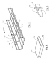
- a section 1a intended to form a constituent element of a cable tray which can be of various nature (telephone cables, electric cables, computer network cables, optical fiber cables and various flexible conduits, etc.) is shown in perspective.
- This section consists of a lattice 2 of mechanically welded son together in a perpendicular pattern delimiting mesh of son.
- the section la is in the form of a gutter having a bottom 14 and side walls 15, 16.
- the trellis 2 has undergone an electro-galvanizing treatment, in order to avoid the problems due to electro-corrosion. chemical of the metal. It should be noted that other types of treatment against corrosion can be used such as hot-dip galvanizing after machining or the use of polymerized coatings.
- the use of stainless steel is made compulsory by the aggressiveness of the surrounding atmosphere. Furthermore, it is also possible to constitute lattices of son of composite materials (polyester reinforced with fiberglass or the like ). It will also be noted that the anti-corrosion treatment of the wires can take place before the welding of these wires to each other to form the trellis.
- the section of cable tray has a height of 60 mm and a width of 150 mm. Obviously, this type of trellis may have a different width and / or height depending on the use that it is desired to make of the cable tray formed by the assembly of such sections.
- the section la of cable tray is in the form of an asymmetrical module having two complementary ends each forming a coupling member in reversible position.
- a first coupling member is constituted by two metal splices 3.
- Each of these ribs 3 has a width very slightly less than the width of the meshes 8 of the trellis 2 which receives them.
- Each of the fishplates 3 is positioned in one of these meshes 8 so as not to protrude outside the side walls 15, 16 of the gutter.
- the proximal ends 4 of the fishplates 3 are each secured to the meshes 8 by two welding points 13. These welding points 13 make it possible to securely fasten the fishplates 3 to the wire mesh 2.
- the second coupling member is constituted by the two meshes 7 situated at the end of the section opposite to that at the level of which the meshes 8 are located.
- the method of manufacturing such a section consists in welding flat the fishplates 3 and the wires constituting the mesh network of the trellis 2, then in forming the gutter by bending or by folding this trellis provided with the fishplates 3.
- these fixing devices comprise, as shown in FIG. 2, welded plates 10 to one of the meshes 11 constituting the bottom of the gutter formed by the sections and are provided with openings 9.
- the welding of such devices makes it possible to reduce the number of accessories (such as jumpers, plates, toads) that must be used to secure the cable trays to a support.
- the distal end 5 of a fishplate 3 is shown in perspective.
- This distal end 5 is provided with a coupling lug 6 capable of cooperating with a wire 12 of a mesh 7 of another section of cable tray.
- Said coupling lug 6 is formed by cutting in said splint 3 a finger projecting from the contact surface of the splice 3, and capable of spreading to avoid the wire 12 during the operation assembly by embedding with another section of cable tray.
- the ribs 3 of a section constituting the first coupling member are introduced into the meshes 7 constituting the second coupling member of another section.
- the lugs 6 of the fishplates then move apart when they pass over the wires 12 of the meshes 7 and then return to their initial position once they have passed these wires, so as to snap onto them and thus form a reversible link between the two sections thus connected. It will be noted that, instead of such a coupling lug, it would also have been possible to provide the splint with a hooking lug, accommodating the second coupling member, when two sections are connected.
- the deformation of the splint 3 is such that it allows the reversibility of the positioning of the lug 6 on the wire 12.
- This lug 6 is directed towards the inside of the gutter formed by the lattice 2.
- the other splint 3 has a structure similar to that shown in FIG. 3 except that the lug 6 is formed so as to also be directed towards the inside of the trough of the trellis 2.
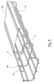
- connection by embedding of two sections 1a, 1b of cable tray according to the invention is carried out by introducing the coupling members constituted by fishplates 3 of a first section 1a into the coupling members formed by the meshes 7 of a second section 1b, in the direction displayed by the arrow.
- the sections 1a and 1b are shown partially, the section 1b not being provided with its first coupling member and the section 1a not being provided with its second coupling member.
- an annex connection device between two sections of cable tray according to the invention is in the form of a clip 17 which can be installed so as to connect the metal wires of two meshes belonging to the central part of two successive sections.
- the clip 17 has two elastic branches 18, 19.
- this clip 17 will be welded to the trellis at the end comprising the ribs 3.
- connection by embedding of a section 1a to another section 1b is carried out according to a simple and rapid operation requiring no conventional or specific tool.
- the assembly is carried out without the use of any bolts or other accessories and has excellent mechanical resistance.
- This assembly can be carried out in conditions of minimum bulk, for example when the cable tray must be formed along a wall.
- the cable tray made by assembling different sections has a harmonious aesthetic aspect, since the connection fishplates fit perfectly into the whole.
- the design of the fishplates 3 makes it possible to easily separate the various sections constituting a cable tray by performing reverse traction in the direction represented by the arrow.
- the fishplates having no external or internal roughness, the risk of cable tearing or deterioration of the materials located near the cable trays is very reduced. This makes it easier to fit a cover on the cable tray.
- a cable tray made in accordance with Figure 4 is shown partially.
- This cable path includes the two sections 1a and 1b shown in part and interconnected by the fishplates 3 of the section 1a.
- This cable tray has no external roughness, since the pins 6 of the fishplates 3 are directed towards the inside of the gutter formed by the cable tray. It can therefore easily accommodate a cover 20 consisting of a metal plate whose profile allows it to be fitted on the sections 1a and 1b. For the purposes of the description, this cover 20 is shown in part.
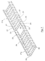
- two sections 21a, 21b are shown in perspective on the point of being connected by reversible embedding.
- These cable tray sections consist of perforated sheets.
- the sections 21a and 21b are shown partially, the section 21b not being provided with its first coupling member.
- the first coupling member of the section 21a is constituted by two ribs 23 formed in a perforated sheet, and the proximal ends 24 of which are welded to the side walls 35, 36 of the part forming the gutter of the section 21a.
- the distal ends 25 of these ribs 23 are, for their part, provided with coupling pins 26 formed by stamping in the perforated sheet forming the ribs 23.
- Said coupling pins 6 come, in the rest position, projecting from relative to the contact surface of the ribs 23. Their slope allows the slight lateral displacement of the ribs during the assembly operation with the section of cable tray 21B. The lateral play of the splint inside the rolled edge is made possible by the difference between the thickness of the splint and the internal width of the rolled edge.
- the ribs 23 of a section of cables constituting the first coupling member are embedded in the perforations 27 of another section constituting the second coupling member.
- the possible deformation of the ribs 23 is such that it allows the reversibility of the positioning of the pins 26 in the perforations 27.
Abstract
Description
La présente invention concerne la réalisation de structures en forme de gouttière permettant de supporter et de guider des câbles tels que, par exemple, des câbles électriques, des câbles téléphoniques, des câbles de fibres optiques, des câbles de réseau informatique ou toutes canalisations souples similaires. Ces structures sont désignées sous le terme de chemins de câbles et sont réalisées par l'assemblage de différents tronçons possédant une longueur et une largeur variables en fonction du nombre de câbles devant être disposés à l'intérieur de la gouttière qu'ils forment et de la longueur du chemin à parcourir.The present invention relates to the production of gutter-shaped structures for supporting and guiding cables such as, for example, electric cables, telephone cables, fiber optic cables, computer network cables or any similar flexible pipes. . These structures are designated by the term of cable trays and are produced by the assembly of different sections having a variable length and width depending on the number of cables to be laid inside the gutter they form and of the length of the path to travel.
Les tronçons constituant ces chemins de câbles sont classiquement constitués de structures en tôle perforée afin de les alléger ou par des treillis de fils d'acier mécano-soudés. Afin de résister à la corrosion, ces structures métalliques subissent généralement un traitement de surface de facture classique tel qu'un revêtement de peinture, un zingage ou une galvanisation à chaud. L'utilisation de l'acier inoxydable est parfois nécessaire pour combattre les atmosphères les plus agressives. Ces tronçons peuvent également être constitués de matériaux composites tels que le polyester armé.The sections constituting these cable trays are conventionally made up of perforated sheet structures in order to lighten them or by lattices of mechanically welded steel wires. In order to resist corrosion, these metallic structures generally undergo a surface treatment of conventional invoice such as a coating of paint, zinc plating or hot galvanization. The use of stainless steel is sometimes necessary to combat the most aggressive atmospheres. These sections can also be made of composite materials such as reinforced polyester.
Les tronçons de chemin de câbles réalisés à partir de fils de chaînes et de trames organisés en treillis sont généralement formés par soudure à plat des fils entre eux. Cette soudure est réalisée dans des calibres possédant un dimensionnement variable en fonction de la taille du tronçon que l'on souhaite obtenir. Une fois cette opération de soudure effectuée, le treillis est déformé par pliage ou par cambrage, de façon à prendre la forme d'une gouttière.The sections of cable tray made from warp and weft wires organized in lattices are generally formed by flat welding of the wires together. This welding is carried out in gauges having a variable dimensioning as a function of the size of the section which it is desired to obtain. Once this welding operation has been carried out, the lattice is deformed by folding or bending, so as to take the form of a gutter.
Un chemin de câbles complet est réalisé par l'assemblage d'un nombre déterminé de ces tronçons, en fonction de la longueur du chemin à parcourir par les câbles.A complete cable tray is produced by assembling a determined number of these sections, as a function of the length of the path to be covered by the cables.
Le principal problème posé par l'assemblage des tronçons de chemin de câbles de l'état de la technique est constitué par les différentes opérations et les différents systèmes utilisés pour pratiquer la jonction entre les différents tronçons. Une des plus anciennes méthodes utilisée pour assembler les tronçons de chemin de câbles entre eux consiste à utiliser des pièces rapportées se présentant sous la forme d'éclisses et à boulonner celles-ci entre deux tronçons de chemins de câbles consécutifs. La fixation des éclisses grâce à des boulons nécessite que celles-ci soient perforées de façon à pouvoir y introduire une vis, celle-ci étant ensuite bloquée par un écrou entre deux fils de trame d'extrémité par l'intermédiaire d'un cavalier. Cette solution ancienne présente divers inconvénients au rang desquels on compte la cherté en main d'oeuvre et en matériau.The main problem posed by the assembly of the cable tray sections of the prior art consists of the different operations and the different systems used to make the junction between the different sections. One of the oldest methods used to assemble the sections of cable tray together is to use inserts which are located under the form of splices and to bolt them between two sections of consecutive cable trays. The fixing of the fishplates by means of bolts requires that they be perforated so as to be able to introduce a screw therein, the latter then being blocked by a nut between two end weft threads by means of a jumper. This old solution has various drawbacks, including the high cost of labor and material.
On connaît également le document de brevet n° FR 2208219 qui concerne un dispositif d'assemblage de tronçons de chemins de câbles constitués par des treillis de fils soudés, caractérisé par le fait qu'il comporte latéralement au moins deux éclisses rigides dans leur partie centrale et élastiques dans leur partie d'extrémité, lesdites éclisses étant placées entre deux éléments longitudinaux de deux tronçons de chemin de câbles et étant maintenues en place grâce à leurs extrémités qui viennent chacune s'engager sur un fil transversal de chacun des deux tronçons de chemin de câble.Also known is patent document No. FR 2208219 which relates to a device for assembling sections of cable trays formed by lattices of welded wires, characterized in that it laterally comprises at least two rigid ribs in their central part. and elastic in their end part, said ribs being placed between two longitudinal elements of two sections of cable tray and being held in place by virtue of their ends which each come to engage on a transverse wire of each of the two sections of path of cable.
Ce dispositif présente l'inconvénient majeur de nécessiter un outil spécial pour la mise en place des éclisses élastiques en question. Cet outil, qui possède la faculté de tendre et de tirer en même temps les extrémités élastiques de l'éclisse afin que celle-ci vienne se bloquer sur certains fils des mailles du treillis constituant le tronçon de chemin de câbles, nécessite un débattement important pour être manoeuvré. Or, les chemins de câbles sont souvent disposés le long des murs selon un positionnement ne permettant pas un tel débattement. De plus, un autre inconvénient présenté par le dispositif d'assemblage de tronçons de chemin de câbles selon ce document de brevet français consiste dans le fait qu'une fois les éclisses placées entre les tronçons, il est très difficile de les en ôter. Ainsi, si le dispositif divulgué favorise l'assemblage des tronçons de chemin de câbles, il défavorise leur désassemblage et ainsi leur réutilisation.This device has the major drawback of requiring a special tool for the installation of the elastic ribs in question. This tool, which has the ability to tension and pull at the same time the elastic ends of the splint so that it comes to hang on certain wires of the mesh of the trellis constituting the section of cable tray, requires a large clearance for to be manipulated. However, the cable trays are often arranged along the walls in a positioning which does not allow such a clearance. In addition, another drawback presented by the device for assembling cable tray sections according to this French patent document consists in the fact that once the ribs are placed between the sections, it is very difficult to remove them. Thus, if the disclosed device promotes the assembly of the sections of cable tray, it disadvantages their disassembly and thus their reuse.
En outre, les éclisses utilisées font intervenir plusieurs angles vifs qui contribuent à augmenter les risques de blessure à l'intérieur de la gouttière vis à vis des câbles qui y sont disposés et à l'extérieur de la gouttière vis à vis des ouvriers montant ces chemins de câbles ou des murs situés à proximité.In addition, the fishplates used involve several sharp angles which contribute to increasing the risk of injury inside the gutter with respect to the cables arranged therein and outside the gutter with respect to workers mounting these cable trays or walls located nearby.
Par ailleurs, le dispositif d'assemblage décrit dans ce brevet n'est pas adapté pour être utilisé avec les tronçons de chemins de câbles constitués par des tôles perforées.Furthermore, the assembly device described in this patent is not suitable for use with the sections of cable trays formed by perforated sheets.
En ce qui concerne les chemins de câbles en tôle perforée, différents systèmes d'assemblage ont été envisagés. Ainsi, on connaît des dispositifs d'assemblage constitués par des plaques épousant les bords des gouttières formant le chemin de câbles et présentant des perforations aptes à rentrer en regard avec les perforations des tronçons. Ces pièces peuvent être disposées à la jonction entre les tronçons et solidarisées à ceux-ci grâce à des clips ou des vis permettant de plaquer fermement les pièces d'assemblage contre les tronçons. Cependant, à l'image des éclisses précédemment décrites, ces vis présentent l'inconvénient de nécessiter des outils particuliers pour être mises en place et les clips présentent l'inconvénient d'être difficiles à désolidariser des tronçons une fois qu'ils ont été placés sur ceux-ci. De plus, les clips ou les vis décrits dépassent largement à l'extérieur des tronçons, ce qui augmente de façon importante leur encombrement et constitue des sources d'arrachement potentielles vis-à-vis des différentes structures se trouvant à proximité des chemins de câbles.With regard to the cable tray made of perforated sheet metal, various assembly systems have been envisaged. Thus, assembly devices are known which consist of plates matching the edges of the gutters forming the cable tray and having perforations capable of coming into contact with the perforations of the sections. These parts can be arranged at the junction between the sections and secured to them by means of clips or screws making it possible to firmly press the assembly parts against the sections. However, like the splices previously described, these screws have the drawback of requiring special tools to be put in place and the clips have the drawback of being difficult to separate sections once they have been placed. on these. In addition, the clips or screws described protrude well outside the sections, which significantly increases their size and are potential sources of pullout vis-à-vis the various structures located near the cable trays .
L'objectif de la présente invention est de fournir un tronçon de chemin de câbles pouvant être relié à un autre tronçon identique sans l'intervention d'une pièce rapportée.The objective of the present invention is to provide a section of cable tray which can be connected to another identical section without the intervention of an insert.
Un autre objectif de l'invention est de fournir un tel tronçon ne présentant pas les inconvénients des dispositifs d'assemblage de tronçons de chemins de câbles de l'état de la technique.Another objective of the invention is to provide such a section which does not have the drawbacks of prior art devices for assembling sections of cable trays.
En particulier, l'invention a pour objectif de fournir un tel tronçon permettant de monter un chemin de câbles avec un gain de temps substantiel.In particular, the invention aims to provide such a section for mounting a cable tray with a substantial time saving.
Un autre objectif de l'invention est également de faciliter le démontage de tels chemins de câbles.Another object of the invention is also to facilitate the dismantling of such cable trays.
Un autre objectif de l'invention est de fournir un tronçon de chemin de câbles dont l'assemblage permet de supprimer tout boulon ou accessoire ainsi que tout outil standard ou spécial nécessaire au montage de tels boulons ou accessoires.Another objective of the invention is to provide a section of cable tray, the assembly of which makes it possible to remove any bolt or accessory as well as any standard or special tool necessary for mounting such bolts or accessories.
Un autre objectif complémentaire de l'invention est également de fournir un tronçon de chemin de câbles présentant un aspect esthétique harmonieux.Another complementary objective of the invention is also to provide a section of cable tray having a harmonious aesthetic appearance.
Enfin, un autre objectif de l'invention est de proposer un tronçon de chemin de câbles présentant des caractéristiques facilitant le montage sur celui-ci de couvercles.Finally, another objective of the invention is to propose a section of cable tray having characteristics facilitating the mounting thereon of covers.
Ces différents objectifs ainsi que d'autres qui apparaîtront par la suite sont atteints grâce à un tronçon de chemin de câbles se présentant sous la forme d'une gouttière caractérisé en ce qu'il est constitué par un module asymétrique présentant deux extrémités complémentaires formant chacune un organe d'accouplement par encastrement réversible, un premier organe d'accouplement étant constitué par au moins une éclisse dont l'extrémité proximale est soudée à ladite gouttière et dont l'extrémité distale est munie d'un ergot d'accouplement, le second organe d'accouplement étant formé dans au moins une partie de ladite gouttière et étant susceptible d'accueillir ledit ergot d'accouplement.These various objectives as well as others which will appear subsequently are achieved by virtue of a section of cable tray which is in the form of a gutter, characterized in that it is constituted by an asymmetrical module having two complementary ends each forming a reversible embedding coupling member, a first coupling member consisting of at least one fishplate whose proximal end is welded to said groove and whose distal end is provided with a coupling lug, the second coupling member being formed in at least part of said gutter and being capable of receiving said coupling pin.
En dépit des nombreux avantages qu'elle présente, la solution consistant à souder directement l'éclisse sur la structure formant la gouttière n'avait jusqu'alors jamais été utilisée, probablement en raison de l'existence d'un préjugé de l'homme du métier en faveur de systèmes à éclisses indépendantes. De plus, il n'avait jusqu'ici jamais été envisagé d'utiliser des structures de chemin de câbles en fils soudés présentant à la fois un organe mâle et un organe femelle permettant de joindre ces structures entre elles par encastrement.Despite the many advantages that it has, the solution consisting in directly welding the splint on the structure forming the gutter had never been used until then, probably due to the existence of a prejudice of the man of the trade in favor of independent fishplate systems. In addition, it had hitherto never been envisaged to use cable tray structures in welded wires having both a male and a female member making it possible to join these structures together by embedding.
Selon une première variante, ledit tronçon comprend au moins deux éclisses dont les extrémités proximales sont soudées aux parois latérales de ladite gouttière, symétriquement par rapport à l'axe longitudinal de celle-ci, de façon à se faire face.According to a first variant, said section comprises at least two fishplates whose proximal ends are welded to the side walls of said gutter, symmetrically with respect to the longitudinal axis of the latter, so as to face each other.
Selon une autre variante, ledit tronçon comprend au moins deux éclisses, l'une desdites éclisses étant soudée à l'extrémité d'une des parois latérales de ladite gouttière et l'autre éclisse étant soudée à l'extrémité opposée de l'autre paroi latérale de ladite gouttière.According to another variant, said section comprises at least two fishplates, one of said fishplates being welded to the end of one of the side walls of said gutter and the other fishplate being welded to the opposite end of the other wall lateral of said gutter.
En effet, bien que l'on puisse envisager de n'utiliser qu'une seule éclisse, par exemple placée dans la zone centrale de la partie inférieure de la gouttière, l'utilisation de deux éclisses reliant les parois latérales de cette gouttière permet d'obtenir un assemblage davantage sécurisé des deux tronçons qu'elles relient. Pour des raisons de stockage, la première variante consistant à souder les éclisses sur les parois latérales de la gouttière de façon à se faire face est la solution préférée car elle permet de faciliter le stockage et le montage des tronçons de chemins de câbles.Indeed, although we can consider using only one splint, for example placed in the central area of the lower part of the gutter, the use of two fishplates connecting the side walls of this gutter makes it possible to obtain a more secure assembly of the two sections that they connect. For storage reasons, the first variant consisting in welding the ribs on the side walls of the gutter so as to face each other is the preferred solution because it makes it easier to store and assemble the sections of cable trays.
Préférentiellement, ledit ergot d'accouplement est constitué par un doigt venant en saillie par rapport à la surface de ladite éclisse et formé par découpage ou par emboutissage dans celle-ci, le matériau constituant ladite éclisse présentant une élasticité suffisante pour permettre à l'ergot de venir s'encliqueter sur le second organe d'accouplement, lors de l'opération d'assemblage avec un autre tronçon de chemin de câbles.Preferably, said coupling lug is constituted by a finger projecting from the surface of said splint and formed by cutting or stamping therein, the material constituting said splice having sufficient elasticity to allow the lug to snap onto the second coupling member, during the assembly operation with another section of cable tray.
Selon ce mode de réalisation, l'ergot de chaque éclisse peut venir s'encliqueter sur le second organe d'accouplement d'un autre tronçon de chemin de câbles et ainsi réaliser une liaison sécurisée entre les tronçons, mais peut aussi échapper à ce second organe d'accouplement qui le retient et faciliter par là le désaccouplé des deux tronçons de chemin de câbles ainsi reliés. Cet aspect réversible de l'assemblage constitue un avantage important de l'invention par rapport aux dispositifs existant de l'état actuel de la technique. En effet ces dispositifs existant nécessitent pour être démontés, du temps et parfois un équipement spécialisé.According to this embodiment, the lug of each splint can snap onto the second coupling member of another section of cable tray and thus achieve a secure connection between the sections, but can also escape this second coupling member which retains it and thereby facilitates the uncoupling of the two cable tray sections thus connected. This reversible aspect of the assembly constitutes an important advantage of the invention compared to the existing devices of the current state of the art. Indeed these existing devices require to be dismantled, time and sometimes specialized equipment.
La réversibilité de l'assemblage des tronçons selon l'invention est rendue possible, dans le cadre de cet aspect préférentiel de l'invention, grâce au découpage de l'ergot dans les extrémités distales mêmes des éclisses. En effet, le matériau constituant les éclisses présente un élasticité suffisante pour permettre aux ergots d'être rappelés en position de repos, lorsqu'ils sont séparés du second organe d'accouplement.The reversibility of the assembly of the sections according to the invention is made possible, in the context of this preferred aspect of the invention, thanks to the cutting of the lug in the very distal ends of the fishplates. Indeed, the material constituting the ribs has sufficient elasticity to allow the lugs to be returned to the rest position, when they are separated from the second coupling member.
Selon une variante, ledit tronçon de chemin de câbles est constitué par un treillis de fils métalliques soudés entre eux, ledit second organe d'accouplement étant constitué par au moins une maille dudit treillis.According to a variant, said section of cable tray is constituted by a lattice of metallic wires welded together, said second coupling member being constituted by at least one mesh of said lattice.
Préférentiellement, la largeur de ladite maille formant ledit second organe d'accouplement est très légèrement supérieure à celle de ladite éclisse constituant ledit premier organe d'accouplement, de façon à permettre un guidage à faible jeu de ladite éclisse dans ladite maille.Preferably, the width of said mesh forming said second coupling member is very slightly greater than that of said splint constituting said first coupling member, so as to allow a low clearance guidance of said splice in said mesh.
Egalement préférentiellement, la longueur de ladite maille formant ledit second organe d'accouplement est d'une longueur telle que la liaison entre le premier organe d'accouplement constitué par une éclisse dudit tronçon et le second organe d'accouplement constitué par une maille d'un autre tronçon est une liaison hyperstatique en position d'encastrement.Also preferably, the length of said mesh forming said second coupling member is of a length such that the connection between the first coupling member constituted by a fishplate of said section and the second coupling member constituted by a mesh another section is a hyperstatic connection in the installation position.
Selon une autre variante, ledit tronçon est constitué par une tôle perforée, ledit second organe d'accouplement étant constitué par au moins une perforation de ladite tôle.According to another variant, said section is constituted by a perforated sheet, said second coupling member being constituted by at least one perforation of said sheet.
Selon un autre aspect intéressant de l'invention, lesdites éclisses ne présentent aucune aspérité dépassant à l'extérieur dudit tronçon afin de pouvoir accueillir un couvercle. Les couvercles utilisés peuvent être de différente nature et présenteront avantageusement un aspect esthétique harmonieux avec l'aspect des tronçons eux-mêmes. Ils pourront par exemple être constitués de tôle pleine et venir s'encliqueter sur la partie supérieure des tronçons et auront préférentiellement la même longueur que ceux-ci.According to another interesting aspect of the invention, said fishplates have no roughness protruding outside of said section in order to accommodate a cover. The covers used can be of different nature and will advantageously have an aesthetic appearance harmonious with the appearance of the sections themselves. They may for example be made of solid sheet metal and snap onto the upper part of the sections and preferably have the same length as these.
Selon un autre aspect avantageux de l'invention, le tronçon de chemin de câbles comprend au moins une éclisse soudée par son extrémité proximale à la partie centrale dudit tronçon formant le fond de ladite gouttière.According to another advantageous aspect of the invention, the section of cable tray comprises at least one splice welded by its proximal end to the central part of said section forming the bottom of said gutter.
De cette manière, outre les deux éclisses situées sur les parties latérales de la gouttière constituant le chemin de câbles formé par l'assemblage des différents tronçons, une ou plusieurs éclissent centrales viennent sécuriser l'assemblage des tronçons entre eux. Plus la largeur du tronçon sera grande, plus le nombre d'éclisses centrales sera important.In this way, in addition to the two fishplates located on the lateral parts of the gutter constituting the cable tray formed by the assembly of the different sections, one or more central fishplates secure the assembly of the sections between them. The greater the width of the section, the greater the number of central fishplates.
L'invention concerne également un procédé de fabrication de tels tronçons de chemin de câbles caractérisé en ce qu'il comprend les étapes consistant :
- à souder à plat lesdites éclisses sur la structure métallique destiné à constituer ladite gouttière ;
- à former ladite gouttière par pliage, par profilage ou par cambrage de ladite structure munie d'une ou de plusieurs éclisses ainsi réalisée.
- flat welding said ribs on the metal structure intended to constitute said gutter;
- forming said gutter by folding, by profiling or by bending said structure provided with one or more fishplates thus produced.
Les tronçons pourront aussi être fabriqués selon un autre procédé selon l'invention consistant :
- à former ladite gouttière par pliage ou par cambrage de la structure métallique eux;
- à souder lesdites éclisses sur ladite gouttière ainsi formée.
- forming said gutter by folding or bending the metal structure them;
- welding said ribs onto said gutter thus formed.
Le procédé consistant à souder à plat les éclisses est toutefois économiquement préférable à ce dernier procédé.The method of flat welding the ribs is however economically preferable to the latter method.
Préférentiellement, l'opération de soudage de ladite ou desdites éclisses est réalisée par soudure électrique par points.Preferably, the welding operation of said one or more fishplates is carried out by electric spot welding.
L'invention ainsi que les différents avantages qu'elle présente seront plus facilement compris en référence à la description qui va suivre de deux exemples de réalisation d'un tronçon de chemin de câbles, en référence aux dessins dans lesquels
- la figure 1 représente une vue en perspective d'un premier mode de réalisation d'un tronçon de chemin de câbles selon l'invention ;
- la figure 2 représente une vue en perspective d'un dispositif de fixation annexe pouvant être utilisé pour la fixation d'un tronçon selon la figure 1 à la structure porteuse (console, mur, plafond) par l'intermédiaire de boulonnerie standard ;
- la figure 3 représente l'extrémité distale d'une des deux éclisses du tronçon de chemin de câbles de la figure 1, lorsque celle-ci est ajustée à un autre tronçon du même type ;
- la figure 4 représente une vue en perspective de la liaison par encastrement réversible entre deux tronçons selon la figure 1 ;
- la figure 5 représente un dispositif de liaison annexe pouvant être utilisé, de façon complémentaire, pour relier deux tronçons de chemins de câbles selon la figure 1 ;
- la figure 6 représente une vue en perspective de la liaison par encastrement réversible de deux tronçons selon la figure 4 munis d'un couvercle de protection ;
- la figure 7 représente deux tronçons de chemins de câbles réalisés selon un second mode de réalisation et sur le point d'être reliés entre eux par encastrement réversible.
- FIG. 1 represents a perspective view of a first embodiment of a section of cable tray according to the invention;
- 2 shows a perspective view of an annex fixing device which can be used for fixing a section according to Figure 1 to the supporting structure (console, wall, ceiling) by means of standard bolts;
- Figure 3 shows the distal end of one of the two fishplates of the cable tray section of Figure 1, when the latter is adjusted to another section of the same type;
- 4 shows a perspective view of the connection by reversible embedding between two sections according to Figure 1;
- FIG. 5 represents an annex connection device which can be used, in a complementary manner, to connect two sections of cable trays according to FIG. 1;
- 6 shows a perspective view of the connection by reversible embedding of two sections according to Figure 4 provided with a protective cover;
- FIG. 7 represents two sections of cable trays produced according to a second embodiment and about to be connected together by reversible embedding.
Selon la figure 1, un tronçon la destiné à former un élément constitutif d'un chemin de câbles pouvant être de nature diverse (câbles téléphoniques, câbles électriques, câbles de réseau informatique, câbles de fibres optiques et conduits souples divers...)est représenté en perspective. Ce tronçon est constitué d'un treillis 2 de fils mécano-soudés entre eux selon un motif perpendiculaire délimitant des mailles de fils. Le tronçon la se présente sous la forme d'une gouttière présentant un fond 14 et des parois latérales 15, 16. Le treillis 2 a subi un traitement d'électro-zingage, en vue d'éviter les problèmes dus à la corrosion électro-chimique du métal. On notera que d'autres types de traitement contre la corrosion peuvent être utilisés tels que la galvanisation à chaud après usinage ou l'emploi de revêtements polymérisés. Dans certains cas, l'utilisation de l'acier inoxydable est rendue obligatoire par l'agressivité de l'ambiance environnante. Par ailleurs, il est également envisageable de constituer des treillis de fils de matériaux composites (polyester armé de fibre de verre ou autres...). On notera également que le traitement anti-corrosion des fils peut avoir lieu avant le soudage de ces fils entre eux pour former le treillis. Le tronçon la de chemin de câbles présente une hauteur de 60 mm et une largeur de 150 mm. Bien évidemment, ce type de treillis peut présenter une largeur et/ou une hauteur différentes suivant l'utilisation que l'on désire faire du chemin de câbles formé par l'assemblage de tels tronçons.According to FIG. 1, a
Selon l'invention, le tronçon la de chemin de câbles se présente sous la forme d'un module asymétrique présentant deux extrémités complémentaires formant chacune un organe d'accouplement à position réversible. Un premier organe d'accouplement est constitué par deux éclisses 3 métalliques. Chacune de ces éclisses 3 possède une largeur très légèrement inférieure à la largeur des mailles 8 du treillis 2 qui les accueille. Chacune des éclisses 3 est positionnée dans une de ces mailles 8 de façon à ne pas dépasser à l'extérieur des parois latérales 15, 16 de la gouttière. Les extrémités proximales 4 des éclisses 3 sont chacune solidarisées aux mailles 8 par deux points de soudure 13. Ces points de soudure 13 permettent de solidariser de façon sécurisée les éclisses 3 au treillis métallique 2.According to the invention, the section la of cable tray is in the form of an asymmetrical module having two complementary ends each forming a coupling member in reversible position. A first coupling member is constituted by two metal splices 3. Each of these
Le second organe d'accouplement est constitué par les deux mailles 7 situées à l'extrémité du tronçon opposée à celle au niveau de laquelle se trouvent les mailles 8.The second coupling member is constituted by the two
Selon l'invention, le procédé de fabrication d'un tel tronçon consiste à souder à plat les éclisses 3 et les fils constituant le réseau de mailles du treillis 2, puis à former la gouttière par cambrage ou par pliage de ce treillis muni des éclisses 3.According to the invention, the method of manufacturing such a section consists in welding flat the
Afin de faciliter la fixation des chemins de câbles réalisés à partir de tels tronçons à une structure porteuse, ceux-ci peuvent être munis, dans leur partie centrale d'un ou plusieurs dispositifs de fixation. Avantageusement, ces dispositifs de fixation comprennent, comme représenté à la figure 2, des plaques soudées 10 à une des mailles 11 constituant le fond de la gouttière que forme les tronçons et sont munis d'ouvertures 9. Le soudage de tels dispositifs permet de diminuer le nombre d'accessoires (tels que cavaliers, plaques, crapauds) qui doivent être utilisés pour solidariser les chemins de câbles à un support.In order to facilitate the fixing of the cable trays produced from such sections to a support structure, these can be provided, in their central part with one or more fixing devices. Advantageously, these fixing devices comprise, as shown in FIG. 2, welded
Selon la figure 3, l'extrémité distale 5 d'une éclisse 3 est représentée en perspective. Cette extrémité distale 5 est munie d'un ergot d'accouplement 6 apte à coopérer avec un fil 12 d'une maille 7 d'un autre tronçon de chemin de câbles. Ledit ergot d'accouplement 6 est formé par découpage dans ladite éclisse 3 d'un doigt venant en saillie par rapport à la surface de contact de l'éclisse 3, et susceptible de s'écarter pour éviter le fil 12 lors de l'opération d'assemblage par encastrement avec un autre tronçon de chemin de câble. Ainsi, lors de la constitution d'un chemin de câbles, les éclisses 3 d'un tronçon constituant le premier organe d'accouplement sont introduites dans les mailles 7 constituant le second organe d'accouplement d'un autre tronçon. Les ergots 6 des éclisses s'écartent alors au moment où ils passent sur les fils 12 des mailles 7 puis reprennent leur position initiale une fois qu'ils ont dépassé ces fils, de façon à s'enclencher sur ceux-ci et ainsi à former une liaison réversible entre les deux tronçons ainsi reliés. On notera, qu'à la place d'un tel ergot d'accouplement, il aurait été également possible de munir l'éclisse d'une patte d'accrochage, accueillant le second organe d'accouplement, lors du raccordement de deux tronçons.According to Figure 3, the
La déformation de l'éclisse 3 est telle qu'elle permet la réversibilité du positionnement de l'ergot 6 sur le fil 12. Cet ergot 6 est dirigé vers l'intérieur de la gouttière formée par le treillis 2. L'autre éclisse 3 présente une structure similaire à celle représentée à la figure 3 sauf en ce que l'ergot 6 est formé de façon à être dirigé également vers l'intérieur de la gouttière du treillis 2.The deformation of the
Selon la figure 4, la liaison par encastrement de deux tronçons 1a, 1b de chemin de câbles selon l'invention est réalisée en introduisant les organes d'accouplement constitués par des éclisses 3 d'un premier tronçon 1a dans les organes d'accouplement constitués par les mailles 7 d'un second tronçon 1b, dans le sens visualisé par la flèche. Pour les commodités de la description, les tronçons 1a et 1b sont représentés partiellement, le tronçon 1b n'étant pas pourvu de son premier organe d'accouplement et le tronçon la n'étant pas pourvu de son second organe d'accouplement.According to FIG. 4, the connection by embedding of two
Cette introduction permet de positionner les ergots 6 des éclisses 3 sur les fils 12 des mailles 7. Ces éclisses se trouvent ainsi bloquées dans ces mailles 7 dont la longueur et la largeur sont conçues pour coopérer avec les éclisses 3 de façon à former une liaison hyperstatique entre les tronçons 1a et 1b.This introduction makes it possible to position the
On notera que pour des tronçons présentant une largeur plus importante que celle représentée aux figures 1 et 3, on pourra également munir ces tronçons d'une troisième éclisse positionnée dans la partie centrale de la zone formant le fond de la gouttière. On pourra également utiliser des dispositifs annexes permettant de relier les tronçons par leurs parties centrales, tels que celui représenté à la figure 5. Selon la figure 5, un dispositif de liaison annexe entre deux tronçons de chemin de câbles selon l'invention, se présente sous la forme d'un clip 17 qui peut être installé de façon à relier les fils métalliques de deux mailles appartenant à la partie centrale de deux tronçons successifs. A cet effet, le clip 17 présentent deux branches élastiques 18,19.Préférentiellement, ce clip 17 sera soudé sur le treillis à l'extrémité comportant les éclisses 3.It will be noted that for sections having a greater width than that shown in FIGS. 1 and 3, these sections may also be provided with a third splint positioned in the central part of the zone forming the bottom of the gutter. It is also possible to use additional devices making it possible to connect the sections by their central parts, such as that shown in Figure 5. According to Figure 5, an annex connection device between two sections of cable tray according to the invention, is in the form of a
Selon la figure 4, le raccordement par encastrement d'un tronçon 1a à un autre tronçon 1b est effectué selon une opération simple et rapide ne nécessitant aucun outil classique ou spécifique. Le montage est effectué sans utilisation aucune de boulons ou d'autres accessoires et présente une excellente résistance mécanique. Cet assemblage peut être effectué dans des conditions d'encombrement minimales, par exemple lorsque le chemin de câbles doit être formé le long d'un mur. Le chemin de câbles réalisé par l'assemblage de différents tronçons présente un aspect esthétique harmonieux, puisque les éclisses de raccordement s'intègrent parfaitement à l'ensemble.According to FIG. 4, the connection by embedding of a
Par ailleurs, la conception des éclisses 3 permet de désolidariser facilement les différents tronçons constituant un chemin de câbles en effectuant une traction inverse au sens représenté par la flèche.Furthermore, the design of the
De plus les éclisses ne présentant aucune aspérité extérieure ou intérieure, les risques d'arrachement de câbles ou de détérioration des matériaux se trouvant à proximité des chemins de câbles est très réduit. L'adaptation d'un couvercle sur le chemin de câbles en est ainsi facilitée.In addition, the fishplates having no external or internal roughness, the risk of cable tearing or deterioration of the materials located near the cable trays is very reduced. This makes it easier to fit a cover on the cable tray.
Selon la figure 6, un chemin de câbles réalisé conformément à la figure 4 est représenté partiellement. Ce chemin de câble inclut les deux tronçons 1a et 1b représentés en partie et reliés entre eux grâce aux éclisses 3 du tronçon 1a. Ce chemin de câbles ne présente aucune aspérité extérieure, puisque les ergots 6 des éclisses 3 sont dirigés vers l'intérieur de la gouttière que forme le chemin de câbles. Il peut donc aisément accueillir un couvercle 20 constitué par une plaque métallique dont le profil lui permet de venir s'encastrer sur les tronçons 1a et 1b. Pour les besoins de la description, ce couvercle 20 est représenté en partie.According to Figure 6, a cable tray made in accordance with Figure 4 is shown partially. This cable path includes the two
Selon la figure 7, deux tronçons 21a, 21b sont représentés en perspective sur le point d'être reliés par encastrement réversible. Ces tronçons de chemin de câbles sont constitués de tôles perforées. Pour les commodités de la description, les tronçons 21a et 21b sont représentés partiellement, le tronçon 21b n'étant pas pourvu de son premier organe d'accouplement. Le premier organe d'accouplement du tronçon 21a est constitué par deux éclisses 23 formées dans une tôle perforée, et dont les extrémités proximales 24 sont soudées aux parois latérales 35, 36 de la partie formant gouttière du tronçon 21a. Les extrémités distales 25 de ces éclisses 23 sont, quant à elles, munies d'ergots d'accouplement 26 formés par emboutissage dans la tôle perforée formant les éclisses 23. Lesdits ergots d'accouplement 6 viennent, en position de repos, en saillie par rapport à la surface de contact des éclisses 23. Leur pente autorise le léger déplacement latéral des éclisses lors de l'opération d'assemblage avec le tronçon de chemin de câbles 21B. Le jeu latéral de l'éclisse à l'intérieur du bord roulé est rendu possible grâce à la différence entre l'épaisseur de l'éclisse et la largeur intérieure du bord roulé. Ainsi, lors de la constitution d'un chemin de câbles, les éclisses 23 d'un tronçon de câbles constituant le premier organe d'accouplement sont encastrées dans les perforations 27 d'un autre tronçon constituant le second organe d'accouplement.According to Figure 7, two
La déformation possible des éclisses 23 est telle qu'elle permet la réversibilité du positionnement des ergots 26 dans les perforations 27.The possible deformation of the
Les modes de réalisation décrits dans les exemples ne sont en aucun cas limitatifs de l'invention. En particulier, l'homme de métier pourra aisément imaginer d'utiliser un nombre d'éclisses supérieur à deux ou à trois, de munir l'extrémité distale des éclisses de déformations présentant un aspect différent ou encore d'adapter l'invention à des treillis possédant des mailles, ou à des plaques présentant des perforations, de formes différentes.The embodiments described in the examples are in no way limitative of the invention. In particular, a person skilled in the art can easily imagine using a number of fishplates greater than two or three, providing the distal end of the fishplates with deformations having a different appearance, or even adapting the invention to trellis having meshes, or to plates having perforations, of different shapes.
Claims (13)
Applications Claiming Priority (2)
| Application Number | Priority Date | Filing Date | Title |
|---|---|---|---|
| FR929206461A FR2691590B1 (en) | 1992-05-22 | 1992-05-22 | SELF-BUILDING CABLE PATH LINES AND METHOD OF MANUFACTURING SUCH LINES. |
| FR9206461 | 1992-05-22 |
Publications (2)
| Publication Number | Publication Date |
|---|---|
| EP0571307A1 true EP0571307A1 (en) | 1993-11-24 |
| EP0571307B1 EP0571307B1 (en) | 1996-09-04 |
Family
ID=9430219
Family Applications (1)
| Application Number | Title | Priority Date | Filing Date |
|---|---|---|---|
| EP93460020A Expired - Lifetime EP0571307B1 (en) | 1992-05-22 | 1993-05-21 | Self-assembly of cable duct pieces and method of manufacture |
Country Status (7)
| Country | Link |
|---|---|
| EP (1) | EP0571307B1 (en) |
| AT (1) | ATE142381T1 (en) |
| DE (1) | DE69304416T2 (en) |
| DK (1) | DK0571307T3 (en) |
| ES (1) | ES2093949T3 (en) |
| FR (1) | FR2691590B1 (en) |
| GR (1) | GR3021826T3 (en) |
Cited By (26)
| Publication number | Priority date | Publication date | Assignee | Title |
|---|---|---|---|---|
| EP0905843A2 (en) * | 1997-09-24 | 1999-03-31 | OBO Bettermann GmbH & Co. KG. | Screwless Fastening device for wire cable trays |
| US6019323A (en) * | 1996-04-25 | 2000-02-01 | Jette; Roger | Flexible cable management system |
| US6138961A (en) * | 1994-12-22 | 2000-10-31 | Metal Deploye S.A. | Wire cable tray |
| ES2156487A1 (en) * | 1997-07-02 | 2001-06-16 | Basor Electric S A | Cable splicing for cable holder trays |
| US6361000B1 (en) | 1996-04-25 | 2002-03-26 | Roger Jette | Flexible cable management system |
| FR2814602A1 (en) * | 2000-09-27 | 2002-03-29 | Tolmega | CABLE PATH WITH RETRACTABLE SLIDE, CABLE PATHS OBTAINED BY ASSEMBLING SUCH TRUNKS |
| US6460812B1 (en) | 1999-06-24 | 2002-10-08 | Roger Jette | Flexible cable support apparatus and method |
| FR2825528A1 (en) * | 2001-06-01 | 2002-12-06 | Bernard Hennequin | Assembly of cable trays from components fabricated in wire, uses tongue attached to end of cable tray to slide into sleeve at end of joining cable tray |
| US6637704B2 (en) | 1999-06-24 | 2003-10-28 | Roger Jette | Flexible cable support apparatus and method |
| US6709186B2 (en) | 2001-11-16 | 2004-03-23 | Adc Telecommunications, Inc. | Coupler for cable trough |
| US6715719B2 (en) | 2002-03-27 | 2004-04-06 | Adc Telecommunications, Inc. | Coupler for cable trough |
| US6926236B2 (en) | 2002-03-04 | 2005-08-09 | Roger Jette | Cable tray apparatus and method |
| EP1580857A1 (en) * | 2004-03-22 | 2005-09-28 | Legrand Electric Limited | Cable trunking and ducting |
| US7029195B2 (en) | 2002-03-27 | 2006-04-18 | Adc Telecommunications, Inc. | Coupler for cable trough |
| US7315680B1 (en) | 2006-06-21 | 2008-01-01 | Adc Telecommunications, Inc. | Cable routing devices with integrated couplers |
| US7463809B2 (en) | 2007-02-21 | 2008-12-09 | Adc Telecommunications, Inc. | Coupler for cable trough |
| US7481597B2 (en) | 2007-02-21 | 2009-01-27 | Adc Telecommunications, Inc. | Coupler for cable trough |
| US7493005B2 (en) | 2007-02-21 | 2009-02-17 | Adc Telecommunications, Inc. | Coupler for cable trough |
| US7504583B2 (en) | 2007-02-21 | 2009-03-17 | Adc Telecommunications, Inc. | Coupler for cable trough |
| US7584929B2 (en) | 2007-02-21 | 2009-09-08 | Adc Telecommunications, Inc. | Coupler for cable trough |
| GB2467443A (en) * | 2009-01-30 | 2010-08-04 | Pemsa Pequeno Material Electri | Cable tray bridge for joining trays or ducts |
| US7815152B2 (en) | 2007-02-21 | 2010-10-19 | Adc Telecommunications, Inc. | Coupler for cable trough |
| US7896295B2 (en) | 2007-02-21 | 2011-03-01 | Adc Telecommunications, Inc. | Coupler for cable trough |
| WO2013007855A1 (en) * | 2011-07-14 | 2013-01-17 | Valdinox, S.L. | Section of cable tray |
| US8450381B2 (en) | 2004-02-06 | 2013-05-28 | Velocys, Inc. | Microchannel compression reactor |
| EP2816687A1 (en) | 2013-06-20 | 2014-12-24 | Niedax France | Cable-tray section with transverse locking, cable tray comprising such sections and method for manufacturing same |
Families Citing this family (8)
| Publication number | Priority date | Publication date | Assignee | Title |
|---|---|---|---|---|
| FR2751723B1 (en) * | 1996-07-26 | 1998-09-11 | Metal Deploye Sa | ASSEMBLY SLIDE FOR CABLE PATH SECTIONS AND CABLE PATH SECTIONS |
| DE19946388B4 (en) * | 1998-07-11 | 2007-08-16 | Obo Bettermann Gmbh & Co. Kg | Mesh cable tray |
| DE19831145C1 (en) * | 1998-07-11 | 1999-11-11 | Bettermann Obo Gmbh & Co Kg | Wire mesh cable tray for cable run |
| DE19841643B4 (en) * | 1998-09-11 | 2007-04-12 | Obo Bettermann Gmbh & Co. Kg | Cable tray made of sheet metal |
| DE202004019942U1 (en) | 2004-12-24 | 2006-04-27 | Obo Bettermann Gmbh & Co. Kg | Cable support device |
| TR201105767A2 (en) * | 2011-06-13 | 2012-12-21 | Kiraç Metal Ürünleri̇ San. Ve Ti̇c. Ltd. Şti̇. | Easy plug-in cable tray with no connection tools. |
| ES2695452A1 (en) * | 2017-06-29 | 2019-01-04 | Unex Aparellaje Electrico Sl | Procedure for manufacturing a grid cable tray, and corresponding grid cable tray (Machine-translation by Google Translate, not legally binding) |
| ES1201060Y (en) | 2017-11-06 | 2018-09-19 | Pemsa Cable Man S A | UNION DEVICE FOR REJILLA PORTABLE TRAYS AND REJILLA PORTABLE TRAY TRAY |
Citations (3)
| Publication number | Priority date | Publication date | Assignee | Title |
|---|---|---|---|---|
| US3042351A (en) * | 1960-05-27 | 1962-07-03 | Bois Marvin A Du | Cable trays |
| US3161722A (en) * | 1963-02-13 | 1964-12-15 | Otis Elevator Co | Ready access wiring duct |
| FR2208219A1 (en) | 1972-11-27 | 1974-06-21 | Metal Deploye Sa |
-
1992
- 1992-05-22 FR FR929206461A patent/FR2691590B1/en not_active Expired - Fee Related
-
1993
- 1993-05-21 EP EP93460020A patent/EP0571307B1/en not_active Expired - Lifetime
- 1993-05-21 DE DE69304416T patent/DE69304416T2/en not_active Expired - Lifetime
- 1993-05-21 DK DK93460020.6T patent/DK0571307T3/da active
- 1993-05-21 ES ES93460020T patent/ES2093949T3/en not_active Expired - Lifetime
- 1993-05-21 AT AT93460020T patent/ATE142381T1/en active
-
1996
- 1996-11-28 GR GR960403217T patent/GR3021826T3/en unknown
Patent Citations (3)
| Publication number | Priority date | Publication date | Assignee | Title |
|---|---|---|---|---|
| US3042351A (en) * | 1960-05-27 | 1962-07-03 | Bois Marvin A Du | Cable trays |
| US3161722A (en) * | 1963-02-13 | 1964-12-15 | Otis Elevator Co | Ready access wiring duct |
| FR2208219A1 (en) | 1972-11-27 | 1974-06-21 | Metal Deploye Sa |
Cited By (46)
| Publication number | Priority date | Publication date | Assignee | Title |
|---|---|---|---|---|
| US6138961A (en) * | 1994-12-22 | 2000-10-31 | Metal Deploye S.A. | Wire cable tray |
| US6019323A (en) * | 1996-04-25 | 2000-02-01 | Jette; Roger | Flexible cable management system |
| US6361000B1 (en) | 1996-04-25 | 2002-03-26 | Roger Jette | Flexible cable management system |
| ES2156487A1 (en) * | 1997-07-02 | 2001-06-16 | Basor Electric S A | Cable splicing for cable holder trays |
| EP0905843A2 (en) * | 1997-09-24 | 1999-03-31 | OBO Bettermann GmbH & Co. KG. | Screwless Fastening device for wire cable trays |
| EP0905843A3 (en) * | 1997-09-24 | 2000-10-11 | OBO Bettermann GmbH & Co. KG. | Screwless Fastening device for wire cable trays |
| US6460812B1 (en) | 1999-06-24 | 2002-10-08 | Roger Jette | Flexible cable support apparatus and method |
| US6637704B2 (en) | 1999-06-24 | 2003-10-28 | Roger Jette | Flexible cable support apparatus and method |
| EP1193821A1 (en) * | 2000-09-27 | 2002-04-03 | Tolmega, S.A. | Section of cableway with retractable connector and cableway obtained by assembling two sections |
| FR2814602A1 (en) * | 2000-09-27 | 2002-03-29 | Tolmega | CABLE PATH WITH RETRACTABLE SLIDE, CABLE PATHS OBTAINED BY ASSEMBLING SUCH TRUNKS |
| FR2825528A1 (en) * | 2001-06-01 | 2002-12-06 | Bernard Hennequin | Assembly of cable trays from components fabricated in wire, uses tongue attached to end of cable tray to slide into sleeve at end of joining cable tray |
| US7175137B2 (en) | 2001-11-16 | 2007-02-13 | Adc Telecommunications, Inc. | Coupler for cable trough |
| US6709186B2 (en) | 2001-11-16 | 2004-03-23 | Adc Telecommunications, Inc. | Coupler for cable trough |
| US8444095B2 (en) | 2001-11-16 | 2013-05-21 | Adc Telecommunications, Inc. | Coupler for cable trough |
| US8186633B2 (en) | 2001-11-16 | 2012-05-29 | Adc Telecommunications, Inc. | Coupler for cable trough |
| US7360743B2 (en) | 2001-11-16 | 2008-04-22 | Adc Telecommunications, Inc. | Coupler for cable trough |
| US6926236B2 (en) | 2002-03-04 | 2005-08-09 | Roger Jette | Cable tray apparatus and method |
| US8365384B2 (en) | 2002-03-27 | 2013-02-05 | Adc Telecommunications, Inc. | Coupler for cable trough |
| US7029195B2 (en) | 2002-03-27 | 2006-04-18 | Adc Telecommunications, Inc. | Coupler for cable trough |
| US7093997B2 (en) | 2002-03-27 | 2006-08-22 | Adc Telecommunications, Inc. | Coupler for cable trough |
| US6715719B2 (en) | 2002-03-27 | 2004-04-06 | Adc Telecommunications, Inc. | Coupler for cable trough |
| US9104004B2 (en) | 2002-03-27 | 2015-08-11 | Adc Telecommunications, Inc. | Coupler for cable trough |
| US10114189B2 (en) | 2002-03-27 | 2018-10-30 | Commscope Technologies Llc | Coupler for cable trough |
| US7614817B2 (en) | 2002-03-27 | 2009-11-10 | Adc Telecommunications, Inc. | Coupler for cable trough |
| US8460411B2 (en) | 2004-02-06 | 2013-06-11 | Velocys, Inc. | Microchannel compression reactor |
| US8450381B2 (en) | 2004-02-06 | 2013-05-28 | Velocys, Inc. | Microchannel compression reactor |
| EP1580857A1 (en) * | 2004-03-22 | 2005-09-28 | Legrand Electric Limited | Cable trunking and ducting |
| US7315680B1 (en) | 2006-06-21 | 2008-01-01 | Adc Telecommunications, Inc. | Cable routing devices with integrated couplers |
| US8256723B2 (en) | 2006-06-21 | 2012-09-04 | Adc Telecommunications, Inc. | Cable routing devices with integrated couplers |
| US7922129B2 (en) | 2006-06-21 | 2011-04-12 | Adc Telecommunications, Inc. | Cable routing devices with integrated couplers |
| US7504583B2 (en) | 2007-02-21 | 2009-03-17 | Adc Telecommunications, Inc. | Coupler for cable trough |
| US7896295B2 (en) | 2007-02-21 | 2011-03-01 | Adc Telecommunications, Inc. | Coupler for cable trough |
| US7815152B2 (en) | 2007-02-21 | 2010-10-19 | Adc Telecommunications, Inc. | Coupler for cable trough |
| US7584929B2 (en) | 2007-02-21 | 2009-09-08 | Adc Telecommunications, Inc. | Coupler for cable trough |
| US7493005B2 (en) | 2007-02-21 | 2009-02-17 | Adc Telecommunications, Inc. | Coupler for cable trough |
| US7481597B2 (en) | 2007-02-21 | 2009-01-27 | Adc Telecommunications, Inc. | Coupler for cable trough |
| US7463809B2 (en) | 2007-02-21 | 2008-12-09 | Adc Telecommunications, Inc. | Coupler for cable trough |
| GB2467443A (en) * | 2009-01-30 | 2010-08-04 | Pemsa Pequeno Material Electri | Cable tray bridge for joining trays or ducts |
| WO2013007855A1 (en) * | 2011-07-14 | 2013-01-17 | Valdinox, S.L. | Section of cable tray |
| EP2733803A4 (en) * | 2011-07-14 | 2015-03-18 | Valdinox Sl | Section of cable tray |
| EP2733803B1 (en) | 2011-07-14 | 2016-03-09 | Valdinox, S.L. | Section of cable tray |
| EA024577B1 (en) * | 2011-07-14 | 2016-09-30 | Валдинокс, С.Л. | Section of cable tray |
| US9525277B2 (en) | 2011-07-14 | 2016-12-20 | Valdinox, S.L. | Section of cable tray |
| ES2396209A1 (en) * | 2011-07-14 | 2013-02-19 | Valdinox, S.L. | Section of cable tray |
| DE102013224380A1 (en) | 2013-06-20 | 2014-12-24 | Niedax France | Transversal snap-in cable duct section, cable duct with such sections and manufacturing process |
| EP2816687A1 (en) | 2013-06-20 | 2014-12-24 | Niedax France | Cable-tray section with transverse locking, cable tray comprising such sections and method for manufacturing same |
Also Published As
| Publication number | Publication date |
|---|---|
| FR2691590A1 (en) | 1993-11-26 |
| FR2691590B1 (en) | 1994-07-29 |
| DE69304416D1 (en) | 1996-10-10 |
| ATE142381T1 (en) | 1996-09-15 |
| DK0571307T3 (en) | 1997-02-24 |
| EP0571307B1 (en) | 1996-09-04 |
| GR3021826T3 (en) | 1997-02-28 |
| ES2093949T3 (en) | 1997-01-01 |
| DE69304416T2 (en) | 1997-04-03 |
Similar Documents
| Publication | Publication Date | Title |
|---|---|---|
| EP0571307B1 (en) | Self-assembly of cable duct pieces and method of manufacture | |
| CA2181938C (en) | Supporting member for lattice structures | |
| WO1998027630A1 (en) | Bracket for carrier conduits | |
| EP2221518B1 (en) | Fixation piece of a cable road section made of wire mesh on a bracket arm | |
| FR2697690A1 (en) | Wire-basket cable-tray support system - has cantilever or suspended support brackets, with integral clips retaining longitudinal wires of tray bottom | |
| EP2280463B1 (en) | Locking system for cable raceways and cable raceways provided with such a system | |
| EP1298373A1 (en) | Device for fastening a tubular element in an inaccessible cavity | |
| EP2775578B1 (en) | System for locking cable raceways. | |
| FR2711208A1 (en) | Fish plate for joining lengths of cable ducting together | |
| EP2884608B1 (en) | One piece splice plate for wire-based cable trays. | |
| CA2973677A1 (en) | Device for attaching a solar panel | |
| FR2703710A1 (en) | Sections for supporting a false ceiling or a false wall and keeping it under tension | |
| FR2726697A1 (en) | Support arm device for fixing cable conduit carrying electric cables to support structure | |
| BE1026538B1 (en) | ACCESSORY FOR FIXING A GRILL PANEL TO A FENCE POST COMPRISING A LOCKING PIECE AND A CLAMPING PIECE | |
| FR2712008A1 (en) | Profiles for supporting and maintaining a false ceiling or false wall in tension. | |
| EP4283806A2 (en) | Element for connecting wire-mesh cable-tray sections | |
| EP2605350B1 (en) | System for locking two sections of a cable raceway | |
| FR2953655A1 (en) | Fastening device for fixing of electric accessory e.g. distribution box, on cable rack of wire, has locking units formed on plate and associated to each hook to maintain corresponding wires engaged in hooks | |
| EP0675237B1 (en) | Reinforced concrete gutter element and gutter | |
| JP4241519B2 (en) | Rotating bird protection device for overhead cables | |
| FR2706973A1 (en) | Wire cable trunking with reinforcing lateral longitudinal members | |
| EP1365492B1 (en) | Built-in housing for electrical equipment | |
| FR2848350A1 (en) | Splicing and locking of telescopic sections of cable trays, uses projecting lug on male part of tray end to engage in slot in wall of complementary female part of adjacent tray | |
| EP1376808A1 (en) | Device for fixing a cable conduit on a support and arrangement comprising a conduit and such a device | |
| FR2968850A1 (en) | Locking system for locking two telescopic sections of cable channel, has clip and opening, where distance between edges of large portion of opening and reference axis is greater than that between edges of large portion of clip and axis |
Legal Events
| Date | Code | Title | Description |
|---|---|---|---|
| PUAI | Public reference made under article 153(3) epc to a published international application that has entered the european phase |
Free format text: ORIGINAL CODE: 0009012 |
|
| AK | Designated contracting states |
Kind code of ref document: A1 Designated state(s): AT BE CH DE DK ES FR GB GR IE IT LI LU MC NL PT SE |
|
| 17P | Request for examination filed |
Effective date: 19931220 |
|
| 17Q | First examination report despatched |
Effective date: 19950809 |
|
| GRAH | Despatch of communication of intention to grant a patent |
Free format text: ORIGINAL CODE: EPIDOS IGRA |
|
| RAP3 | Party data changed (applicant data changed or rights of an application transferred) |
Owner name: PETIT, MAX |
|
| GRAA | (expected) grant |
Free format text: ORIGINAL CODE: 0009210 |
|
| AK | Designated contracting states |
Kind code of ref document: B1 Designated state(s): AT BE CH DE DK ES FR GB GR IE IT LI LU MC NL PT SE |
|
| REF | Corresponds to: |
Ref document number: 142381 Country of ref document: AT Date of ref document: 19960915 Kind code of ref document: T |
|
| REF | Corresponds to: |
Ref document number: 69304416 Country of ref document: DE Date of ref document: 19961010 |
|
| REG | Reference to a national code |
Ref country code: IE Ref legal event code: FG4D Free format text: 69694 |
|
| ITF | It: translation for a ep patent filed |
Owner name: PORTA CHECCACCI E BOTTI S.R.L. |
|
| REG | Reference to a national code |
Ref country code: CH Ref legal event code: NV Representative=s name: ICB INGENIEURS CONSEILS EN BREVETS SA |
|
| REG | Reference to a national code |
Ref country code: ES Ref legal event code: FG2A Ref document number: 2093949 Country of ref document: ES Kind code of ref document: T3 |
|
| GBT | Gb: translation of ep patent filed (gb section 77(6)(a)/1977) |
Effective date: 19961206 |
|
| REG | Reference to a national code |
Ref country code: GR Ref legal event code: FG4A Free format text: 3021826 |
|
| REG | Reference to a national code |
Ref country code: DK Ref legal event code: T3 |
|
| REG | Reference to a national code |
Ref country code: PT Ref legal event code: SC4A Free format text: AVAILABILITY OF NATIONAL TRANSLATION Effective date: 19961128 |
|
| REG | Reference to a national code |
Ref country code: FR Ref legal event code: CL |
|
| PLBE | No opposition filed within time limit |
Free format text: ORIGINAL CODE: 0009261 |
|
| STAA | Information on the status of an ep patent application or granted ep patent |
Free format text: STATUS: NO OPPOSITION FILED WITHIN TIME LIMIT |
|
| 26N | No opposition filed | ||
| REG | Reference to a national code |
Ref country code: FR Ref legal event code: CL Free format text: PUBLIE A TORT DANS LE BOPI 98/03 SUIVANT LA NOTIFICATION DANS LE BOPI 98/07 |
|
| REG | Reference to a national code |
Ref country code: FR Ref legal event code: CL |
|
| REG | Reference to a national code |
Ref country code: GB Ref legal event code: IF02 |
|
| PGFP | Annual fee paid to national office [announced via postgrant information from national office to epo] |
Ref country code: PT Payment date: 20100519 Year of fee payment: 18 Ref country code: ES Payment date: 20100520 Year of fee payment: 18 |
|
| PGFP | Annual fee paid to national office [announced via postgrant information from national office to epo] |
Ref country code: IT Payment date: 20100519 Year of fee payment: 18 |
|
| REG | Reference to a national code |
Ref country code: PT Ref legal event code: PC4A Owner name: TYCO EUROPE S.A., FR Effective date: 20101104 |
|
| REG | Reference to a national code |
Ref country code: CH Ref legal event code: PUE Owner name: TYCO EUROPE SA Free format text: PETIT, MAX#24 RUE DU LONG CLOS#14130 PONT L'EVEQUE (FR) -TRANSFER TO- TYCO EUROPE SA#29 AVENUE GEORGES POLITZER#78190 TRAPPES (FR) Ref country code: CH Ref legal event code: PUE Owner name: ACROBA S.A.S. Free format text: TYCO EUROPEAN SECURITY HOLDINGS SA#4 ALLEE DE L'EXPANSION#69340 FRANCHEVILLE (FR) -TRANSFER TO- ACROBA S.A.S.#ZONE ARTISANALE RN 175 REUX#14130 PONT-L'EVEQUE (FR) Ref country code: CH Ref legal event code: PUE Owner name: TYCO EUROPEAN SECURITY HOLDINGS SA Free format text: TYCO EUROPE SA#29 AVENUE GEORGES POLITZER#78190 TRAPPES (FR) -TRANSFER TO- TYCO EUROPEAN SECURITY HOLDINGS SA#4 ALLEE DE L'EXPANSION#69340 FRANCHEVILLE (FR) |
|
| REG | Reference to a national code |
Ref country code: PT Ref legal event code: PC4A Owner name: TYCO EUROPEAN SECURITY HOLDINGS S.A., FR Effective date: 20101117 |
|
| REG | Reference to a national code |
Ref country code: GB Ref legal event code: 732E Free format text: REGISTERED BETWEEN 20101118 AND 20101124 |
|
| REG | Reference to a national code |
Ref country code: PT Ref legal event code: PC4A Owner name: ACROBA S.A.S, FR Effective date: 20101210 |
|
| PGFP | Annual fee paid to national office [announced via postgrant information from national office to epo] |
Ref country code: GR Payment date: 20100527 Year of fee payment: 18 |
|
| REG | Reference to a national code |
Ref country code: NL Ref legal event code: SD Effective date: 20101215 |
|
| REG | Reference to a national code |
Ref country code: FR Ref legal event code: TP |
|
| BECA | Be: change of holder's address |
Owner name: ACROBA SASZONE ARTISANALE, RN 175 REUX, F-14130 PO Effective date: 20110411 |
|
| BECH | Be: change of holder |
Owner name: ACROBA SASZONE ARTISANALE, RN 175 REUX, F-14130 PO Effective date: 20110411 Owner name: ACROBA SAS Effective date: 20110411 |
|
| REG | Reference to a national code |
Ref country code: ES Ref legal event code: PC2A Owner name: ACROBA S.A.S. Effective date: 20110418 |
|
| REG | Reference to a national code |
Ref country code: DE Ref legal event code: R081 Ref document number: 69304416 Country of ref document: DE Owner name: ACROBA S.A.S., FR Free format text: FORMER OWNER: PETIT, MAX, PONT L'EVEQUE, FR Effective date: 20110225 |
|
| REG | Reference to a national code |
Ref country code: PT Ref legal event code: MM4A Free format text: LAPSE DUE TO NON-PAYMENT OF FEES Effective date: 20111121 |
|
| PG25 | Lapsed in a contracting state [announced via postgrant information from national office to epo] |
Ref country code: PT Free format text: LAPSE BECAUSE OF NON-PAYMENT OF DUE FEES Effective date: 20111121 |
|
| REG | Reference to a national code |
Ref country code: GR Ref legal event code: ML Ref document number: 960403217 Country of ref document: GR Effective date: 20111202 |
|
| PG25 | Lapsed in a contracting state [announced via postgrant information from national office to epo] |
Ref country code: IT Free format text: LAPSE BECAUSE OF NON-PAYMENT OF DUE FEES Effective date: 20110521 Ref country code: GR Free format text: LAPSE BECAUSE OF NON-PAYMENT OF DUE FEES Effective date: 20111202 |
|
| REG | Reference to a national code |
Ref country code: ES Ref legal event code: FD2A Effective date: 20120717 |
|
| PG25 | Lapsed in a contracting state [announced via postgrant information from national office to epo] |
Ref country code: ES Free format text: LAPSE BECAUSE OF NON-PAYMENT OF DUE FEES Effective date: 20110522 |
|
| PGFP | Annual fee paid to national office [announced via postgrant information from national office to epo] |
Ref country code: IE Payment date: 20120523 Year of fee payment: 20 Ref country code: CH Payment date: 20120423 Year of fee payment: 20 Ref country code: MC Payment date: 20120612 Year of fee payment: 20 Ref country code: DE Payment date: 20120605 Year of fee payment: 20 Ref country code: LU Payment date: 20120524 Year of fee payment: 20 Ref country code: DK Payment date: 20120510 Year of fee payment: 20 Ref country code: NL Payment date: 20120605 Year of fee payment: 20 |
|
| PGFP | Annual fee paid to national office [announced via postgrant information from national office to epo] |
Ref country code: FR Payment date: 20120621 Year of fee payment: 20 Ref country code: GB Payment date: 20120525 Year of fee payment: 20 Ref country code: SE Payment date: 20120524 Year of fee payment: 20 Ref country code: BE Payment date: 20120522 Year of fee payment: 20 |
|
| PGFP | Annual fee paid to national office [announced via postgrant information from national office to epo] |
Ref country code: AT Payment date: 20120525 Year of fee payment: 20 |
|
| REG | Reference to a national code |
Ref country code: DE Ref legal event code: R071 Ref document number: 69304416 Country of ref document: DE |
|
| REG | Reference to a national code |
Ref country code: DK Ref legal event code: EUP |
|
| REG | Reference to a national code |
Ref country code: NL Ref legal event code: V4 Effective date: 20130521 |
|
| BE20 | Be: patent expired |
Owner name: ACROBA SAS Effective date: 20130521 |
|
| REG | Reference to a national code |
Ref country code: CH Ref legal event code: PL |
|
| REG | Reference to a national code |
Ref country code: GB Ref legal event code: PE20 Expiry date: 20130520 |
|
| REG | Reference to a national code |
Ref country code: AT Ref legal event code: MK07 Ref document number: 142381 Country of ref document: AT Kind code of ref document: T Effective date: 20130521 |
|
| PG25 | Lapsed in a contracting state [announced via postgrant information from national office to epo] |
Ref country code: DE Free format text: LAPSE BECAUSE OF EXPIRATION OF PROTECTION Effective date: 20130522 Ref country code: GB Free format text: LAPSE BECAUSE OF EXPIRATION OF PROTECTION Effective date: 20130520 |
|
| PG25 | Lapsed in a contracting state [announced via postgrant information from national office to epo] |
Ref country code: IE Free format text: LAPSE BECAUSE OF EXPIRATION OF PROTECTION Effective date: 20130521 |