EP0568998A2 - Image forming apparatus and projector using the same - Google Patents
Image forming apparatus and projector using the same Download PDFInfo
- Publication number
- EP0568998A2 EP0568998A2 EP93107298A EP93107298A EP0568998A2 EP 0568998 A2 EP0568998 A2 EP 0568998A2 EP 93107298 A EP93107298 A EP 93107298A EP 93107298 A EP93107298 A EP 93107298A EP 0568998 A2 EP0568998 A2 EP 0568998A2
- Authority
- EP
- European Patent Office
- Prior art keywords
- light
- color
- light source
- components
- component
- Prior art date
- Legal status (The legal status is an assumption and is not a legal conclusion. Google has not performed a legal analysis and makes no representation as to the accuracy of the status listed.)
- Granted
Links
Images


Classifications
-
- H—ELECTRICITY
- H04—ELECTRIC COMMUNICATION TECHNIQUE
- H04N—PICTORIAL COMMUNICATION, e.g. TELEVISION
- H04N9/00—Details of colour television systems
- H04N9/12—Picture reproducers
- H04N9/31—Projection devices for colour picture display, e.g. using electronic spatial light modulators [ESLM]
- H04N9/3102—Projection devices for colour picture display, e.g. using electronic spatial light modulators [ESLM] using two-dimensional electronic spatial light modulators
- H04N9/3105—Projection devices for colour picture display, e.g. using electronic spatial light modulators [ESLM] using two-dimensional electronic spatial light modulators for displaying all colours simultaneously, e.g. by using two or more electronic spatial light modulators
-
- G—PHYSICS
- G03—PHOTOGRAPHY; CINEMATOGRAPHY; ANALOGOUS TECHNIQUES USING WAVES OTHER THAN OPTICAL WAVES; ELECTROGRAPHY; HOLOGRAPHY
- G03B—APPARATUS OR ARRANGEMENTS FOR TAKING PHOTOGRAPHS OR FOR PROJECTING OR VIEWING THEM; APPARATUS OR ARRANGEMENTS EMPLOYING ANALOGOUS TECHNIQUES USING WAVES OTHER THAN OPTICAL WAVES; ACCESSORIES THEREFOR
- G03B21/00—Projectors or projection-type viewers; Accessories therefor
- G03B21/14—Details
- G03B21/20—Lamp housings
- G03B21/2006—Lamp housings characterised by the light source
- G03B21/2013—Plural light sources
-
- G—PHYSICS
- G03—PHOTOGRAPHY; CINEMATOGRAPHY; ANALOGOUS TECHNIQUES USING WAVES OTHER THAN OPTICAL WAVES; ELECTROGRAPHY; HOLOGRAPHY
- G03B—APPARATUS OR ARRANGEMENTS FOR TAKING PHOTOGRAPHS OR FOR PROJECTING OR VIEWING THEM; APPARATUS OR ARRANGEMENTS EMPLOYING ANALOGOUS TECHNIQUES USING WAVES OTHER THAN OPTICAL WAVES; ACCESSORIES THEREFOR
- G03B21/00—Projectors or projection-type viewers; Accessories therefor
- G03B21/14—Details
- G03B21/20—Lamp housings
- G03B21/2073—Polarisers in the lamp house
-
- H—ELECTRICITY
- H04—ELECTRIC COMMUNICATION TECHNIQUE
- H04N—PICTORIAL COMMUNICATION, e.g. TELEVISION
- H04N9/00—Details of colour television systems
- H04N9/12—Picture reproducers
- H04N9/31—Projection devices for colour picture display, e.g. using electronic spatial light modulators [ESLM]
- H04N9/3141—Constructional details thereof
- H04N9/315—Modulator illumination systems
Definitions
- the present invention relates to an image forming apparatus for forming a color image and, more particular, a projector using the same.
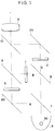
- a conventional image forming apparatus is exemplified by a projector shown in Fig. 1.
- Light emitted from a light source 30 directly or through a reflector 5 is color-separated into red, green, and blue light components by a dichroic mirror 7 for reflecting the red light component and transmitting the green and blue light components therethrough and a dichroic mirror 8 for reflecting the blue light component and transmitting the green light component therethrough and a total reflection mirror 20.
- the color-separated light components pass through liquid crystal light valves 1, 2, and 3 and are synthesized through a dichroic mirror 9 for reflecting the blue light component and transmitting the red light component therethrough and a dichroic mirror 10 for reflecting the green light component and transmitting the red and blue light components therethrough.
- the synthesized light is projected through a projection lens 6.
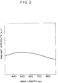
- a metal halide lamp having spectral characteristics in the entire visible light range, as shown in Fig. 2 is used as the light source 30.
- a color-separating optical system is located between the light source and the liquid crystal light valves, and optical paths between the light source and the liquid crystal light valves must have predetermined lengths.
- Illumination light from the light source cannot be perfect telecentric light and contains convergent and divergent components. For this reason, the illumination light has a considerably large loss by divergence during propagation along the optical paths having the predetermined lengths.
- the color-separating optical system causes an increase in the size of the apparatus as a whole, thereby degrading portability of the apparatus.
- a single light valve type liquid crystal projector which has one white light source and one liquid crystal light valve having an RGB mosaic color filter.
- This arrangement allows formation of a projector by one liquid crystal light valve, and the color-separating optical system and the color-synthesizing optical system can be omitted, thereby realizing a very compact apparatus.
- the following problems are still posed by this apparatus.
- the color filter is generally of an absorption type, the amount of white light passing through the color filter is reduced to about 1/3. For this reason, the transmittance of the liquid crystal light valve is reduced, and hence a sufficiently bright display image cannot be obtained.
- an image forming apparatus having a plurality of imaging means for forming color-separated images and color-synthesizing means for synthesizing the image light components from the plurality of imaging means, characterized by comprising a plurality of light sources, wherein the plurality of imaging means are illuminated with different color light components.
- a projector comprising an elliptical reflector and a light source located near one focal point of the elliptical reflector and a projection lens located such that a pupil thereof is located near the other focal point of the elliptical reflector, wherein imaging means is located at a position equidistantly spaced apart from both the focal points, so that non-image light reflected by the imaging means is directed near the light source.
- a projector having a reflector of a shape having at least one focal point, a light source arranged near the focal point, imaging means for modulating light from the light source to form an image, and a mosaic color filter for color-separating the light incident on the imaging means into red, green, and blue light components in a mosaic distribution, wherein the mosaic color filer comprises an interference filter for transmitting any of the red, green, and blue light components and reflecting remaining color components, and the reflected remaining light components are directed near the light source.
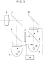
- Fig. 3 is a schematic view showing an arrangement of an embodiment of the present invention.
- Light valves 1, 2, and 3 as imaging means form color images corresponding to the blue, green, and red light components, respectively.
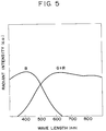
- An apparatus in Fig. 3 also includes a projection lens 6, dichroic mirrors 8, 9, and 11, a total reflection mirror 20, and color light sources 31 and 32 having spectral characteristics represented by B and G+R, respectively, as shown in Fig. 5. More specifically, the light source 31 is a blue light source, and the light source 32 is a yellow light source having green and red spectra.
- the light source 32 may be constituted by green and red light sources which are arranged adjacent to each other.
- the blue light source 31 is located immediately behind the liquid crystal light valve 1. For this reason, the length of the illumination optical path can be reduced to 1/4 or less of the conventional apparatus shown in Fig. 1. Illumination light emitted from the yellow light source 32 is color-separated into red and green light components by the dichroic mirror 8. The red and green light components are radiated on the liquid crystal light valves 2 and 3, respectively. The length of the optical path can be reduced to about 1/2 the conventional apparatus shown in Fig. 1 in which light components reach the liquid crystal light valves 2 and 3 through two dichroic mirrors. The loss of the divergent illumination light can be greatly reduced, and a brighter image forming apparatus can be arranged.
- the light components pass through the liquid crystal light valves 1, 2, and 3, they are synthesized again through the total reflection mirror 20, the dichroic mirror 9 for transmitting the blue light component and reflecting the green component, and the dichroic mirror 11 for transmitting the red light component and reflecting the green and blue light components.
- the synthesized light is projected through the projection lens 6.
- the dichroic mirrors 8 and 11 are designed to transmit the red light component and reflect the blue and green light components, the dichroic mirrors 8 and 11 can be identical to each other, thus resulting in an economical advantage. At this time, if the dichroic mirrors 8 and 11 are constituted by a single dichroic mirror, the number of optical elements and the number of positioning operations can be reduced.
- Man's eye is most sensitive to the green light component among the components in the visible range.
- an astigmatism occurs. Judging from these two factors, it is found that the number of times of passing of the green light component through a dichroic mirror can be reduced to obtain a high resolving power.
- a display image having a high resolving power can be obtained.
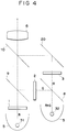
- Fig. 4 is a schematic view showing an arrangement of another embodiment according to the present invention.
- Light valves 1, 2, and 3 as imaging means form color images corresponding to the blue, green, and red light components, respectively.
- An apparatus in Fig. 4 also includes a projection lens 6, dichroic mirrors 8, 9, and 10, a total reflection mirror 20, and color light sources 31 and 32 having spectral characteristics represented by B and G+R, respectively, as shown in Fig. 5. More specifically, the light source 31 is a blue light source, and the light source 32 is a yellow light source having green and red spectra.
- These components of the apparatus have a layout, as shown in Fig. 4.
- the blue light source 31 is located immediately behind the liquid crystal light valve 1. For this reason, the length of the illumination optical path can be reduced to 1/4 or less of the conventional apparatus shown in Fig. 1. Illumination light emitted from the yellow light source 32 is color-separated into red and green light components by the dichroic mirror 8. The red and green light components are radiated on the liquid crystal light valves 2 and 3, respectively. The length of the optical path can be reduced to about 1/2 the conventional apparatus shown in Fig. 1 in which light components reach the liquid crystal light valves 2 and 3 through two dichroic mirrors. The loss of the divergent illumination light can be greatly reduced, and a brighter image forming apparatus can be arranged.
- the light components pass through the liquid crystal light valves 1, 2, and 3, they are synthesized again through the total reflection mirror 20, the dichroic mirror 9 for transmitting the blue light component and reflecting the green component, and the dichroic mirror 10 for reflecting the red light component and transmitting the green and blue light components.
- the synthesized light is projected through the projection lens 6.
- the white light source 30 of the conventional projector shown in Fig. 1 often comprises a metal halide lamp.
- Light emitted from a metal halide lamp generally has a shortage of the blue light component.
- some light components having a wavelength of 400 nm or less are absorbed by the dichroic mirror.
- a light source for generating a blue light component which tends to be short is independently prepared, and a light source for emitting the remaining yellow light component (i.e., the green and red light components) is prepared to obtain an excellent color balance, as in the embodiments of Figs. 3 and 4.
- the length of the optical path between the light source 31 for emitting the blue light component and the liquid crystal light valve 1 may be intentionally increased to obtain a length equal to that between the light source 32 for emitting the yellow light component and the liquid crystal light valves 2 and 3. This arrangement much facilitates white balance control.
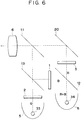
- Fig. 6 is a schematic view showing still another embodiment of the present invention.
- Light valves 1, 2, and 3 as imaging means form color images corresponding to the blue, green, and red light components, respectively.
- An apparatus in Fig. 6 also includes a projection lens 6, dichroic mirrors 11, 12, and 13, a total reflection mirror 20, and color light sources 33 and 34 having spectral characteristics for emitting a green color component and red and blue light components, respectively. These components of the apparatus have a layout, as shown in Fig. 6.
- the green light source 33 is located immediately behind the liquid crystal light valve 2. Illumination light emitted from the color light source 34 is color-separated into red and blue light components by the dichroic mirror 12. The red and blue light components are radiated on the liquid crystal light valves 3 and 1, respectively. As in the previous embodiments described above, the loss of the divergent illumination light can be greatly reduced, and a brighter image forming apparatus can be arranged.
- the respective light components pass through the liquid crystal light valves 1, 2, and 3 and are synthesized again through the total reflection mirror 20, the dichroic mirror 13 for reflecting the blue light component and transmitting the green light component, and the dichroic mirror for transmitting the red light component and reflecting the blue light component.
- the synthesized light is projected through the projection lens 6.
- the dichroic mirrors 11 and 12 are designed to transmit the red light component and reflect the blue and green light components, the dichroic mirrors 11 and 12 can be identical to each other, thus resulting in an economical advantage. At this time, if the dichroic mirrors 11 and 12 are constituted by a single dichroic mirror, the number of optical elements and the number of positioning operations can be reduced.
- Light passing through a dichroic mirror generally has a larger light amount loss than light reflected thereby.
- the blue light component does not pass through a dichroic mirror, the loss of the blue light component can be minimized.
- the length of the optical path between the light source 33 for emitting the green light component and the liquid crystal light valve 2 may be intentionally increased to obtain a length equal to that between the light source 34 for emitting the red and blue light components and the liquid crystal light valves 1 and 3. This arrangement much facilitates white balance control. If the dichroic mirror 11 is replaced with the dichroic mirror 10 for reflecting the red light component and transmitting the green and blue light components, the projection direction can be shifted by 90° as in the embodiment shown in Fig. 4.
- Fig. 7 is a schematic view showing still another embodiment of the present invention.
- Liquid crystal light valves 1, 2, and 3 as imaging means form color images corresponding to the blue, green, and red light components.
- An apparatus in Fig. 7 also includes a projection lens 6, dichroic films 14 and 15 formed at the interfaces of prisms, and color light sources 31, 33, and 35 having spectral characteristics for generating the blue, green, and red color components, respectively. These components have a layout, as shown in Fig. 7.
- the blue light source 31 is located immediately behind the liquid crystal light valve 1, so that the length of the illumination optical path is 1/4 or less that of the conventional example in Fig. 1. This also applies to the green and red light sources 33 and 35.
- the respective light components pass through the liquid crystal light valves 1, 2, and 3, they are synthesized again through the dichroic film 14 for reflecting only the blue light component and the dichroic film 15 for reflecting only the green light component.
- the synthesized light is projected through the projection lens 6.
- a combination of a dichroic film for reflecting only the blue light component and a dichroic film for reflecting only the red light component is more preferable.
- the imaging means corresponding to the R, G, and B light components are illuminated with the R, G, and B light sources, respectively, so that an image forming apparatus having a very high luminance can be realized.
- the light amount is greatly reduced.
- light sources for emitting appropriate color light components are used, light utilization efficiency can be greatly improved.
- the dichroic prism is used as a color synthesis optical system.
- a crossed dichroic mirror as a combination of the dichroic mirrors described above may be used.
- the color light sources described in each embodiment may have spectra matching desired conditions.
- a light source having a line spectrum is better than a light source having a wide emission spectrum because the width of chromaticity increases.
- a combination of a light source having a larger amount of red light component than other components and a red filter for increasing purity of the red light component can be used.
- this combination is far better than the conventional arrangement obtained by attaching a color filter to a white light source when the total light efficiency including the blue and green light components is considered.
- Color filters may be used for color light sources except for the red light source to increase the color purities of other light components.
- a light amount adjusting means 73 as a means for correcting the white balance error may be arranged in each embodiment described above. Part of the synthesized light is directly received as white balance information or part of light reflected by a screen (not shown) upon incidence of the synthesized light is received as the white balance information while each liquid crystal light valve is set in a light-transmitting state.
- the white balance information is input to the illustrated light amount adjusting means 73.
- the light amount adjusting means 73 adjusts the light amount of at least one light source on the basis of the white balance information.
- the liquid crystal light valve serves as both the image forming means and the light amount adjusting means.
- an ND filter is movably arranged to be inserted in an optical path as needed so as to perform light amount adjustment.
- FIG. 8 shows still another embodiment of the present invention exemplifying its optical system.
- a reflector 43 comprises a cold mirror having a shape of a rotating ellipsoid. This ellipsoid has points a and b as focal points thereof.
- a light source 30 is located at the focal point b and the pupil of a projection lens 6 is located at the focal point a .
- a liquid crystal light valve 41 is located at the middle position between the focal points a and b and is conjugate to a screen (not shown) through the projection lens 6. For this reason, as indicated by broken lines, light rays from the light source 30 and the reflector 43 are focused at an aperture of the projection lens 6 after the light rays pass through the liquid crystal light valve 41.
- a so-called Köhler illumination system is formed without using any condenser lens.
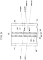
- Fig. 9 is an enlarged sectional view of the liquid crystal light valve 41.
- a liquid crystal layer 65 is sandwiched between a TFT substrate 57 having TFTs, wiring lines 67, and transparent pixel electrodes 68, and a counter substrate 56 having an interference color filter 60 having R, G, and B phosphors in a mosaic shape, a total reflection film 61, and a transparent counterelectrode 63.
- Polarizing plates 54 and 55 are adhered to the outer surfaces of the substrates 56 and 57 in a parallel-Nicols state. In this case, a normally black mode is set.
- the interference color filter 60 is arranged in correspondence with the effective display area of each pixel, and the total reflection film 61 is formed in correspondence with a non-effective display area of each TFT and wiring line.
- the characteristic feature of this liquid crystal valve lies in a multilayered interference type color filter as the color filter. These layers of the multilayered film can be formed by photolithography such as multilayered film deposition or ion beam etching.
- White illumination light W(P+S) as nonpolarized light from the light source and the reflector is converted into a white linearly polarized light component W(P) through the polarizing plate 54 and is converted into monochrome linearly polarized light components such as G(P) and R(P) by the interference color filter 60. These light components are incident on the liquid crystal pixels.
- the linearly polarized light components such as R+B(P) and G+B(P) reflected by the interference color filter return to the light source 30, as indicated by the broken lines in Fig. 8 because the liquid crystal light valve 41 is located at the middle position between the focal points a and b of the ellipsoid. Light returning to the light source 30 is directed again toward the light crystal light valve 41.
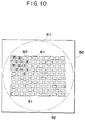
- Fig. 10 is a plan view showing the liquid crystal light valve 41 when viewed from the light source.
- the interference color filter 60 having R, G, and B components corresponding to the pixels is formed in a display area 51 in a mosaic shape.
- the non-effective display area between the pixels except for the display area is covered with the total reflection film 61 formed on the transparent counter substrate 56.
- a circle 52 indicated by the alternate long and short dashed line in Fig. 10 represents an illumination area by the reflector 43 and the light source 30. Of illumination light which illuminates the illumination area 52, illumination light components reaching the non-display area are reflected by the total reflection film 61. This reflected light returns to the light source 30 together with the light reflected by the interference color filter 60, as indicated by the broken lines in Fig. 8. The return light is then directed again toward the liquid crystal light valve 41.
- the non-effective light which is absorbed and disappears in the absorption type color filter and a light-shielding mask can return to the light source, this light can be utilized as illumination light again. That is, a return/reutilization loop is formed, and the light utilization efficiency of the illumination light can be greatly improved. Therefore, a brighter image forming apparatus can be realized.
- a Köhler illumination system can be formed in front of the liquid crystal light valve (i.e., on the light source side) without using any condenser lens.
- the reflector has a shape of an ellipsoid, but a hyperbolic reflector can be used to obtain the same effect as described above.
- FIG. 11 shows still another embodiment exemplifying its optical system.
- a reflector 53 comprises a cold mirror having a shape of a rotating ellipsoid. This ellipsoid has points a and b as its focal points as in the above embodiment.
- a light source 30 is located at the focal point b and the pupil of a projection lens 6 is located at the focal point a .
- a liquid crystal light valve 42 is located at the middle position between the focal points a and b .
- a polarizing beam splitter 45 adhered with a total reflection mirror 20 is located between the liquid crystal light valve 42 and the reflector 53 to constitute a return type polarizing conversion system.
- Illumination light (non-polarized light) emitted from the light source 30 through the reflector 53 is split by a polarizing beam splitter surface 4 into a p-polarized light component having a polarization plane parallel to the drawing surface and an s-polarized light component having a polarization plane perpendicular to the drawing surface.
- the p-polarized light component passes through the polarizing beam splitter surface 4 and illuminates the liquid crystal light valve 42.
- the s-polarized light component is reflected by the polarizing beam splitter surface 4, reflected again by the total reflection mirror 20, and is reflected by the polarizing beam splitter surface 4.
- This reflected light returns to the light source 30 because the position of the mirror surface 20 is located at a position equivalent to the middle position between the focal points a and b .
- the reflector 53 reflects the s-polarized light component using the light source 30 as a secondary source, the s-polarized light component is scattered by the bulb portion of the light source 30 or reflected by the reflector 53 to disturb the polarization plane.
- the light having the disturbed polarization plane is split again by the polarizing beam splitter surface into p- and s-polarized light components.
- the liquid crystal light valve 42 has a mode for polarizing the p-polarized light component.
- the mode is selected such that the liquid crystal light valve 42 modulates the s-polarized light component, the positions of the liquid crystal light valve 42 and the total reflection mirror 20 need only be reversed.
- the illumination light is focused at the aperture of the projection lens 6 by the focusing effect of the elliptical reflector 53 upon transmission through the liquid crystal light valve, as in the embodiment described above.
- a so-called Köhler illumination system can be formed without using any condenser lens.
- the liquid crystal light valve 42 has the same basic arrangement as that of the liquid crystal light valve 41 shown in Fig. 9 except for the incident-side polarizing plate 54.
- Light reflected by an interference color film 60 and the total reflection mirror 61 passes through a polarizing beam splitter 45 and returns to the light source 30 as in the above embodiment.
- illumination light is polarized and converted, thereby further improving the light utilization efficiency, and a brighter image forming apparatus can be realized.
- An incident-side polarizing plate 54 as in the above embodiment can be arranged to increase the polarization ratio in this embodiment.
- a polarizing beam splitter As a polarizing beam splitter, a plurality of parallel flat plates such as glass plates may be used overlapping each other in place of the prism type beam splitter. In this case, light is caused to become incident at a Brewster angle to split it into s- and p-polarized light components.
- This embodiment can realize a lighter apparatus.
- Fig. 12 is a view showing an optical system according to still another embodiment.
- the embodiment in Fig. 12 is different from that of Fig. 8 in that a grid polarizing plate 49 is located on the light source side of a liquid crystal light valve.
- Fig. 13 is an enlarged sectional view of this liquid crystal light valve 42 and the grid polarizing plate 49.
- the grid polarizing plate 49 is obtained by forming a metal grid (lattice) 58 on the surface of a transparent grid substrate 59 of quartz, glass, or the like.
- the pitch of the grid lines is preferably 50 nm or less.
- This grid can be formed by X-ray lithography or ion beam drawing.
- the grid polarizing plate is described in detail in Appl. Optics 6 (1967), 1023 or the like.
- White illumination light W(P+S) as non-polarized light from the light source and the reflector is split into s- and p-polarized light components by a grid 58. More specifically, an s-polarized light component W(S) is reflected, and a p-polarized light component W(P) passes to illuminate the liquid crystal light valve 42. Since the grid 58 is located at the middle position between the focal points a and b of the elliptical reflector 43, the reflected s-polarized light component W(S) returns to a portion near the light source 30.
- a non-effective light component reflected by the interference color filter 60 and the total reflection film 61 also returns to a portion near the light source 30 because the reflection position is near the grid 58.
- the s-polarized light component returning to the light source 30 has a disturbed polarization plane, and part of it serves as illumination light for the liquid crystal light valve 42.
- the non-effective light components reflected by the interference color filter 60 and the total reflection film 61 are also utilized as illumination light for the liquid crystal light valve 42 through the light source 30 and the reflector 43.
- a brighter image forming apparatus obtained by return/reutilization and polarization of the illumination light can be realized by a very simple arrangement shown in Fig. 12.
- a hyperbolic reflector may be used in place of the elliptical reflector 43 in this embodiment.
- the hyperbolic reflector is better than the elliptical reflector due to the following reason.
- Fig. 11 when the elliptical reflector is used, return light is reflected by the reflector and emerges.
- the hyperbolic reflector when the hyperbolic reflector is used, light is reflected twice and emerges, so that the polarization plane is disturbed much.
- the elliptical reflector is advantageous over the hyperbolic reflector. Therefore, these two reflectors can be appropriately used in accordance with application purposes.
- Fig. 14 shows still another embodiment which exemplifies a direct viewing type image forming apparatus without using a projection lens.
- the arrangement of this embodiment is substantially the same as that of Fig. 8 except for the projection lens 6, and a detailed description thereof will be omitted.
- the apparatus of the embodiment shown in Fig. 14 has a cabinet 71 and a diffusion plate 72 for increasing the field angle.
- the embodiments shown in Figs. 3, 4, 6, 7, 11, and 12 can equally cope with direct viewing type apparatuses.
- the imaging means is not limited to the liquid crystal light valve. Any optical element such as a PLZT or the like may be used if it can change the state of the polarized light to obtain information light.
- the means for splitting light from the light source into the p- and s-polarized light components is not limited to the polarizing beam splitter. Any optical element such as a birefringent lens made of an optically uniaxial material, a Wollaston prism, a Glan-Thompson prism, and a cholesteric liquid crystal layer if it can split light into a pair of different polarized beam components.
- the present invention is not limited to a projector or a direct viewing type display apparatus, but can be extended to a recording apparatus such as a liquid crystal printer.
- an image forming apparatus having a plurality imaging means for forming color-separated images and color-synthesizing means for synthesizing the image light components from the plurality of imaging means, characterized by comprising a plurality of light sources, wherein the plurality of imaging means are illuminated with different color light components.
- a projector comprising an elliptical reflector and a light source located near one focal point of the elliptical reflector and a projection lens located such that a pupil thereof is located near the other focal point of the elliptical reflector, wherein imaging means is located at a position equidistantly spaced apart from both the focal points, so that non-image light reflected by the imaging means is directed near the light source.
- a projector having a reflector of a shape having at least one focal point, a light source arranged near the focal point, imaging means for modulating light from the light source to form an image, and a mosaic color filter for color-separating the light incident on the imaging means into red, green, and blue light components in a mosaic distribution, wherein the mosaic color filer comprises an interference filter for transmitting any of the red, green, and blue light components and reflecting remaining color components, and the reflected remaining light components are directed near the light source.
- the mosaic color filer comprises an interference filter for transmitting any of the red, green, and blue light components and reflecting remaining color components, and the reflected remaining light components are directed near the light source.
- An image forming apparatus of this invention relates to an image forming apparatus for forming a color image and, more particularly, to a projector using the image forming apparatus.
- the image forming apparatus includes a color light illuminating system having first and second light sources for emitting different color light components, and first, second, and third imaging units or liquid crystal light valves for modulating the color light components to form color images.
- the first light source is a light source for mainly emitting two color components corresponding to the images formed by the first and second imaging units
- the second light source is a color light source for mainly emitting a color component corresponding to the image formed by the third imaging unit.
Abstract
Description
- The present invention relates to an image forming apparatus for forming a color image and, more particular, a projector using the same.
- A conventional image forming apparatus is exemplified by a projector shown in Fig. 1.
- Light emitted from a
light source 30 directly or through areflector 5 is color-separated into red, green, and blue light components by adichroic mirror 7 for reflecting the red light component and transmitting the green and blue light components therethrough and adichroic mirror 8 for reflecting the blue light component and transmitting the green light component therethrough and atotal reflection mirror 20. The color-separated light components pass through liquidcrystal light valves dichroic mirror 9 for reflecting the blue light component and transmitting the red light component therethrough and adichroic mirror 10 for reflecting the green light component and transmitting the red and blue light components therethrough. The synthesized light is projected through aprojection lens 6. - A metal halide lamp having spectral characteristics in the entire visible light range, as shown in Fig. 2 is used as the
light source 30. - In the conventional apparatus, a color-separating optical system is located between the light source and the liquid crystal light valves, and optical paths between the light source and the liquid crystal light valves must have predetermined lengths. Illumination light from the light source cannot be perfect telecentric light and contains convergent and divergent components. For this reason, the illumination light has a considerably large loss by divergence during propagation along the optical paths having the predetermined lengths. In addition, the color-separating optical system causes an increase in the size of the apparatus as a whole, thereby degrading portability of the apparatus.
- As one method of solving these conventional problems, there may be proposed a single light valve type liquid crystal projector which has one white light source and one liquid crystal light valve having an RGB mosaic color filter. This arrangement allows formation of a projector by one liquid crystal light valve, and the color-separating optical system and the color-synthesizing optical system can be omitted, thereby realizing a very compact apparatus. However, the following problems are still posed by this apparatus.
- As the color filter is generally of an absorption type, the amount of white light passing through the color filter is reduced to about 1/3. For this reason, the transmittance of the liquid crystal light valve is reduced, and hence a sufficiently bright display image cannot be obtained.
- It is an object of the present invention to provide a compact image forming apparatus having a high light utilization efficiency and a high resolving power and a projector using the same.
- In order to achieve the above object according to an aspect of the present invention, there is provided an image forming apparatus having a plurality of imaging means for forming color-separated images and color-synthesizing means for synthesizing the image light components from the plurality of imaging means, characterized by comprising a plurality of light sources, wherein the plurality of imaging means are illuminated with different color light components.
- According to another aspect of the present invention, there is provided a projector comprising an elliptical reflector and a light source located near one focal point of the elliptical reflector and a projection lens located such that a pupil thereof is located near the other focal point of the elliptical reflector, wherein imaging means is located at a position equidistantly spaced apart from both the focal points, so that non-image light reflected by the imaging means is directed near the light source.
- According to still another aspect of the present invention, there is provided a projector having a reflector of a shape having at least one focal point, a light source arranged near the focal point, imaging means for modulating light from the light source to form an image, and a mosaic color filter for color-separating the light incident on the imaging means into red, green, and blue light components in a mosaic distribution, wherein the mosaic color filer comprises an interference filter for transmitting any of the red, green, and blue light components and reflecting remaining color components, and the reflected remaining light components are directed near the light source.
-
- Fig. 1 is a schematic view showing an arrangement of a conventional projector;
- Fig. 2 is a graph showing the spectral characteristics of a white light source used in the conventional projector;
- Fig. 3 is a schematic view showing an arrangement of an embodiment of the present invention;
- Fig. 4 is a schematic view showing an arrangement of another embodiment of the present invention;
- Fig. 5 is a graph showing the spectral characteristics of a color light source used in the embodiments of the present invention;
- Fig. 6 is a schematic view showing an arrangement of still another embodiment of the present invention;
- Fig. 7 is a schematic view showing an arrangement of still another embodiment of the present invention;
- Fig. 8 is a schematic view showing an arrangement of still another embodiment of the present invention;
- Fig. 9 is an enlarged sectional view of a liquid crystal light valve according to still another embodiment of the present invention;
- Fig. 10 is a view showing an arrangement of a color filter according to still another embodiment of the present invention;
- Fig. 11 is a schematic view showing an arrangement of still another embodiment of the present invention;
- Fig. 12 is a schematic view showing an arrangement of still another embodiment of the present invention;
- Fig. 13 is an enlarged sectional view of a liquid crystal light valve according to still another embodiment of the present invention; and
- Fig. 14 is a schematic view showing still another embodiment of the present invention.
- Fig. 3 is a schematic view showing an arrangement of an embodiment of the present invention.
Light valves projection lens 6,dichroic mirrors total reflection mirror 20, andcolor light sources light source 31 is a blue light source, and thelight source 32 is a yellow light source having green and red spectra. These components of the apparatus have a layout, as shown in Fig. 3. Thelight source 32 may be constituted by green and red light sources which are arranged adjacent to each other. - The
blue light source 31 is located immediately behind the liquidcrystal light valve 1. For this reason, the length of the illumination optical path can be reduced to 1/4 or less of the conventional apparatus shown in Fig. 1. Illumination light emitted from theyellow light source 32 is color-separated into red and green light components by thedichroic mirror 8. The red and green light components are radiated on the liquidcrystal light valves crystal light valves - Note that combinations of the color filters and a white light source may be used in place of the blue and yellow light sources described above.
- After the light components pass through the liquid
crystal light valves total reflection mirror 20, thedichroic mirror 9 for transmitting the blue light component and reflecting the green component, and thedichroic mirror 11 for transmitting the red light component and reflecting the green and blue light components. The synthesized light is projected through theprojection lens 6. - In this embodiment, if the
dichroic mirrors dichroic mirrors dichroic mirrors - Man's eye is most sensitive to the green light component among the components in the visible range. On the other hand, when light is obliquely incident on parallel flat plates, as in this embodiment, an astigmatism occurs. Judging from these two factors, it is found that the number of times of passing of the green light component through a dichroic mirror can be reduced to obtain a high resolving power. In this embodiment, since the green light component does not pass through a dichroic mirror, a display image having a high resolving power can be obtained.
- Fig. 4 is a schematic view showing an arrangement of another embodiment according to the present invention.
Light valves projection lens 6,dichroic mirrors total reflection mirror 20, andcolor light sources light source 31 is a blue light source, and thelight source 32 is a yellow light source having green and red spectra. These components of the apparatus have a layout, as shown in Fig. 4. - The
blue light source 31 is located immediately behind the liquidcrystal light valve 1. For this reason, the length of the illumination optical path can be reduced to 1/4 or less of the conventional apparatus shown in Fig. 1. Illumination light emitted from the yellowlight source 32 is color-separated into red and green light components by thedichroic mirror 8. The red and green light components are radiated on the liquidcrystal light valves crystal light valves - After the light components pass through the liquid
crystal light valves total reflection mirror 20, thedichroic mirror 9 for transmitting the blue light component and reflecting the green component, and thedichroic mirror 10 for reflecting the red light component and transmitting the green and blue light components. The synthesized light is projected through theprojection lens 6. - With this arrangement, the direction of a projection image can be shifted from that of the embodiment of Fig. 3 by 90°.
- The
white light source 30 of the conventional projector shown in Fig. 1 often comprises a metal halide lamp. Light emitted from a metal halide lamp generally has a shortage of the blue light component. In addition, when light passes through or reflected by a dichroic mirror, some light components having a wavelength of 400 nm or less are absorbed by the dichroic mirror. - When the above factors are taken into consideration, a light source for generating a blue light component which tends to be short is independently prepared, and a light source for emitting the remaining yellow light component (i.e., the green and red light components) is prepared to obtain an excellent color balance, as in the embodiments of Figs. 3 and 4. Alternatively, the length of the optical path between the
light source 31 for emitting the blue light component and the liquid crystallight valve 1 may be intentionally increased to obtain a length equal to that between thelight source 32 for emitting the yellow light component and the liquidcrystal light valves - Fig. 6 is a schematic view showing still another embodiment of the present invention.
Light valves projection lens 6,dichroic mirrors total reflection mirror 20, andcolor light sources - The
green light source 33 is located immediately behind the liquid crystallight valve 2. Illumination light emitted from thecolor light source 34 is color-separated into red and blue light components by thedichroic mirror 12. The red and blue light components are radiated on the liquidcrystal light valves - The respective light components pass through the liquid
crystal light valves total reflection mirror 20, thedichroic mirror 13 for reflecting the blue light component and transmitting the green light component, and the dichroic mirror for transmitting the red light component and reflecting the blue light component. The synthesized light is projected through theprojection lens 6. - In this embodiment, if the
dichroic mirrors dichroic mirrors - Light passing through a dichroic mirror generally has a larger light amount loss than light reflected thereby. In this embodiment, the blue light component does not pass through a dichroic mirror, the loss of the blue light component can be minimized.
- Alternatively, the length of the optical path between the
light source 33 for emitting the green light component and the liquid crystallight valve 2 may be intentionally increased to obtain a length equal to that between thelight source 34 for emitting the red and blue light components and the liquidcrystal light valves dichroic mirror 11 is replaced with thedichroic mirror 10 for reflecting the red light component and transmitting the green and blue light components, the projection direction can be shifted by 90° as in the embodiment shown in Fig. 4. - Fig. 7 is a schematic view showing still another embodiment of the present invention. Liquid
crystal light valves projection lens 6,dichroic films color light sources - The blue
light source 31 is located immediately behind the liquid crystallight valve 1, so that the length of the illumination optical path is 1/4 or less that of the conventional example in Fig. 1. This also applies to the green andred light sources - After the respective light components pass through the liquid
crystal light valves dichroic film 14 for reflecting only the blue light component and thedichroic film 15 for reflecting only the green light component. The synthesized light is projected through theprojection lens 6. - When ease in design of the dichroic films is to be preferentially considered, a combination of a dichroic film for reflecting only the blue light component and a dichroic film for reflecting only the red light component is more preferable.
- In this embodiment, the imaging means corresponding to the R, G, and B light components are illuminated with the R, G, and B light sources, respectively, so that an image forming apparatus having a very high luminance can be realized. As in the conventional example, when a color filter is attached to a white light source, the light amount is greatly reduced. In this embodiment and each embodiment described above, since light sources for emitting appropriate color light components are used, light utilization efficiency can be greatly improved.
- In this embodiment, the dichroic prism is used as a color synthesis optical system. However, a crossed dichroic mirror as a combination of the dichroic mirrors described above may be used.
- The color light sources described in each embodiment may have spectra matching desired conditions. In this case, a light source having a line spectrum is better than a light source having a wide emission spectrum because the width of chromaticity increases. As it is difficult to prepare a light source for a pure red light component at present, a combination of a light source having a larger amount of red light component than other components and a red filter for increasing purity of the red light component can be used. In this case, although the amount of red light component is slightly reduced by the filter, this combination is far better than the conventional arrangement obtained by attaching a color filter to a white light source when the total light efficiency including the blue and green light components is considered. Color filters may be used for color light sources except for the red light source to increase the color purities of other light components. Since these filters are used to increase the color purities, light amount losses are small. Note that as color light source materials in a metal halide lamp, sodium (Na-), indium (In-), and thallium (Tl-fased) gases are mixed for red, blue, and green, respectively, in addition to mercury.
- In each embodiment described above, use of a plurality of light sources may cause unbalance in light amounts between the plurality of light sources with a lapse of time. An error occurs in white balance accordingly. A light amount adjusting means 73 as a means for correcting the white balance error may be arranged in each embodiment described above. Part of the synthesized light is directly received as white balance information or part of light reflected by a screen (not shown) upon incidence of the synthesized light is received as the white balance information while each liquid crystal light valve is set in a light-transmitting state. The white balance information is input to the illustrated light amount adjusting means 73. The light amount adjusting means 73 adjusts the light amount of at least one light source on the basis of the white balance information. For example, in the embodiment shown in Fig. 3, the liquid crystal light valve serves as both the image forming means and the light amount adjusting means. In the embodiment shown in Fig. 7, an ND filter is movably arranged to be inserted in an optical path as needed so as to perform light amount adjustment.
- Fig. 8 shows still another embodiment of the present invention exemplifying its optical system. A
reflector 43 comprises a cold mirror having a shape of a rotating ellipsoid. This ellipsoid has points a and b as focal points thereof. Alight source 30 is located at the focal point b and the pupil of aprojection lens 6 is located at the focal point a. A liquid crystallight valve 41 is located at the middle position between the focal points a and b and is conjugate to a screen (not shown) through theprojection lens 6. For this reason, as indicated by broken lines, light rays from thelight source 30 and thereflector 43 are focused at an aperture of theprojection lens 6 after the light rays pass through the liquid crystallight valve 41. A so-called Köhler illumination system is formed without using any condenser lens. - Fig. 9 is an enlarged sectional view of the liquid crystal
light valve 41. Aliquid crystal layer 65 is sandwiched between aTFT substrate 57 having TFTs,wiring lines 67, andtransparent pixel electrodes 68, and acounter substrate 56 having aninterference color filter 60 having R, G, and B phosphors in a mosaic shape, atotal reflection film 61, and atransparent counterelectrode 63. Polarizingplates substrates interference color filter 60 is arranged in correspondence with the effective display area of each pixel, and thetotal reflection film 61 is formed in correspondence with a non-effective display area of each TFT and wiring line. The characteristic feature of this liquid crystal valve lies in a multilayered interference type color filter as the color filter. These layers of the multilayered film can be formed by photolithography such as multilayered film deposition or ion beam etching. - White illumination light W(P+S) as nonpolarized light from the light source and the reflector is converted into a white linearly polarized light component W(P) through the
polarizing plate 54 and is converted into monochrome linearly polarized light components such as G(P) and R(P) by theinterference color filter 60. These light components are incident on the liquid crystal pixels. On the other hand, the linearly polarized light components such as R+B(P) and G+B(P) reflected by the interference color filter return to thelight source 30, as indicated by the broken lines in Fig. 8 because the liquid crystallight valve 41 is located at the middle position between the focal points a and b of the ellipsoid. Light returning to thelight source 30 is directed again toward the lightcrystal light valve 41. - Fig. 10 is a plan view showing the liquid crystal
light valve 41 when viewed from the light source. Theinterference color filter 60 having R, G, and B components corresponding to the pixels is formed in adisplay area 51 in a mosaic shape. The non-effective display area between the pixels except for the display area is covered with thetotal reflection film 61 formed on thetransparent counter substrate 56. Acircle 52 indicated by the alternate long and short dashed line in Fig. 10 represents an illumination area by thereflector 43 and thelight source 30. Of illumination light which illuminates theillumination area 52, illumination light components reaching the non-display area are reflected by thetotal reflection film 61. This reflected light returns to thelight source 30 together with the light reflected by theinterference color filter 60, as indicated by the broken lines in Fig. 8. The return light is then directed again toward the liquid crystallight valve 41. - According to this embodiment, since the non-effective light which is absorbed and disappears in the absorption type color filter and a light-shielding mask can return to the light source, this light can be utilized as illumination light again. That is, a return/reutilization loop is formed, and the light utilization efficiency of the illumination light can be greatly improved. Therefore, a brighter image forming apparatus can be realized. In addition, a Köhler illumination system can be formed in front of the liquid crystal light valve (i.e., on the light source side) without using any condenser lens.
- In this embodiment, the reflector has a shape of an ellipsoid, but a hyperbolic reflector can be used to obtain the same effect as described above.
- Fig. 11 shows still another embodiment exemplifying its optical system. A
reflector 53 comprises a cold mirror having a shape of a rotating ellipsoid. This ellipsoid has points a and b as its focal points as in the above embodiment. Alight source 30 is located at the focal point b and the pupil of aprojection lens 6 is located at the focal point a. A liquid crystallight valve 42 is located at the middle position between the focal points a and b. - A
polarizing beam splitter 45 adhered with atotal reflection mirror 20 is located between the liquid crystallight valve 42 and thereflector 53 to constitute a return type polarizing conversion system. Illumination light (non-polarized light) emitted from thelight source 30 through thereflector 53 is split by a polarizing beam splitter surface 4 into a p-polarized light component having a polarization plane parallel to the drawing surface and an s-polarized light component having a polarization plane perpendicular to the drawing surface. - The p-polarized light component passes through the polarizing beam splitter surface 4 and illuminates the liquid crystal
light valve 42. The s-polarized light component is reflected by the polarizing beam splitter surface 4, reflected again by thetotal reflection mirror 20, and is reflected by the polarizing beam splitter surface 4. This reflected light returns to thelight source 30 because the position of themirror surface 20 is located at a position equivalent to the middle position between the focal points a and b. In the process in which thereflector 53 reflects the s-polarized light component using thelight source 30 as a secondary source, the s-polarized light component is scattered by the bulb portion of thelight source 30 or reflected by thereflector 53 to disturb the polarization plane. The light having the disturbed polarization plane is split again by the polarizing beam splitter surface into p- and s-polarized light components. By repeating this process, almost all the light emitted from thelight source 30 are polarized into the p-polarized components which are then incident on the liquid crystallight valve 42. The liquid crystallight valve 42 has a mode for polarizing the p-polarized light component. However, when the mode is selected such that the liquid crystallight valve 42 modulates the s-polarized light component, the positions of the liquid crystallight valve 42 and thetotal reflection mirror 20 need only be reversed. - The illumination light is focused at the aperture of the
projection lens 6 by the focusing effect of theelliptical reflector 53 upon transmission through the liquid crystal light valve, as in the embodiment described above. A so-called Köhler illumination system can be formed without using any condenser lens. The liquid crystallight valve 42 has the same basic arrangement as that of the liquid crystallight valve 41 shown in Fig. 9 except for the incident-sidepolarizing plate 54. Light reflected by aninterference color film 60 and thetotal reflection mirror 61 passes through apolarizing beam splitter 45 and returns to thelight source 30 as in the above embodiment. In addition to the return/reutilization effect of the non-effective light reflected by the liquid crystallight valve 42 as in the above embodiment, illumination light is polarized and converted, thereby further improving the light utilization efficiency, and a brighter image forming apparatus can be realized. - An incident-side
polarizing plate 54 as in the above embodiment can be arranged to increase the polarization ratio in this embodiment. - As a polarizing beam splitter, a plurality of parallel flat plates such as glass plates may be used overlapping each other in place of the prism type beam splitter. In this case, light is caused to become incident at a Brewster angle to split it into s- and p-polarized light components. This embodiment can realize a lighter apparatus.
- Fig. 12 is a view showing an optical system according to still another embodiment. The embodiment in Fig. 12 is different from that of Fig. 8 in that a
grid polarizing plate 49 is located on the light source side of a liquid crystal light valve. Fig. 13 is an enlarged sectional view of this liquid crystallight valve 42 and thegrid polarizing plate 49. - The
grid polarizing plate 49 is obtained by forming a metal grid (lattice) 58 on the surface of atransparent grid substrate 59 of quartz, glass, or the like. The pitch of the grid lines is preferably 50 nm or less. This grid can be formed by X-ray lithography or ion beam drawing. The grid polarizing plate is described in detail in Appl. Optics 6 (1967), 1023 or the like. - The operation of this embodiment will be described below. White illumination light W(P+S) as non-polarized light from the light source and the reflector is split into s- and p-polarized light components by a
grid 58. More specifically, an s-polarized light component W(S) is reflected, and a p-polarized light component W(P) passes to illuminate the liquid crystallight valve 42. Since thegrid 58 is located at the middle position between the focal points a and b of theelliptical reflector 43, the reflected s-polarized light component W(S) returns to a portion near thelight source 30. Of the transmitted p-polarized light component W(P), a non-effective light component reflected by theinterference color filter 60 and thetotal reflection film 61 also returns to a portion near thelight source 30 because the reflection position is near thegrid 58. As in the above embodiment, the s-polarized light component returning to thelight source 30 has a disturbed polarization plane, and part of it serves as illumination light for the liquid crystallight valve 42. The non-effective light components reflected by theinterference color filter 60 and thetotal reflection film 61 are also utilized as illumination light for the liquid crystallight valve 42 through thelight source 30 and thereflector 43. - As described above, according to this embodiment, a brighter image forming apparatus obtained by return/reutilization and polarization of the illumination light can be realized by a very simple arrangement shown in Fig. 12.
- A hyperbolic reflector may be used in place of the
elliptical reflector 43 in this embodiment. As previously described above, when the light returning to the light source is reflected by a reflector to preferentially disturb the polarization plane, the hyperbolic reflector is better than the elliptical reflector due to the following reason. As can be apparent from Fig. 11, when the elliptical reflector is used, return light is reflected by the reflector and emerges. However, when the hyperbolic reflector is used, light is reflected twice and emerges, so that the polarization plane is disturbed much. - When the reception angle of light emitted from the light source is taken into consideration, the elliptical reflector is advantageous over the hyperbolic reflector. Therefore, these two reflectors can be appropriately used in accordance with application purposes.
- Fig. 14 shows still another embodiment which exemplifies a direct viewing type image forming apparatus without using a projection lens. The arrangement of this embodiment is substantially the same as that of Fig. 8 except for the
projection lens 6, and a detailed description thereof will be omitted. The apparatus of the embodiment shown in Fig. 14 has acabinet 71 and adiffusion plate 72 for increasing the field angle. The embodiments shown in Figs. 3, 4, 6, 7, 11, and 12 can equally cope with direct viewing type apparatuses. - The present invention is not limited to the particular embodiments described above. Various changes and modifications may be made without departing from the spirit and scope of the invention.
- For example, the imaging means is not limited to the liquid crystal light valve. Any optical element such as a PLZT or the like may be used if it can change the state of the polarized light to obtain information light.
- The means for splitting light from the light source into the p- and s-polarized light components is not limited to the polarizing beam splitter. Any optical element such as a birefringent lens made of an optically uniaxial material, a Wollaston prism, a Glan-Thompson prism, and a cholesteric liquid crystal layer if it can split light into a pair of different polarized beam components.
- The present invention is not limited to a projector or a direct viewing type display apparatus, but can be extended to a recording apparatus such as a liquid crystal printer.
- According to an aspect of the present invention, there is provided an image forming apparatus having a plurality imaging means for forming color-separated images and color-synthesizing means for synthesizing the image light components from the plurality of imaging means, characterized by comprising a plurality of light sources, wherein the plurality of imaging means are illuminated with different color light components.
- According to another aspect of the present invention, there is provided a projector comprising an elliptical reflector and a light source located near one focal point of the elliptical reflector and a projection lens located such that a pupil thereof is located near the other focal point of the elliptical reflector, wherein imaging means is located at a position equidistantly spaced apart from both the focal points, so that non-image light reflected by the imaging means is directed near the light source.
- According to still another aspect of the present invention, there is provided a projector having a reflector of a shape having at least one focal point, a light source arranged near the focal point, imaging means for modulating light from the light source to form an image, and a mosaic color filter for color-separating the light incident on the imaging means into red, green, and blue light components in a mosaic distribution, wherein the mosaic color filer comprises an interference filter for transmitting any of the red, green, and blue light components and reflecting remaining color components, and the reflected remaining light components are directed near the light source. In this manner, an image forming apparatus and a projector, in which color balance is excellent, and light utilization efficiency and resolving power are high, are obtained.
- An image forming apparatus of this invention relates to an image forming apparatus for forming a color image and, more particularly, to a projector using the image forming apparatus. The image forming apparatus includes a color light illuminating system having first and second light sources for emitting different color light components, and first, second, and third imaging units or liquid crystal light valves for modulating the color light components to form color images. The first light source is a light source for mainly emitting two color components corresponding to the images formed by the first and second imaging units, and the second light source is a color light source for mainly emitting a color component corresponding to the image formed by the third imaging unit.
Claims (15)
- An image forming apparatus comprising:
color light illuminating means having first and second light sources for emitting mutually different color light components; and
first, second, and third imaging means for modulating the color light components to form color images,
wherein said first light source is a light source for mainly emitting two color components corresponding to the images formed by said first and second imaging means, and said second light source is a color light source for mainly emitting a color component corresponding to the image formed by said third imaging means. - An apparatus according to claim 1, wherein said color light illuminating means comprises color separating means, arranged in an optical path from said first light source, for separating light into two color light components corresponding to the color images formed by said first and second imaging means.
- An apparatus according to claim 2, wherein said first light source is a color light source for emitting color light mainly containing green and red components, and said second light source is a color light source for emitting color light mainly containing a blue light component.
- An apparatus according to claim 2, wherein said first light source is a color light source for emitting color light mainly containing blue and red components, and said second light source is a color light source for emitting color light mainly containing a green component.
- An apparatus according to claim 3, wherein said color synthesizing means comprises a plurality of dichroic mirrors, and said plurality of dichroic mirrors and said color separating means have functions of reflecting the green light components, respectively.
- An image forming apparatus comprising:
first, second, and third imaging means for forming images corresponding to red, green, blue, respectively;
color synthesizing means for synthesizing image light components from said first, second, and third imaging means; and
first, second, and third light sources for illuminating said first, second, and third imaging means, respectively,
wherein said first, second, and third light sources are color light sources for emitting color light mainly containing color components of the color images formed by said first, second, and third imaging means, respectively. - An apparatus according to claim 6, further comprising light amount adjusting means arranged in optical paths from said first, second, and third light sources, respectively.
- A projector comprising:
a reflector having a substantially elliptical shape;
a light source arranged near one focal point of said reflector;
information forming means for modulating light from said light source to form information; and
a projection lens for projecting information light formed by said information forming means, said projection lens being arranged such that a pupil of said projection lens is located near the other focal point of said reflector,
wherein said information forming means is located at a position substantially equidistantly from the two focal points, so that non-image light reflected by said information forming means of the light emitted from said light source is directed toward a portion near said light source. - A projector according to claim 8, further comprising an interference-type mosaic filter, at a light source side of said information forming means, for transmitting a predetermined color component and reflecting remaining color components so as to focus the light from said light source in a mosaic pattern of red, green, an blue, thereby directing the reflected remaining color component near said light source.
- A projector according to claim 8, wherein said information forming means comprises a liquid crystal light valve, a reflecting surface is formed in a portion between pixels and a portion except for a display area of said light valve, on a light source side of said light valve, thereby directing light reflected by said reflecting surface near said light source.
- A projector according to claim 8, further comprising polarizing converting means, formed between said light source and said information forming means, for splitting the light from said light source into a pair of polarized light components having mutually different polarization states, directing one polarized light component toward said information forming means, and returning the other polarized light component near said light source, so that at least part of said other polarized light component is converted to have a polarization state coinciding with that of said one polarized light component through said light source and said reflector.
- A projector according to claim 11, wherein said polarizing converting means includes a grid polarizer.
- A projector according to claim 11, wherein said polarizing converting means comprises a polarizing beam splitter and a reflecting member for reflecting said other polarized light component, and said reflecting member returns said other polarized light component near said light source through said polarizing beam splitter and is located at a position equivalent to a position substantially equidistantly spaced apart from the two focal points.
- An information forming apparatus comprising:
a reflector of a shape having at least one focal point;
a light source located near the focal point;
information forming means for modulating light from said light source to form information light; and
a mosaic color filter for making the light incident on said information forming means into a mosaic shape of red, green, and blue,
wherein said mosaic color filter is an interference-type filter for transmitting any color component of red, green, and blue and reflecting remaining color components, so that the reflected remaining color components are directed near said light source. - A color information forming apparatus comprising:
color light illuminating means having first and second light sources for emitting different color light components; and
first, second, and third information forming means for modulating the color light components to form color images,
wherein said first light source is a color light source for mainly emitting two color components corresponding to the information light components formed by said first and second information forming means, and said second light source is a color light source for mainly emitting a color component corresponding to the information light component formed by said third information forming means.
Priority Applications (1)
| Application Number | Priority Date | Filing Date | Title |
|---|---|---|---|
| EP01116036A EP1148736A3 (en) | 1992-05-06 | 1993-05-05 | Image forming apparatus and projector using the same |
Applications Claiming Priority (3)
| Application Number | Priority Date | Filing Date | Title |
|---|---|---|---|
| JP113614/92 | 1992-05-06 | ||
| JP11361492 | 1992-05-06 | ||
| JP4113614A JP3015201B2 (en) | 1992-05-06 | 1992-05-06 | Image forming apparatus, projection display apparatus, and light modulation apparatus |
Related Child Applications (1)
| Application Number | Title | Priority Date | Filing Date |
|---|---|---|---|
| EP01116036A Division EP1148736A3 (en) | 1992-05-06 | 1993-05-05 | Image forming apparatus and projector using the same |
Publications (3)
| Publication Number | Publication Date |
|---|---|
| EP0568998A2 true EP0568998A2 (en) | 1993-11-10 |
| EP0568998A3 EP0568998A3 (en) | 1993-12-22 |
| EP0568998B1 EP0568998B1 (en) | 2003-04-16 |
Family
ID=14616684
Family Applications (2)
| Application Number | Title | Priority Date | Filing Date |
|---|---|---|---|
| EP01116036A Withdrawn EP1148736A3 (en) | 1992-05-06 | 1993-05-05 | Image forming apparatus and projector using the same |
| EP93107298A Expired - Lifetime EP0568998B1 (en) | 1992-05-06 | 1993-05-05 | Image forming apparatus and projector using the same |
Family Applications Before (1)
| Application Number | Title | Priority Date | Filing Date |
|---|---|---|---|
| EP01116036A Withdrawn EP1148736A3 (en) | 1992-05-06 | 1993-05-05 | Image forming apparatus and projector using the same |
Country Status (4)
| Country | Link |
|---|---|
| US (1) | US5580142A (en) |
| EP (2) | EP1148736A3 (en) |
| JP (1) | JP3015201B2 (en) |
| DE (1) | DE69332874T2 (en) |
Cited By (10)
| Publication number | Priority date | Publication date | Assignee | Title |
|---|---|---|---|---|
| WO1995034162A2 (en) * | 1994-05-26 | 1995-12-14 | Philips Electronics N.V. | An illumination system for a color image projection |
| EP0711081A3 (en) * | 1994-11-01 | 1996-05-29 | Matsushita Electric Ind Co Ltd | |
| WO1997024871A2 (en) * | 1995-12-27 | 1997-07-10 | Philips Electronics N.V. | Two lamp, single light valve projection system |
| WO1997024870A2 (en) | 1995-12-27 | 1997-07-10 | Philips Electronics N.V. | Three lamp, three light valve projection system |
| EP0865210A2 (en) * | 1997-03-12 | 1998-09-16 | Texas Instruments Incorporated | Improvements in or relating to display systems |
| EP0946065A2 (en) * | 1998-03-26 | 1999-09-29 | Sony Corporation | Color projector |
| WO2000070386A1 (en) * | 1999-05-17 | 2000-11-23 | 3M Innovative Properties Company | Reflective lcd projection system using wide-angle polarizing beam splitter |
| US6296927B1 (en) | 1993-12-21 | 2001-10-02 | 3M Innovative Properties | Optical film |
| US6511183B2 (en) | 2001-06-02 | 2003-01-28 | Koninklijke Philips Electronics N.V. | Digital image projector with oriented fixed-polarization-axis polarizing beamsplitter |
| US7652820B2 (en) | 1997-10-28 | 2010-01-26 | 3M Innovative Properties Company | Reflective LCD projection system using wide-angle cartesian polarizing beam splitter and color separation and recombination prisms |
Families Citing this family (49)
| Publication number | Priority date | Publication date | Assignee | Title |
|---|---|---|---|---|
| JP3015201B2 (en) * | 1992-05-06 | 2000-03-06 | キヤノン株式会社 | Image forming apparatus, projection display apparatus, and light modulation apparatus |
| DE69435173D1 (en) | 1993-12-21 | 2009-01-15 | Minnesota Mining & Mfg | Multilayer optical film |
| KR100417399B1 (en) * | 1996-10-15 | 2004-05-07 | 엘지전자 주식회사 | Liquid crystal projector device |
| US6623122B1 (en) * | 1999-09-30 | 2003-09-23 | Semiconductor Energy Laboratory Co., Ltd. | Light source optical system and projector having first and second lamps of different spectral distributions |
| US8487850B1 (en) | 2000-06-05 | 2013-07-16 | Hewlett-Packard Development Company, L.P. | Multi-source LCD backlight for white balance adjustment |
| US6733139B2 (en) * | 2000-06-05 | 2004-05-11 | Hewlett-Packard Development Company, L.P. | Projector with narrow-spectrum light source to complement broad-spectrum light source |
| US6409349B1 (en) * | 2000-12-01 | 2002-06-25 | Intel Corporation | Enhancing spectral luminosity in projection displays |
| KR100385880B1 (en) * | 2000-12-15 | 2003-06-02 | 엘지.필립스 엘시디 주식회사 | Method of Driving Liquid Crystal Display |
| JP3640173B2 (en) * | 2001-04-02 | 2005-04-20 | ソニー株式会社 | Image display device |
| US6747710B2 (en) | 2001-12-03 | 2004-06-08 | Thomson Licensing S.A. | Light valve projector architecture |
| US20030103193A1 (en) * | 2001-12-05 | 2003-06-05 | O'donnell Eugene Murphy | Use of resonant microcavity display FED for the illumination of a light valve projector |
| US6624949B2 (en) * | 2002-02-06 | 2003-09-23 | Eastman Kodak Company | Printing apparatus for photosensitive media using dichroic prism in illumination path |
| US6762785B2 (en) | 2002-02-26 | 2004-07-13 | Eastman Kodak Company | Four color film writer |
| JP4055610B2 (en) * | 2002-03-22 | 2008-03-05 | セイコーエプソン株式会社 | Image display device and projector |
| CN100523996C (en) * | 2002-10-10 | 2009-08-05 | 松下电器产业株式会社 | Illuminating device |
| US6896381B2 (en) * | 2002-10-11 | 2005-05-24 | Light Prescriptions Innovators, Llc | Compact folded-optics illumination lens |
| US7042655B2 (en) * | 2002-12-02 | 2006-05-09 | Light Prescriptions Innovators, Llc | Apparatus and method for use in fulfilling illumination prescription |
| US7377671B2 (en) * | 2003-02-04 | 2008-05-27 | Light Prescriptions Innovators, Llc | Etendue-squeezing illumination optics |
| US7679614B2 (en) * | 2003-05-06 | 2010-03-16 | Au Optronics Corporation | Matrix driven liquid crystal display module system, apparatus and method |
| US7329029B2 (en) | 2003-05-13 | 2008-02-12 | Light Prescriptions Innovators, Llc | Optical device for LED-based lamp |
| US7021797B2 (en) * | 2003-05-13 | 2006-04-04 | Light Prescriptions Innovators, Llc | Optical device for repositioning and redistributing an LED's light |
| US8075147B2 (en) | 2003-05-13 | 2011-12-13 | Light Prescriptions Innovators, Llc | Optical device for LED-based lamp |
| EP1664851B1 (en) * | 2003-07-28 | 2014-11-12 | Light Prescriptions Innovators, LLC. | Three-dimensional simultaneous multiple-surface method and free-form illumination-optics designed therefrom |
| EP2520953A1 (en) * | 2003-07-29 | 2012-11-07 | Light Engine Limited | Circumferentially emitting luminaires and lens elements formed by transverse-axis profile-sweeps |
| JP4141938B2 (en) * | 2003-11-10 | 2008-08-27 | セイコーエプソン株式会社 | projector |
| WO2005050262A2 (en) * | 2003-11-14 | 2005-06-02 | Light Prescriptions Innovators, Llc | Dichroic beam combiner utilizing blue led with green phosphor |
| JP2006017801A (en) | 2004-06-30 | 2006-01-19 | Olympus Corp | Light source device and image projecting device |
| US7445340B2 (en) * | 2005-05-19 | 2008-11-04 | 3M Innovative Properties Company | Polarized, LED-based illumination source |
| JP2006330058A (en) * | 2005-05-23 | 2006-12-07 | Seiko Epson Corp | Projector |
| TWI271545B (en) * | 2005-05-25 | 2007-01-21 | Asia Optical Co Inc | Multi-light sources projection system |
| WO2007016363A2 (en) | 2005-07-28 | 2007-02-08 | Light Prescriptions Innovators, Llc | Free-form lenticular optical elements and their application to condensers and headlamps |
| CN101228391B (en) | 2005-07-28 | 2010-09-29 | 光处方革新有限公司 | Etendue-conserving illumination-optics device for backlights and frontlights |
| US7540616B2 (en) | 2005-12-23 | 2009-06-02 | 3M Innovative Properties Company | Polarized, multicolor LED-based illumination source |
| JPWO2007091610A1 (en) * | 2006-02-09 | 2009-07-02 | パナソニック株式会社 | Liquid crystal display |
| WO2008008994A2 (en) | 2006-07-14 | 2008-01-17 | Light Prescriptions Innovators, Llc | Brightness-enhancing film |
| WO2008022065A2 (en) | 2006-08-11 | 2008-02-21 | Light Prescriptions Innovators, Llc | Led luminance-enhancement and color-mixing by rotationally multiplexed beam-combining |
| JP4928909B2 (en) * | 2006-10-31 | 2012-05-09 | 三洋電機株式会社 | Projection display |
| JP5164421B2 (en) * | 2007-04-24 | 2013-03-21 | キヤノン株式会社 | Color separation / synthesis optical system and image projection apparatus using the same |
| WO2009092056A2 (en) * | 2008-01-16 | 2009-07-23 | Dynamic Image Displays Llc | Display projector |
| WO2009105198A2 (en) * | 2008-02-21 | 2009-08-27 | Light Prescriptions Innovators, Llc | Spherically emitting remote phosphor |
| JP5532906B2 (en) * | 2009-12-21 | 2014-06-25 | 株式会社Jvcケンウッド | Video display device |
| JP5648372B2 (en) * | 2010-08-25 | 2015-01-07 | ウシオ電機株式会社 | Light source device |
| JP5672861B2 (en) * | 2010-08-27 | 2015-02-18 | セイコーエプソン株式会社 | projector |
| KR20150029817A (en) * | 2013-09-10 | 2015-03-19 | 삼성디스플레이 주식회사 | Polarizer plate, display apparatus having the same and method of manufacturing polarizer plate |
| CN105025279B (en) * | 2014-04-24 | 2017-03-01 | 深圳市绎立锐光科技开发有限公司 | A kind of light-source system and projection display equipment |
| US10732495B2 (en) | 2014-05-02 | 2020-08-04 | Coretronic Corporation | Illumination system, projection apparatus and method for driving illumination system |
| TWI504832B (en) * | 2014-05-02 | 2015-10-21 | Coretronic Corp | Illumination system and projection apparatus |
| CN108663879B (en) | 2017-03-31 | 2021-04-06 | 中强光电股份有限公司 | Projector and illumination system thereof |
| CN110703552B (en) | 2018-07-10 | 2021-10-15 | 中强光电股份有限公司 | Illumination system and projection apparatus |
Citations (6)
| Publication number | Priority date | Publication date | Assignee | Title |
|---|---|---|---|---|
| US3818129A (en) * | 1971-06-30 | 1974-06-18 | Hitachi Ltd | Laser imaging device |
| US4145712A (en) * | 1976-07-22 | 1979-03-20 | Redifon Flight Simulation Limited | Laser-elimination of mode beating |
| WO1984000217A1 (en) * | 1982-06-25 | 1984-01-19 | Oskar Oehler | Light collector device and utilization thereof for spectroscopy |
| WO1989006417A1 (en) * | 1987-12-31 | 1989-07-13 | Eugene Dolgoff | An improved video display system |
| EP0397381A2 (en) * | 1989-05-08 | 1990-11-14 | Matsushita Electric Industrial Co., Ltd. | Projection type display unit using liquid crystal display devices |
| EP0488903A2 (en) * | 1990-11-30 | 1992-06-03 | Sony Corporation | Laser beam color image display apparatus |
Family Cites Families (11)
| Publication number | Priority date | Publication date | Assignee | Title |
|---|---|---|---|---|
| JPH0723986B2 (en) * | 1984-07-27 | 1995-03-15 | セイコーエプソン株式会社 | Projection display device |
| JPS62262822A (en) * | 1986-05-09 | 1987-11-14 | Seiko Epson Corp | Projection display device |
| US4912614A (en) * | 1987-12-23 | 1990-03-27 | North American Philips Corporation | Light valve projection system with non imaging optics for illumination |
| NL8802517A (en) * | 1988-10-13 | 1990-05-01 | Philips Nv | IMAGE PROJECTION DEVICE. |
| US5042921A (en) * | 1988-10-25 | 1991-08-27 | Casio Computer Co., Ltd. | Liquid crystal display apparatus |
| JP2756514B2 (en) * | 1988-12-09 | 1998-05-25 | ホシデン・フィリップス・ディスプレイ株式会社 | Projection equipment |
| GB8922415D0 (en) * | 1989-10-05 | 1989-11-22 | Emi Plc Thorn | A screen and projector for use in a front projection system |
| US5135300A (en) * | 1990-02-01 | 1992-08-04 | Mitsubishi Denki Kabushiki Kaisha | Projection color display apparatus |
| JP2827548B2 (en) * | 1991-03-18 | 1998-11-25 | 東芝ライテック株式会社 | Floodlight source device |
| JP3015201B2 (en) * | 1992-05-06 | 2000-03-06 | キヤノン株式会社 | Image forming apparatus, projection display apparatus, and light modulation apparatus |
| JP3076678B2 (en) * | 1992-08-21 | 2000-08-14 | 松下電器産業株式会社 | Projection image display device |
-
1992
- 1992-05-06 JP JP4113614A patent/JP3015201B2/en not_active Expired - Fee Related
-
1993
- 1993-05-05 EP EP01116036A patent/EP1148736A3/en not_active Withdrawn
- 1993-05-05 EP EP93107298A patent/EP0568998B1/en not_active Expired - Lifetime
- 1993-05-05 DE DE69332874T patent/DE69332874T2/en not_active Expired - Lifetime
-
1995
- 1995-05-30 US US08/454,441 patent/US5580142A/en not_active Expired - Lifetime
Patent Citations (6)
| Publication number | Priority date | Publication date | Assignee | Title |
|---|---|---|---|---|
| US3818129A (en) * | 1971-06-30 | 1974-06-18 | Hitachi Ltd | Laser imaging device |
| US4145712A (en) * | 1976-07-22 | 1979-03-20 | Redifon Flight Simulation Limited | Laser-elimination of mode beating |
| WO1984000217A1 (en) * | 1982-06-25 | 1984-01-19 | Oskar Oehler | Light collector device and utilization thereof for spectroscopy |
| WO1989006417A1 (en) * | 1987-12-31 | 1989-07-13 | Eugene Dolgoff | An improved video display system |
| EP0397381A2 (en) * | 1989-05-08 | 1990-11-14 | Matsushita Electric Industrial Co., Ltd. | Projection type display unit using liquid crystal display devices |
| EP0488903A2 (en) * | 1990-11-30 | 1992-06-03 | Sony Corporation | Laser beam color image display apparatus |
Non-Patent Citations (4)
| Title |
|---|
| PATENT ABSTRACTS OF JAPAN vol. 15, no. 242 (P-1217)21 June 1991 & JP-A-03 075 620 ( CITIZEN WATCH ) 29 March 1991 * |
| PATENT ABSTRACTS OF JAPAN vol. 16, no. 301 (P-1379)3 July 1992 & JP-A-04 081 719 ( NIPPON SHEET GLASS ) 16 March 1992 * |
| PATENT ABSTRACTS OF JAPAN vol. 7, no. 206 (P-222)10 September 1983 & JP-A-58 100 822 ( CANON ) 15 June 1983 * |
| PATENT ABSTRACTS OF JAPAN vol. 8, no. 55 (P-260)13 March 1984 & JP-A-58 205 127 ( NIHON ) 30 November 1983 * |
Cited By (19)
| Publication number | Priority date | Publication date | Assignee | Title |
|---|---|---|---|---|
| US6296927B1 (en) | 1993-12-21 | 2001-10-02 | 3M Innovative Properties | Optical film |
| WO1995034162A3 (en) * | 1994-05-26 | 1996-02-01 | Philips Electronics Nv | An illumination system for a color image projection |
| WO1995034162A2 (en) * | 1994-05-26 | 1995-12-14 | Philips Electronics N.V. | An illumination system for a color image projection |
| EP0711081A3 (en) * | 1994-11-01 | 1996-05-29 | Matsushita Electric Ind Co Ltd | |
| US5624172A (en) * | 1994-11-01 | 1997-04-29 | Matsushita Electric Industrial Co., Ltd. | Projection type image display apparatus |
| CN1097399C (en) * | 1994-11-01 | 2002-12-25 | 松下电器产业株式会社 | Protection image display device |
| WO1997024871A2 (en) * | 1995-12-27 | 1997-07-10 | Philips Electronics N.V. | Two lamp, single light valve projection system |
| WO1997024870A2 (en) | 1995-12-27 | 1997-07-10 | Philips Electronics N.V. | Three lamp, three light valve projection system |
| WO1997024870A3 (en) * | 1995-12-27 | 1997-08-21 | Philips Electronics Nv | Three lamp, three light valve projection system |
| WO1997024871A3 (en) * | 1995-12-27 | 1997-08-21 | Philips Electronics Nv | Two lamp, single light valve projection system |
| EP0865210A2 (en) * | 1997-03-12 | 1998-09-16 | Texas Instruments Incorporated | Improvements in or relating to display systems |
| EP0865210A3 (en) * | 1997-03-12 | 2001-01-17 | Texas Instruments Incorporated | Improvements in or relating to display systems |
| US6486997B1 (en) | 1997-10-28 | 2002-11-26 | 3M Innovative Properties Company | Reflective LCD projection system using wide-angle Cartesian polarizing beam splitter |
| US7652820B2 (en) | 1997-10-28 | 2010-01-26 | 3M Innovative Properties Company | Reflective LCD projection system using wide-angle cartesian polarizing beam splitter and color separation and recombination prisms |
| EP0946065A3 (en) * | 1998-03-26 | 2000-04-19 | Sony Corporation | Color projector |
| US6345894B1 (en) | 1998-03-26 | 2002-02-12 | Sony Corporation | Color projector |
| EP0946065A2 (en) * | 1998-03-26 | 1999-09-29 | Sony Corporation | Color projector |
| WO2000070386A1 (en) * | 1999-05-17 | 2000-11-23 | 3M Innovative Properties Company | Reflective lcd projection system using wide-angle polarizing beam splitter |
| US6511183B2 (en) | 2001-06-02 | 2003-01-28 | Koninklijke Philips Electronics N.V. | Digital image projector with oriented fixed-polarization-axis polarizing beamsplitter |
Also Published As
| Publication number | Publication date |
|---|---|
| EP1148736A3 (en) | 2007-06-13 |
| EP1148736A2 (en) | 2001-10-24 |
| JP3015201B2 (en) | 2000-03-06 |
| US5580142A (en) | 1996-12-03 |
| EP0568998A3 (en) | 1993-12-22 |
| DE69332874D1 (en) | 2003-05-22 |
| DE69332874T2 (en) | 2003-12-18 |
| EP0568998B1 (en) | 2003-04-16 |
| JPH05313114A (en) | 1993-11-26 |
Similar Documents
| Publication | Publication Date | Title |
|---|---|---|
| US5580142A (en) | Image forming apparatus and projector using the same | |
| KR100745877B1 (en) | Optical systems for reflective lcd's | |
| US6116739A (en) | Color projection display apparatus | |
| US6497488B1 (en) | Illumination system and projector | |
| JP3130315B2 (en) | Lighting equipment | |
| US7364302B2 (en) | Projection display system using multiple light sources and polarizing element for using with same | |
| EP1420597A2 (en) | Projector | |
| JPH11271744A (en) | Color liquid crystal display device | |
| JP2004020621A (en) | Reflection type image projection apparatus, projection type image display using the same, and light source apparatus to be used therefor | |
| US6089718A (en) | Projection display device | |
| US7472995B2 (en) | Wavelength-selective polarization conversion element, projection displaying optical system and image projection apparatus | |
| JPH08510333A (en) | Single projection lens color projection system | |
| JP2001142141A (en) | Projector | |
| US20030071976A1 (en) | Image display optical system and projection type image display apparatus | |
| JP3639842B2 (en) | Projection display | |
| JP2001075174A (en) | Picture display device | |
| JP3918416B2 (en) | Projection display | |
| JP2000111864A (en) | Projection type display device and method for regulating projection type display device | |
| WO2003062902A1 (en) | Image display unit | |
| JP2003337375A (en) | Projector | |
| JP2885165B2 (en) | LCD projector | |
| JP4097512B2 (en) | Projection display device | |
| JP2800812B2 (en) | Color image generation unit | |
| JP2643893B2 (en) | Projection display device | |
| JP3608362B2 (en) | Projection display |
Legal Events
| Date | Code | Title | Description |
|---|---|---|---|
| PUAI | Public reference made under article 153(3) epc to a published international application that has entered the european phase |
Free format text: ORIGINAL CODE: 0009012 |
|
| PUAL | Search report despatched |
Free format text: ORIGINAL CODE: 0009013 |
|
| AK | Designated contracting states |
Kind code of ref document: A2 Designated state(s): DE FR GB IT NL |
|
| AK | Designated contracting states |
Kind code of ref document: A3 Designated state(s): DE FR GB IT NL |
|
| 17P | Request for examination filed |
Effective date: 19940509 |
|
| 17Q | First examination report despatched |
Effective date: 19950905 |
|
| GRAH | Despatch of communication of intention to grant a patent |
Free format text: ORIGINAL CODE: EPIDOS IGRA |
|
| GRAH | Despatch of communication of intention to grant a patent |
Free format text: ORIGINAL CODE: EPIDOS IGRA |
|
| GRAH | Despatch of communication of intention to grant a patent |
Free format text: ORIGINAL CODE: EPIDOS IGRA |
|
| GRAA | (expected) grant |
Free format text: ORIGINAL CODE: 0009210 |
|
| AK | Designated contracting states |
Designated state(s): DE FR GB IT NL |
|
| PG25 | Lapsed in a contracting state [announced via postgrant information from national office to epo] |
Ref country code: IT Free format text: LAPSE BECAUSE OF FAILURE TO SUBMIT A TRANSLATION OF THE DESCRIPTION OR TO PAY THE FEE WITHIN THE PRESCRIBED TIME-LIMIT;WARNING: LAPSES OF ITALIAN PATENTS WITH EFFECTIVE DATE BEFORE 2007 MAY HAVE OCCURRED AT ANY TIME BEFORE 2007. THE CORRECT EFFECTIVE DATE MAY BE DIFFERENT FROM THE ONE RECORDED. Effective date: 20030416 |
|
| REG | Reference to a national code |
Ref country code: GB Ref legal event code: FG4D |
|
| REF | Corresponds to: |
Ref document number: 69332874 Country of ref document: DE Date of ref document: 20030522 Kind code of ref document: P |
|
| PG25 | Lapsed in a contracting state [announced via postgrant information from national office to epo] |
Ref country code: GB Free format text: LAPSE BECAUSE OF NON-PAYMENT OF DUE FEES Effective date: 20030716 |
|
| ET | Fr: translation filed | ||
| PLBE | No opposition filed within time limit |
Free format text: ORIGINAL CODE: 0009261 |
|
| STAA | Information on the status of an ep patent application or granted ep patent |
Free format text: STATUS: NO OPPOSITION FILED WITHIN TIME LIMIT |
|
| GBPC | Gb: european patent ceased through non-payment of renewal fee |
Effective date: 20030716 |
|
| 26N | No opposition filed |
Effective date: 20040119 |
|
| PGFP | Annual fee paid to national office [announced via postgrant information from national office to epo] |
Ref country code: NL Payment date: 20090527 Year of fee payment: 17 |
|
| PGFP | Annual fee paid to national office [announced via postgrant information from national office to epo] |
Ref country code: FR Payment date: 20090520 Year of fee payment: 17 |
|
| REG | Reference to a national code |
Ref country code: NL Ref legal event code: V1 Effective date: 20101201 |
|
| REG | Reference to a national code |
Ref country code: FR Ref legal event code: ST Effective date: 20110131 |
|
| PG25 | Lapsed in a contracting state [announced via postgrant information from national office to epo] |
Ref country code: NL Free format text: LAPSE BECAUSE OF NON-PAYMENT OF DUE FEES Effective date: 20101201 |
|
| PG25 | Lapsed in a contracting state [announced via postgrant information from national office to epo] |
Ref country code: FR Free format text: LAPSE BECAUSE OF NON-PAYMENT OF DUE FEES Effective date: 20100531 |
|
| PGFP | Annual fee paid to national office [announced via postgrant information from national office to epo] |
Ref country code: DE Payment date: 20110531 Year of fee payment: 19 |
|
| REG | Reference to a national code |
Ref country code: DE Ref legal event code: R119 Ref document number: 69332874 Country of ref document: DE Effective date: 20121201 |
|
| PG25 | Lapsed in a contracting state [announced via postgrant information from national office to epo] |
Ref country code: DE Free format text: LAPSE BECAUSE OF NON-PAYMENT OF DUE FEES Effective date: 20121201 |