EP0561435A2 - Information transfer system, a transmitter, a receiver and a record carrier for use in the system - Google Patents
Information transfer system, a transmitter, a receiver and a record carrier for use in the system Download PDFInfo
- Publication number
- EP0561435A2 EP0561435A2 EP93200362A EP93200362A EP0561435A2 EP 0561435 A2 EP0561435 A2 EP 0561435A2 EP 93200362 A EP93200362 A EP 93200362A EP 93200362 A EP93200362 A EP 93200362A EP 0561435 A2 EP0561435 A2 EP 0561435A2
- Authority
- EP
- European Patent Office
- Prior art keywords
- codes
- display
- control
- receiver
- characters
- Prior art date
- Legal status (The legal status is an assumption and is not a legal conclusion. Google has not performed a legal analysis and makes no representation as to the accuracy of the status listed.)
- Granted
Links
- 230000004044 response Effects 0.000 claims description 21
- 230000001419 dependent effect Effects 0.000 claims description 4
- 238000001514 detection method Methods 0.000 description 16
- 238000000034 method Methods 0.000 description 7
- 230000008901 benefit Effects 0.000 description 2
- 241000276457 Gadidae Species 0.000 description 1
- 230000003213 activating effect Effects 0.000 description 1
- 238000006243 chemical reaction Methods 0.000 description 1
- 230000006870 function Effects 0.000 description 1
- 230000000977 initiatory effect Effects 0.000 description 1
- 230000003993 interaction Effects 0.000 description 1
- 230000008569 process Effects 0.000 description 1
- 238000000926 separation method Methods 0.000 description 1
- 230000005236 sound signal Effects 0.000 description 1
- 230000003068 static effect Effects 0.000 description 1
Images


Classifications
-
- H—ELECTRICITY
- H04—ELECTRIC COMMUNICATION TECHNIQUE
- H04H—BROADCAST COMMUNICATION
- H04H20/00—Arrangements for broadcast or for distribution combined with broadcast
- H04H20/28—Arrangements for simultaneous broadcast of plural pieces of information
-
- B—PERFORMING OPERATIONS; TRANSPORTING
- B01—PHYSICAL OR CHEMICAL PROCESSES OR APPARATUS IN GENERAL
- B01D—SEPARATION
- B01D33/00—Filters with filtering elements which move during the filtering operation
- B01D33/06—Filters with filtering elements which move during the filtering operation with rotary cylindrical filtering surfaces, e.g. hollow drums
- B01D33/11—Filters with filtering elements which move during the filtering operation with rotary cylindrical filtering surfaces, e.g. hollow drums arranged for outward flow filtration
-
- B—PERFORMING OPERATIONS; TRANSPORTING
- B01—PHYSICAL OR CHEMICAL PROCESSES OR APPARATUS IN GENERAL
- B01D—SEPARATION
- B01D33/00—Filters with filtering elements which move during the filtering operation
- B01D33/44—Regenerating the filter material in the filter
- B01D33/46—Regenerating the filter material in the filter by scrapers, brushes nozzles or the like acting on the cake-side of the filtering element
- B01D33/466—Regenerating the filter material in the filter by scrapers, brushes nozzles or the like acting on the cake-side of the filtering element scrapers
-
- B—PERFORMING OPERATIONS; TRANSPORTING
- B01—PHYSICAL OR CHEMICAL PROCESSES OR APPARATUS IN GENERAL
- B01D—SEPARATION
- B01D33/00—Filters with filtering elements which move during the filtering operation
- B01D33/58—Handling the filter cake in the filter for purposes other than for regenerating the filter cake remaining on the filtering element
- B01D33/60—Handling the filter cake in the filter for purposes other than for regenerating the filter cake remaining on the filtering element for washing
-
- B—PERFORMING OPERATIONS; TRANSPORTING
- B01—PHYSICAL OR CHEMICAL PROCESSES OR APPARATUS IN GENERAL
- B01D—SEPARATION
- B01D33/00—Filters with filtering elements which move during the filtering operation
- B01D33/70—Filters with filtering elements which move during the filtering operation having feed or discharge devices
- B01D33/74—Filters with filtering elements which move during the filtering operation having feed or discharge devices for discharging filtrate
-
- G—PHYSICS
- G06—COMPUTING; CALCULATING OR COUNTING
- G06F—ELECTRIC DIGITAL DATA PROCESSING
- G06F3/00—Input arrangements for transferring data to be processed into a form capable of being handled by the computer; Output arrangements for transferring data from processing unit to output unit, e.g. interface arrangements
- G06F3/14—Digital output to display device ; Cooperation and interconnection of the display device with other functional units
- G06F3/147—Digital output to display device ; Cooperation and interconnection of the display device with other functional units using display panels
-
- G—PHYSICS
- G09—EDUCATION; CRYPTOGRAPHY; DISPLAY; ADVERTISING; SEALS
- G09G—ARRANGEMENTS OR CIRCUITS FOR CONTROL OF INDICATING DEVICES USING STATIC MEANS TO PRESENT VARIABLE INFORMATION
- G09G3/00—Control arrangements or circuits, of interest only in connection with visual indicators other than cathode-ray tubes
- G09G3/04—Control arrangements or circuits, of interest only in connection with visual indicators other than cathode-ray tubes for presentation of a single character by selection from a plurality of characters, or by composing the character by combination of individual elements, e.g. segments using a combination of such display devices for composing words, rows or the like, in a frame with fixed character positions
-
- G—PHYSICS
- G11—INFORMATION STORAGE
- G11B—INFORMATION STORAGE BASED ON RELATIVE MOVEMENT BETWEEN RECORD CARRIER AND TRANSDUCER
- G11B20/00—Signal processing not specific to the method of recording or reproducing; Circuits therefor
- G11B20/10—Digital recording or reproducing
- G11B20/12—Formatting, e.g. arrangement of data block or words on the record carriers
-
- G—PHYSICS
- G11—INFORMATION STORAGE
- G11B—INFORMATION STORAGE BASED ON RELATIVE MOVEMENT BETWEEN RECORD CARRIER AND TRANSDUCER
- G11B27/00—Editing; Indexing; Addressing; Timing or synchronising; Monitoring; Measuring tape travel
- G11B27/10—Indexing; Addressing; Timing or synchronising; Measuring tape travel
- G11B27/19—Indexing; Addressing; Timing or synchronising; Measuring tape travel by using information detectable on the record carrier
- G11B27/28—Indexing; Addressing; Timing or synchronising; Measuring tape travel by using information detectable on the record carrier by using information signals recorded by the same method as the main recording
- G11B27/30—Indexing; Addressing; Timing or synchronising; Measuring tape travel by using information detectable on the record carrier by using information signals recorded by the same method as the main recording on the same track as the main recording
- G11B27/3027—Indexing; Addressing; Timing or synchronising; Measuring tape travel by using information detectable on the record carrier by using information signals recorded by the same method as the main recording on the same track as the main recording used signal is digitally coded
- G11B27/3063—Subcodes
-
- G—PHYSICS
- G11—INFORMATION STORAGE
- G11B—INFORMATION STORAGE BASED ON RELATIVE MOVEMENT BETWEEN RECORD CARRIER AND TRANSDUCER
- G11B27/00—Editing; Indexing; Addressing; Timing or synchronising; Monitoring; Measuring tape travel
- G11B27/10—Indexing; Addressing; Timing or synchronising; Measuring tape travel
- G11B27/34—Indicating arrangements
-
- B—PERFORMING OPERATIONS; TRANSPORTING
- B01—PHYSICAL OR CHEMICAL PROCESSES OR APPARATUS IN GENERAL
- B01D—SEPARATION
- B01D2201/00—Details relating to filtering apparatus
- B01D2201/28—Position of the filtering element
- B01D2201/282—Filtering elements with a horizontal rotation or symmetry axis
Definitions
- the invention relates to an information transfer system, comprising a receiver and a transmitter for transferring an information signal to the receiver via a transfer medium, the information signal comprising main data and sub data, the sub data comprising coded text lines having a plurality of character codes, the receiver being provided with a character display unit for displaying characters defined by the character codes in the coded text lines, which display unit has a predetermined number of character display positions.
- the invention further relates to a transmitter, a receiver and a record carrier for use in the system.
- a system as described in the opening paragraph is inter alia known from EP-A-0,325,325.
- the information signal is transferred via a record carrier, e.g. a Compact Disc or a digital audio tape, to an audio player.
- the player is provided with at least one multi-line display unit for displaying text lines defined by the coded text lines included in the sub data transferred.
- the number of character positions (digits) of the display unit is sufficient to display a full text line of forty characters.
- the full line display units are less suitable when small sized receivers, such as e.g. portable players and car radios, are used in the system, because in general there is not enough space available for such full line display units.
- Full line display units are also less suitable to be used on the remote controllers of the receivers. On the other hand it is also desirable that on that type of receivers and remote controllers additional information related to the reproduced main information can be displayed.
- this object is achieved for a system described in the openings paragraph which is characterized in that said predetermined number of character positions of the display unit is less than the number of character codes in the coded text lines, in that the coded text lines include control codes, the receiver being provided with display control means for controlling the display of characters corresponding to the character codes included in the coded text line in dependence on the said control codes.
- the information already available in the coded text lines included in the sub data for displaying on a full line display unit can also be used for the display on a small sized display unit with a limited number of character positions.
- An embodiment of the system is characterized in that the receiver is provided with means for storing received coded text lines into a memory, and in that the control codes comprises horizontal scrolling control codes, the display control means of the receiver being adapted to initiate in response to the horizontal control codes a horizontal scroll of the characters of the coded text line stored in the memory.
- a further embodiment of the system is characterized in that the receiver is provided with entry means for manually entering scroll commands, the display control means being adapted to control the scrolling in dependence on the entered scroll commands.
- This embodiment has the advantage that the user himself can initiate a scroll of the coded text line stored in the memory each time when he finds this desirable.
- a further embodiment of the system is characterized in that the display control means are adapted to scroll the characters with a speed dependent on the scrolling control codes or the entered scrolling commands.
- This embodiment enables an adaption of the scrolling speed on specific circumstances.
- control codes comprises marking codes for marking groups of characters
- the display control means being provided with means for selecting the character codes for which corresponding characters are to be displayed on the basis of the marking codes.
- This embodiment enables the presentation of the most significant words of a message on the display.
- the groups of characters (character strings) to be displayed are placed between a start code and a pause code.
- the display control means are adapted to cause a display of a space-type character in response to a pause code, whilst no display of corresponding character is caused for the start codes.
- This embodiment enables a very suitable separation on the display unit between character strings which are not subsequent in the message defined by the coded text line.
- a further embodiment of the system is characterized in that the sub information comprise text packets, each text packet comprise a coded text line and additional control codes, a part of the text packets comprises an indicating control code indicating that the corresponding packet comprises a coded text line with text information to be displayed on the display unit with the limited display positions, the receiver is provided with means for preselecting text packets having a indicating control code, and means for exclusively supplying preselected text packets to the display control means.
- the display control means makes unnecessary searches in coded control lines which does not include characters to be displayed on the 1-line display unit.
- FIG. 1 shows, by way of example, an embodiment of a information transfer system according to the invention.
- the system comprises a transmitter 1 for transferring an information signal to a receiver 2 via a transfer medium 3.
- the transmitter 1 comprises a usual source 4 of main data, e.g. digital audio information.
- the transmitter 1 further comprises a source 5 of sub data related to the main information.
- the sub data comprises coded text lines and additional control codes.
- the main data and sub data are supplied to an output stage 6 which transfers the main and sub data in a suitable signal format to the transfer medium 2.
- the receiver 3 comprises an input stage 6a for receiving the information signal transferred via the transfer medium 2.
- the input stage 6a separates the main data and sub information.
- the main data is supplied to a main data processing unit 7 of a usual type for processing the main data.
- the sub data is supplied to a sub data processing unit 8 for processing the sub data.
- the sub data processing unit supplies coded text lines and corresponding control codes to a display control circuit 9 of a 1-line display unit 10 having a limited number of character positions (digits), e.g. a 12-digit display unit.
- the display control circuit 9 controls the display of characters defined by character codes included in the coded text lines in dependence on control codes also included in the coded text lines.
- the information transfer system can be of type in which the sub data is arranged in packets.
- coded text lines can be included. Packets including a coded text line will be indicated as text packets hereinafter.
- Each coded text line consists of a sequence of a predetermined number of codes.
- the coded text lines comprises character codes defining a character to be displayed and control codes for controlling the display of character strings on a 1-line display with a number of digits which is not sufficient to display a complete text line at once.
- the control codes included in the coded text line will be indicated as serial control codes hereinafter.
- the packets may further comprise additional codes not included in the code text line. These control codes will be indicated as parallel control codes hereinafter.
- the transfer medium may be a Compact Disc on which digital main (audio) data is recorded and in which the packets with coded text lines are included in the so-called R to W subcode channels.
- the transfer medium may also be formed by a so-called Digital Compact Cassette in which main data, in the form of compressed audio information and sub data are recorded on a magnetic tape.
- the packets including the coded text lines may be included in the sub data recorded on the Digital Compact Cassette.
- the transfer medium 3 may also be formed by a digital audio broadcast channel via which a digital audio signal and packets including coded text lines are transferred.
- a digital audio broadcast channel via which a digital audio signal and packets including coded text lines are transferred.
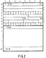
- Figure 2 shows a suitable format of a text packet.
- the text packet shown comprises forty eight bytes of eight bits each.
- the first eight bytes are used for the transfer of parallel control codes.
- the parallel control codes comprise positions codes 21PC and 2PC.
- the position code 21PC indicates the line position on which the corresponding text line is to be displayed on a 21-lines display.
- the position code 2PC indicates the line position of the corresponding text line in the event a 2-line display is used.
- the parallel control codes comprise three control codes which are used for selecting specific text packets from the text packets received. These control codes are indicated as LN (language number), AC (application code) and TC (topic code).
- the code LN indicates the language of the coded text in the corresponding text packet.
- the code AP indicates whether the coded text line comprises information to be displayed on the 1-line display unit 10.
- the code TC indicates the topic to which the corresponding text line relates. Such topics may be e.g. "Album Information", "Performers name” or "The text of the reproduced song”.
- the codes may comprise a character code defining a character of a character set.
- the codes may also comprise serial control codes for the control of the display.
- Figure 9 shows the relation between the code values (hexadecimal) and the corresponding characters. The codes in columns 0x, 1x, 8x and 9x are reserved for the control codes.
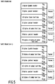
- Figure 4 shows an overview of the serial control codes used in the embodiment described.
- Figure 4 shows two marking codes for marking groups of character codes to be used for displaying a text string.
- These marking codes comprises a start control code S , which is used to indicate the begin of a text string to be displayed on the 1-line display unit, and a control code P , which is used to indicate the end of a text string to be displayed on the 1-line display unit 10.
- Scrolling control codes H0, H1, H2 and H3 with the code values 19, 1A, 1B,and 1C are used for initiating a horizontal scroll with four different scrolling speeds.
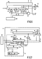
- FIG. 6 shows an embodiment of the sub data processing unit 8.
- the unit 8 comprises a memory in the form of a shift register 60 in which the bytes of the packets received from the input stage 6a are shifted in synchronism with a clock signal cl1 received from a timing control unit 61 of a usual type.
- the unit 8 is further provided with code coincidence detecting circuits 62, 63 and 64.
- the code coincidence detecting circuits 62 and 64 are provided with inputs 66 and 67 for receiving a user selected value for the language selection code LN and topic selection code TC from a user selection entry unit 68 of usual type, e.g. an operation panel with selection keys.
- the code coincidence detecting circuit 63 has an input 72 for receiving a code value corresponding with the code value of AP indicating that the corresponding coded text line comprises information to be displayed on the 1-line display unit 10.
- Inputs 69 , 70 and 71 of the code coincidence detecting circuits 62, 63 and 64 are coupled with parallel outputs of the shift register 60 such that at the moment that the first byte of a received text packet reaches the serial output 65 of the shift register the values of the codes LN, AC and TC are supplied to the code coincidence detecting circuits 62, 63 and 64 respectively.
- the code coincidence detecting circuits 62, 63 and 64 are provided with outputs 73, 74 and 75 for supplying corresponding detection signals to a gate circuit 76 in the events that a coincidences between the code values on the inputs of the circuits 62,63 and 64 are detected.
- the gate circuit 76 is of a usual type that under control of the timing circuit 61 generates a load signal VL during the time that the codes of the coded text lines become available on the output 65 of the shift register 60 after detections of coincidences by all three code coincidence detecting circuits 62, 63 and 64.
- the load signal VL is supplied to an input of a two input AND-gate 96.
- the clock signal cl1 is supplied to the other input of the AND-gate 96, so as to obtain on the output of the AND-gate 96 a clock signal cl2 exclusively during the generation of the load signal VL. Both the clock signal cl2 and the load signal VL are supplied to the display control circuit 9.
- the sub data processing unit 8 operates as follows: In the event that the parallel control codes LN and TC correspond with the user selected values and at the same time the parallel control code AC indicates that the coded text line in the corresponding text packets comprises information to be displayed on the 1-line display unit 10, then the gate circuit 76 starts generating a load signal VL as soon as the first code of the coded text line reaches the output 65 of the shift register 60. As soon as the first parallel control of the next text packet reaches the output 65 the generation of the load signal VL is stopped.
- FIG. 7 shows embodiments of the display control unit 9 and the display unit 10.
- the display control unit 9 comprises a shift register with a number of subsequent byte storage positions which is equal to the number of codes in the coded text lines.
- the shift register 80 shifts the codes received on an input 81 through the register to an output 86 in synchronism with either the clock signal cl1 received from the timing circuit via a OR-gate 95 or a clock signal clcr received from a clock generator 94 with an adjustable oscillating frequency.
- the input 81 is coupled with a two-input multiplex circuit 82.
- a first input 83 is coupled to the output 65 of the shift register 60 of the sub data processing unit 8 via a signal path 84.
- a second input 85 of the multiplex circuit 82 is coupled to the output 86 of the shift register 80.
- An output 97 of the multiplex circuit 82 is coupled to an input 81 of the shift register 80.
- the multiplex circuit 82 is controlled by the load signal VL which is supplied to a control input of the multiplex circuit 82 via a signal line 87.
- the signal VL indicates that a next coded line is available on signal path 84 the codes of this coded text line are fed via the multiplex circuit 82 to the input 81 of the shift register 80.
- the shift register 80 receives the clock signal cl2, so that the codes of the coded text lines, available on the output 65 are shifted into the shift register 80 in synchronism with the clock signal cl2.
- the load signal VL indicates that no codes of a coded text line with information to be displayed on the 1-line display unit 10 are available the code on the output 86 of the shift register 80 are supplied to the input 81 via the multiplex circuit 82.
- the display control unit 9 is further provided with a code detection circuit 87 with an input coupled to the output 97 of the multiplex circuit.
- the code detection circuit 87 is of usual type which detects whether the code on the output 97 of the multiplex circuit 82 coincides with a serial control code or a character code defining a space.
- the detection circuit 87 generates a corresponding output signal when one of the codes mentioned hereinbefore is detected.
- the control signals generated by the detection circuit indicates which type of control code control code has been detected in the event that the detected control code corresponds with a start code S , a pause code P or one of the scroll control codes H0, H1, H2 or H3. These output signals are supplied via signal lines 88 to a gate circuit 89.
- the load signal VL is supplied to the gate circuit 89.
- An other input of the gate circuit 89 is coupled to an output of the user selection entry unit 68 for receiving a user entered scroll command.
- the gate circuit 89 derives control signals for the display unit 10 from the signals received at its inputs.
- the generation of a first control signal LD is started in response to the detection of the first character code not being a space code after the start of a generation of the load signal.
- the generation of the control signal LD is also started in response to the detection a start control code S.
- the generation of the control signal LD is stopped in response to the detection of a pause control code P.
- control signal LD is generated during each detection of a pause control code P in order to achieve that a "space"-character is displayed for each pause code.
- the control signal LD indicates that a character is to be displayed on the next empty character position of a 12-digit displaying element 91 of the display unit 10.
- a second control signal SC is generated in response to a detection of one of the scroll control codes H0, H1, H2 or H3 or in response to a user entered scroll command.
- the control signal Sc indicates that a horizontal scroll of characters corresponding with the subsequent codes outputted by the shift register 80 is requested on the displaying element 91.
- a third control signal RS which is generated in response to the load signal VL, indicates that the displaying element 91 is to be cleared.
- the control signal RS is also generated in response to the first detection of the start control code S in the coded text line. Further the generation of the control signal SC is stopped in response to the load signal VL and the generation of the control signal LD is started in response to the load signal.
- a fourth control signal SS indicates the desired scrolling speed.
- the output 97 of the multiplex circuit 82 is coupled to an input of a decoder unit 92.
- the decoder unit 92 is provided with a shift register for storing the character codes of the characters to be displayed. Further the decoder unit is provided with a decoder for converting the character codes stored in the shift register into control signals for the respective digits of the displaying element 92.
- the decoder is of a usual type which causes the display of a space for serial control codes which does not define a character, such as the pause code P .
- the shift register of the decoder unit 92 is of a usual type that in response to the signal SC causes a shift of the character codes received through the shift register, so as to achieve a horizontal scroll of the characters over the display element 91.
- the shift of the codes through the shift register 80, and the shift register of the decoder unit is controlled by a clock circuit 94.
- the clock circuit 94 In absence of a signal SS the clock circuit 94 the output of a clock signal of the clock circuit is disabled. In the event that a signal SS is present than the output of the clock signal is enabled and a clock signal with a frequency defined by the signal value of the signal SS is supplied directly to the clock input of the shift register of the decoder unit 92 and via OR-gate 95 to the shift register 80.
- the shift register of the decoder unit is brought in a static mode in which characters can be loaded in a memory locations addressed by an address generation circuit 93.
- the address generating circuit is of a usual type that indicates the next empty memory location of the shift register in the decoder unit 92. In the event that all available memory locations are used for storage of codes the loading of newly supplied cods are not stored any more.
- the detection circuit 87 supplies signals to the gate circuit 89 indicating the type of code supplied to input of the decoder circuit 92 of the display unit 10. Since the gate circuit starts to generate the load control signal LD in response to the detection of the first character code not being a space character, the decoder circuit 92 starts loading characters in its shift register from the first memory location onwards, leading space codes and control codes not being one of the control codes shown in figure 4 being ignored for loading.
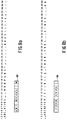
- figure 8a shows a coded text line of forty codes, which are indicated by the characters defined by the codes. A space code is indicated by the symbol "_". The result of the receipt of this coded text line on the 12 digits displaying element 91 is shown within a window 100. The displaying element 91 shows the representations of the character codes on the positions 2-13 in the coded text line. The space on the first position of the coded text line is ignored.
- Figure 8b shows another coded text line.
- This coded text line comprises the pause control code S on position 18 of the coded text line.
- this coded text line is supplied to the display control unit 9 this results in that firstly characters defined by the codes on the positions 3-14 are displayed. However as soon as the start control code S is detected the display is reset and characters defined by the codes on positions 19 - 30 are displayed in window 100.
- Figure 8c shows a coded text line in which the start control code S on position 7 is followed by the pause control code P on position 13 in the coded text line.
- the coded text line further includes a further start control code S on position 19. This result in that the string of characters defined by the character codes between the first start control code S and the pause control code P are displayed. Further the pause control code P causes the display of a space after this character string.
- Figure 8d shows an coded text line which includes the scroll control code H0 on the first position.
- the display unit In response to the detection of the scroll control code H0 the display unit is brought in the horizontal scrolling mode. Further after the coded text line received is loaded completely into the shift register 80, the multiplex circuit 82 is brought in a state in which the output 86 of the shift register 80 is fed to its output 97.
- the clock generator 94 is set to a frequency corresponding to the value indicated by the control code H0. Consequently a horizontal scroll of the character string defined by the coded text line is realized.
- the contents of the twelve digit display element on subsequent clock moments t1,.., t14 is also shown in figure 8d.
- a horizontal scrolling sequence for displaying the text defined by an arbitrary one of the coded text lines received can also be initiated by means of a user entered scroll command, because each coded text line comprising information to be displayed on the 1-line display unit 10 is stored completely in the shift register 80.
- the control signal SC is generated. Consequently the codes of the coded text line available in the shift register 80 are shifted into the decoder unit 92 so as to achieve a horizontal scroll of the corresponding text on the twelve digit display element 91.
- the decoder unit may cause a skip of leading and/or trailing spaces, or it may cause a continuous scroll until the last character is moved out of the display area.
- a Soft Scroll character-column wise
- Character Scroll character by character
- Word Scroll word by word
- Two ways of activating the scrolling may be implemented: automatically or on a user command. Automatic scrolling shall not be activated if a "non-scrolling" code is included in a text line. The scrolling may be controlled automatically. This means that the full text is scrolled without any user interaction. Depending on the design of the hardware, various scrolling methods may be implemented, e.g.
- the scrolling may also be controlled manually. This means the text as marked by the S and P is displayed until a user's scroll command is received.
- various reactions on a user's scroll command may be implemented, e.g.:
- the embodiment of the receiver as described hereinbefore is realized as a so-called hard-wired circuit.
- programm controlled circuits are also possible.
- the invention is not limited to the use of the serial control codes as described.
- Other serial control codes for the control of the representation of character strings on a 1-line display with a limited number of digits are also possible. Further the response of the display control unit on the serial control codes may be different.
- the display unit may be incorporated in a remote controller of the receiver 1.
Abstract
Description
- The invention relates to an information transfer system, comprising a receiver and a transmitter for transferring an information signal to the receiver via a transfer medium, the information signal comprising main data and sub data, the sub data comprising coded text lines having a plurality of character codes, the receiver being provided with a character display unit for displaying characters defined by the character codes in the coded text lines, which display unit has a predetermined number of character display positions.
- The invention further relates to a transmitter, a receiver and a record carrier for use in the system.
- A system as described in the opening paragraph is inter alia known from EP-A-0,325,325. In this patent application a system is described in which the information signal is transferred via a record carrier, e.g. a Compact Disc or a digital audio tape, to an audio player. The player is provided with at least one multi-line display unit for displaying text lines defined by the coded text lines included in the sub data transferred. The number of character positions (digits) of the display unit is sufficient to display a full text line of forty characters. By means of the system additional information related to the main (audio) information reproduced can be displayed.
- The full line display units are less suitable when small sized receivers, such as e.g. portable players and car radios, are used in the system, because in general there is not enough space available for such full line display units. Full line display units are also less suitable to be used on the remote controllers of the receivers. On the other hand it is also desirable that on that type of receivers and remote controllers additional information related to the reproduced main information can be displayed.
- It is on object of the invention to provide means which enables that significant parts of the text information available in the sub data can also be shown on display units on small-sized receivers and remote controllers without the requirement of far-reaching amendments in the sub data format.
- According to the invention this object is achieved for a system described in the openings paragraph which is characterized in that said predetermined number of character positions of the display unit is less than the number of character codes in the coded text lines, in that the coded text lines include control codes, the receiver being provided with display control means for controlling the display of characters corresponding to the character codes included in the coded text line in dependence on the said control codes.
- In the system according the invention the information already available in the coded text lines included in the sub data for displaying on a full line display unit, can also be used for the display on a small sized display unit with a limited number of character positions. This has the advantage that the addition of coded text to the sub data for exclusive use in combination with a 1-line display with a limited number of digits is not required.
- An embodiment of the system is characterized in that the receiver is provided with means for storing received coded text lines into a memory, and in that the control codes comprises horizontal scrolling control codes, the display control means of the receiver being adapted to initiate in response to the horizontal control codes a horizontal scroll of the characters of the coded text line stored in the memory.
- By using a combination of a memory and a scroll function a presentation of the contents of a complete coded text line is possible. A further embodiment of the system is characterized in that the receiver is provided with entry means for manually entering scroll commands, the display control means being adapted to control the scrolling in dependence on the entered scroll commands.
- This embodiment has the advantage that the user himself can initiate a scroll of the coded text line stored in the memory each time when he finds this desirable.
- A further embodiment of the system is characterized in that the display control means are adapted to scroll the characters with a speed dependent on the scrolling control codes or the entered scrolling commands.
- This embodiment enables an adaption of the scrolling speed on specific circumstances.
- An other embodiment of the system is characterized in that the control codes comprises marking codes for marking groups of characters, the display control means being provided with means for selecting the character codes for which corresponding characters are to be displayed on the basis of the marking codes.
- This embodiment enables the presentation of the most significant words of a message on the display.
- Preferably the groups of characters (character strings) to be displayed are placed between a start code and a pause code.
In that event it is preferred to use a system, characterized in that the display control means are adapted to cause a display of a space-type character in response to a pause code, whilst no display of corresponding character is caused for the start codes. - This embodiment enables a very suitable separation on the display unit between character strings which are not subsequent in the message defined by the coded text line.
- A further embodiment of the system is characterized in that the sub information comprise text packets, each text packet comprise a coded text line and additional control codes, a part of the text packets comprises an indicating control code indicating that the corresponding packet comprises a coded text line with text information to be displayed on the display unit with the limited display positions, the receiver is provided with means for preselecting text packets having a indicating control code, and means for exclusively supplying preselected text packets to the display control means.
- By the use of the pre-selection it is prevented that the display control means makes unnecessary searches in coded control lines which does not include characters to be displayed on the 1-line display unit.
- The invention will now be described in more detail, by way of example, with reference to the accompanying drawing, in which
- Figure 1 shows an embodiment of the system according to the invention,
- Figure 2 shows a suitable format of packets for transferring the coded text lines,
- Figure 3 shows an example of parallel control codes included in the packets,
- Figure 4 shows examples of serial control codes which may included in the coded text lines,
- Figure 5 shows, by way of example, how the packets can be incorporated in the sub data of a digital compact cassette,
- Figure 6 shows an embodiment of an sub data processing unit for use in the system according to the invention,
- Figure 7, shows embodiments of a display control unit an display unit for use in the system according to the invention,
- Figures 8a, 8b, 8c and 8d show different coded text lines and character strings displayed in response to the receipt of these coded text lines, and
- Figure 9 shows a possible relation between the character codes and corresponding characters.
- Figure 1 shows, by way of example, an embodiment of a information transfer system according to the invention. The system comprises a
transmitter 1 for transferring an information signal to areceiver 2 via atransfer medium 3. Thetransmitter 1 comprises ausual source 4 of main data, e.g. digital audio information. Thetransmitter 1 further comprises asource 5 of sub data related to the main information. The sub data comprises coded text lines and additional control codes. The main data and sub data are supplied to anoutput stage 6 which transfers the main and sub data in a suitable signal format to thetransfer medium 2. Thereceiver 3 comprises an input stage 6a for receiving the information signal transferred via thetransfer medium 2. The input stage 6a separates the main data and sub information. The main data is supplied to a maindata processing unit 7 of a usual type for processing the main data. The sub data is supplied to a subdata processing unit 8 for processing the sub data. The sub data processing unit supplies coded text lines and corresponding control codes to adisplay control circuit 9 of a 1-line display unit 10 having a limited number of character positions (digits), e.g. a 12-digit display unit. Thedisplay control circuit 9 controls the display of characters defined by character codes included in the coded text lines in dependence on control codes also included in the coded text lines. - The information transfer system can be of type in which the sub data is arranged in packets. In this packets coded text lines can be included. Packets including a coded text line will be indicated as text packets hereinafter. Each coded text line consists of a sequence of a predetermined number of codes. According to the invention the coded text lines comprises character codes defining a character to be displayed and control codes for controlling the display of character strings on a 1-line display with a number of digits which is not sufficient to display a complete text line at once. The control codes included in the coded text line will be indicated as serial control codes hereinafter. The packets may further comprise additional codes not included in the code text line. These control codes will be indicated as parallel control codes hereinafter. A suitable format of the packets is described in detail in EP-A-0,325,325 and EP-A-0,389,689 which documents herewith are incorporated in the description by reference. The transfer medium may be a Compact Disc on which digital main (audio) data is recorded and in which the packets with coded text lines are included in the so-called R to W subcode channels. The transfer medium may also be formed by a so-called Digital Compact Cassette in which main data, in the form of compressed audio information and sub data are recorded on a magnetic tape. The packets including the coded text lines may be included in the sub data recorded on the Digital Compact Cassette. For a more detailed description of a digital compact cassette system reference is made to EP-A 0,436,991 (PHN13209), which document is herewith incorporated in the description by reference. Figure 5 shows, by way of example, how packets can be incorporated in the sub data format of the Digital Compact Cassette-system described in EP-A 0,436,991 (PHN13209).
- The
transfer medium 3 may also be formed by a digital audio broadcast channel via which a digital audio signal and packets including coded text lines are transferred. For a more detailed description of such broadcast system reference is made to EP-A-0,389,689. - Figure 2 shows a suitable format of a text packet. The text packet shown comprises forty eight bytes of eight bits each. The first eight bytes are used for the transfer of parallel control codes. The parallel control codes comprise positions codes 21PC and 2PC. The position code 21PC indicates the line position on which the corresponding text line is to be displayed on a 21-lines display. The position code 2PC indicates the line position of the corresponding text line in the event a 2-line display is used. The parallel control codes comprise three control codes which are used for selecting specific text packets from the text packets received. These control codes are indicated as LN (language number), AC (application code) and TC (topic code). The code LN indicates the language of the coded text in the corresponding text packet. The code AP indicates whether the coded text line comprises information to be displayed on the 1-
line display unit 10. The code TC indicates the topic to which the corresponding text line relates. Such topics may be e.g. "Album Information", "Performers name" or "The text of the reproduced song". - In the text packet forty bytes (bytes 8-47) are used for transferring the codes TLC0,...,TLC40 of the coded text line. The codes may comprise a character code defining a character of a character set. The codes may also comprise serial control codes for the control of the display. Figure 9 shows the relation between the code values (hexadecimal) and the corresponding characters. The codes in
columns line display unit 10. Scrolling control codes H0, H1, H2 and H3 with the code values 19, 1A, 1B,and 1C are used for initiating a horizontal scroll with four different scrolling speeds. - Figure 6 shows an embodiment of the sub
data processing unit 8. Theunit 8 comprises a memory in the form of ashift register 60 in which the bytes of the packets received from the input stage 6a are shifted in synchronism with a clock signal cl1 received from atiming control unit 61 of a usual type. Theunit 8 is further provided with codecoincidence detecting circuits coincidence detecting circuits inputs selection entry unit 68 of usual type, e.g. an operation panel with selection keys. The codecoincidence detecting circuit 63 has aninput 72 for receiving a code value corresponding with the code value of AP indicating that the corresponding coded text line comprises information to be displayed on the 1-line display unit 10.Inputs coincidence detecting circuits shift register 60 such that at the moment that the first byte of a received text packet reaches theserial output 65 of the shift register the values of the codes LN, AC and TC are supplied to the codecoincidence detecting circuits coincidence detecting circuits outputs gate circuit 76 in the events that a coincidences between the code values on the inputs of thecircuits gate circuit 76 is of a usual type that under control of thetiming circuit 61 generates a load signal VL during the time that the codes of the coded text lines become available on theoutput 65 of theshift register 60 after detections of coincidences by all three codecoincidence detecting circuits input AND-gate 96. The clock signal cl1 is supplied to the other input of the AND-gate 96, so as to obtain on the output of the AND-gate 96 a clock signal cl2 exclusively during the generation of the load signal VL. Both the clock signal cl2 and the load signal VL are supplied to thedisplay control circuit 9. - The sub
data processing unit 8 operates as follows: In the event that the parallel control codes LN and TC correspond with the user selected values and at the same time the parallel control code AC indicates that the coded text line in the corresponding text packets comprises information to be displayed on the 1-line display unit 10, then thegate circuit 76 starts generating a load signal VL as soon as the first code of the coded text line reaches theoutput 65 of theshift register 60. As soon as the first parallel control of the next text packet reaches theoutput 65 the generation of the load signal VL is stopped. - Figure 7 shows embodiments of the
display control unit 9 and thedisplay unit 10. Thedisplay control unit 9 comprises a shift register with a number of subsequent byte storage positions which is equal to the number of codes in the coded text lines. Theshift register 80 shifts the codes received on aninput 81 through the register to anoutput 86 in synchronism with either the clock signal cl1 received from the timing circuit via a OR-gate 95 or a clock signal clcr received from aclock generator 94 with an adjustable oscillating frequency. Theinput 81 is coupled with a two-input multiplex circuit 82. Afirst input 83 is coupled to theoutput 65 of theshift register 60 of the subdata processing unit 8 via asignal path 84. Asecond input 85 of themultiplex circuit 82 is coupled to theoutput 86 of theshift register 80. Anoutput 97 of themultiplex circuit 82 is coupled to aninput 81 of theshift register 80. Themultiplex circuit 82 is controlled by the load signal VL which is supplied to a control input of themultiplex circuit 82 via asignal line 87. In the event that the signal VL indicates that a next coded line is available onsignal path 84 the codes of this coded text line are fed via themultiplex circuit 82 to theinput 81 of theshift register 80. At the same time theshift register 80 receives the clock signal cl2, so that the codes of the coded text lines, available on theoutput 65 are shifted into theshift register 80 in synchronism with the clock signal cl2. In the event that the load signal VL indicates that no codes of a coded text line with information to be displayed on the 1-line display unit 10 are available the code on theoutput 86 of theshift register 80 are supplied to theinput 81 via themultiplex circuit 82. - The
display control unit 9 is further provided with acode detection circuit 87 with an input coupled to theoutput 97 of the multiplex circuit. Thecode detection circuit 87 is of usual type which detects whether the code on theoutput 97 of themultiplex circuit 82 coincides with a serial control code or a character code defining a space. Thedetection circuit 87 generates a corresponding output signal when one of the codes mentioned hereinbefore is detected. Further the control signals generated by the detection circuit indicates which type of control code control code has been detected in the event that the detected control code corresponds with a start code S, a pause code P or one of the scroll control codes H0, H1, H2 or H3. These output signals are supplied viasignal lines 88 to agate circuit 89. Further the load signal VL is supplied to thegate circuit 89. An other input of thegate circuit 89 is coupled to an output of the userselection entry unit 68 for receiving a user entered scroll command. Thegate circuit 89 derives control signals for thedisplay unit 10 from the signals received at its inputs. The generation of a first control signal LD is started in response to the detection of the first character code not being a space code after the start of a generation of the load signal. The generation of the control signal LD is also started in response to the detection a start control code S. The generation of the control signal LD is stopped in response to the detection of a pause control code P. Further the control signal LD is generated during each detection of a pause control code P in order to achieve that a "space"-character is displayed for each pause code. The control signal LD indicates that a character is to be displayed on the next empty character position of a 12-digit displaying element 91 of thedisplay unit 10. A second control signal SC is generated in response to a detection of one of the scroll control codes H0, H1, H2 or H3 or in response to a user entered scroll command. The control signal Sc indicates that a horizontal scroll of characters corresponding with the subsequent codes outputted by theshift register 80 is requested on the displaying element 91. A third control signal RS, which is generated in response to the load signal VL, indicates that the displaying element 91 is to be cleared. The control signal RS is also generated in response to the first detection of the start control code S in the coded text line. Further the generation of the control signal SC is stopped in response to the load signal VL and the generation of the control signal LD is started in response to the load signal. A fourth control signal SS indicates the desired scrolling speed. - The
output 97 of themultiplex circuit 82 is coupled to an input of adecoder unit 92. Thedecoder unit 92 is provided with a shift register for storing the character codes of the characters to be displayed. Further the decoder unit is provided with a decoder for converting the character codes stored in the shift register into control signals for the respective digits of the displayingelement 92. The decoder is of a usual type which causes the display of a space for serial control codes which does not define a character, such as the pause code P. The shift register of thedecoder unit 92 is of a usual type that in response to the signal SC causes a shift of the character codes received through the shift register, so as to achieve a horizontal scroll of the characters over the display element 91. The shift of the codes through theshift register 80, and the shift register of the decoder unit is controlled by aclock circuit 94. In absence of a signal SS theclock circuit 94 the output of a clock signal of the clock circuit is disabled. In the event that a signal SS is present than the output of the clock signal is enabled and a clock signal with a frequency defined by the signal value of the signal SS is supplied directly to the clock input of the shift register of thedecoder unit 92 and viaOR-gate 95 to theshift register 80. In absence of the signal SC the shift register of the decoder unit is brought in a static mode in which characters can be loaded in a memory locations addressed by anaddress generation circuit 93. The address generating circuit is of a usual type that indicates the next empty memory location of the shift register in thedecoder unit 92. In the event that all available memory locations are used for storage of codes the loading of newly supplied cods are not stored any more. - The operation of the
display control unit 9 and thedisplay unit 10 will be described hereinafter. In the event that the load signal VL indicates that on theoutput 65 the codes of a next coded text line are available, thenmultiplex circuit 82 is brought in a state in which the codes on theoutput 65 are supplied to the input ofshift register 80. Consequently all codes of the coded text line are shifted into theshift register 80. These codes are also supplied to thedetection circuit 87 and the input thedecoder unit 92. - The
detection circuit 87 supplies signals to thegate circuit 89 indicating the type of code supplied to input of thedecoder circuit 92 of thedisplay unit 10. Since the gate circuit starts to generate the load control signal LD in response to the detection of the first character code not being a space character, thedecoder circuit 92 starts loading characters in its shift register from the first memory location onwards, leading space codes and control codes not being one of the control codes shown in figure 4 being ignored for loading. In order to illustrate this loading process reference is made to figure 8a. This figure shows a coded text line of forty codes, which are indicated by the characters defined by the codes. A space code is indicated by the symbol "_". The result of the receipt of this coded text line on the 12 digits displaying element 91 is shown within awindow 100. The displaying element 91 shows the representations of the character codes on the positions 2-13 in the coded text line. The space on the first position of the coded text line is ignored. - Figure 8b shows another coded text line. This coded text line comprises the pause control code S on
position 18 of the coded text line. When this coded text line is supplied to thedisplay control unit 9 this results in that firstly characters defined by the codes on the positions 3-14 are displayed. However as soon as the start control code S is detected the display is reset and characters defined by the codes on positions 19 - 30 are displayed inwindow 100. - Figure 8c shows a coded text line in which the start control code S on
position 7 is followed by the pause control code P onposition 13 in the coded text line. The coded text line further includes a further start control code S onposition 19. This result in that the string of characters defined by the character codes between the first start control code S and the pause control code P are displayed. Further the pause control code P causes the display of a space after this character string. - As soon as the start control code S on
position 19 is detected the loading of character codes in thedecoder circuit 92 is resumed until all twelve available memory location of the decoder circuit are occupied. - Figure 8d shows an coded text line which includes the scroll control code H0 on the first position. In response to the detection of the scroll control code H0 the display unit is brought in the horizontal scrolling mode. Further after the coded text line received is loaded completely into the
shift register 80, themultiplex circuit 82 is brought in a state in which theoutput 86 of theshift register 80 is fed to itsoutput 97. Theclock generator 94 is set to a frequency corresponding to the value indicated by the control code H0. Consequently a horizontal scroll of the character string defined by the coded text line is realized. The contents of the twelve digit display element on subsequent clock moments t1,.., t14 is also shown in figure 8d. After the scroll of the complete character string defined by the coded text line has been finished a next horizontal scrolling sequence may be initiated again. These repeating scrolling sequence may be continued until the receipt of the next coded text line without scrolling control codes.
A horizontal scrolling sequence for displaying the text defined by an arbitrary one of the coded text lines received can also be initiated by means of a user entered scroll command, because each coded text line comprising information to be displayed on the 1-line display unit 10 is stored completely in theshift register 80. In response to an user entered scroll command the control signal SC is generated. Consequently the codes of the coded text line available in theshift register 80 are shifted into thedecoder unit 92 so as to achieve a horizontal scroll of the corresponding text on the twelve digit display element 91. - It is to be noted that other scrolling methods as described hereinbefore may be implemented.
- A non-limitative overview of suitable scrolling methods will be discussed hereinafter.
- The decoder unit may cause a skip of leading and/or trailing spaces, or it may cause a continuous scroll until the last character is moved out of the display area. A Soft Scroll (character-column wise), Character Scroll (character by character) or Word Scroll (word by word) mode may be used.
- Two ways of activating the scrolling may be implemented: automatically or on a user command. Automatic scrolling shall not be activated if a "non-scrolling" code is included in a text line. The scrolling may be controlled automatically. This means that the full text is scrolled without any user interaction. Depending on the design of the hardware, various scrolling methods may be implemented, e.g.
- the text is scrolled again and again,
- the text is scrolled once, until the last character is moved out of the display area. This method is to be used exclusively for text lines of which the Packed Index equals "00 00h".
- the text is scrolled once, after which the beginning of the text is shown again on the display.
- the text is scrolled once, after which the text marked by the start control code S and the pause control code P controls is shown on the display.
- the text as marked by the control codes S and P is shown first for a (device dependent) period of time, after which one of the above mentioned scrolling methods starts.
- The scrolling may also be controlled manually. This means the text as marked by the S and P is displayed until a user's scroll command is received. Depending on the design of the hardware various reactions on a user's scroll command may be implemented, e.g.:
- the text is scrolled once, after which the end of the text is left on the display. This method is to be used for text lines of which the Packet Index equals "00 00h".
- the text is scrolled once, after which the beginning of the text is shown again on the display.
- the text is scrolled once, after which the text marked by the control codes S and P is shown on the display.
- The embodiment of the receiver as described hereinbefore is realized as a so-called hard-wired circuit. However it will be clear to the skilled man that embodiments realized by means of so-called programm controlled circuits are also possible. Further it is to be noted that the invention is not limited to the use of the serial control codes as described. Other serial control codes for the control of the representation of character strings on a 1-line display with a limited number of digits are also possible. Further the response of the display control unit on the serial control codes may be different.
- Finally it is remarked that the display unit may be incorporated in a remote controller of the
receiver 1.
Claims (28)
- Information transfer system, comprising a receiver and a transmitter for transferring an information signal to the receiver via a transfer medium, the information signal comprising main data and sub data, the sub data comprising coded text lines having a plurality of character codes, the receiver being provided with a character display unit for displaying characters defined by the character codes in the coded text lines, which display unit has a predetermined number of character display positions, characterized in that said predetermined number of character positions of the display unit is less than the number of character codes in the coded text lines, in that the coded text lines include control codes, the receiver being provided with display control means for controlling the display of characters corresponding to the character codes included in the coded text line in dependence on the said control codes.
- Information transfer system as claimed in claim 1, characterized in that the receiver is provided with means for storing received coded text lines into a memory, and in that the control codes comprises horizontal scrolling control codes, the display control means of the receiver being adapted to initiate in response to the horizontal control codes a horizontal scroll of the characters of the coded text line stored in the memory.
- Information transfer system as claimed in claim 2, characterized in that the receiver is provided with entry means for manually entering scroll commands, the display control means being adapted to control the scrolling in dependence on the entered scroll commands.
- Information transfer system as claimed in claim 2 or 3, characterized in that the display control means are adapted to scroll the characters with a speed dependent on the scrolling control codes or the entered scrolling commands.
- Information transfer system as claimed in any one of the preceding claims, characterized in that the control codes comprises marking codes for marking groups of characters, the display control means being provided with means for selecting the character codes for which corresponding characters are to be displayed on the basis of the marking codes.
- Information transfer system as claimed in claim 5, characterized in that the marking codes comprise a start code preceding the marked group of characters, and pause code following the marked group of characters.
- Information transfer system as claimed in claim 6, characterized in that the display control means are adapted to cause a display of a space-type character in response to a pause code, whilst no display of corresponding character is caused for the start codes.
- Information transfer system as claimed in any one of the preceding claims characterized in that the sub information comprise text packets, each text packet comprise a coded text line and additional control codes, a part of the text packets comprises an indicating control code indicating that the corresponding packet comprises a coded text line with text information to be displayed on the display unit with the limited display positions, the receiver is provided with means for preselecting text packets having a indicating control code, and means for exclusively supplying preselected text packets to the display control means.
- Transmitter for use in the system as claimed in any one of the claims 1, the transmitter being provided with means for transferring an information signal to an information signal a transfer medium, the information signal comprising main data and sub data, the sub data comprising coded text lines having a plurality of character codes, characterized in that the coded text lines comprises control codes for controlling the display of characters representing the coded text line on a display unit of which the number character positions is less than the number of characters in the coded text lines.
- Transmitter as claimed 9, characterized in that the control codes comprises horizontal scrolling control codes for the control of a horizontal scrolling of characters representing the coded text line.
- Transmitter as claimed in claim 10, characterized in that the control codes comprise codes for controlling the scrolling speed.
- Transmitter as claimed in any one of the claims 8 to 11, characterized in that the control codes comprises marking codes for marking groups of characters to be displayed on the display unit with a limited number of display positions.
- Transmitter as claimed in claim 12, characterized in that the marking codes comprise a start code preceding the marked group of characters, and pause code following the marked group of characters.
- Transmitter as claimed in any one of the claims 8 to 13, characterized in that the sub information comprise text packets, each text packet comprise a coded text line and additional control codes, a part of the text packets comprises an indicating control code indicating that the corresponding packet comprises a coded text line with text information to be displayed on the display unit with the limited number of display positions.
- Receiver for use in the system as claimed in claim 1, the receiver being provide with means for receiving a information signal from a transfer medium, which information signal comprises main data and sub data, the sub data comprising coded text lines having a plurality of character codes, the receiver being provided with a character display unit for displaying characters corresponding to the character codes in the code text line, characterized in that the display unit has a number of character positions, which number is less than the number of character codes in the coded text lines, the receiver being provided with display control means for controlling the display of characters corresponding in dependence on control codes included in the coded text line.
- Receiver as claimed in claim 15, characterized in that the receiver is provided with means for storing received coded text lines into a memory, and in that the control codes comprises horizontal scrolling control codes, the display control means of the receiver being adapted to initiate in response to the horizontal control codes a horizontal scroll of the characters of the coded text line stored in the memory.
- Receiver as claimed in claim 16, characterized in that the receiver is provided with entry means for manually entering scroll commands, the display control means being adapted to control the scrolling in dependence on the entered scroll commands.
- Receiver as claimed in claim 16 or 17, characterized in that the display control means are adapted to cause a scrolling of the characters with a speed dependent on the scrolling control codes or the entered scrolling commands.
- Receiver as claimed in any one of the claims 15 to 18, characterized in that the display control means are provided with means for exclusively displaying the groups of characters marked by marking codes included in the coded text lines.
- Receiver as claimed in claim 5, characterized in that the display control means are adapted to cause a display of groups of characters between a start code preceding the marked group of characters, and pause code following the marked group of characters.
- Receiver as claimed in claim 20, characterized in that the display control means are adapted to cause a display of a space-type character in response to a pause code, whilst no display of corresponding character is caused for the start codes.
- Receiver as claimed in any one of the claims 15 to 21 for receiving sub information comprising text packets including coded text lines and additional control codes, characterized in that the receiver is provided with means for preselecting text packets having an indicating control code indicating that the corresponding is intend for a display on a display unit with a limited number of character positions, and means for exclusively supplying preselected text packets to the display control means.
- Record carrier for use in the system as claimed in claim 1, on which record carrier an information signal is recorded, which information signal comprises main data and sub data, the sub data comprising coded text lines having a plurality of character codes, characterized in that the coded text lines comprises control codes for controlling the display of characters representing the coded text line on a display unit of which the number character positions is less than the number of characters in the coded text lines.
- Record carrier as claimed 23, characterized in that the control codes comprises horizontal scrolling control codes for the control of a horizontal scrolling of characters representing the coded text line.
- Record carrier as claimed in claim 24, characterized in that the control codes comprise codes for controlling the scrolling speed.
- Record carrier as claimed in any one of the claims 23 to 25, characterized in that the control codes comprises marking codes for marking groups of characters to be displayed on the display unit with a limited number of display positions.
- Record carrier as claimed in claim 26, characterized in that the marking codes comprise a start code preceding the marked group of characters, and pause code following the marked group of characters.
- Record carrier as claimed in any one of the claims 23 to 27, characterized in that the sub information comprise text packets, each text packet comprise a coded text line and additional control codes, a part of the text packets comprises an indicating control code indicating that the corresponding packet comprises a coded text line with text information to be displayed on the display unit with the limited number of display positions.
Priority Applications (1)
| Application Number | Priority Date | Filing Date | Title |
|---|---|---|---|
| EP93200362A EP0561435B1 (en) | 1992-02-19 | 1993-02-11 | Information transfer system, a transmitter, a receiver and a record carrier for use in the system |
Applications Claiming Priority (5)
| Application Number | Priority Date | Filing Date | Title |
|---|---|---|---|
| EP92200487 | 1992-02-19 | ||
| EP92200487 | 1992-02-19 | ||
| EP92200642 | 1992-03-06 | ||
| EP92200642 | 1992-03-06 | ||
| EP93200362A EP0561435B1 (en) | 1992-02-19 | 1993-02-11 | Information transfer system, a transmitter, a receiver and a record carrier for use in the system |
Publications (3)
| Publication Number | Publication Date |
|---|---|
| EP0561435A2 true EP0561435A2 (en) | 1993-09-22 |
| EP0561435A3 EP0561435A3 (en) | 1994-07-13 |
| EP0561435B1 EP0561435B1 (en) | 1999-05-12 |
Family
ID=26131282
Family Applications (1)
| Application Number | Title | Priority Date | Filing Date |
|---|---|---|---|
| EP93200362A Expired - Lifetime EP0561435B1 (en) | 1992-02-19 | 1993-02-11 | Information transfer system, a transmitter, a receiver and a record carrier for use in the system |
Country Status (14)
| Country | Link |
|---|---|
| US (4) | US6480197B1 (en) |
| EP (1) | EP0561435B1 (en) |
| CN (1) | CN1073249C (en) |
| AT (1) | ATE180099T1 (en) |
| CA (1) | CA2089632C (en) |
| CZ (1) | CZ287233B6 (en) |
| DE (1) | DE69324843T2 (en) |
| DK (1) | DK0561435T3 (en) |
| HK (1) | HK1012771A1 (en) |
| HU (1) | HU214126B (en) |
| MX (1) | MX9300810A (en) |
| RU (1) | RU2121164C1 (en) |
| SG (1) | SG48107A1 (en) |
| TW (1) | TW266368B (en) |
Cited By (24)
| Publication number | Priority date | Publication date | Assignee | Title |
|---|---|---|---|---|
| JPH07140963A (en) * | 1993-11-17 | 1995-06-02 | Kokusai Electric Co Ltd | Method and system of displaying scroll |
| WO1996016406A1 (en) * | 1994-11-18 | 1996-05-30 | Philips Electronics N.V. | Information transfer method, information carrier, arrangement for transmitting and arrangement for receiving information |
| US5787090A (en) * | 1994-12-09 | 1998-07-28 | U.S. Phillps Corporation | Audio data system with a first information sub-channel, extraction means for extracting said information, and packetizer means for supplementing said audio in a second information sub-channel, and attacher station and user station for use in such a system |
| FR2776871A1 (en) * | 1998-03-26 | 1999-10-01 | Bosch Gmbh Robert | INFORMATION TRANSMISSION METHOD AND DEVICE |
| EP0953981A2 (en) * | 1998-04-28 | 1999-11-03 | Pioneer Electronic Corporation | Text information reproducing apparatus |
| WO2000005691A1 (en) * | 1998-07-20 | 2000-02-03 | Koninklijke Philips Electronics N.V. | Alphanumeric radio pager with multiline display and system or message selective zoom with horizontal scrolling |
| US6125232A (en) * | 1994-11-24 | 2000-09-26 | Kabushiki Kaisha Toshiba | Large-capacity recording medium, method and apparatus for reproducing data from a large capacity recording medium, and method and apparatus for recording data on a large-capacity recording medium |
| WO2003007291A2 (en) * | 2001-07-13 | 2003-01-23 | Universal Electronics Inc. | System and method for using a hand held device to display information |
| US6788241B2 (en) | 2002-09-25 | 2004-09-07 | Universal Electronics Inc. | System and method for using keystroke data to configure a remote control device |
| US6938101B2 (en) | 2001-01-29 | 2005-08-30 | Universal Electronics Inc. | Hand held device having a browser application |
| US7102688B2 (en) | 2001-01-29 | 2006-09-05 | Universal Electronics Inc. | System and method for using a hand held device to display a readable representation of an audio track |
| US7136709B2 (en) | 2003-11-04 | 2006-11-14 | Universal Electronics Inc. | Home appliance control system and methods in a networked environment |
| US7155305B2 (en) | 2003-11-04 | 2006-12-26 | Universal Electronics Inc. | System and methods for home appliance identification and control in a networked environment |
| US7254777B2 (en) | 2001-12-20 | 2007-08-07 | Universal Electronics Inc. | System and method for controlling the recording functionality of an appliance using a program guide |
| US7610555B2 (en) | 2001-11-20 | 2009-10-27 | Universal Electronics, Inc. | Hand held remote control device having an improved user interface |
| US7831930B2 (en) | 2001-11-20 | 2010-11-09 | Universal Electronics Inc. | System and method for displaying a user interface for a remote control application |
| US7877705B2 (en) | 2001-07-13 | 2011-01-25 | Universal Electronics Inc. | System and methods for interacting with a control environment |
| US8063923B2 (en) | 2001-07-13 | 2011-11-22 | Universal Electronics Inc. | System and method for updating information in an electronic portable device |
| US8863184B2 (en) | 2001-07-13 | 2014-10-14 | Universal Electronics Inc. | System and method for presenting program guide information in an electronic portable device |
| US9137473B2 (en) | 2001-07-13 | 2015-09-15 | Universal Electronics Inc. | System and method for interacting with a program guide displayed on a portable electronic device |
| US9264755B2 (en) | 2001-07-13 | 2016-02-16 | Universal Electronics Inc. | System and method for presenting program guide information in an electronic portable device |
| US9294705B2 (en) | 2008-06-27 | 2016-03-22 | Universal Electronics Inc. | System and method for ubiquitous appliance control |
| US9547979B2 (en) | 2002-04-15 | 2017-01-17 | Universal Elecronics Inc. | System and method for adaptively controlling the recording of program material using a program guide |
| US11812111B2 (en) | 2005-12-20 | 2023-11-07 | Universal Electronics Inc. | System and method for presenting program guide information in an electronic portable device |
Families Citing this family (13)
| Publication number | Priority date | Publication date | Assignee | Title |
|---|---|---|---|---|
| US6292176B1 (en) * | 1996-02-26 | 2001-09-18 | Motorola, Inc. | Method and system for displaying textual information |
| US8042063B1 (en) | 1999-04-19 | 2011-10-18 | Catherine Lin-Hendel | Dynamic array presentation and multiple selection of digitally stored objects and corresponding link tokens for simultaneous presentation |
| CN1196130C (en) | 1999-05-28 | 2005-04-06 | 松下电器产业株式会社 | Semiconductor memory card, playback appts. recording appts. playback method, recording method, and computer-readable storage medium |
| US7542920B1 (en) * | 1999-07-30 | 2009-06-02 | Catherine Lin-Hendel | System for interactive computer-assisted on-line auctions |
| US7574381B1 (en) * | 1999-08-06 | 2009-08-11 | Catherine Lin-Hendel | System and method for constructing and displaying active virtual reality cyber malls, show rooms, galleries, stores, museums, and objects within |
| US7308653B2 (en) * | 2001-01-20 | 2007-12-11 | Catherine Lin-Hendel | Automated scrolling of browser content and automated activation of browser links |
| JP4032355B2 (en) | 2003-03-27 | 2008-01-16 | カシオ計算機株式会社 | Display processing apparatus, display control method, and display processing program |
| US20060015808A1 (en) * | 2004-07-13 | 2006-01-19 | Sony Corporation | Hard disk multimedia player and method |
| US20060012714A1 (en) * | 2004-07-16 | 2006-01-19 | Greenforest Consulting, Inc | Dual-scaler architecture for reducing video processing requirements |
| US20060066567A1 (en) * | 2004-09-29 | 2006-03-30 | Scharenbroch Gregory K | System and method of controlling scrolling text display |
| US20060158357A1 (en) * | 2005-01-19 | 2006-07-20 | Visteon Global Technologies, Inc. | Text compression method for multi-level display |
| RU2452037C2 (en) * | 2010-02-17 | 2012-05-27 | Государственное образовательное учреждение высшего профессионального образования "Башкирский государственный университет", БашГУ | System of data transfer with nanoresistors |
| GB2489100A (en) | 2011-03-16 | 2012-09-19 | Validity Sensors Inc | Wafer-level packaging for a fingerprint sensor |
Citations (4)
| Publication number | Priority date | Publication date | Assignee | Title |
|---|---|---|---|---|
| EP0325325A2 (en) | 1988-01-19 | 1989-07-26 | Koninklijke Philips Electronics N.V. | System for transferring information using an information carrier |
| US4952927A (en) | 1987-08-05 | 1990-08-28 | Motorola, Inc. | Paging receiver with dynamically allocated display rate |
| EP0432056A1 (en) | 1989-11-24 | 1991-06-12 | Nara Technics Co., Ltd | Character information display system of cassette player and a method thereof |
| EP0436991A1 (en) | 1990-01-08 | 1991-07-17 | Koninklijke Philips Electronics N.V. | Digital transmission system, transmitter and receiver to be utilised in the transmission system and record carrier obtained by means of the transmitter in the form of a recording means |
Family Cites Families (9)
| Publication number | Priority date | Publication date | Assignee | Title |
|---|---|---|---|---|
| US4005388A (en) * | 1973-11-21 | 1977-01-25 | Termiflex Corporation | Hand-held interactive terminal |
| JPS58178642A (en) * | 1982-04-13 | 1983-10-19 | Nec Corp | Individual selection and calling receiver with display |
| US5218187A (en) * | 1990-01-18 | 1993-06-08 | Norand Corporation | Hand-held data capture system with interchangeable modules |
| JPS63155257A (en) * | 1986-12-18 | 1988-06-28 | Brother Ind Ltd | Word processor |
| US4833549A (en) * | 1987-01-07 | 1989-05-23 | Casio Computer Co., Ltd. | Digital audio tape record/play-back system for recording/playing back character data together with digital audio data |
| US5280572A (en) * | 1988-06-24 | 1994-01-18 | Time Warner Interactive Group Inc. | Method and apparatus for storing text data in subcode packs |
| US5111426A (en) * | 1989-03-23 | 1992-05-05 | Bergstresser Sr Arthur R | Instructional device and method thereof |
| EP0389689B1 (en) * | 1989-03-28 | 1997-06-04 | POLYGRAM MANUFACTURING & DISTRIBUTION CENTRES GMBH | Method for transmitting a transmission signal and a transmitting device and a receiving device for use in the method |
| DE69121648T2 (en) * | 1990-06-21 | 1997-04-03 | Yamaha Corp | Display device for a compact disc player and a compact disc |
-
1993
- 1993-02-11 DE DE69324843T patent/DE69324843T2/en not_active Expired - Lifetime
- 1993-02-11 AT AT93200362T patent/ATE180099T1/en active
- 1993-02-11 EP EP93200362A patent/EP0561435B1/en not_active Expired - Lifetime
- 1993-02-11 SG SG1996007064A patent/SG48107A1/en unknown
- 1993-02-11 DK DK93200362T patent/DK0561435T3/en active
- 1993-02-16 CA CA002089632A patent/CA2089632C/en not_active Expired - Lifetime
- 1993-02-16 MX MX9300810A patent/MX9300810A/en unknown
- 1993-02-16 CZ CZ1993210A patent/CZ287233B6/en not_active IP Right Cessation
- 1993-02-18 RU RU93004553A patent/RU2121164C1/en active
- 1993-02-18 HU HU9300448A patent/HU214126B/en unknown
- 1993-02-18 CN CN93102170A patent/CN1073249C/en not_active Expired - Lifetime
- 1993-02-22 TW TW082101237A patent/TW266368B/zh not_active IP Right Cessation
-
1995
- 1995-01-04 US US08/368,740 patent/US6480197B1/en not_active Expired - Lifetime
-
1998
- 1998-12-19 HK HK98114087A patent/HK1012771A1/en not_active IP Right Cessation
-
2002
- 2002-10-17 US US10/273,058 patent/US6693636B2/en not_active Expired - Lifetime
-
2003
- 2003-10-14 US US10/685,358 patent/US7696999B1/en not_active Expired - Fee Related
-
2009
- 2009-09-24 US US12/565,806 patent/US8319776B2/en not_active Expired - Fee Related
Patent Citations (4)
| Publication number | Priority date | Publication date | Assignee | Title |
|---|---|---|---|---|
| US4952927A (en) | 1987-08-05 | 1990-08-28 | Motorola, Inc. | Paging receiver with dynamically allocated display rate |
| EP0325325A2 (en) | 1988-01-19 | 1989-07-26 | Koninklijke Philips Electronics N.V. | System for transferring information using an information carrier |
| EP0432056A1 (en) | 1989-11-24 | 1991-06-12 | Nara Technics Co., Ltd | Character information display system of cassette player and a method thereof |
| EP0436991A1 (en) | 1990-01-08 | 1991-07-17 | Koninklijke Philips Electronics N.V. | Digital transmission system, transmitter and receiver to be utilised in the transmission system and record carrier obtained by means of the transmitter in the form of a recording means |
Cited By (46)
| Publication number | Priority date | Publication date | Assignee | Title |
|---|---|---|---|---|
| JPH07140963A (en) * | 1993-11-17 | 1995-06-02 | Kokusai Electric Co Ltd | Method and system of displaying scroll |
| WO1996016406A1 (en) * | 1994-11-18 | 1996-05-30 | Philips Electronics N.V. | Information transfer method, information carrier, arrangement for transmitting and arrangement for receiving information |
| BE1008964A3 (en) * | 1994-11-18 | 1996-10-01 | Philips Electronics Nv | Method for transfer of information, an information carrier, and a device for receiving and a device for sending information. |
| CN1314043C (en) * | 1994-11-18 | 2007-05-02 | 皇家菲利浦电子有限公司 | Information transmission method, device used for transmitting information and device for receiving information |
| US6125232A (en) * | 1994-11-24 | 2000-09-26 | Kabushiki Kaisha Toshiba | Large-capacity recording medium, method and apparatus for reproducing data from a large capacity recording medium, and method and apparatus for recording data on a large-capacity recording medium |
| US5787090A (en) * | 1994-12-09 | 1998-07-28 | U.S. Phillps Corporation | Audio data system with a first information sub-channel, extraction means for extracting said information, and packetizer means for supplementing said audio in a second information sub-channel, and attacher station and user station for use in such a system |
| FR2776871A1 (en) * | 1998-03-26 | 1999-10-01 | Bosch Gmbh Robert | INFORMATION TRANSMISSION METHOD AND DEVICE |
| US6473376B1 (en) | 1998-04-28 | 2002-10-29 | Pioneer Electronic Corporation | Text information reproducing apparatus |
| EP0953981A3 (en) * | 1998-04-28 | 2002-01-02 | Pioneer Electronic Corporation | Text information reproducing apparatus |
| EP0953981A2 (en) * | 1998-04-28 | 1999-11-03 | Pioneer Electronic Corporation | Text information reproducing apparatus |
| WO2000005691A1 (en) * | 1998-07-20 | 2000-02-03 | Koninklijke Philips Electronics N.V. | Alphanumeric radio pager with multiline display and system or message selective zoom with horizontal scrolling |
| US6938101B2 (en) | 2001-01-29 | 2005-08-30 | Universal Electronics Inc. | Hand held device having a browser application |
| US7102688B2 (en) | 2001-01-29 | 2006-09-05 | Universal Electronics Inc. | System and method for using a hand held device to display a readable representation of an audio track |
| US7877705B2 (en) | 2001-07-13 | 2011-01-25 | Universal Electronics Inc. | System and methods for interacting with a control environment |
| US9264755B2 (en) | 2001-07-13 | 2016-02-16 | Universal Electronics Inc. | System and method for presenting program guide information in an electronic portable device |
| US11190852B2 (en) | 2001-07-13 | 2021-11-30 | Universal Electronics Inc. | System and method for presenting program guide information in an electronic portable device |
| US10728626B2 (en) | 2001-07-13 | 2020-07-28 | Universal Electronics Inc. | System and method for presenting program guide information in an electronic portable device |
| WO2003007291A3 (en) * | 2001-07-13 | 2003-06-26 | Universal Electronics Inc | System and method for using a hand held device to display information |
| US10296178B2 (en) | 2001-07-13 | 2019-05-21 | Universal Electronics, Inc. | System and methods for interacting with a control environment |
| US9137473B2 (en) | 2001-07-13 | 2015-09-15 | Universal Electronics Inc. | System and method for interacting with a program guide displayed on a portable electronic device |
| US8997020B2 (en) | 2001-07-13 | 2015-03-31 | Universal Electronics Inc. | System and methods for interacting with a control environment |
| US8863184B2 (en) | 2001-07-13 | 2014-10-14 | Universal Electronics Inc. | System and method for presenting program guide information in an electronic portable device |
| WO2003007291A2 (en) * | 2001-07-13 | 2003-01-23 | Universal Electronics Inc. | System and method for using a hand held device to display information |
| US8063923B2 (en) | 2001-07-13 | 2011-11-22 | Universal Electronics Inc. | System and method for updating information in an electronic portable device |
| US9733804B2 (en) | 2001-11-20 | 2017-08-15 | Universal Electronics Inc. | User interface for a remote control application |
| US8176432B2 (en) | 2001-11-20 | 2012-05-08 | UEI Electronics Inc. | Hand held remote control device having an improved user interface |
| US8473865B2 (en) | 2001-11-20 | 2013-06-25 | Universal Electronics Inc. | User interface for a remote control application |
| US7831930B2 (en) | 2001-11-20 | 2010-11-09 | Universal Electronics Inc. | System and method for displaying a user interface for a remote control application |
| US7610555B2 (en) | 2001-11-20 | 2009-10-27 | Universal Electronics, Inc. | Hand held remote control device having an improved user interface |
| US7895532B2 (en) | 2001-11-20 | 2011-02-22 | Universal Electronics, Inc. | User interface for a remote control application |
| US10168869B2 (en) | 2001-11-20 | 2019-01-01 | Universal Electronics Inc. | System and method for retrieving information while commanding operation of an appliance |
| US10311714B2 (en) | 2001-11-20 | 2019-06-04 | Universal Electronics Inc. | User interface for a remote control application |
| US9310976B2 (en) | 2001-11-20 | 2016-04-12 | Universal Electronics Inc. | User interface for a remote control application |
| US9727213B2 (en) | 2001-11-20 | 2017-08-08 | Universal Electronics Inc. | System and method for retrieving information while commanding operation of an appliance |
| US7254777B2 (en) | 2001-12-20 | 2007-08-07 | Universal Electronics Inc. | System and method for controlling the recording functionality of an appliance using a program guide |
| US9547979B2 (en) | 2002-04-15 | 2017-01-17 | Universal Elecronics Inc. | System and method for adaptively controlling the recording of program material using a program guide |
| US6788241B2 (en) | 2002-09-25 | 2004-09-07 | Universal Electronics Inc. | System and method for using keystroke data to configure a remote control device |
| US7379778B2 (en) | 2003-11-04 | 2008-05-27 | Universal Electronics, Inc. | System and methods for home appliance identification and control in a networked environment |
| US7155305B2 (en) | 2003-11-04 | 2006-12-26 | Universal Electronics Inc. | System and methods for home appliance identification and control in a networked environment |
| US7136709B2 (en) | 2003-11-04 | 2006-11-14 | Universal Electronics Inc. | Home appliance control system and methods in a networked environment |
| US10754517B2 (en) | 2004-01-06 | 2020-08-25 | Universal Electronics Inc. | System and methods for interacting with a control environment |
| US11422683B2 (en) | 2004-01-06 | 2022-08-23 | Universal Electronics Inc. | System and methods for interacting with a control environment |
| US11812111B2 (en) | 2005-12-20 | 2023-11-07 | Universal Electronics Inc. | System and method for presenting program guide information in an electronic portable device |
| US9294705B2 (en) | 2008-06-27 | 2016-03-22 | Universal Electronics Inc. | System and method for ubiquitous appliance control |
| US10638187B2 (en) | 2008-06-27 | 2020-04-28 | Universal Electronics Inc. | System and method for ubiquitous appliance control |
| US11102538B2 (en) | 2008-06-27 | 2021-08-24 | Universal Electronics Inc. | System and method for ubiquitous appliance control |
Also Published As
| Publication number | Publication date |
|---|---|
| US6693636B2 (en) | 2004-02-17 |
| CN1073249C (en) | 2001-10-17 |
| ATE180099T1 (en) | 1999-05-15 |
| DK0561435T3 (en) | 1999-11-08 |
| CN1076568A (en) | 1993-09-22 |
| CA2089632C (en) | 2005-07-26 |
| MX9300810A (en) | 1993-12-01 |
| US7696999B1 (en) | 2010-04-13 |
| CA2089632A1 (en) | 1993-08-20 |
| DE69324843T2 (en) | 1999-11-25 |
| HK1012771A1 (en) | 1999-08-06 |
| TW266368B (en) | 1995-12-21 |
| HU9300448D0 (en) | 1993-05-28 |
| US6480197B1 (en) | 2002-11-12 |
| SG48107A1 (en) | 1998-04-17 |
| US20100014836A1 (en) | 2010-01-21 |
| CZ21093A3 (en) | 1993-10-13 |
| CZ287233B6 (en) | 2000-10-11 |
| EP0561435B1 (en) | 1999-05-12 |
| EP0561435A3 (en) | 1994-07-13 |
| HU214126B (en) | 1997-12-29 |
| HUT63720A (en) | 1993-09-28 |
| US20030043136A1 (en) | 2003-03-06 |
| DE69324843D1 (en) | 1999-06-17 |
| RU2121164C1 (en) | 1998-10-27 |
| US8319776B2 (en) | 2012-11-27 |
Similar Documents
| Publication | Publication Date | Title |
|---|---|---|
| US8319776B2 (en) | Information transfer system, a transmitter, a receiver and a record carrier for use in the system | |
| CA1219334A (en) | Teletext decoder using a common memory | |
| US3648249A (en) | Audio-responsive visual display system incorporating audio and digital information segmentation and coordination | |
| EP0065148B1 (en) | Dictation recording and transcribing machine with variable playback sequence | |
| US4703369A (en) | Video format signal recording and reproducing method | |
| KR890012305A (en) | Information delivery system and information carrier | |
| US5321200A (en) | Data recording system with midi signal channels and reproduction apparatus therefore | |
| US5770811A (en) | Music information recording and reproducing methods and music information reproducing apparatus | |
| JP3767912B2 (en) | Information transmission system | |
| KR100263601B1 (en) | Information transfer system and a transmitter, a receiver and a record carrier for use in the system | |
| CA1225746A (en) | Error correction system for difference set cyclic code in a teletext system | |
| EP0550266B1 (en) | Subcode reading apparatus for a compact disc player | |
| GB2208959A (en) | Magnetic recording and/or reproducing apparatus | |
| JPS6288490A (en) | Teletext signal processing circuit | |
| GB2250666A (en) | Majority decision using reduced number of components | |
| JP3398440B2 (en) | Input channel status data processing method | |
| SU1119019A1 (en) | Driver for loading microprograms | |
| JP2953498B2 (en) | Video and audio playback device with character display function | |
| JP3159702B2 (en) | Method for temporally embedding data words and apparatus for implementing the method | |
| KR970067172A (en) | Broadcast program information display circuit and method | |
| KR930003420B1 (en) | Automatic detectiong apparatus and method for empty space at multi-screen making time | |
| JPS6041098A (en) | Voice editing controller | |
| JPS61198277A (en) | Character display controller | |
| JPS5923379A (en) | Data reading controller for display memory | |
| JPH0124318B2 (en) |
Legal Events
| Date | Code | Title | Description |
|---|---|---|---|
| PUAI | Public reference made under article 153(3) epc to a published international application that has entered the european phase |
Free format text: ORIGINAL CODE: 0009012 |
|
| AK | Designated contracting states |
Kind code of ref document: A2 Designated state(s): AT BE CH DE DK ES FR GB GR IT LI LU MC NL PT SE |
|
| PUAL | Search report despatched |
Free format text: ORIGINAL CODE: 0009013 |
|
| AK | Designated contracting states |
Kind code of ref document: A3 Designated state(s): AT BE CH DE DK ES FR GB GR IT LI LU MC NL PT SE |
|
| RAP1 | Party data changed (applicant data changed or rights of an application transferred) |
Owner name: N.V. PHILIPS' GLOEILAMPENFABRIEKEN Owner name: POLYGRAM GMBH Owner name: POLYGRAM INTERNATIONAL HOLDING B.V. |
|
| 17P | Request for examination filed |
Effective date: 19950113 |
|
| 17Q | First examination report despatched |
Effective date: 19960912 |
|
| RAP1 | Party data changed (applicant data changed or rights of an application transferred) |
Owner name: PHILIPS ELECTRONICS N.V. |
|
| GRAG | Despatch of communication of intention to grant |
Free format text: ORIGINAL CODE: EPIDOS AGRA |
|
| GRAG | Despatch of communication of intention to grant |
Free format text: ORIGINAL CODE: EPIDOS AGRA |
|
| GRAH | Despatch of communication of intention to grant a patent |
Free format text: ORIGINAL CODE: EPIDOS IGRA |
|
| RAP3 | Party data changed (applicant data changed or rights of an application transferred) |
Owner name: KONINKLIJKE PHILIPS ELECTRONICS N.V. |
|
| GRAH | Despatch of communication of intention to grant a patent |
Free format text: ORIGINAL CODE: EPIDOS IGRA |
|
| GRAA | (expected) grant |
Free format text: ORIGINAL CODE: 0009210 |
|
| AK | Designated contracting states |
Kind code of ref document: B1 Designated state(s): AT BE CH DE DK ES FR GB GR IT LI LU MC NL PT SE |
|
| PG25 | Lapsed in a contracting state [announced via postgrant information from national office to epo] |
Ref country code: SE Free format text: THE PATENT HAS BEEN ANNULLED BY A DECISION OF A NATIONAL AUTHORITY Effective date: 19990512 Ref country code: LI Free format text: LAPSE BECAUSE OF FAILURE TO SUBMIT A TRANSLATION OF THE DESCRIPTION OR TO PAY THE FEE WITHIN THE PRESCRIBED TIME-LIMIT Effective date: 19990512 Ref country code: IT Free format text: LAPSE BECAUSE OF FAILURE TO SUBMIT A TRANSLATION OF THE DESCRIPTION OR TO PAY THE FEE WITHIN THE PRE;WARNING: LAPSES OF ITALIAN PATENTS WITH EFFECTIVE DATE BEFORE 2007 MAY HAVE OCCURRED AT ANY TIME BEFORE 2007. THE CORRECT EFFECTIVE DATE MAY BE DIFFERENT FROM THE ONE RECORDED.SCRIBED TIME-LIMIT Effective date: 19990512 Ref country code: GR Free format text: LAPSE BECAUSE OF NON-PAYMENT OF DUE FEES Effective date: 19990512 Ref country code: ES Free format text: THE PATENT HAS BEEN ANNULLED BY A DECISION OF A NATIONAL AUTHORITY Effective date: 19990512 Ref country code: CH Free format text: LAPSE BECAUSE OF FAILURE TO SUBMIT A TRANSLATION OF THE DESCRIPTION OR TO PAY THE FEE WITHIN THE PRESCRIBED TIME-LIMIT Effective date: 19990512 |
|
| REF | Corresponds to: |
Ref document number: 180099 Country of ref document: AT Date of ref document: 19990515 Kind code of ref document: T |
|
| REG | Reference to a national code |
Ref country code: CH Ref legal event code: EP |
|
| REF | Corresponds to: |
Ref document number: 69324843 Country of ref document: DE Date of ref document: 19990617 |
|
| PG25 | Lapsed in a contracting state [announced via postgrant information from national office to epo] |
Ref country code: PT Free format text: LAPSE BECAUSE OF FAILURE TO SUBMIT A TRANSLATION OF THE DESCRIPTION OR TO PAY THE FEE WITHIN THE PRESCRIBED TIME-LIMIT Effective date: 19990812 |
|
| ET | Fr: translation filed | ||
| REG | Reference to a national code |
Ref country code: DK Ref legal event code: T3 |
|
| REG | Reference to a national code |
Ref country code: CH Ref legal event code: PL |
|
| PG25 | Lapsed in a contracting state [announced via postgrant information from national office to epo] |
Ref country code: LU Free format text: LAPSE BECAUSE OF NON-PAYMENT OF DUE FEES Effective date: 20000211 |
|
| PG25 | Lapsed in a contracting state [announced via postgrant information from national office to epo] |
Ref country code: MC Free format text: THE PATENT HAS BEEN ANNULLED BY A DECISION OF A NATIONAL AUTHORITY Effective date: 20000229 |
|
| PLBE | No opposition filed within time limit |
Free format text: ORIGINAL CODE: 0009261 |
|
| STAA | Information on the status of an ep patent application or granted ep patent |
Free format text: STATUS: NO OPPOSITION FILED WITHIN TIME LIMIT |
|
| 26N | No opposition filed | ||
| REG | Reference to a national code |
Ref country code: GB Ref legal event code: IF02 |
|
| PGFP | Annual fee paid to national office [announced via postgrant information from national office to epo] |
Ref country code: FR Payment date: 20120312 Year of fee payment: 20 |
|
| PGFP | Annual fee paid to national office [announced via postgrant information from national office to epo] |
Ref country code: BE Payment date: 20120329 Year of fee payment: 20 Ref country code: DK Payment date: 20120223 Year of fee payment: 20 Ref country code: GB Payment date: 20120229 Year of fee payment: 20 |
|
| PGFP | Annual fee paid to national office [announced via postgrant information from national office to epo] |
Ref country code: NL Payment date: 20120229 Year of fee payment: 20 Ref country code: DE Payment date: 20120430 Year of fee payment: 20 |
|
| REG | Reference to a national code |
Ref country code: DE Ref legal event code: R071 Ref document number: 69324843 Country of ref document: DE |
|
| REG | Reference to a national code |
Ref country code: DE Ref legal event code: R071 Ref document number: 69324843 Country of ref document: DE |
|
| REG | Reference to a national code |
Ref country code: DK Ref legal event code: EUP |
|
| REG | Reference to a national code |
Ref country code: NL Ref legal event code: V4 Effective date: 20130211 |
|
| BE20 | Be: patent expired |
Owner name: KONINKLIJKE *PHILIPS ELECTRONICS N.V. Effective date: 20130211 |
|
| REG | Reference to a national code |
Ref country code: GB Ref legal event code: PE20 Expiry date: 20130210 |
|
| REG | Reference to a national code |
Ref country code: AT Ref legal event code: MK07 Ref document number: 180099 Country of ref document: AT Kind code of ref document: T Effective date: 20130211 |
|
| PGFP | Annual fee paid to national office [announced via postgrant information from national office to epo] |
Ref country code: AT Payment date: 20120223 Year of fee payment: 20 |
|
| PG25 | Lapsed in a contracting state [announced via postgrant information from national office to epo] |
Ref country code: GB Free format text: LAPSE BECAUSE OF EXPIRATION OF PROTECTION Effective date: 20130210 Ref country code: DE Free format text: LAPSE BECAUSE OF EXPIRATION OF PROTECTION Effective date: 20130212 |