EP0560571B1 - Method and apparatus for measuring gas flow using Boyle's law - Google Patents
Method and apparatus for measuring gas flow using Boyle's law Download PDFInfo
- Publication number
- EP0560571B1 EP0560571B1 EP93301768A EP93301768A EP0560571B1 EP 0560571 B1 EP0560571 B1 EP 0560571B1 EP 93301768 A EP93301768 A EP 93301768A EP 93301768 A EP93301768 A EP 93301768A EP 0560571 B1 EP0560571 B1 EP 0560571B1
- Authority
- EP
- European Patent Office
- Prior art keywords
- gas
- inlet
- enclosed volume
- outlet
- accordance
- Prior art date
- Legal status (The legal status is an assumption and is not a legal conclusion. Google has not performed a legal analysis and makes no representation as to the accuracy of the status listed.)
- Expired - Lifetime
Links
Images


Classifications
-
- G—PHYSICS
- G01—MEASURING; TESTING
- G01F—MEASURING VOLUME, VOLUME FLOW, MASS FLOW OR LIQUID LEVEL; METERING BY VOLUME
- G01F1/00—Measuring the volume flow or mass flow of fluid or fluent solid material wherein the fluid passes through a meter in a continuous flow
- G01F1/05—Measuring the volume flow or mass flow of fluid or fluent solid material wherein the fluid passes through a meter in a continuous flow by using mechanical effects
- G01F1/34—Measuring the volume flow or mass flow of fluid or fluent solid material wherein the fluid passes through a meter in a continuous flow by using mechanical effects by measuring pressure or differential pressure
Definitions
- This invention relates to gas flow measuring devices. More specifically, this invention relates to gas flow measuring devices for providing electrical signals representative of gas flow.
- This class of flowmeter is generally termed a positive displacement type flowmeter.
- the gas whose flow is to be measured is periodically accumulated in a separate confining chamber, such as a cylinder with a tight fitting piston, whose volume increases at a rate equal to the flow of the gas (e.g., by displacement of the piston).
- a separate confining chamber such as a cylinder with a tight fitting piston
- the gas flow rate may be computed.
- the soap-film type of positive displacement flowmeter is defined by a smooth-walled cylindrical tube typically fabricated from transparent glass.
- the tube has an inlet end connected to the gas whose flow is to be measured and an outlet end open to ambient. Adjacent the inlet end is an arrangement for introducing a soap film to be swept along the inner volume of the tube by the advancing gas flow.
- Optical sensors arranged at predetermined locations along the tube measure the transit time of the soap film translated along the interior of the tube, and this time value is converted to a gas flow rate using a known algorithm.
- the soap film flowmeter has a dynamic measurement range which is substantially broader than that of other positive displacement flowmeters (typically in the range from about 0.5 to about 500 Ml/min.). Also, this type of flowmeter is relatively inexpensive to manufacture and maintain.
- the major disadvantage of the soap film flowmeter is the requirement that soap film must be periodically generated, introduced into the gas stream and somehow exhausted. Generation of the soap film is typically performed by means of a manually operated bubble generating device, which requires the presence of a human operator and prevents automatic or unattended operation. Also, due to the fact that the wet film is introduced into the gas stream, the stream is contaminated with water vapor, which is unsuitable for many in-line applications involving gasses.
- EP-A-0055836 discloses an apparatus for controlling the volume of the flow of gas.
- a reference volume has an input conduit connected to the source of gas and an output conduit connected to a utilisation device.
- Valves in the input and output conduits are cyclically controlled to permit pressure in the reference volume to reach a high and then to attain a low pressure.
- the reference volume pressure is measured twice during each cycle to provide voltages representative of the high and low pressures.
- Circuit means control the time and duration of the operation of the valves to cause the difference between the high and low pressures to equal a predetermined value.
- US-A-4373549 discloses a gas flowmeter having a transducer with a reservoir.
- the transducer is coupled to the gas flow conduit between the gas supply and the gas outlet.
- Valves are used to alternately interrupt the gas flow along the conduit and divert gas into the transducer and conduct gas from the transducer through to the gas outlet.
- the pressure in the reservoir is measured and the measurements are used to calculate the rate of flow of gas.
- a method of determining the flow rate of a gas along a path having an inlet and an outlet comprising the steps of:
- the present invention provides apparatus for determining the flow rate of a gas along a path having an inlet and an outlet, comprising: an enclosed volume having a gas entrance; a sensor in communication with the gas pressure within said volume for generating an output signal representative of said gas pressure; valve means coupled to said enclosed volume for enabling gas communication between the gas path inlet and said gas entrance when the valve means is in a first position and between said gas entrance and the gas path outlet when the valve means is in a second position; processing means coupled to said sensor for converting the sensor signal to a gas flow rate signal; and control means coupled to said valve means and said processing means for enabling said valve means to alternately couple the gas path inlet to said gas entrance and said gas entrance to the gas path outlet over a fixed measurement cycle so that said enclosed volume is alternately filled, at the end of the filling period being at a first pressure and relieved, at the end of the relief period being at a second pressure, said control means enabling said processing means to generate said gas flow rate signal from the sensor signals representative of the first and second
- Apparatus embodying the invention provides a flowmeter which requires no advance of knowledge of the physical parameters of the gas, introduces no substantial back pressure in the gas flow path, introduces no contamination in the gas path, possesses a wide dynamic range of measurable flow rates, which is compatible with a wide variety of gas flow applications, and is capable of fully automatic operation.
- the gas flow is controlled by a valve positioned in the path between the inlet and the outlet, and the valve is operated to provide a temporary flow path from the inlet to the enclosed volume while blocking the flow path from the volume to the outlet during the first portion of a measurement cycle and to provide a temporary flow path from the volume to the outlet and block the flow path from the inlet to the volume during a subsequent portion of a measurement cycle.
- pressure rise in the blocked path between the inlet and the volume is limited by the accumulator volume in that portion of the path between the inlet and the valve.
- the invention uses the principle of Boyle's law of gasses which states that, at invariant temperature, the product of pressure and volume of a parcel of gas is a constant. Thus, if gas flow is allowed to accumulate in a fixed volume, the pressure of the entrapped gas will rise at rate proportional to the flow rate.
- the flow to be measured is caused to accumulate in a reservoir of known volume for a known time interval.
- the rise in pressure within the vessel is accurately and automatically measured by the sensor and converted to a flow measurement by the processing means, whose accuracy is dependent only upon conformity of the gas composing the measured flow to Boyle's law. Because of the well known universality of this physical law, the accuracy of the invention is thus independent of gas composition. In addition, extremely low back pressure is introduced into the gas flow path, which is significant in many applications. Further, the invention is relatively simple in construction and easy to install and maintain.
- Fig. 1 is a schematic block diagram illustrating the major units comprising a preferred embodiment of the invention.
- a flow inlet 11 is coupled to a first reservoir 12.
- the outlet end of reservoir 12 is coupled by a flow path conduit 13 to a first port 14 of a controllable valve 15.
- a second port 17 of valve 15 is coupled to the gas entrance of a second reservoir 20.
- a third port 18 of valve 15 is coupled to a flow outlet 22.
- Flow outlet 22 may be coupled to any suitable downstream device, such as a gas chromatograph.
- Valve 15 includes a moveable element 19 which provides gas communication among the three ports 14, 17 and 18.
- the reservoir 20 In the actuated position illustrated in Fig. 1, when the valve is actuated by a suitable control signal described below, the reservoir 20 is placed in gas communication with the flow outlet 22 via central port 17, the moveable valve element 19 and outlet port 18.
- the moveable element 19 In the normal unactuated position (not illustrated), the moveable element 19 provides gas communication between inlet port 14 (and thus the flow inlet 11) and reservoir 20 via movable element 19 and central port 17, while blocking gas flow between the reservoir 20 and the outlet 22.
- gas flow is permitted from inlet 11 to reservoir 20 and gas flow from reservoir 20 to outlet 22 is blocked by moveable element 19.
- a pressure sensor 25 having an excitation regulator 26 is arranged to sense the pressure in reservoir 20.
- pressure sensor 25 comprises a Fujikura type Fpm-05PG pressure sensor capable of providing a differential voltage of approximately 17 mV/psig.
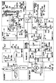
- Pressure sensor 25 is driven by the excitation regulator 26, the circuit for which is illustrated in Fig. 2 in detail.
- Preamplifier 30 is a low-noise differential preamplifier comprising the 2N5087 transistors and associated discrete components shown in detail in Fig. 2.
- Preamplifier 30 is included in the preferred embodiment due to the extreme low amplitude of the electrical pressure signals produced by sensor 25 when measuring low flow rates.
- the desired resolution of 0.01 ml/min. corresponds to a minimum detectable signal of 340 nV. Since this is relatively close to the fundamental limits of circuit noise produced by the known Johnson processes, preamplifier 30 was deemed necessary.
- Preamplifier 30 provides a gain of approximately 24, which is more than adequate to increase the amplitude of the sensor 25 output signal above the noise threshold of a follow-on amplifier 32, which comprises an LMC660 FET amplifier configured in the manner illustrated in Fig. 2.
- Amplifier 32 provides an additional gain of approximately 24, which results in a net sensitivity of 5.71 volts/psi.
- both the preamplifier 30 and the amplifier 32 are AC coupled and therefore insensitive to DC offsets in the output signal generated by sensor 25. As a consequence, only pressure changes are amplified by elements 30 and 32.
- valve 15 is normally biased to the opposite position from that illustrated in Fig. 1 by means of a biasing spring 45.
- Valve 15 is preferably a Clippard type ETO-3H solenoid operated valve available from Clippard Instrument Laboratory, Inc. 7390 Colerain Road, Cincinnati, Ohio.
- the output of the sample and hold unit 35 is coupled to an output unit 45 which buffers and provides a zero reference level for the sample signals output from unit 35.
- the signals output from the unit 45 are coupled to the customary follow-on electronics, such as an analog meter, chart recorder, display or the like.
- a power control unit with optional auto shutoff 50 supplies power from a battery 52 to the various system components.
- the system timing unit 40 comprises a variable period oscillator and decoder comprising the discrete elements illustrated in Fig. 2, which include an amplifier 61, a type 4013 flip flop 62 and a type 4052 multiplexer.
- Three variable resistances 65-67 control the duration of three of the four discrete phases of the four phase measurement cycle defined by four of the multiplexer 63 output terminals. Whenever one of the four phases is active, an enabling voltage of +12 volts DC appears on the corresponding output terminal.
- phase S0 is defined by a 12 volt active level on the output terminal S0
- phase S1 is defined by a 12 volt output on terminal S1, etc.
- Terminal S0 is used to activate a gate 71 in the sample and hold unit 35.
- Terminal S1 is used to initially activate the power amplifier 42 in the valve control unit, and terminal S2 is used to maintain the valve 15 activated and to enable a gate 73 in sample and hold unit 35.
- the duration of the total measurement cycle is selected as 0.4 sec., with the individual phases having a sequence and duration, respectively of 298 ms (S3), 2 ms (S2), 98 ms (S1) and 2 ms (S0).
- Operation of the invention is based upon the principle of Boyle's law of gases which states that at invariant temperature the product of pressure and volume of a parcel of gas is a constant. Thus, if gas flow is allowed to accumulate in a fixed volume, the pressure of the entrapped gas will rise at a rate proportional to the flow rate.
- the flow to be measured is caused to accumulate in reservoir 20 of known volume (56 ml) for a known time interval.
- the pressure rise (which is relatively small compared to the pressure in the gas path in order to avoid substantial back pressure from developing) is accurately and automatically measured by the pressure sensor 25 and follow-on electronic units and converted to a flow measurement whose accuracy is dependent only upon conformity of the gas composing the measured flow to Boyle's law. Because of the well known universality of this physical law, the accuracy of the flow meter is thus independent of gas composition.
- Flow measure proceeds in a four phase cycle which totals about 0.4 sec.
- phase 1 (indicated by state S3 of the system timing unit 40)
- valve 15 is in the de-energized state (the alternate state from that illustrated in Fig. 1).
- the exhaust port 18 is closed and the inlet port 14 is in gas communication with central port 17, which permits the gas flowing into the inlet path 11 to pass through reservoir 12, gas path section 13, inlet port 14, central port 17 and into reservoir 20.
- the pressure in reservoir 20 rises to a maximum value.
- pressure sensor 25 In response to applied pressure, pressure sensor 25 generates a differential voltage of approximately 17 mV/psig. Variations in this signal, which correspond to changes in pressure in reservoir 20, are amplified by low-noise differential preamplifier 30.
- the amplified signals output from preamplifier 30 are in turn amplified by amplifier 32 and presented to the sample input of sample and hold unit 35.
- valve 15 is energized by the application of the S2 signal from system timing unit 40 to the base of the power transistor within amplifier 42. Since the valve 15 has a finite actuation delay of 5 ms, no mechanical motion occurs at this point. However, during the period of maximum pressure within reservoir 20, an analog switch 73 (see Fig. 2) in sample and hold unit 35 is closed connecting the right handplate of a sample and hold capacitor 75 to the upper terminal of a resistor 76. This action serves to capture the maximum pressure reference signal.
- valve 15 achieves the activated state illustrated in Fig. 1 in which reservoir 20 is gas coupled to the flow outlet 22 via valve ports 17 and 18, and in which valve inlet port 14 is closed thereby blocking the inlet path to reservoir 20.
- reservoir 12 serves as an accumulator to limit the amount of pressure rise in the inlet line (and thus the back pressure experienced by the gas source).
- pressure sensor 25 As the pressure drops in reservoir 20 a corresponding signal change is generated by pressure sensor 25.
- This signal change is amplified by preamplifier 30 and amplifier 32, which causes a positive voltage excursion of the right hand plate of sample and hold capacitor 75. The ultimate magnitude of this excursion is directly related to the gas flow rate in the following way.
- valve 15 is deenergized. Due to the mechanical delay, immediate closure of the valve 15 to the unactivated opposite state from that depicted in Fig. 1 is prevented.
- the minimum pressure in reservoir 20 at this point produces the peak positive excursion of the signal produced by the sample and hold capacitor 75.
- This value is sampled via analog switch 71, which is closed by the S0 signal, and the sampled value is momentarily stored on an output hold capacitor 77.
- the voltage on capacitor 77 is buffered by a unity gain amplifier 79 and applied to the positive output terminal 80 as the final flow signal.
- Zero offset adjustment of the final flow signal is provided by a potentiometer 82 connected to the negative output terminal 83.
- Exact calibration of the flow/voltage scale factor is accomplished by adjustment of the potentiometer 67, which is used to adjust the duration of phase 1 of the cycle and, thus, the duration of the gas accumulation in reservoir 20.
- Potentiometers 65 and 66 are used to provide fine adjustment of the duration of phase 2 and phase 4 of the total measurement cycle.
- Excitation regulator unit 26 provides accurately regulated current required by the sensor 25 in order to sense the response of this unit to changes in pressure in reservoir 20.
- Sensor 25 operates on the principle of allowing the pressure to be sensed to impinge upon a silicon diaphragm, and the resulting strain is sensed by the piezo resistive strain gauge bridge shown in Fig. 2.
- Excitation regulator unit 26 includes an amplifier 91, a type LM385 diode 93 which provides a voltage reference, and the discrete components illustrated in Fig. 2, which together regulate a pressure sensor excitation current of 1.25 mA.
- Voltage reference diode 93 also is used to support the zero offset function afforded by potentiometer 82 and serves to provide stability for the system timing unit 40.
- the optional auto-off circuit shown in Fig. 2 provides an automatic power management function for applying power to the sensor 25 upon actuation of a push button switch. Power is automatically removed when at least 2 min. have elapsed since the last actuation of switch 101, and the indicated flow is less than 1.5 ml per min.
- Flow meters constructed according to the teachings of the invention provide a relatively higher accuracy than the inexpensive soap film type of flow meter and are relatively simple and clean to install and operate. Further, the system is capable of fully automatic operation, which can be a substantial disadvantage to the soap film type of flow meter in many applications.
- the invention provides a flow meter with a relatively wide dynamic range of flow measurement, is one which is insensitive to variation in gas stream composition (so long as the gas obeys Boyle's law), and one which imposes very low back pressure loadings on the gas flow source. Flow meters constructed according to the invention can be especially useful in the measurement of carrier gas flow in the chemical analysis technique of gas chromatography.
- FIG. 3 An alternate embodiment of the invention having an analog to digital converter and LCD display is illustrated in logic circuit form in Fig. 3.
Description
- This invention relates to gas flow measuring devices. More specifically, this invention relates to gas flow measuring devices for providing electrical signals representative of gas flow.
- Many techniques exist in the prior art for the electronic measurement of gas flow. Typically, such techniques require prior knowledge of the physical properties of the gas to be measured so that the measuring instrument can be calibrated. Typical examples of such physical properties are the specific heat capacity, density, viscosity, and thermal conductivity of the gas. Many of these physical parameters are themselves dependent upon the composition of the gas. For applications in which the gas composition is unknown or variable in an unpredictable way, such techniques are both inaccurate and unsuitable.
- Additional disadvantages inherent in many prior art techniques include limitations in the range of flow rates over which accurate measurements can be reliably made, sometimes termed the "turn-down ratio", and the generation of unacceptable back pressure in the gas path when the flow meter is connected and operational.
- In an attempt to overcome the above-noted shortcomings of the prior art, flow meters have been developed which are less sensitive to gas physical parameters. This class of flowmeter is generally termed a positive displacement type flowmeter. In a positive displacement flowmeter, the gas whose flow is to be measured is periodically accumulated in a separate confining chamber, such as a cylinder with a tight fitting piston, whose volume increases at a rate equal to the flow of the gas (e.g., by displacement of the piston). By measuring the rate of increase of the confined volume (e.g., by generating a signal representative of the amount of displacement of the piston), the gas flow rate may be computed. While specific flowmeter details (such as the manner of defining the confined volume and the technique for transducing the rate of volume change) differ depending on the style and application of a given positive displacement flowmeter, all such flowmeters possess the desirable property of reasonable accuracy in the gas flow measurement independent of the physical parameters of the gas being measured. However, a severe disadvantage in known positive displacement flowmeters is the disturbance in the gas flow caused by the necessity of displacing the movable surface of the confining chamber in order to generate the measurement signal. This introduces back pressure characteristics which render such flowmeters unsuitable for use in any application sensitive to the periodic introduction of gas flow back pressure.
- One positive displacement type gas flowmeter which has been developed to reduce the adverse back pressure effect is the soap-film type of positive displacement flowmeter. In this type of flowmeter, the confined volume is defined by a smooth-walled cylindrical tube typically fabricated from transparent glass. The tube has an inlet end connected to the gas whose flow is to be measured and an outlet end open to ambient. Adjacent the inlet end is an arrangement for introducing a soap film to be swept along the inner volume of the tube by the advancing gas flow. Optical sensors arranged at predetermined locations along the tube measure the transit time of the soap film translated along the interior of the tube, and this time value is converted to a gas flow rate using a known algorithm. Due to the fact that only the relatively small forces of viscosity and surface tension effects oppose the motion of the soap film and thus the flow of the gas stream, the back pressures generated by this type of flowmeter are generally sufficiently low to be acceptable. In addition, the soap film flowmeter has a dynamic measurement range which is substantially broader than that of other positive displacement flowmeters (typically in the range from about 0.5 to about 500 Ml/min.). Also, this type of flowmeter is relatively inexpensive to manufacture and maintain. The major disadvantage of the soap film flowmeter is the requirement that soap film must be periodically generated, introduced into the gas stream and somehow exhausted. Generation of the soap film is typically performed by means of a manually operated bubble generating device, which requires the presence of a human operator and prevents automatic or unattended operation. Also, due to the fact that the wet film is introduced into the gas stream, the stream is contaminated with water vapor, which is unsuitable for many in-line applications involving gasses.
- EP-A-0055836 discloses an apparatus for controlling the volume of the flow of gas. A reference volume has an input conduit connected to the source of gas and an output conduit connected to a utilisation device. Valves in the input and output conduits are cyclically controlled to permit pressure in the reference volume to reach a high and then to attain a low pressure. The reference volume pressure is measured twice during each cycle to provide voltages representative of the high and low pressures. Circuit means control the time and duration of the operation of the valves to cause the difference between the high and low pressures to equal a predetermined value.
- US-A-4373549 discloses a gas flowmeter having a transducer with a reservoir. The transducer is coupled to the gas flow conduit between the gas supply and the gas outlet. Valves are used to alternately interrupt the gas flow along the conduit and divert gas into the transducer and conduct gas from the transducer through to the gas outlet. The pressure in the reservoir is measured and the measurements are used to calculate the rate of flow of gas.
- According to a first aspect of the invention, there is provided a method of determining the flow rate of a gas along a path having an inlet and an outlet, said method comprising the steps of:
- (a) directing the gas from the inlet into an enclosed volume for a known time interval, at the end of which the gas pressure in the enclosed volume has a first value;
- (b) blocking the flow of gas from the inlet to the enclosed volume and relieving the gas pressure from the enclosed volume through the outlet for a known time interval, at the end of which the gas pressure in the volume has a second value;
- (c) generating a signal representative of the change in gas pressure in the enclosed volume between said first and said second values; and
- (d) determining the gas flow rate from the signal generated in step (c);
- In a second aspect, the present invention provides apparatus for determining the flow rate of a gas along a path having an inlet and an outlet, comprising: an enclosed volume having a gas entrance; a sensor in communication with the gas pressure within said volume for generating an output signal representative of said gas pressure; valve means coupled to said enclosed volume for enabling gas communication between the gas path inlet and said gas entrance when the valve means is in a first position and between said gas entrance and the gas path outlet when the valve means is in a second position; processing means coupled to said sensor for converting the sensor signal to a gas flow rate signal; and control means coupled to said valve means and said processing means for enabling said valve means to alternately couple the gas path inlet to said gas entrance and said gas entrance to the gas path outlet over a fixed measurement cycle so that said enclosed volume is alternately filled, at the end of the filling period being at a first pressure and relieved, at the end of the relief period being at a second pressure, said control means enabling said processing means to generate said gas flow rate signal from the sensor signals representative of the first and second gas pressure values during the measurement cycle; characterised by an accumulator means arranged between said gas path inlet and said gas entrance so that gas passing from said inlet to said gas entrance passes via said accumulator volume.
- Apparatus embodying the invention provides a flowmeter which requires no advance of knowledge of the physical parameters of the gas, introduces no substantial back pressure in the gas flow path, introduces no contamination in the gas path, possesses a wide dynamic range of measurable flow rates, which is compatible with a wide variety of gas flow applications, and is capable of fully automatic operation.
- In an embodiment, the gas flow is controlled by a valve positioned in the path between the inlet and the outlet, and the valve is operated to provide a temporary flow path from the inlet to the enclosed volume while blocking the flow path from the volume to the outlet during the first portion of a measurement cycle and to provide a temporary flow path from the volume to the outlet and block the flow path from the inlet to the volume during a subsequent portion of a measurement cycle. During the subsequent portion of the measurement cycle, pressure rise in the blocked path between the inlet and the volume is limited by the accumulator volume in that portion of the path between the inlet and the valve.
- The invention uses the principle of Boyle's law of gasses which states that, at invariant temperature, the product of pressure and volume of a parcel of gas is a constant. Thus, if gas flow is allowed to accumulate in a fixed volume, the pressure of the entrapped gas will rise at rate proportional to the flow rate. In the invention, the flow to be measured is caused to accumulate in a reservoir of known volume for a known time interval. The rise in pressure within the vessel is accurately and automatically measured by the sensor and converted to a flow measurement by the processing means, whose accuracy is dependent only upon conformity of the gas composing the measured flow to Boyle's law. Because of the well known universality of this physical law, the accuracy of the invention is thus independent of gas composition. In addition, extremely low back pressure is introduced into the gas flow path, which is significant in many applications. Further, the invention is relatively simple in construction and easy to install and maintain.
- For a fuller understanding of the nature and advantages of the invention, reference should be had to the ensuing detailed description taken in conjunction with the accompanying drawings.
- Fig. 1 is a schematic block diagram illustrating a preferred embodiment of the invention;
- Fig. 2 is a detailed schematic of the embodiment of Fig. 1; and
- Fig. 3 is a detailed schematic of an alternate embodiment of the invention.
- Turning now to the drawings, Fig. 1 is a schematic block diagram illustrating the major units comprising a preferred embodiment of the invention. As seen in this Fig., a
flow inlet 11 is coupled to afirst reservoir 12. The outlet end ofreservoir 12 is coupled by aflow path conduit 13 to afirst port 14 of acontrollable valve 15. Asecond port 17 ofvalve 15 is coupled to the gas entrance of asecond reservoir 20. Athird port 18 ofvalve 15 is coupled to aflow outlet 22.Flow outlet 22 may be coupled to any suitable downstream device, such as a gas chromatograph. - Valve 15 includes a
moveable element 19 which provides gas communication among the threeports reservoir 20 is placed in gas communication with theflow outlet 22 viacentral port 17, themoveable valve element 19 andoutlet port 18. In the normal unactuated position (not illustrated), themoveable element 19 provides gas communication between inlet port 14 (and thus the flow inlet 11) andreservoir 20 viamovable element 19 andcentral port 17, while blocking gas flow between thereservoir 20 and theoutlet 22. Thus, in the normal or rest position gas flow is permitted frominlet 11 toreservoir 20 and gas flow fromreservoir 20 tooutlet 22 is blocked bymoveable element 19. - A
pressure sensor 25 having anexcitation regulator 26 is arranged to sense the pressure inreservoir 20. In the preferred embodiment,pressure sensor 25 comprises a Fujikura type Fpm-05PG pressure sensor capable of providing a differential voltage of approximately 17 mV/psig.Pressure sensor 25 is driven by theexcitation regulator 26, the circuit for which is illustrated in Fig. 2 in detail. - The output of
pressure sensor 25 is coupled to apreamplifier 30 for initial amplification of the electrical output signal from thesensor 25.Preamplifier 30 is a low-noise differential preamplifier comprising the 2N5087 transistors and associated discrete components shown in detail in Fig. 2.Preamplifier 30 is included in the preferred embodiment due to the extreme low amplitude of the electrical pressure signals produced bysensor 25 when measuring low flow rates. In the preferred embodiment, the desired resolution of 0.01 ml/min. corresponds to a minimum detectable signal of 340 nV. Since this is relatively close to the fundamental limits of circuit noise produced by the known Johnson processes,preamplifier 30 was deemed necessary.Preamplifier 30 provides a gain of approximately 24, which is more than adequate to increase the amplitude of thesensor 25 output signal above the noise threshold of a follow-onamplifier 32, which comprises an LMC660 FET amplifier configured in the manner illustrated in Fig. 2.Amplifier 32 provides an additional gain of approximately 24, which results in a net sensitivity of 5.71 volts/psi. In the preferred embodiment, both thepreamplifier 30 and theamplifier 32 are AC coupled and therefore insensitive to DC offsets in the output signal generated bysensor 25. As a consequence, only pressure changes are amplified byelements - The output of
amplifier 32 is coupled to the sample input of a sample and holdunit 35. The timing of the sample acquisition is under control of asystem timing unit 40, which also controls the operation ofmovable element 19 ofvalve 15 via apower amplifier 42 which drives a solenoid coil 44. It should be noted thatvalve 15 is normally biased to the opposite position from that illustrated in Fig. 1 by means of a biasingspring 45.Valve 15 is preferably a Clippard type ETO-3H solenoid operated valve available from Clippard Instrument Laboratory, Inc. 7390 Colerain Road, Cincinnati, Ohio. - The output of the sample and hold
unit 35 is coupled to anoutput unit 45 which buffers and provides a zero reference level for the sample signals output fromunit 35. The signals output from theunit 45 are coupled to the customary follow-on electronics, such as an analog meter, chart recorder, display or the like. A power control unit withoptional auto shutoff 50 supplies power from abattery 52 to the various system components. - The
system timing unit 40 comprises a variable period oscillator and decoder comprising the discrete elements illustrated in Fig. 2, which include anamplifier 61, atype 4013flip flop 62 and atype 4052 multiplexer. Three variable resistances 65-67 control the duration of three of the four discrete phases of the four phase measurement cycle defined by four of themultiplexer 63 output terminals. Whenever one of the four phases is active, an enabling voltage of +12 volts DC appears on the corresponding output terminal. Thus, phase S0 is defined by a 12 volt active level on the output terminal S0, phase S1 is defined by a 12 volt output on terminal S1, etc. Terminal S0 is used to activate a gate 71 in the sample and holdunit 35. Terminal S1 is used to initially activate thepower amplifier 42 in the valve control unit, and terminal S2 is used to maintain thevalve 15 activated and to enable agate 73 in sample and holdunit 35. In the preferred embodiment, the duration of the total measurement cycle is selected as 0.4 sec., with the individual phases having a sequence and duration, respectively of 298 ms (S3), 2 ms (S2), 98 ms (S1) and 2 ms (S0). - Operation of the invention is based upon the principle of Boyle's law of gases which states that at invariant temperature the product of pressure and volume of a parcel of gas is a constant. Thus, if gas flow is allowed to accumulate in a fixed volume, the pressure of the entrapped gas will rise at a rate proportional to the flow rate.
- In the flow meter according to the invention, the flow to be measured is caused to accumulate in
reservoir 20 of known volume (56 ml) for a known time interval. The pressure rise (which is relatively small compared to the pressure in the gas path in order to avoid substantial back pressure from developing) is accurately and automatically measured by thepressure sensor 25 and follow-on electronic units and converted to a flow measurement whose accuracy is dependent only upon conformity of the gas composing the measured flow to Boyle's law. Because of the well known universality of this physical law, the accuracy of the flow meter is thus independent of gas composition. - Flow measure proceeds in a four phase cycle which totals about 0.4 sec. During phase 1 (indicated by state S3 of the system timing unit 40),
valve 15 is in the de-energized state (the alternate state from that illustrated in Fig. 1). In this state, theexhaust port 18 is closed and theinlet port 14 is in gas communication withcentral port 17, which permits the gas flowing into theinlet path 11 to pass throughreservoir 12,gas path section 13,inlet port 14,central port 17 and intoreservoir 20. During this phase, the pressure inreservoir 20 rises to a maximum value. In response to applied pressure,pressure sensor 25 generates a differential voltage of approximately 17 mV/psig. Variations in this signal, which correspond to changes in pressure inreservoir 20, are amplified by low-noise differential preamplifier 30. The amplified signals output frompreamplifier 30 are in turn amplified byamplifier 32 and presented to the sample input of sample and holdunit 35. During phase 2 (indicated by state S2 of the system timing unit 40),valve 15 is energized by the application of the S2 signal fromsystem timing unit 40 to the base of the power transistor withinamplifier 42. Since thevalve 15 has a finite actuation delay of 5 ms, no mechanical motion occurs at this point. However, during the period of maximum pressure withinreservoir 20, an analog switch 73 (see Fig. 2) in sample and holdunit 35 is closed connecting the right handplate of a sample and holdcapacitor 75 to the upper terminal of aresistor 76. This action serves to capture the maximum pressure reference signal. - After the 5 ms actuation delay, during phase 3 (indicated by state S1 of the system timing unit 40)
valve 15 achieves the activated state illustrated in Fig. 1 in whichreservoir 20 is gas coupled to theflow outlet 22 viavalve ports valve inlet port 14 is closed thereby blocking the inlet path toreservoir 20. During this phase,reservoir 12 serves as an accumulator to limit the amount of pressure rise in the inlet line (and thus the back pressure experienced by the gas source). In addition, as the pressure drops in reservoir 20 a corresponding signal change is generated bypressure sensor 25. This signal change is amplified bypreamplifier 30 andamplifier 32, which causes a positive voltage excursion of the right hand plate of sample and holdcapacitor 75. The ultimate magnitude of this excursion is directly related to the gas flow rate in the following way. - At equilibrium, the gas vented during this phase must be all the gas accumulated during the previous 400 ms cycle (since the gas has no other outlet). That quantity of gas is therefore the product of the flow rate F times the length of the measurement (0.00667 min.). The change in pressure in
reservoir 20 produced by the venting duringphase 3 of the cycle is therefore (by Boyle's law) given by the following expression:
reservoir 20.
The pressure/voltage gain ofpressure sensor 25 andamplifiers 
- During the last phase of the measurement cycle (indicated by state S0 of the system timing unit 40), which has a duration of 2 ms,
valve 15 is deenergized. Due to the mechanical delay, immediate closure of thevalve 15 to the unactivated opposite state from that depicted in Fig. 1 is prevented. The minimum pressure inreservoir 20 at this point produces the peak positive excursion of the signal produced by the sample and holdcapacitor 75. This value is sampled via analog switch 71, which is closed by the S0 signal, and the sampled value is momentarily stored on an output hold capacitor 77. The voltage on capacitor 77 is buffered by aunity gain amplifier 79 and applied to thepositive output terminal 80 as the final flow signal. - Zero offset adjustment of the final flow signal is provided by a potentiometer 82 connected to the negative output terminal 83. Exact calibration of the flow/voltage scale factor is accomplished by adjustment of the
potentiometer 67, which is used to adjust the duration ofphase 1 of the cycle and, thus, the duration of the gas accumulation inreservoir 20. Potentiometers 65 and 66 are used to provide fine adjustment of the duration ofphase 2 andphase 4 of the total measurement cycle. -
Excitation regulator unit 26 provides accurately regulated current required by thesensor 25 in order to sense the response of this unit to changes in pressure inreservoir 20.Sensor 25 operates on the principle of allowing the pressure to be sensed to impinge upon a silicon diaphragm, and the resulting strain is sensed by the piezo resistive strain gauge bridge shown in Fig. 2.Excitation regulator unit 26 includes anamplifier 91, atype LM385 diode 93 which provides a voltage reference, and the discrete components illustrated in Fig. 2, which together regulate a pressure sensor excitation current of 1.25 mA.Voltage reference diode 93 also is used to support the zero offset function afforded by potentiometer 82 and serves to provide stability for thesystem timing unit 40. - The optional auto-off circuit shown in Fig. 2 provides an automatic power management function for applying power to the
sensor 25 upon actuation of a push button switch. Power is automatically removed when at least 2 min. have elapsed since the last actuation ofswitch 101, and the indicated flow is less than 1.5 ml per min. - Flow meters constructed according to the teachings of the invention provide a relatively higher accuracy than the inexpensive soap film type of flow meter and are relatively simple and clean to install and operate. Further, the system is capable of fully automatic operation, which can be a substantial disadvantage to the soap film type of flow meter in many applications. In addition, the invention provides a flow meter with a relatively wide dynamic range of flow measurement, is one which is insensitive to variation in gas stream composition (so long as the gas obeys Boyle's law), and one which imposes very low back pressure loadings on the gas flow source. Flow meters constructed according to the invention can be especially useful in the measurement of carrier gas flow in the chemical analysis technique of gas chromatography.
- An alternate embodiment of the invention having an analog to digital converter and LCD display is illustrated in logic circuit form in Fig. 3.
- While the above provides a full and complete disclosure of the preferred embodiments of the invention, various modifications, alternate constructions and equivalents may be employed without departing from the spirit and scope of the invention. For example, while specific circuit elements have been described above, other specific elements may be employed, depending on the requirements of a particular application. In addition, other sensors and valves may be found suitable for particular applications. Therefore, the above description and illustrations should not be construed as limiting the scope of the invention which is defined by the appended claims.
Claims (15)
- A method of determining the flow rate of a gas along a path having an inlet (11) and an outlet (22), said method comprising the steps of:(a) directing the gas from the inlet (11) into an enclosed volume (20) for a known time interval, at the end of which the gas pressure in the enclosed volume has a first value;(b) blocking the flow of gas from the inlet (11) to the enclosed volume (20) and relieving the gas pressure from the enclosed volume (20) through the outlet (22) for a known time interval, at the end of which the gas pressure in the volume has a second value;(c) generating a signal representative of the change in gas pressure in the enclosed volume (20) between said first and said second values; and(d) determining the gas flow rate from the signal generated in step (c);characterised by providing an accumulator volume (12) arranged so that gas directed from said inlet (11) to said enclosed volume (20), passes through said accumulator volume (12).
- A method in accordance with claim 1 wherein said step (a) of directing is preceded by the step of providing a controllable valve (15) in the path between the inlet (11) and the outlet (22).
- A method in accordance with claim 1 or 2 wherein said step (a) of directing includes the steps of operating the valve (15) to provide a temporary flow path from the inlet (11) to the enclosed volume (20) and blocking the flow path from the enclosed volume to the outlet (22).
- A method in accordance with any of the preceding claims wherein said step (b) of blocking includes the step of operating the valve (15) to provide a temporary flow path from the enclosed volume (20) to the outlet (22) and blocking the flow path from the inlet (11) to the enclosed volume (20).
- A method in accordance with any of the preceding claims wherein said step (c) of generating includes the steps of generating a signal representative of the gas pressure in the enclosed volume and sampling the maximum and minimum values of the signal.
- A method in accordance with any of the preceding claims wherein said step (d) of determining includes the step of applying the signal generated in step (c) to a display device.
- Apparatus for determining the flow rate of a gas along a path having an inlet (11) and an outlet (22), comprising:an enclosed volume (20) having a gas entrance (17);a sensor (25) in communication with the gas pressure within said volume (20) for generating an output signal representative of said gas pressure;valve means (15) coupled to said enclosed volume (20) for enabling gas communication between the gas path inlet (11) and said gas entrance (17) when the valve means (15) is in a first position and between said gas entrance and the gas path outlet (22) when the valve means (15) is in a second position;processing means (30, 32, 35, 40, 45) coupled to said sensor (25) for converting the sensor signal to a gas flow rate signal; andcontrol means (40, 42, 44, 45) coupled to said valve means (15) and said processing means for enabling said valve means (15) to alternately couple the gas path inlet (11) to said gas entrance (17) and said gas entrance (17) to the gas path outlet (22) over a fixed measurement cycle so that said enclosed volume (20) is alternately filled, at the end of the filling period being at a first pressure, and relieved, at the end of the relief period being at a second pressure, said control means enabling said processing means to generate said gas flow rate signal from the sensor signals representative of the first and second gas pressure values during the measurement cycle;characterised by an accumulator means (12) arranged between said gas path inlet (11) and said gas entrance (17) so that gas passing from said inlet (11) to said gas entrance (17) passes via said accumulator volume.
- An apparatus in accordance with claim 7 wherein said valve means (15) includes an inlet port (14) coupled to the gas inlet (11), an outlet port (18) coupled to the gas outlet (22), and a common port coupled to said gas entrance (17); and
a controllable valve element for alternately coupling said inlet port to said common port and said outlet port to said common port. - An apparatus in accordance with claim 8 wherein said controllable element of said valve means (15) is electrically operable.
- An apparatus in accordance with claim 7, 8 or 9, wherein said processing means (30, 32, 35, 40, 45) includes an sample and hold circuit (35) having a signal input coupled to said sensor, a signal output for manifesting said gas flow rate signal, and a control input coupled to said control means (40, 42, 44, 45).
- An apparatus in accordance with claim 7, 8 or 9, wherein said control means (40, 42, 44, 45) includes a timing circuit (40) for specifying a four phase measurement cycle.
- An apparatus in accordance with claim 11 wherein said timing circuit (40) includes a first output terminal for manifesting a control timing signal for said valve means (15) and a second output terminal for manifesting a control timing signal for said processing means (30, 32, 35, 40, 45).
- An apparatus in accordance with any of the preceding claims wherein said processing means (30, 32, 35, 40, 45) generates said gas flow rate signal in accordance with the equation:

- An apparatus in accordance with claim 7, wherein said valve means (15) comprises:a gas inlet port (14), a gas outlet port (18), a common port coupled to said gas entrance (17), and a controllable element (19) for providing gas coupling between said gas inlet port (14) and said common port (17) in said first position and between said common port (17) and said gas outlet port (18) in said second position;means (12, 13) for coupling said gas path inlet (11) to said gas inlet port (14);means for coupling said gas outlet port (18) to said gas path outlet (22); andsaid control means (40, 42, 44, 45) is coupled to said controllable element (19) and is arranged to generate control signals to place said controllable element (19) in said first position for a first predetermined period of time and in said second position for a second predetermined period of time during a gas flow measurement cycle, said first predetermined period of time being sufficient to enable said enclosed volume (20) to be filled to the first pressure when said controllable element (19) is in said first position and said second predetermined time interval being sufficiently long to enable said enclosed volume (20) to evacuate to ambient pressure when said controllable element (19) is in said second position.
- An apparatus in accordance with any one of claims 7 to 14 further including display means coupled to said processing means for displaying the magnitude of the gas flow rate.
Applications Claiming Priority (2)
| Application Number | Priority Date | Filing Date | Title |
|---|---|---|---|
| US849859 | 1992-03-12 | ||
| US07/849,859 US5367910A (en) | 1992-03-12 | 1992-03-12 | Method and apparatus for measuring gas flow using Boyle's law |
Publications (2)
| Publication Number | Publication Date |
|---|---|
| EP0560571A1 EP0560571A1 (en) | 1993-09-15 |
| EP0560571B1 true EP0560571B1 (en) | 1997-05-02 |
Family
ID=25306695
Family Applications (1)
| Application Number | Title | Priority Date | Filing Date |
|---|---|---|---|
| EP93301768A Expired - Lifetime EP0560571B1 (en) | 1992-03-12 | 1993-03-09 | Method and apparatus for measuring gas flow using Boyle's law |
Country Status (5)
| Country | Link |
|---|---|
| US (1) | US5367910A (en) |
| EP (1) | EP0560571B1 (en) |
| JP (1) | JP3312346B2 (en) |
| CA (1) | CA2090162C (en) |
| DE (1) | DE69310252T2 (en) |
Cited By (6)
| Publication number | Priority date | Publication date | Assignee | Title |
|---|---|---|---|---|
| US8287495B2 (en) | 2009-07-30 | 2012-10-16 | Tandem Diabetes Care, Inc. | Infusion pump system with disposable cartridge having pressure venting and pressure feedback |
| US8408421B2 (en) | 2008-09-16 | 2013-04-02 | Tandem Diabetes Care, Inc. | Flow regulating stopcocks and related methods |
| US8650937B2 (en) | 2008-09-19 | 2014-02-18 | Tandem Diabetes Care, Inc. | Solute concentration measurement device and related methods |
| US8986253B2 (en) | 2008-01-25 | 2015-03-24 | Tandem Diabetes Care, Inc. | Two chamber pumps and related methods |
| US9180242B2 (en) | 2012-05-17 | 2015-11-10 | Tandem Diabetes Care, Inc. | Methods and devices for multiple fluid transfer |
| US9250106B2 (en) | 2009-02-27 | 2016-02-02 | Tandem Diabetes Care, Inc. | Methods and devices for determination of flow reservoir volume |
Families Citing this family (18)
| Publication number | Priority date | Publication date | Assignee | Title |
|---|---|---|---|---|
| US5440935A (en) * | 1993-03-18 | 1995-08-15 | Mts Systems Corporation | Apparatus for combining transducer output signals |
| FR2714460B1 (en) * | 1993-12-24 | 1996-02-02 | Seva | Method and device for supplying gas under pressure. |
| US5723783A (en) * | 1994-03-15 | 1998-03-03 | J & W Scientific, Incorporated | Acoustic displacement flowmeter |
| US20050121033A1 (en) * | 1998-02-25 | 2005-06-09 | Ric Investments, Llc. | Respiratory monitoring during gas delivery |
| US6544192B2 (en) | 1998-02-25 | 2003-04-08 | Respironics, Inc. | Patient monitor and method of using same |
| US6017315A (en) | 1998-02-25 | 2000-01-25 | Respironics, Inc. | Patient monitor and method of using same |
| DE10162286B4 (en) * | 2001-12-19 | 2004-08-05 | SCHLÄFER, Wolfgang | Device for determining the volume of a gas at ambient pressure |
| CN100543425C (en) * | 2005-01-17 | 2009-09-23 | 东京计量株式会社 | Flow determining method and flow rate-measuring device |
| US20110094310A1 (en) * | 2006-04-12 | 2011-04-28 | Millipore Corporation | Filter with memory, communication and pressure sensor |
| US20070240578A1 (en) * | 2006-04-12 | 2007-10-18 | Dileo Anthony | Filter with memory, communication and temperature sensor |
| US8007568B2 (en) * | 2006-04-12 | 2011-08-30 | Millipore Corporation | Filter with memory, communication and pressure sensor |
| US20070243113A1 (en) | 2006-04-12 | 2007-10-18 | Dileo Anthony | Filter with memory, communication and concentration sensor |
| US8133197B2 (en) | 2008-05-02 | 2012-03-13 | Smiths Medical Asd, Inc. | Display for pump |
| AU2010217760B2 (en) * | 2009-02-27 | 2015-04-09 | Tandem Diabetes Care, Inc. | Methods and devices for determination of flow reservoir volume |
| DE102011106113B4 (en) * | 2011-06-09 | 2013-11-21 | Fresenius Medical Care Deutschland Gmbh | Method and device for checking the delivery rate of at least one first and one second conveying means of a device for extracorporeal blood treatment |
| US9173998B2 (en) | 2013-03-14 | 2015-11-03 | Tandem Diabetes Care, Inc. | System and method for detecting occlusions in an infusion pump |
| GB201305239D0 (en) * | 2013-03-21 | 2013-05-01 | Paradigm Flow Services Ltd | Water deluge testing apparatus and method |
| US10895484B2 (en) * | 2016-01-15 | 2021-01-19 | Fujikin Incorporated | Gas supply device capable of measuring flow rate, flowmeter, and flow rate measuring method |
Citations (1)
| Publication number | Priority date | Publication date | Assignee | Title |
|---|---|---|---|---|
| US4373549A (en) * | 1979-02-12 | 1983-02-15 | Hewlett-Packard Company | Mass flow/pressure control system |
Family Cites Families (3)
| Publication number | Priority date | Publication date | Assignee | Title |
|---|---|---|---|---|
| DE2731065C2 (en) * | 1977-07-09 | 1982-06-03 | Volkswagenwerk Ag, 3180 Wolfsburg | Device for displaying the current fuel consumption of a gasoline internal combustion engine |
| US4285245A (en) * | 1979-12-06 | 1981-08-25 | Precision Machine Products, Inc. | Method and apparatus for measuring and controlling volumetric flow rate of gases in a line |
| US4364413A (en) * | 1981-01-07 | 1982-12-21 | The Perkin-Elmer Corporation | Molar gas-flow controller |
-
1992
- 1992-03-12 US US07/849,859 patent/US5367910A/en not_active Expired - Lifetime
-
1993
- 1993-02-23 CA CA002090162A patent/CA2090162C/en not_active Expired - Fee Related
- 1993-03-09 DE DE69310252T patent/DE69310252T2/en not_active Expired - Fee Related
- 1993-03-09 EP EP93301768A patent/EP0560571B1/en not_active Expired - Lifetime
- 1993-03-12 JP JP07747193A patent/JP3312346B2/en not_active Expired - Fee Related
Patent Citations (1)
| Publication number | Priority date | Publication date | Assignee | Title |
|---|---|---|---|---|
| US4373549A (en) * | 1979-02-12 | 1983-02-15 | Hewlett-Packard Company | Mass flow/pressure control system |
Cited By (14)
| Publication number | Priority date | Publication date | Assignee | Title |
|---|---|---|---|---|
| US8986253B2 (en) | 2008-01-25 | 2015-03-24 | Tandem Diabetes Care, Inc. | Two chamber pumps and related methods |
| US8408421B2 (en) | 2008-09-16 | 2013-04-02 | Tandem Diabetes Care, Inc. | Flow regulating stopcocks and related methods |
| US8448824B2 (en) | 2008-09-16 | 2013-05-28 | Tandem Diabetes Care, Inc. | Slideable flow metering devices and related methods |
| US8650937B2 (en) | 2008-09-19 | 2014-02-18 | Tandem Diabetes Care, Inc. | Solute concentration measurement device and related methods |
| US10010674B2 (en) | 2009-02-27 | 2018-07-03 | Tandem Diabetes Care, Inc. | Methods and devices for determination of flow reservoir volume |
| US9250106B2 (en) | 2009-02-27 | 2016-02-02 | Tandem Diabetes Care, Inc. | Methods and devices for determination of flow reservoir volume |
| US8926561B2 (en) | 2009-07-30 | 2015-01-06 | Tandem Diabetes Care, Inc. | Infusion pump system with disposable cartridge having pressure venting and pressure feedback |
| US8287495B2 (en) | 2009-07-30 | 2012-10-16 | Tandem Diabetes Care, Inc. | Infusion pump system with disposable cartridge having pressure venting and pressure feedback |
| US9211377B2 (en) | 2009-07-30 | 2015-12-15 | Tandem Diabetes Care, Inc. | Infusion pump system with disposable cartridge having pressure venting and pressure feedback |
| US8758323B2 (en) | 2009-07-30 | 2014-06-24 | Tandem Diabetes Care, Inc. | Infusion pump system with disposable cartridge having pressure venting and pressure feedback |
| US8298184B2 (en) | 2009-07-30 | 2012-10-30 | Tandem Diabetes Care, Inc. | Infusion pump system with disposable cartridge having pressure venting and pressure feedback |
| US9180242B2 (en) | 2012-05-17 | 2015-11-10 | Tandem Diabetes Care, Inc. | Methods and devices for multiple fluid transfer |
| US9750871B2 (en) | 2012-05-17 | 2017-09-05 | Tandem Diabetes Care, Inc. | Pump device with multiple medicament reservoirs |
| US10258736B2 (en) | 2012-05-17 | 2019-04-16 | Tandem Diabetes Care, Inc. | Systems including vial adapter for fluid transfer |
Also Published As
| Publication number | Publication date |
|---|---|
| JPH06288801A (en) | 1994-10-18 |
| CA2090162A1 (en) | 1993-09-13 |
| DE69310252T2 (en) | 1997-12-04 |
| AU3284893A (en) | 1993-09-16 |
| EP0560571A1 (en) | 1993-09-15 |
| CA2090162C (en) | 2002-09-24 |
| JP3312346B2 (en) | 2002-08-05 |
| AU662275B2 (en) | 1995-08-24 |
| US5367910A (en) | 1994-11-29 |
| DE69310252D1 (en) | 1997-06-05 |
Similar Documents
| Publication | Publication Date | Title |
|---|---|---|
| EP0560571B1 (en) | Method and apparatus for measuring gas flow using Boyle's law | |
| US3924612A (en) | Spirometer apparatus and method | |
| KR100314182B1 (en) | Gas Mass Flow Measurement System | |
| US5861546A (en) | Intelligent gas flow measurement and leak detection apparatus | |
| JP2923567B2 (en) | Fluid gauge sensor | |
| US4327416A (en) | Temperature compensation system for Hall effect element | |
| US8679332B2 (en) | Flow sensing apparatus used to monitor/provide feedback system to a split flow pumping system | |
| GB1591620A (en) | Signal-conditioning circuits | |
| US5303167A (en) | Absolute pressure sensor and method | |
| US5723783A (en) | Acoustic displacement flowmeter | |
| US4433575A (en) | Flow splitting device for fluid flow meter | |
| US6828802B2 (en) | Pressure measurement device including a capacitive sensor in an amplifier feedback path | |
| US5048319A (en) | Method for calibrating an acceleration sensor | |
| US3910101A (en) | Devices for measuring density | |
| EP0553550B1 (en) | Acoustic displacement flow meter | |
| GB2082778A (en) | Volume Measuring Apparatus | |
| US3119270A (en) | Adjustable range transducer | |
| US3694734A (en) | Sensor instrumentation | |
| JP4809837B2 (en) | How to operate a heat loss pressure sensor with resistance | |
| SU444945A1 (en) | Liquid level measuring device | |
| AU729790B2 (en) | Flow regulation in gas chromatograph | |
| US3383912A (en) | Force measuring apparatus | |
| RU1792161C (en) | Pressure difference flowmeter and method of correction of its characteristics | |
| SU970113A1 (en) | Thermal flowmeter | |
| JPS57501043A (en) |
Legal Events
| Date | Code | Title | Description |
|---|---|---|---|
| PUAI | Public reference made under article 153(3) epc to a published international application that has entered the european phase |
Free format text: ORIGINAL CODE: 0009012 |
|
| AK | Designated contracting states |
Kind code of ref document: A1 Designated state(s): DE FR GB IT |
|
| 17P | Request for examination filed |
Effective date: 19940314 |
|
| 17Q | First examination report despatched |
Effective date: 19950621 |
|
| GRAG | Despatch of communication of intention to grant |
Free format text: ORIGINAL CODE: EPIDOS AGRA |
|
| RAP1 | Party data changed (applicant data changed or rights of an application transferred) |
Owner name: J & W SCIENTIFIC INCORPORATED |
|
| GRAH | Despatch of communication of intention to grant a patent |
Free format text: ORIGINAL CODE: EPIDOS IGRA |
|
| GRAH | Despatch of communication of intention to grant a patent |
Free format text: ORIGINAL CODE: EPIDOS IGRA |
|
| GRAA | (expected) grant |
Free format text: ORIGINAL CODE: 0009210 |
|
| AK | Designated contracting states |
Kind code of ref document: B1 Designated state(s): DE FR GB IT |
|
| ET | Fr: translation filed | ||
| REF | Corresponds to: |
Ref document number: 69310252 Country of ref document: DE Date of ref document: 19970605 |
|
| PLBE | No opposition filed within time limit |
Free format text: ORIGINAL CODE: 0009261 |
|
| STAA | Information on the status of an ep patent application or granted ep patent |
Free format text: STATUS: NO OPPOSITION FILED WITHIN TIME LIMIT |
|
| 26N | No opposition filed | ||
| REG | Reference to a national code |
Ref country code: GB Ref legal event code: IF02 |
|
| REG | Reference to a national code |
Ref country code: GB Ref legal event code: 732E |
|
| PGFP | Annual fee paid to national office [announced via postgrant information from national office to epo] |
Ref country code: IT Payment date: 20060331 Year of fee payment: 14 |
|
| PGFP | Annual fee paid to national office [announced via postgrant information from national office to epo] |
Ref country code: GB Payment date: 20070327 Year of fee payment: 15 |
|
| PGFP | Annual fee paid to national office [announced via postgrant information from national office to epo] |
Ref country code: DE Payment date: 20070430 Year of fee payment: 15 |
|
| PGFP | Annual fee paid to national office [announced via postgrant information from national office to epo] |
Ref country code: FR Payment date: 20070319 Year of fee payment: 15 |
|
| GBPC | Gb: european patent ceased through non-payment of renewal fee |
Effective date: 20080309 |
|
| REG | Reference to a national code |
Ref country code: FR Ref legal event code: ST Effective date: 20081125 |
|
| PG25 | Lapsed in a contracting state [announced via postgrant information from national office to epo] |
Ref country code: DE Free format text: LAPSE BECAUSE OF NON-PAYMENT OF DUE FEES Effective date: 20081001 |
|
| PG25 | Lapsed in a contracting state [announced via postgrant information from national office to epo] |
Ref country code: FR Free format text: LAPSE BECAUSE OF NON-PAYMENT OF DUE FEES Effective date: 20080331 |
|
| PG25 | Lapsed in a contracting state [announced via postgrant information from national office to epo] |
Ref country code: GB Free format text: LAPSE BECAUSE OF NON-PAYMENT OF DUE FEES Effective date: 20080309 |
|
| PG25 | Lapsed in a contracting state [announced via postgrant information from national office to epo] |
Ref country code: IT Free format text: LAPSE BECAUSE OF NON-PAYMENT OF DUE FEES Effective date: 20070309 |