EP0555734A1 - Device for cleaning ground water - Google Patents
Device for cleaning ground water Download PDFInfo
- Publication number
- EP0555734A1 EP0555734A1 EP93101586A EP93101586A EP0555734A1 EP 0555734 A1 EP0555734 A1 EP 0555734A1 EP 93101586 A EP93101586 A EP 93101586A EP 93101586 A EP93101586 A EP 93101586A EP 0555734 A1 EP0555734 A1 EP 0555734A1
- Authority
- EP
- European Patent Office
- Prior art keywords
- arrangement according
- filter
- shaft
- pipe
- area
- Prior art date
- Legal status (The legal status is an assumption and is not a legal conclusion. Google has not performed a legal analysis and makes no representation as to the accuracy of the status listed.)
- Granted
Links
- 239000003673 groundwater Substances 0.000 title claims abstract description 49
- 238000004140 cleaning Methods 0.000 title abstract description 9
- 239000000463 material Substances 0.000 claims abstract description 17
- XLYOFNOQVPJJNP-UHFFFAOYSA-N water Substances O XLYOFNOQVPJJNP-UHFFFAOYSA-N 0.000 claims description 23
- 239000007789 gas Substances 0.000 claims description 12
- 239000002689 soil Substances 0.000 claims description 7
- 239000007788 liquid Substances 0.000 claims description 5
- 238000000746 purification Methods 0.000 claims description 2
- 238000007493 shaping process Methods 0.000 claims description 2
- 230000002441 reversible effect Effects 0.000 claims 1
- 238000005553 drilling Methods 0.000 description 5
- 230000000694 effects Effects 0.000 description 3
- 230000000630 rising effect Effects 0.000 description 3
- XEEYBQQBJWHFJM-UHFFFAOYSA-N Iron Chemical compound [Fe] XEEYBQQBJWHFJM-UHFFFAOYSA-N 0.000 description 2
- 230000015572 biosynthetic process Effects 0.000 description 2
- 239000000356 contaminant Substances 0.000 description 2
- 238000011109 contamination Methods 0.000 description 2
- 239000012535 impurity Substances 0.000 description 2
- 238000005086 pumping Methods 0.000 description 2
- 239000002253 acid Substances 0.000 description 1
- 238000004026 adhesive bonding Methods 0.000 description 1
- 238000013459 approach Methods 0.000 description 1
- 239000000969 carrier Substances 0.000 description 1
- 229910052742 iron Inorganic materials 0.000 description 1
- 230000035515 penetration Effects 0.000 description 1
- 239000002244 precipitate Substances 0.000 description 1
- 238000001556 precipitation Methods 0.000 description 1
- 238000000926 separation method Methods 0.000 description 1
- 239000007787 solid Substances 0.000 description 1
- 239000000126 substance Substances 0.000 description 1
- 238000003466 welding Methods 0.000 description 1
Images


Classifications
-
- E—FIXED CONSTRUCTIONS
- E03—WATER SUPPLY; SEWERAGE
- E03B—INSTALLATIONS OR METHODS FOR OBTAINING, COLLECTING, OR DISTRIBUTING WATER
- E03B3/00—Methods or installations for obtaining or collecting drinking water or tap water
- E03B3/06—Methods or installations for obtaining or collecting drinking water or tap water from underground
- E03B3/08—Obtaining and confining water by means of wells
- E03B3/16—Component parts of wells
- E03B3/18—Well filters
- E03B3/24—Well filters formed of loose materials, e.g. gravel
- E03B3/26—Well filters formed of loose materials, e.g. gravel with packed filtering material
-
- E—FIXED CONSTRUCTIONS
- E21—EARTH DRILLING; MINING
- E21B—EARTH DRILLING, e.g. DEEP DRILLING; OBTAINING OIL, GAS, WATER, SOLUBLE OR MELTABLE MATERIALS OR A SLURRY OF MINERALS FROM WELLS
- E21B43/00—Methods or apparatus for obtaining oil, gas, water, soluble or meltable materials or a slurry of minerals from wells
- E21B43/02—Subsoil filtering
- E21B43/04—Gravelling of wells
Definitions
- the invention relates to an arrangement for cleaning groundwater and the soil through which it flows, with a conveying device for generating a liquid circuit leading through filters between a well shaft driven into the area of the contaminated groundwater and the surrounding soil, the well shaft being in an upper and is divided into a lower area, which are separated from each other and each have at least in some areas a water-permeable shaft wall for water intake from or for reintroduction of the water into the ground, and the two areas are connected to one another by means of a through pipe in which the conveying device is effective.
- the invention has for its object to provide an arrangement of the type mentioned so that it allows the cheapest use of a well shaft cross-section without endangering the effectiveness and duration of the cleaning fountain.
- filter chambers are formed both in the upper and in the lower area of the well shaft, which take up the entire free drilling cross section of the well shaft and at least in the upper well shaft area rise above the upper edge of the water-permeable Extend the shaft wall into a shaft area that is closed off from the outside (well pipe).
- a plurality of filter chambers can advantageously be arranged one above the other and in each case separated from one another by a screen wall.
- all filter areas are thus arranged within a drilling cross section of the well shaft and extend over the entire drilling cross section, insofar as it is not taken up by other parts of the arrangement, in particular by the mainly centrally arranged through pipe.
- An outer filter casing which makes a larger bore diameter necessary and can subsequently be badly influenced, is omitted, as is filter walls with vertical filter surfaces, which experience has shown to be quick due to precipitation from the Add groundwater.
- Horizontal or inclined filter walls, as are provided between the several filter chambers, are far less exposed to the risk that they become tight due to blockages.
- the arrangement of several filter chambers one above the other also has the advantage that at least the uppermost filter chamber in the well shaft can be provided with exchangeable filter material that can be sucked off and / or instilled, as can be seen, for example, from DE-PS 41 38 414 by the applicant.
- sieve walls delimiting the filter chambers can be designed in the form of conical rings concentrically surrounding the centrally arranged through-tube, which can be arranged in pairs in mirror image symmetry to one another and can be arranged with their outer edges touching. Either the interior of these double-conical structures can be kept free of filter material, or filter material can only be arranged within these structures, while the rest of the space - ie either inside the double-conical structures or outside of it - is filled with filter material.
- the sieve walls delimiting the filter chambers can, however, also run curved and, for example, be spherical or spherical segment-shaped wall structures which can likewise limit spaces for the groundwater that are free of filter material.
- a drum-shaped filter can be arranged in the lower shaft area in front of the end of the through pipe.
- the height of the drum body can be kept relatively low, so that the Main filter surfaces are formed by the two horizontal end faces of the drum.
- the conveying device in an arrangement designed according to the invention can expediently be formed by at least one conveying pump, which can preferably be accommodated in the through-pipe.
- an airlift device can also be provided exclusively or additionally, as can be formed in the previously proposed manner by a nozzle body which is arranged in the upper region of the well shaft and in which a gas, in particular fresh air, from outside the shaft Generating negative pressure in the upper shaft area is fed.
- the supplied gas causes an additional purification of the groundwater by absorbing and removing volatile contaminants as it passes through the groundwater.
- concentric guide rings arranged individually or in groups above the nozzle body, a circulating movement of the groundwater inside the shaft can be forced, which increases the effectiveness of the additional gas treatment of the groundwater.
- the sieve walls which at least partially limit the filter chambers, have a special design and that devices for generating vibrations are arranged on the sieve walls and / or in the filter material of the filter chambers.
- the sieve walls can consist of a supporting and shaping web carrier and attached round wires that delimit the sieve openings.
- the sieve openings formed here with their rounded edges make clogging due to deposits difficult.
- Approaches for a non-stationary and mobile vibration generator can also be formed on the web supports, with which the screen walls can be vibrated from time to time. Are suitable as stationary or mobile vibration generators mechanical, electromechanical or ultrasonic devices.
- 1 to 4 and 8 to 11 each show a drilled well shaft 12 which is driven into a soil 10 interspersed with contaminated groundwater.
- the well shaft 12 is lined with a well pipe 13 in its upper region.
- the well shaft is divided into an upper region 15 and a lower region 16 by a seal 14.
- a connection between the two areas is provided by a through tube 17 which is arranged centrally in the well shaft 12.
- Filter chambers are formed both in the upper and in the lower region 15, 16 of the well shaft 12, which cover the entire free bore cross section of the well shaft take in. These filter chambers are arranged or limited differently in the individual exemplary embodiments.
- a pump 18 is arranged in the upper end region of the through-pipe 17 and sucks the groundwater rising into the upper free shaft area surrounding the well pipe 13 into the through-pipe 17.
- the through pipe 17 ends at the bottom in the opening of a transverse wall 19, which brings about the separation into the upper shaft area 15 and the lower shaft area 16 and to which the seal 14 is connected in the form of an annular jacket.
- two filter chambers 20, 21 are formed, which are separated from one another by a horizontal screen wall 22.
- two filter chambers 23 and 24 are formed, which are separated from one another by a horizontal sieve wall 25 and of which the upper filter chamber 23 is located within the ring-shaped seal 14.
- the upper filter chamber 20 is closed off from the outside, there by the well pipe 13.
- the two upper filter chambers 20 and 23, which can only flow in the vertical direction, are filled with an exchangeable filter material.
- the filter material can be exchanged from the upper filter chambers 20 and 23 by suctioning off the pourable and free-flowing material and subsequently infusing new filter material.
- the upper filter chamber 23 of the lower well shaft area 16 is accessible through the through pipe 17 for a suction or inflow hose, not shown.
- the groundwater circulation well according to Fig. 1 is operated in the so-called left-hand rotation, because in the upper well shaft area 15 groundwater flowing into the lower filter chamber 21 there and rising through the upper filter chamber 20 is conveyed through the through pipe 17 into the lower shaft area 16, where it first flows through the upper filter chamber 23 with the exchangeable filter material filling and the sieve wall 25, then into the lower filter chamber 24 arrives and from there can flow back into the ground.
- further solid filter layers can be arranged in the well pipe 13 in the form of removable ring packs which can be easily replaced.
- a perforated distributor pipe 26 is arranged coaxially in the upper well shaft area 15 via the central through-pipe 17. It is expanded in the upper filter-free shaft end to a collecting cylinder 27, in which the through pipe 17 provided with a feed pump 28 ends. Downward into the lower shaft area 16, the through pipe 17 is extended beyond the seal 14 to the bottom of the well shaft and is formed in this area as a perforated collecting pipe 29.
- filter chambers or filter areas are delimited by sieve walls 30, which are arranged in the form of conical rings between the perforated distributor pipe 26 and the wall of the well shaft 12 in pairs of mirror images of one another and with sieve walls 30 touching with their outer edges.
- the interior of the double-conical screen wall structure forms a free flow space for the groundwater.
- Granular filter material lies against the outside of these double-conical structures. Large filter areas are created, over which the groundwater is guided in a well-distributed manner. The filter mass that widens from the inside to the outside in the individual filter chambers prevents undesired vertical groundwater flow in the edge area of the well shaft. Easy-change filter chambers have been omitted here.
- the groundwater circulation well is operated in the so-called clockwise rotation, i.e. groundwater in the lower well shaft area 16 is sucked up, conveyed upwards and returned through the upper well shaft area 15 back into the ground.
- FIG. 3 and 4 show an arrangement, operated according to FIG. 3 in left-hand rotation and according to FIG. 4 in clockwise rotation.
- outer filter chamber areas with changing filter material thickness are formed similarly to the exemplary embodiment according to FIG. 2.
- the interior 32 of the gates forms free flow spaces for the groundwater.
- the space between the outside of the curved sieve walls 31 and the shaft wall is filled with filter gravel.
- the perforated manifold 26 has the function of a manifold
- the manifold 29 has the function of a manifold.
- FIG. 5 to 7 show the structure of a torus 33 formed by a curved sieve wall 31 and pushed onto the distributor pipe 26.
- Web supports 36 are clamped in an arcuate manner between two support rings 34 and 35.
- Round wires 37 are placed on this arched web carrier 36 at regular intervals, for example a single round wire is wound and connected to the web carriers 36 by spot welding or gluing.
- the two support rings 34 and 35 are connected to one another by means of rectilinear support webs 38, at least one of which is provided with a cam-like extension 39 which projects into the space between the distributor pipe 26 and the through pipe 17 (FIG. 5).
- the carrier webs 38 can also be connected to one another by an electromagnetically actuated vibration ring 40, as is also shown in FIG. 5.
- a vibration rod 41 of a mobile vibration generator 42 can be attached to the lugs 39, which is shown in FIG. 5 with dash-dotted lines.
- the screen wall structures can be vibrated from time to time in order to detach precipitates that settle on the screen walls 31 or parts that have washed away from the groundwater or the soil from the screen walls.
- the well pipe 13 is closed to the outside by a cover 118, through which an air suction pipe 119 with a pump 120 and an air suction pipe 121 are guided.
- the pump 120 creates a negative pressure above the groundwater level 122 in the shaft 12, which is responsible for the pumping of the groundwater from the lower shaft area 16 into the upper shaft area 15.
- a drum-shaped filter body 123 which is surrounded by filter gravel 124, is arranged in the lower shaft area 16.
- the filter body 123 has a vertical side wall 125 and two horizontal filter surfaces 126 and 127, through which groundwater flows in from the surrounding soil 11 due to the negative pressure generated in the upper shaft area, which is indicated by the arrows 128.
- the water then passes through the passage pipe 17 into the upper shaft area 15, where it is received by a second pipe 130 inserted into an expansion 129 of the passage pipe 17, which widens like a pot and an air chamber 131, which is delimited by a nozzle body 132, and forms a water receiving space 133 below the air chamber.
- the water passes from the pipe 17 via the insert pipe 130 into the water receiving space 133 and from there via two tubes 134 and 135 guided through the air chamber 131 into a water treatment area 136 above the air chamber 131.
- the tubes 134 and 135 have openings at the level of the air chamber 131 through which air drawn in by the water flowing in the tubes can penetrate and be transported upwards into the treatment room 136.
- two concentrically arranged guide rings 137 and 138 are arranged, which promote the laminar flow of the water during the upward and downward flow and thereby contribute to a part of the downward flowing water being caught again by the upward flowing air bubble stream and being cleaned a second time.
- the air bubbles are sucked out of the shaft by the pump 120 together with the contaminations bound to them.
- the negative pressure generated by the pump 120 in the shaft ensures that fresh air can flow through the suction pipe 121 into the air chamber 131.
- the entire insert consisting of the insert pipe 130, the water chamber 133, the air chamber 131, the air supply pipe 121 and the guide rings 137 and 138, is attached to a floating body with air chambers 139 in order to be able to compensate for fluctuations in the groundwater level 140 in the ground 11.
- the groundwater After the groundwater has been cleaned of volatile impurities by means of the air or gas bubbles in the treatment room 136, the groundwater flows down again along the edge of the shaft and seeps through a gravel fill 141 in the upper shaft region 15 before it leaves the well shaft 12 again laterally.
- a gravel fill 141 When the water seeps through the gravel fill 141, other substances bound in the water, such as. B. iron can be solved from this.
- the groundwater is again picked up by the suction effect in the lower shaft area 16 and thus forms a cycle between the well shaft 12 and the ground 11. New, not yet cleaned groundwater is constantly drawn in.
- the range of the circuit in the radial direction around the well shaft can be further increased by reducing the height of the side wall 125 of the drum filter 123 in the lower shaft area.
- FIG. 9 shows an arrangement whose lower region 16 has a smaller diameter than the upper shaft region 15, i. H. the more expensive drilling of the well shaft is only necessary in the upper area in which the treatment of the water takes place.
- an insert pipe 130 and a feed pump 150 connected to it are inserted.
- a pipe 151 is arranged which conveys the water through an air chamber 131 in order to then discharge it into a treatment room 136 through lateral openings 152.
- two concentric guide rings 137 and 138 are arranged to promote the laminar water flow.
- the pipe 151 has in its upper region a transverse wall 153 which prevents the penetration of water into the end piece 154 of the pipe 151 reaching up to a manhole cover 118 and thus this end piece 154, the two connecting pipes 155 and 156, which extend into the air intake space 131 are guided, has, for the supply of fresh air into the air chamber 131.
- the fresh air is sucked into the shaft by the negative pressure generated by means of a pump 120 above the shaft 12.
- the contaminated groundwater is first cleaned of volatile contaminants in the treatment room 136 before it undergoes a second cleaning when flowing downward through a gravel fill 141. Subsequently, the groundwater leaves the shaft 12 in the upper region 15 again and forms a circuit to the water suction point in the lower shaft region 16, the flow rate of the water in the exemplary embodiment according to FIG. 9 through the feed pump 150 being greater than in the exemplary embodiment according to FIG. 8, in which the circuit is created solely by generating negative pressure in the well shaft.
- vibration generators 157 are arranged in the gravel fill, the pressure waves of which dissolve impurities in the gravel, which can then be suctioned off.
- additional feed pumps 45 or 46 are provided which amplify and control the movement of the groundwater in the gas treatment area of the arrangements.
- the structure of the filter part of the arrangement is very similar to that of the exemplary embodiment according to FIG. 1, which is why the same reference numbers as in FIG. 1 are used for corresponding device parts.
- parts corresponding to the embodiment according to FIG. 8 are designated with the same reference numbers as there.
- the two pumps 18, 45 and 28, 46 cause a multiple circulation of the groundwater within the upper shaft area closed off from the outside by the well pipe 13.
- the additional pump 45 or 46 is arranged in a tube 47, which is passed through the air chamber 131 and a little way through the air intake tube 121, and which is below the liquid level 122 and above the guide ring 138 into a central region of the upper well shaft region exit.
- This central area is delimited by a guide tube 48 which projects beyond the liquid level 122 and acts in the liquid area like a third guide plate between the two other guide plates 137 and 138.
- the baffles Through the baffles, the groundwater is led several times through the area with the rising gas bubbles and redirected.
- the groundwater is pumped up by the pump 45 into the gas treatment area and then flows back downward past the air chamber 131.
- FIG. 10 the groundwater is pumped up by the pump 45 into the gas treatment area and then flows back downward past the air chamber 131.
- the groundwater is drawn down from the gas treatment area by the pump 46 and rises again along the air chamber 131 into the gas treatment area, insofar as it is not detected by the pump 28 and into the lower well shaft area 16 and the filter chambers there is subtracted.
- the pumps can be operated with different capacities depending on the type and extent of contamination of the groundwater.
Abstract
Description
Die Erfindung betrifft eine Anordnung zum Reinigen von Grundwasser und dem von ihm durchströmten Erdreich, mit einer Fördervorrichtung zum Erzeugen eines über Filter führenden Flüssigkeitskreislaufs zwischen einem bis in den Bereich des verunreinigten Grundwassers getriebenen Brunnenschacht und dem diesen umgebenden Erdreich, wobei der Brunnenschacht in einen oberen und einen unteren Bereich unterteilt ist, die voneinander abgetrennt sind und jeweils mindestens bereichsweise eine wasserdurchlässige Schachtwandung zur Wasseransaugung aus dem oder zur Wiedereinleitung des Wassers in das Erdreich aufweisen, und wobei die beiden Bereiche mittels eines Durchgangsrohres miteinander verbunden sind, in welchem die Fördervorrichtung wirksam ist.The invention relates to an arrangement for cleaning groundwater and the soil through which it flows, with a conveying device for generating a liquid circuit leading through filters between a well shaft driven into the area of the contaminated groundwater and the surrounding soil, the well shaft being in an upper and is divided into a lower area, which are separated from each other and each have at least in some areas a water-permeable shaft wall for water intake from or for reintroduction of the water into the ground, and the two areas are connected to one another by means of a through pipe in which the conveying device is effective.
Eine Anordnung mit den vorstehend genannten Merkmalen ist beispielsweise aus der DE-PS 40 01 011 bekannt. Bei diesen Anordnungen besteht allgemein das Problem, daß entlang der Brunnenschachtwandung ausgebildete Filterbereiche, beispielsweise um ein Brunnenrohr angeordnete Filterkiesausfüllungen, kaum zu Reinigen sind, sich leicht zusetzen können und dadurch bald den Wirkungsgrad der Anordnung beeinträchtigen. Außerdem erfordert ein äußerer Filterkiesmantel einen größeren Bohrungsdurchmesser, was die Anordnung verteuert. Es hat sich auch gezeigt, daß Filterschichten, die vor den wasserdurchlässigen vertikalen Schachtwandungsbereichen angebracht werden, sich rasch durch Verockerungen zusetzen und sich diese Ablagerungen wegen der vertikalen Lage der Filterflächen nur mit großem Aufwand unter Einsatz von Säure und einem Reinigungskreislauf mit Wasser unter hohem Druck entfernen lassen.An arrangement with the features mentioned above is known for example from DE-PS 40 01 011. In these arrangements, there is generally the problem that filter areas formed along the wall of the well shaft, for example filter gravel fillings arranged around a well pipe, can hardly be cleaned, can easily become clogged and thus soon impair the efficiency of the arrangement. In addition, an outer filter gravel jacket requires a larger bore diameter, which makes the arrangement more expensive. It has also been shown that filter layers, which are attached in front of the water-permeable vertical shaft wall areas, clog rapidly due to blockages and because of the vertical position of the filter surfaces, these deposits can be removed only with great effort using acid and a cleaning circuit with water under high pressure to let.
Der Erfindung liegt die Aufgabe zugrunde, eine Anordnung der genannten Art so auszubilden, daß sie eine günstigste Ausnutzung eines Brunnenschachtquerschnitts ohne Gefährdung der Wirksamkeit und der Wirkungsdauer des Reinigungsbrunnens erlaubt.The invention has for its object to provide an arrangement of the type mentioned so that it allows the cheapest use of a well shaft cross-section without endangering the effectiveness and duration of the cleaning fountain.
Die gestellte Aufgabe wird mit der genannten Anordnung erfindungsgemäß dadurch gelöst, daß sowohl im oberen als auch im unteren Bereich des Brunnenschachtes Filterkammern ausgebildet sind, die den gesamten freien Bohrquerschnitt des Brunnenschachtes einnehmen und mindestens in dem oberen Brunnenschachtbereich sich nach oben über den oberen Rand der wasserdurchlässigen Schachtwandung in einen nach außen abgeschlossenen Schachtbereich (Brunnenrohr) hinaus erstrecken. Dabei können vorteilhafterweise mindestens in einem der beiden Schachtbereiche mehrere Filterkammern übereinander angeordnet und jeweils durch eine Siebwandung voneinander getrennt sein.The stated object is achieved with the arrangement mentioned according to the invention in that filter chambers are formed both in the upper and in the lower area of the well shaft, which take up the entire free drilling cross section of the well shaft and at least in the upper well shaft area rise above the upper edge of the water-permeable Extend the shaft wall into a shaft area that is closed off from the outside (well pipe). In this case, at least in one of the two shaft areas, a plurality of filter chambers can advantageously be arranged one above the other and in each case separated from one another by a screen wall.
Bei einer erfindungsgemäß ausgebildeten Anordnung sind also sämtliche Filterbereiche innerhalb eines Bohrquerschnittes des Brunnenschachtes angeordnet und erstrecken sich über den gesamten Bohrquerschnitt, soweit er nicht von anderen Teilen der Anordnung eingenommen wird, insbesondere von dem überwiegend zentral angeordneten Durchgangsrohr. Eine äußere Filterummantelung, die einen größeren Bohrungsdurchmesser erforderlich macht und sich nachträglich schlecht beeinflussen läßt, entfällt, wie auch Filterwandungen mit vertikalen Filterflächen, die sich erfahrungsgemäß rasch durch Ausfällungen aus dem Grundwasser zusetzen. Horizontale oder schräge Filterwandungen, wie sie zwischen den mehreren Filterkammern vorgesehen sind, sind weit weniger der Gefahr ausgesetzt, daß sie durch Verockerungen dicht werden. Die Anordnung von mehreren Filterkammern übereinander hat außerdem den Vorteil, daß mindestens die oberste Filterkammer im Brunnenschacht mit austauschbarem Filtermaterial versehen werden kann, das sich absaugen und/oder einflößen läßt, wie dies beispielsweise aus der DE-PS 41 38 414 der Anmelderin ersichtlich ist.In the case of an arrangement designed according to the invention, all filter areas are thus arranged within a drilling cross section of the well shaft and extend over the entire drilling cross section, insofar as it is not taken up by other parts of the arrangement, in particular by the mainly centrally arranged through pipe. An outer filter casing, which makes a larger bore diameter necessary and can subsequently be badly influenced, is omitted, as is filter walls with vertical filter surfaces, which experience has shown to be quick due to precipitation from the Add groundwater. Horizontal or inclined filter walls, as are provided between the several filter chambers, are far less exposed to the risk that they become tight due to blockages. The arrangement of several filter chambers one above the other also has the advantage that at least the uppermost filter chamber in the well shaft can be provided with exchangeable filter material that can be sucked off and / or instilled, as can be seen, for example, from DE-PS 41 38 414 by the applicant.
Trotz sich erfindungsgemäß über den gesamten freien Bohrquerschnitt erstreckenden Filterbereichen läßt sich bei einer erfindungsgemäß ausgebildeten Anordnung auch ein relativ großer freier Strömungsraum für das Grundwasser innerhalb des Brunnenschachtes erhalten. Beispielsweise können die Filterkammern begrenzende Siebwandungen in Form von das zentrisch angeordnete Durchgangsrohr konzentrisch umgebenden konischen Ringen ausgebildet sein, die sich paarweise spiegelbildlich symmetrisch zueinander und sich mit ihren Außenrändern berührend anordnen lassen. Entweder kann der Innenraum dieser doppelkonischen Gebilde von Filtermaterial freigehalten sein, oder aber Filtermaterial nur innerhalb dieser Gebilde angeordnet sein, während der übrige Raum - also entweder innerhalb der doppelkonischen Gebilde oder aber außerhalb davon - mit Filtermaterial ausgefüllt ist. Die die Filterkammern begrenzenden Siebwandungen können aber auch gekrümmt verlaufen und beispielsweise kugel- oder kugelsegmentförmige Wandungsgebilde sein, die ebenfalls filtermaterialfreie Räume für das Grundwasser begrenzen können.Despite the filter areas that extend over the entire free drilling cross section according to the invention, a relatively large free flow space for the groundwater within the well shaft can also be obtained with an arrangement designed according to the invention. For example, sieve walls delimiting the filter chambers can be designed in the form of conical rings concentrically surrounding the centrally arranged through-tube, which can be arranged in pairs in mirror image symmetry to one another and can be arranged with their outer edges touching. Either the interior of these double-conical structures can be kept free of filter material, or filter material can only be arranged within these structures, while the rest of the space - ie either inside the double-conical structures or outside of it - is filled with filter material. The sieve walls delimiting the filter chambers can, however, also run curved and, for example, be spherical or spherical segment-shaped wall structures which can likewise limit spaces for the groundwater that are free of filter material.
Bei einer der zahlreichen möglichen Ausführungsformen der erfindungsgemäß ausgebildeten Anordnung kann im unteren Schachtbereich vor dem Ende des Durchgangsrohres ein trommelförmiges Filter angeordnet sein. Um auch hier vertikal ausgerichtete Seitenwandungen klein zu halten, kann die Höhe des Trommelkörpers relativ gering gehalten werden, so daß die Hauptfilterflächen von den beiden horizontalen Stirnflächen der Trommel gebildet sind.In one of the numerous possible embodiments of the arrangement designed according to the invention, a drum-shaped filter can be arranged in the lower shaft area in front of the end of the through pipe. To keep vertically aligned side walls small, the height of the drum body can be kept relatively low, so that the Main filter surfaces are formed by the two horizontal end faces of the drum.
Die Fördervorrichtung in einer erfindungsgemäß ausgebildeten Anordnung kann zweckmäßig durch mindestens eine Förderpumpe, die vorzugsweise in dem Durchgangsrohr untergebracht sein kann, gebildet sein. Als Fördervorrichtung kann aber auch ausschließlich oder zusätzlich eine Airlift-Einrichtung vorgesehen sein, wie sie in bereits vorgeschlagener Weise durch einen Düsenkörper gebildet sein kann, der im oberen Bereich des Brunnenschachtes angeordnet ist und in welchen ein Gas, insbesondere Frischluft, von außerhalb des Schachtes durch Erzeugen von Unterdruck im oberen Schachtbereich zugeführt wird. Das zugeleitete Gas bewirkt dabei eine zusätzliche Reinigung des Grundwassers, indem es bei seinem Durchgang durch das Grundwasser leichtflüchtige Verunreinigungen aufnimmt und abführt. Durch oberhalb des Düsenkörpers einzeln oder zu mehreren angeordnete konzentrische Leitringe kann eine Kreislaufbewegung des Grundwassers im Schachtinnern erzwungen werden, welche die Wirksamkeit der zusätzlichen Gasbehandlung des Grundwassers erhöht.The conveying device in an arrangement designed according to the invention can expediently be formed by at least one conveying pump, which can preferably be accommodated in the through-pipe. As a conveying device, however, an airlift device can also be provided exclusively or additionally, as can be formed in the previously proposed manner by a nozzle body which is arranged in the upper region of the well shaft and in which a gas, in particular fresh air, from outside the shaft Generating negative pressure in the upper shaft area is fed. The supplied gas causes an additional purification of the groundwater by absorbing and removing volatile contaminants as it passes through the groundwater. By means of concentric guide rings arranged individually or in groups above the nozzle body, a circulating movement of the groundwater inside the shaft can be forced, which increases the effectiveness of the additional gas treatment of the groundwater.
Die Lösung der gestellten Aufgabe läßt sich dadurch begünstigen, daß die Siebwandungen, welche die Filterkammern mindestens teilweise begrenzen, eine besondere Ausbildung haben, und indem an den Siebwandungen und/oder in dem Filtermaterial der Filterkammern Einrichtungen zur Schwingungserzeugung angeordnet sind. Vorteilhafterweise können die Siebwandungen aus einem stützenden und formgebenden Stegträger und aufgesetzten, die Sieböffnungen begrenzenden Runddrähten bestehen. Die hierbei gebildeten Sieböffnungen mit ihren gerundeten Rändern erschweren ein Zusetzen durch Ablagerungen. An den Stegträgern lassen sich auch Ansätze für einen nichtstationären und mobilen Schwingungserzeuger ausbilden, mit welchem die Siebwandungen von Zeit zu Zeit unter Vibration gesetzt werden können. Als stationäre oder mobile Schwingungserzeuger eignen sich mechanische, elektromechanische oder mit Ultraschall arbeitende Geräte.The solution to the problem can be favored by the fact that the sieve walls, which at least partially limit the filter chambers, have a special design and that devices for generating vibrations are arranged on the sieve walls and / or in the filter material of the filter chambers. Advantageously, the sieve walls can consist of a supporting and shaping web carrier and attached round wires that delimit the sieve openings. The sieve openings formed here with their rounded edges make clogging due to deposits difficult. Approaches for a non-stationary and mobile vibration generator can also be formed on the web supports, with which the screen walls can be vibrated from time to time. Are suitable as stationary or mobile vibration generators mechanical, electromechanical or ultrasonic devices.
Nachfolgend werden mehrere Ausführungsbeispiele einer erfindungsgemäß ausgebildeten Anordnung anhand der beiliegenden Zeichnung näher erläutert.Several exemplary embodiments of an arrangement designed according to the invention are explained in more detail below with reference to the accompanying drawing.
Im einzelnen zeigen:
- Fig. 1 - 4
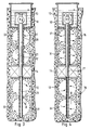
- schematische Längsschnitte durch vier Anordnungen für Grundwasser-Zirkulationsbrunnen, jeweils mit mehreren Filterkammern im oberen und unteren Brunnenschachtbereich und mit unterschiedlicher Gestaltung dieser Filterkammern;
- Fig. 5 - 7
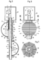
- den oberen Teil einer Anordnung nach Fig. 4 mit einer näheren Darstellung der Filterkammern begrenzenden Siebwandungen;
- Fig. 8 - 11
- mehr oder weniger schematische Längsschnitte durch vier Anordnungen für Unterdruckvergaserbrunnen (UVB).
- 1-4
- schematic longitudinal sections through four arrangements for groundwater circulation wells, each with several filter chambers in the upper and lower well shaft area and with different design of these filter chambers;
- 5 - 7
- the upper part of an arrangement according to Figure 4 with a more detailed representation of the filter chambers delimiting sieve walls.
- Figures 8-11
- more or less schematic longitudinal sections through four arrangements for vacuum carburettor wells (UVB).
Die Fig. 1 bis 4 und 8 bis 11 zeigen jeweils einen gebohrten Brunnenschacht 12, der in ein mit verunreinigtem Grundwasser durchsetztes Erdreich 10 getrieben ist. Der Brunnenschacht 12 ist in seinem oberen Bereich mit einem Brunnenrohr 13 ausgekleidet. Der Brunnenschacht ist durch eine Abdichtung 14 in einen oberen Bereich 15 und einen unteren Bereich 16 geteilt. Eine Verbindung zwischen den beiden Bereichen ist durch ein Durchgangsrohr 17 gegeben, das zentral im Brunnenschacht 12 angeordnet ist. Sowohl im oberen als auch im unteren Bereich 15, 16 des Brunnenschachtes 12 sind Filterkammern ausgebildet, die den gesamten freien Bohrungsquerschnitt des Brunnenschachtes einnehmen. Diese Filterkammern sind bei den einzelnen Ausführungsbeispielen unterschiedlich angeordnet oder begrenzt.1 to 4 and 8 to 11 each show a drilled
Bei dem Ausführungsbeispiel nach Fig. 1 ist im oberen Endbereich des Durchgangsrohres 17 eine Pumpe 18 angeordnet, die das in den von dem Brunnenrohr 13 umgebenden oberen freien Schachtbereich aufsteigende Grundwasser in das Durchgangsrohr 17 ansaugt. Das Durchgangsrohr 17 endet unten in der Öffnung einer Querwandung 19, welche die Trennung in den oberen Schachtbereich 15 und den unteren Schachtbereich 16 bewirkt und an welche sich die Dichtung 14 in Form eines Ringmantels anschließt. Im oberen Schachtbereich 15 sind zwei Filterkammern 20, 21 ausgebildet, die durch eine horizontale Siebwandung 22 voneinander getrennt sind. Auch im unteren Schachtbereich 16 sind zwei Filterkammern 23 und 24 ausgebildet, die durch eine horizontale Siebwandung 25 voneinander getrennt sind und von denen sich die obere Filterkammer 23 innerhalb der ringmantelartigen Dichtung 14 befindet. Auch im oberen Schachtbereich 15 ist die obere Filterkammer 20 nach außen abgeschlossen, dort durch das Brunnenrohr 13. Die beiden nur in vertikaler Richtung durchströmbaren oberen Filterkammern 20 und 23 sind mit einem austauschbaren Filtermaterial angefüllt. Die jeweils unteren Filterkammern 21 und 24, welche zur Schachtwandung hin offen sind, sind beispielsweise mit Filterkies vollständig ausgefüllt. Das Auswechseln des Filtermaterials aus den oberen Filterkammern 20 und 23 läßt sich durch Absaugen des schütt- und rieselfähigen Materials und nachträgliches Einflößen von neuem Filtermaterial bewirken. Nach Abnahme der Pumpe 18 ist die obere Filterkammer 23 des unteren Brunnenschachtbereiches 16 durch das Durchgangsrohr 17 hindurch für einen nicht dargestellten Absaug- oder Einflößschlauch zugänglich.In the exemplary embodiment according to FIG. 1, a
Der Grundwasser-Zirkulationsbrunnen nach Fig. 1 wird im sogenannten Linkslauf betrieben, weil in den oberen Brunnenschachtbereich 15 in die dortige untere Filterkammer 21 einströmendes und durch die obere Filterkammer 20 hochsteigendes Grundwasser durch das Durchgangsrohr 17 in den unteren Schachtbereich 16 gefördert wird, wo es zunächst die obere Filterkammer 23 mit der auswechselbaren Filtermaterialfüllung und die Siebwandung 25 durchströmt, dann in die untere Filterkammer 24 gelangt und von dort zurück in das Erdreich strömen kann. Im Brunnenrohr 13 können in der oberen Filterkammer 20 weitere Festfilterschichten in Form von entnehmbaren Ringpackungen angeordnet sein, die sich leicht auswechseln lassen.The groundwater circulation well according to Fig. 1 is operated in the so-called left-hand rotation, because in the upper
Bei der Anordnung nach Fig. 2 ist über das zentrale Durchgangsrohr 17 im oberen Brunnenschachtbereich 15 ein gelochtes Verteilerrohr 26 merklich größeren Durchmessers koaxial angeordnet. Es ist im oberen filterfreien Schachtende zu einem Sammelzylinder 27 erweitert, in welchem das mit einer Förderpumpe 28 versehene Durchgangsrohr 17 endet. Nach unten in den unteren Schachtbereich 16 ist das Durchgangsrohr 17 über die Dichtung 14 hinaus bis zum Brunnenschachtboden verlängert und in diesem Bereich als gelochtes Sammelrohr 29 ausgebildet. In beiden Brunnenschachtbereichen 15 und 16 sind durch Siebwandungen 30, die in Form konischer Ringe zwischen dem gelochten Verteilerrohr 26 und der Wandung des Brunnenschachtes 12 jeweils in Paaren von spiegelbildlich zueinander und sich mit ihren Außenrändern berührenden Siebwandungen 30 angeordnet sind, Filterkammern oder Filterbereiche begrenzt. Der Innenraum der doppelkonischen Siebwandungsgebilde bildet einen freien Strömungsraum für das Grundwasser. Gegen die Außenseite dieser doppelkonischen Gebilde liegt körniges Filtermaterial an. Es entstehen große Filterflächen, über welche das Grundwasser gut verteilt geführt wird. Die sich in den einzelnen Filterkammern von innen nach außen verbreiternde Filtermasse verhindert ein unerwünschtes vertikales Grundwasserfließen im Randbereich des Brunnenschachtes. Auf Wechselfilterkammern ist hier verzichtet worden. Der Grundwasser-Zirkulationsbrunnen wird im sogenannten Rechtslauf betrieben, also Grundwasser in den unteren Brunnenschachtbereich 16 angesaugt, nach oben gefördert und durch den oberen Brunnenschachtbereich 15 wieder in das Erdreich zurückgeführt.In the arrangement according to FIG. 2, a
Die Fig. 3 und 4 zeigen eine Anordnung, gemäß Fig. 3 im Linkslauf und gemäß Fig. 4 im Rechtslauf betrieben. Bei dieser Anordnung sind sowohl im oberen Brunnenrohrbereich 15 als auch im unteren Brunnenrohrbereich 16 äußere Filterkammerbereiche mit wechselnder Filtermaterialstärke ähnlich wie bei dem Ausführungsbeispiel nach Fig. 2 ausgebildet. Es sind um das Verteilerrohr 26 und um das gelochte Sammelrohr 29 herum jeweils zu einem Torus mit halbkreisförmigem Querschnitt geformte und gekrümmte Siebwandungen 31 angeordnet. Der Innenraum 32 der Toren bildet freie Strömungsräume für das Grundwasser. Der Raum zwischen der Außenseite der gekrümmten Siebwandungen 31 und der Schachtwandung ist mit Filterkies ausgefüllt. Bei dem in Fig. 3 gezeigten Linkslauf des Grundwasser-Zirkulationsbrunnens hat das gelochte Verteilerrohr 26 die Funktion eines Sammelrohres, während das Sammelrohr 29 die Funktion eines Verteilerrohres hat.3 and 4 show an arrangement, operated according to FIG. 3 in left-hand rotation and according to FIG. 4 in clockwise rotation. With this arrangement, both in the upper
In den Fig. 5 bis 7 ist der Aufbau eines durch eine gekrümmte Siebwandung 31 gebildeten und auf das Verteilerrohr 26 aufgeschobenen Torus 33 näher dargestellt. Zwischen zwei Tragringen 34 und 35 sind Stegträger 36 bogenförmig eingespannt. Auf diese bogenförmig gespannten Stegträger 36 sind mit gleichmäßigen Abständen Runddrähte 37 aufgesetzt, beispielsweise ein einziger Runddraht gewickelt und durch Punktschweißen oder Kleben mit den Stegträgern 36 verbunden. Außerdem sind die beiden Tragringe 34 und 35 mittels geradliniger Trägerstege 38 miteinander verbunden, von denen mindestens einer mit einem nockenartigen und in den Zwischenraum zwischen dem Verteilerrohr 26 und dem Durchgangsrohr 17 ragenden Ansatz 39 versehen ist (Fig. 5). Die Trägerstege 38 können aber auch durch einen elektromagnetisch betätigbaren Vibrationsring 40 miteinander verbunden sein, wie ebenfalls Fig. 5 zeigt.5 to 7 show the structure of a
An den Ansätzen 39 kann ein Vibrationsstab 41 eines mobilen Schwingungserzeugers 42 angesetzt werden, der in Fig. 5 mit strichpunktierten Linien eingezeichnet ist. Mit den Schwingungserzeugern 40 oder 42 können die Siebwandungsgebilde von Zeit zu Zeit in Schwingungen versetzt werden, um sich an den Siebwandungen 31 absetzende Ausfällungen oder aus dem Grundwasser oder aus dem Erdreich angeschwemmte Teile von den Siebwandungen abzulösen.A
Die Fig. 8 bis 11 zeigen Reinigungsanordnungen, in welchen das Grundwasser zusätzlich einer Behandlung durch Gase, insbesondere Luft, unterzogen wird, die durch Unterdruckbildung im oberen Schachtbereich in feinen Bläschen durch das Grundwasser hindurchgezogen werden. Der dabei auftretende Airlift-Effekt hat ebenfalls eine Förderwirkung auf das Grundwasser. Bei dem Ausführungsbeispiel nach Fig. 8 ist dies die einzige Fördervorrichtung zur Ausbildung des Grundwasserkreislaufes durch die Filterkammern der Anordnung.8 to 11 show cleaning arrangements in which the groundwater is additionally subjected to a treatment by gases, in particular air, which are drawn through the groundwater in fine bubbles by the formation of negative pressure in the upper shaft area. The resulting airlift effect also has a pumping effect on the groundwater. In the exemplary embodiment according to FIG. 8, this is the only conveying device for the formation of the groundwater circuit through the filter chambers of the arrangement.
Das Brunnenrohr 13 ist nach außen durch einen Deckel 118 verschlossen, durch den ein Luftansaugrohr 119 mit einer Pumpe 120 und ein Luftansaugrohr 121 geführt sind. Durch die Pumpe 120 wird oberhalb des Grundwasserspiegels 122 im Schacht 12 ein Unterdruck erzeugt, der für die Förderung des Grundwassers vom unteren Schachtbereich 16 in den oberen Schachtbereich 15 verantwortlich ist. Im unteren Schachtbereich 16 ist ein trommelförmiger Filterkörper 123 angeordnet, der von Filterkies 124 umgeben ist. Der Filterkörper 123 weist eine vertikale Seitenwandung 125 und zwei horizontale Filterflächen 126 und 127 auf, durch die Grundwasser aus dem umgebenden Erdreich 11 aufgrund des im oberen Schachtbereich erzeugten Unterdrucks einfließt, was durch die Pfeile 128 angedeutet ist. Anschließend gelangt das Wasser durch das Durchgangsrohr 17 in den oberen Schachtbereich 15, wo es von einem zweiten, in eine Aufweitung 129 des Durchgangsrohres 17 eingesetzten Rohr 130 aufgenommen wird, das sich topfartig erweitert und eine Luftkammer 131, die von einem Düsenkörper 132 begrenzt ist, und einen Wasseraufnahmeraum 133 unterhalb der Luftkammer bildet. Das Wasser gelangt vom Rohr 17 über das Einsatzrohr 130 in den Wasseraufnahmeraum 133 und von dort über zwei durch die Luftkammer 131 geführte Röhrchen 134 und 135 in einen Wasserbehandlungsbereich 136 oberhalb der Luftkammer 131. Die Röhrchen 134 und 135 weisen in Höhe der Luftkammer 131 Öffnungen auf, durch die durch das in den Röhrchen fließende Wasser angezogene Luft eindringen und mit nach oben in den Behandlungsraum 136 transportiert werden kann. Im Behandlungsraum 136 sind zwei konzentrisch angeordnete Leitringe 137 und 138 angeordnet, die die laminare Strömung des Wassers beim Aufwärts- und Abwärtsfließen begünstigen und dadurch dazu beitragen, daß ein Teil des abwärts fließenden Wassers wieder vom aufwärts strömenden Luftbläschenstrom erfaßt und ein zweites Mal gereinigt wird. Die Luftbläschen werden nach Erreichen des Wasserspiegels 122 im Brunnenschacht durch die Pumpe 120 zusammen mit den an ihnen gebundenen Kontaminationen aus dem Schacht abgesaugt. Gleichzeitig sorgt der durch die Pumpe 120 erzeugte Unterdruck im Schacht dafür, daß frische Luft durch das Ansaugrohr 121 in die Luftkammer 131 nachströmen kann.The
Der gesamte Einsatz, bestehend aus dem Einsatzrohr 130, der Wasserkammer 133, der Luftkammer 131, dem Luftzufuhrrohr 121 und den Leitringen 137 und 138, ist an einem Schwimmkörper mit Luftkammern 139 befestigt, um Schwankungen des Grundwasserspiegels 140 im Erdreich 11 ausgleichen zu können.The entire insert, consisting of the
Nach der Reinigung des Grundwassers von leichtflüchtigen Verunreinigungen mittels der Luft oder Gasbläschen im Behandlungsraum 136 strömt das Grundwasser entlang des Schachtrandes wieder abwärts und sickert durch eine Kiesschüttung 141 im oberen Schachtbereich 15, bevor es den Brunnenschacht 12 seitlich wieder verläßt. Beim Sickern des Wassers durch die Kiesschüttung 141 können weitere im Wasser gebundene Stoffe, wie z. B. Eisen, aus diesem gelöst werden. Nach dem Rückströmen ins Erdreich 11 wird das Grundwasser wieder durch die Saugwirkung im unteren Schachtbereich 16 erfaßt und bildet somit einen Kreislauf zwischen Brunnenschacht 12 und Erdreich 11. Dabei wird ständig neues, noch nicht gereinigtes Grundwasser mitangezogen. Die Reichweite des Kreislaufs in radialer Richtung um den Brunnenschacht läßt sich durch eine Verkleinerung der Höhe der Seitenwandung 125 des Trommelfilters 123 im unteren Schachtbereich noch verstärken.After the groundwater has been cleaned of volatile impurities by means of the air or gas bubbles in the
Fig. 9 zeigt eine Anordnung, deren unterer Bereich 16 einen geringeren Durchmesser als der obere Schachtbereich 15 aufweist, d. h. die teurere weite Aufbohrung des Brunnenschachtes ist nur im oberen Bereich, in dem die Behandlung des Wassers stattfindet, erforderlich.FIG. 9 shows an arrangement whose
In einer Aufweitung 29 des Durchgangsrohres 17, das die beiden Schachtbereiche 15 und 16 miteinander verbindet, sind ein Einsatzrohr 130 und eine mit diesem verbundene Förderpumpe 150 eingesetzt. Am Ausgang der Pumpe 150 ist ein Rohr 151 angeordnet, das das Wasser durch eine Luftkammer 131 hindurch befördert, um es anschließend durch seitliche Öffnungen 152 in einen Behandlungsraum 136 abzugeben. Auf Höhe der seitlichen Öffnungen 152 sind zwei konzentrische Leitringe 137 und 138 zur Begünstigung der laminaren Wasserströmung angeordnet.In a widening 29 of the through
Das Rohr 151 weist in seinem oberen Bereich eine Querwandung 153 auf, die das Eindringen von Wasser in das bis über einen Schachtdeckel 118 reichende Endstück 154 des Rohres 151 verhindert und damit dieses Endstück 154, das zwei Anschlußrohre 155 und 156, die bis in den Luftaufnahmeraum 131 geführt sind, aufweist, zur Zufuhr von Frischluft in die Luftkammer 131 nutzbar macht. Ebenso wie beim Ausführungsbeispiel in Fig. 8 wird die Frischluft dabei durch den mittels einer Pumpe 120 oberhalb des Schachtes 12 erzeugten Unterdruck im Schacht nachgesaugt.The
Auch bei der Anordnung nach Fig. 9 wird das verunreinigte Grundwasser zunächst im Behandlungsraum 136 von leichtflüchtigen Verunreinigungen gereinigt, bevor es beim Abwärtsströmen durch eine Kiesschüttung 141 eine zweite Reinigung erfährt. Anschließend verläßt das Grundwasser den Schacht 12 im oberen Bereich 15 wieder und bildet einen Kreislauf zur Wasseransaugstelle im unteren Schachtbereich 16, wobei die Strömungsgeschwindigkeit des Wassers im Ausführungsbeispiel nach Fig. 9 durch die Förderpumpe 150 größer ist als beim Ausführungsbeispiel nach Fig. 8, bei dem der Kreislauf allein durch Unterdruckerzeugung im Brunnenschacht erzeugt wird.Also in the arrangement according to FIG. 9, the contaminated groundwater is first cleaned of volatile contaminants in the
Zur Reinigung des Kieses sind in der Kiesschüttung 141 Schwingungserzeuger 157 angeordnet, deren Druckwellen Verunreinigungen im Kies lösen, die dann anschließend abgesaugt werden können.To clean the gravel, 141
Bei den Ausführungsbeispielen nach Fig. 10 und 11 sind neben den im Durchgangsrohr 17 angeordneten Förderpumpen 18 oder 28 zusätzliche Förderpumpen 45 oder 46 vorgesehen, welche die Grundwasserbewegung in dem Gasbehandlungsbereich der Anordnungen verstärken und steuern. Der Aufbau des Filterteiles der Anordnung ähnelt sehr stark derjenigen des Ausführungsbeispieles nach Fig. 1, weshalb für entsprechende Einrichtungsteile die gleichen Bezugsziffern wie in Fig. 1 verwendet sind. Im Gasbehandlungsbereich sind der Ausführungsform nach Fig. 8 entsprechende Teile mit den gleichen Bezugsziffern wie dort bezeichnet. Durch die beiden Pumpen 18, 45 bzw. 28, 46 wird bei den Anordnungen nach Fig. 10 und 11 eine Mehrfachzirkulation des Grundwassers innerhalb des nach außen durch das Brunnenrohr 13 abgeschlossenen oberen Schachtbereiches bewirkt. Die zusätzliche Pumpe 45 oder 46 ist in einem Rohr 47 angeordnet, das durch die Luftkammer 131 und ein Stück weit durch das Luftansaugrohr 121 hindurchgeführt ist, und das unterhalb des Flüssigkeitsspiegels 122 und oberhalb des Leitringes 138 in einen zentralen Bereich des oberen Brunnenschachtbereiches austritt. Dieser zentrale Bereich ist durch ein Leitrohr 48 begrenzt, das über den Flüssigkeitsspiegel 122 hinausragt und im Flüssigkeitsbereich wie ein drittes Leitblech zwischen den beiden anderen Leitblechen 137 und 138 wirkt. Durch die Leitbleche wird das Grundwasser mehrfach durch den Bereich mit den aufsteigenden Gasblasen geführt und umgelenkt. Beim Ausführungsbeispiel nach Fig. 10 wird das Grundwasser von der Pumpe 45 in den Gasbehandlungsbereich hochgefördert und fließt anschließend an der Luftkammer 131 vorbei nach unten zurück. Beim Ausführungsbeispiel nach Fig. 11 wird das Grundwasser aus dem Gasbehandlungsbereich durch die Pumpe 46 nach unten abgezogen und steigt entlang der Luftkammer 131 wieder nach oben in den Gasbehandlungsbereich, soweit es nicht durch die Pumpe 28 erfaßt und in den unteren Brunnenschachtbereich 16 und die dortigen Filterkammern abgezogen wird. Die Pumpen können je nach Art und Umfang der Verunreinigung des Grundwassers mit unterschiedlicher Förderleistung betrieben werden.In the exemplary embodiments according to FIGS. 10 and 11, in addition to the feed pumps 18 or 28 arranged in the through-
Claims (21)
Applications Claiming Priority (4)
| Application Number | Priority Date | Filing Date | Title |
|---|---|---|---|
| DE4203382 | 1992-02-06 | ||
| DE4203382 | 1992-02-06 | ||
| DE4235069 | 1992-10-17 | ||
| DE4235069A DE4235069A1 (en) | 1992-02-06 | 1992-10-17 | ARRANGEMENT FOR CLEANING GROUND WATER |
Publications (2)
| Publication Number | Publication Date |
|---|---|
| EP0555734A1 true EP0555734A1 (en) | 1993-08-18 |
| EP0555734B1 EP0555734B1 (en) | 1996-05-22 |
Family
ID=25911576
Family Applications (1)
| Application Number | Title | Priority Date | Filing Date |
|---|---|---|---|
| EP93101586A Expired - Lifetime EP0555734B1 (en) | 1992-02-06 | 1993-02-02 | Device for cleaning ground water |
Country Status (4)
| Country | Link |
|---|---|
| US (1) | US5281333A (en) |
| EP (1) | EP0555734B1 (en) |
| AT (1) | ATE138447T1 (en) |
| DE (2) | DE4235069A1 (en) |
Cited By (2)
| Publication number | Priority date | Publication date | Assignee | Title |
|---|---|---|---|---|
| DE19828917C1 (en) * | 1998-06-29 | 2000-01-20 | Ieg Ind Engineering Gmbh | Filter for drinking fountain |
| EP3792408A1 (en) * | 2019-09-11 | 2021-03-17 | IEG - Technologie GmbH | Filter assembly |
Families Citing this family (16)
| Publication number | Priority date | Publication date | Assignee | Title |
|---|---|---|---|---|
| US5402848A (en) * | 1994-04-07 | 1995-04-04 | Kelly; Leo G. | Method and apparatus for conducting environmental procedures |
| US5622450A (en) * | 1995-03-24 | 1997-04-22 | Grant, Jr.; Richard P. | Pressure extraction process for removing soil and groundwater contaminants |
| US6143177A (en) | 1995-04-11 | 2000-11-07 | Arcadis Geraghty & Miller, Inc. | Engineered in situ anaerobic reactive zones |
| DE19617879A1 (en) * | 1996-04-25 | 1997-11-06 | Argus Umweltbiotech Gmbh | Water treatment for treating polluted sub soil waste water in situ |
| US6007274A (en) | 1997-05-19 | 1999-12-28 | Arcadis Geraghty & Miller | In-well air stripping, oxidation, and adsorption |
| US6116816A (en) | 1998-08-26 | 2000-09-12 | Arcadis Geraghty & Miller, Inc. | In situ reactive gate for groundwater remediation |
| US6921477B2 (en) * | 2002-04-08 | 2005-07-26 | Steven L. Wilhelm | Groundwater treatment system and method |
| US7156988B2 (en) * | 2003-05-16 | 2007-01-02 | Wilhelm Steven L | Floating product removal |
| US7077208B2 (en) * | 2003-09-11 | 2006-07-18 | R3 Pump Technologies | Method and system for directing fluid flow |
| US20060266712A1 (en) * | 2005-05-27 | 2006-11-30 | Wilhelm Steven L | Groundwater treatment |
| US7514004B1 (en) * | 2008-05-01 | 2009-04-07 | Sandia Corporation | In-tank recirculating arsenic treatment system |
| AU2009202672B2 (en) * | 2009-07-01 | 2015-08-13 | Desaln8 Pty Ltd | Apparatus and method for improving the quality of water from an aquifer |
| ES2425548T3 (en) * | 2011-02-11 | 2013-10-16 | Luxin (Green Planet) Ag | Groundwater management system for mines and procedure for the operation of said water management system |
| CN109570209A (en) * | 2018-12-27 | 2019-04-05 | 博川环境修复(北京)有限公司 | A kind of device for repairing polluted underground water and its flowing through contaminated soil |
| CN109912090B (en) * | 2019-04-23 | 2020-12-04 | 中南大学 | Annular multifunctional water purifier |
| CN113304664B (en) * | 2021-05-31 | 2023-09-05 | 广州兰德环保资源科技有限公司 | Emulsifying device optimized through high-frequency ultrasonic action and laminar sedimentation |
Citations (6)
| Publication number | Priority date | Publication date | Assignee | Title |
|---|---|---|---|---|
| DE3842740A1 (en) * | 1988-12-19 | 1990-06-21 | Zueblin Ag | Process for removing impurities from groundwater and a well for carrying out the process |
| DE4001011C1 (en) | 1990-01-16 | 1990-12-13 | Ieg - Industrie-Engineering Gmbh, 7410 Reutlingen, De | Ground water flow control - comprises shaft sunk into ground water levels with successive permeable and impermeable wall areas |
| EP0418570A1 (en) * | 1989-09-16 | 1991-03-27 | IEG Industrie-Engineering GmbH | Device for the purification of polluted ground water |
| US5015370A (en) * | 1989-06-08 | 1991-05-14 | Anthony Fricano | Apparatus and method for treating well water |
| EP0458090A2 (en) * | 1990-05-23 | 1991-11-27 | IEG Industrie-Engineering GmbH | Device for the treatment of contaminated soils by a gas |
| DE4138414A1 (en) | 1991-11-22 | 1993-05-27 | Ieg Ind Engineering Gmbh | ARRANGEMENT FOR CLEANING POLLUTED GROUND WATER |
Family Cites Families (12)
| Publication number | Priority date | Publication date | Assignee | Title |
|---|---|---|---|---|
| US4543186A (en) * | 1984-06-08 | 1985-09-24 | Weisenbarger Gale M | Apparatus and method for the treatment of well water therewith |
| DE3612468A1 (en) * | 1986-04-14 | 1987-10-15 | Meister Karl | Process for producing a filtering well, and filtering well with large capacity |
| DE3625488C2 (en) * | 1986-04-22 | 1994-09-22 | Ieg Ind Engineering Gmbh | Device for expelling volatile impurities from liquids |
| DE3811962C1 (en) * | 1988-04-11 | 1989-02-16 | Ieg - Industrie-Engineering Gmbh, 7410 Reutlingen, De | Arrangement for expelling highly volatile impurities from ground water |
| DE3805200C1 (en) * | 1988-02-19 | 1988-09-29 | Ieg - Industrie-Engineering Gmbh, 7410 Reutlingen, De | Arrangement for expelling readily volatile impurities from groundwater |
| DE59000506D1 (en) * | 1989-09-16 | 1993-01-07 | Ieg Ind Engineering Gmbh | ARRANGEMENT FOR DRIVING LIGHT VEGETABLE IMPURITIES FROM GROUND WATER. |
| DE4001012C1 (en) * | 1990-01-16 | 1991-05-02 | Ieg - Industrie-Engineering Gmbh, 7410 Reutlingen, De | |
| DE4006435C2 (en) * | 1990-03-01 | 1995-02-09 | Uwa Umweltanalytik Gmbh | Method and device for in-situ groundwater and / or leachate remediation |
| EP0457261B1 (en) * | 1990-05-16 | 1993-03-10 | TEGEO Tegtmeyer Geophysik GmbH | Apparatus for purification, for example of contaminated groundwater |
| DE4027304C2 (en) * | 1990-08-29 | 1993-12-09 | Ieg Ind Engineering Gmbh | Arrangement for expelling volatile contaminants from the groundwater |
| DE4037059A1 (en) * | 1990-11-22 | 1992-05-27 | Ieg Ind Engineering Gmbh | In-situ ground water purifying system - with shaft insert contg. aeration and filtration systems of simple and cheap construction |
| DE4039824C1 (en) * | 1990-12-13 | 1991-12-19 | Ieg - Industrie-Engineering Gmbh, 7410 Reutlingen, De |
-
1992
- 1992-10-17 DE DE4235069A patent/DE4235069A1/en not_active Ceased
-
1993
- 1993-02-02 DE DE59302631T patent/DE59302631D1/en not_active Expired - Fee Related
- 1993-02-02 AT AT93101586T patent/ATE138447T1/en not_active IP Right Cessation
- 1993-02-02 EP EP93101586A patent/EP0555734B1/en not_active Expired - Lifetime
- 1993-02-05 US US08/014,394 patent/US5281333A/en not_active Expired - Fee Related
Patent Citations (6)
| Publication number | Priority date | Publication date | Assignee | Title |
|---|---|---|---|---|
| DE3842740A1 (en) * | 1988-12-19 | 1990-06-21 | Zueblin Ag | Process for removing impurities from groundwater and a well for carrying out the process |
| US5015370A (en) * | 1989-06-08 | 1991-05-14 | Anthony Fricano | Apparatus and method for treating well water |
| EP0418570A1 (en) * | 1989-09-16 | 1991-03-27 | IEG Industrie-Engineering GmbH | Device for the purification of polluted ground water |
| DE4001011C1 (en) | 1990-01-16 | 1990-12-13 | Ieg - Industrie-Engineering Gmbh, 7410 Reutlingen, De | Ground water flow control - comprises shaft sunk into ground water levels with successive permeable and impermeable wall areas |
| EP0458090A2 (en) * | 1990-05-23 | 1991-11-27 | IEG Industrie-Engineering GmbH | Device for the treatment of contaminated soils by a gas |
| DE4138414A1 (en) | 1991-11-22 | 1993-05-27 | Ieg Ind Engineering Gmbh | ARRANGEMENT FOR CLEANING POLLUTED GROUND WATER |
Cited By (2)
| Publication number | Priority date | Publication date | Assignee | Title |
|---|---|---|---|---|
| DE19828917C1 (en) * | 1998-06-29 | 2000-01-20 | Ieg Ind Engineering Gmbh | Filter for drinking fountain |
| EP3792408A1 (en) * | 2019-09-11 | 2021-03-17 | IEG - Technologie GmbH | Filter assembly |
Also Published As
| Publication number | Publication date |
|---|---|
| DE4235069A1 (en) | 1993-08-12 |
| EP0555734B1 (en) | 1996-05-22 |
| US5281333A (en) | 1994-01-25 |
| ATE138447T1 (en) | 1996-06-15 |
| DE59302631D1 (en) | 1996-06-27 |
Similar Documents
| Publication | Publication Date | Title |
|---|---|---|
| EP0555734B1 (en) | Device for cleaning ground water | |
| EP0486976B1 (en) | Device for the purification of polluted ground water | |
| EP0291538B1 (en) | Process and apparatus for the continuous filtration of liquids | |
| EP0654294B1 (en) | Process and apparatus for the filtration of solid particles from liquids and the backwashing of the filter | |
| EP0571812A1 (en) | Device for removing volatile contaminants from ground water | |
| DE2501547B2 (en) | Cylinder sieve for separating liquid components from solid components | |
| DE3225537C2 (en) | ||
| EP0548768A1 (en) | Method and device for influencing a liquid present in the soil | |
| DE2116000B2 (en) | Process and fine grain drip bodies for biological wastewater treatment | |
| DE2146838C3 (en) | Method and device for filtering liquids | |
| DE3002773A1 (en) | GAS CLEANING FILTER | |
| EP0457261B1 (en) | Apparatus for purification, for example of contaminated groundwater | |
| DE2042353B2 (en) | Device for filtering liquids | |
| DE602004002593T2 (en) | WATER CIRCULATION UNIT WITH INCREASED PUMP AND THIS FILTER UNIT | |
| EP3222357B1 (en) | Sludge separator | |
| DE4217184C2 (en) | Process for removing oil residues or liquids containing oil from contaminated soil layers | |
| DE2855907A1 (en) | DEVICE FOR MECHANICAL WASTE WATER CLEANING | |
| DE1926934C3 (en) | Process for the filtration of liquids and apparatus for carrying out this process | |
| DE2807917A1 (en) | METHOD AND APPARATUS FOR CLEANING UP LIQUIDS USED IN EXCAVATION WORK | |
| DE3617054C2 (en) | Thickener | |
| CH515731A (en) | Device for cleaning pourable filter material in slow water treatment filters filled with water | |
| EP4056292B1 (en) | Multiple filter assembly | |
| WO1991012409A1 (en) | Process and device for removing incrustation deposit in fountains | |
| DE102007017447A1 (en) | Tank for breeding and fattening of fish, has dissipating device dissipating sediments, and lifting device conveying tank water into or below water surface under enrichment with oxygen from area of tank near base | |
| EP1493717A1 (en) | Method for flushing a biological sewage treatment reactor |
Legal Events
| Date | Code | Title | Description |
|---|---|---|---|
| PUAI | Public reference made under article 153(3) epc to a published international application that has entered the european phase |
Free format text: ORIGINAL CODE: 0009012 |
|
| AK | Designated contracting states |
Kind code of ref document: A1 Designated state(s): AT CH DE ES FR GB IT LI NL SE |
|
| 17P | Request for examination filed |
Effective date: 19940202 |
|
| 17Q | First examination report despatched |
Effective date: 19950630 |
|
| GRAH | Despatch of communication of intention to grant a patent |
Free format text: ORIGINAL CODE: EPIDOS IGRA |
|
| GRAA | (expected) grant |
Free format text: ORIGINAL CODE: 0009210 |
|
| AK | Designated contracting states |
Kind code of ref document: B1 Designated state(s): AT CH DE ES FR GB IT LI NL SE |
|
| PG25 | Lapsed in a contracting state [announced via postgrant information from national office to epo] |
Ref country code: NL Free format text: LAPSE BECAUSE OF FAILURE TO SUBMIT A TRANSLATION OF THE DESCRIPTION OR TO PAY THE FEE WITHIN THE PRESCRIBED TIME-LIMIT Effective date: 19960522 Ref country code: IT Free format text: LAPSE BECAUSE OF FAILURE TO SUBMIT A TRANSLATION OF THE DESCRIPTION OR TO PAY THE FEE WITHIN THE PRE;WARNING: LAPSES OF ITALIAN PATENTS WITH EFFECTIVE DATE BEFORE 2007 MAY HAVE OCCURRED AT ANY TIME BEFORE 2007. THE CORRECT EFFECTIVE DATE MAY BE DIFFERENT FROM THE ONE RECORDED.SCRIBED TIME-LIMIT Effective date: 19960522 Ref country code: GB Effective date: 19960522 Ref country code: FR Effective date: 19960522 Ref country code: ES Free format text: THE PATENT HAS BEEN ANNULLED BY A DECISION OF A NATIONAL AUTHORITY Effective date: 19960522 |
|
| REF | Corresponds to: |
Ref document number: 138447 Country of ref document: AT Date of ref document: 19960615 Kind code of ref document: T |
|
| REF | Corresponds to: |
Ref document number: 59302631 Country of ref document: DE Date of ref document: 19960627 |
|
| PG25 | Lapsed in a contracting state [announced via postgrant information from national office to epo] |
Ref country code: SE Effective date: 19960822 |
|
| EN | Fr: translation not filed | ||
| EN | Fr: translation not filed | ||
| NLV1 | Nl: lapsed or annulled due to failure to fulfill the requirements of art. 29p and 29m of the patents act | ||
| GBV | Gb: ep patent (uk) treated as always having been void in accordance with gb section 77(7)/1977 [no translation filed] |
Effective date: 19960522 |
|
| PG25 | Lapsed in a contracting state [announced via postgrant information from national office to epo] |
Ref country code: AT Free format text: LAPSE BECAUSE OF NON-PAYMENT OF DUE FEES Effective date: 19970202 |
|
| PG25 | Lapsed in a contracting state [announced via postgrant information from national office to epo] |
Ref country code: LI Effective date: 19970228 Ref country code: CH Effective date: 19970228 |
|
| PLBE | No opposition filed within time limit |
Free format text: ORIGINAL CODE: 0009261 |
|
| STAA | Information on the status of an ep patent application or granted ep patent |
Free format text: STATUS: NO OPPOSITION FILED WITHIN TIME LIMIT |
|
| 26N | No opposition filed | ||
| REG | Reference to a national code |
Ref country code: CH Ref legal event code: PL |
|
| PG25 | Lapsed in a contracting state [announced via postgrant information from national office to epo] |
Ref country code: DE Effective date: 19971101 |