EP0551588A1 - Intramedullary nail for treating fractures of the proximal femur - Google Patents
Intramedullary nail for treating fractures of the proximal femur Download PDFInfo
- Publication number
- EP0551588A1 EP0551588A1 EP92119591A EP92119591A EP0551588A1 EP 0551588 A1 EP0551588 A1 EP 0551588A1 EP 92119591 A EP92119591 A EP 92119591A EP 92119591 A EP92119591 A EP 92119591A EP 0551588 A1 EP0551588 A1 EP 0551588A1
- Authority
- EP
- European Patent Office
- Prior art keywords
- nail
- bore
- femur
- proximal
- shaft
- Prior art date
- Legal status (The legal status is an assumption and is not a legal conclusion. Google has not performed a legal analysis and makes no representation as to the accuracy of the status listed.)
- Granted
Links
Images
Classifications
-
- A—HUMAN NECESSITIES
- A61—MEDICAL OR VETERINARY SCIENCE; HYGIENE
- A61B—DIAGNOSIS; SURGERY; IDENTIFICATION
- A61B17/00—Surgical instruments, devices or methods, e.g. tourniquets
- A61B17/56—Surgical instruments or methods for treatment of bones or joints; Devices specially adapted therefor
- A61B17/58—Surgical instruments or methods for treatment of bones or joints; Devices specially adapted therefor for osteosynthesis, e.g. bone plates, screws, setting implements or the like
- A61B17/68—Internal fixation devices, including fasteners and spinal fixators, even if a part thereof projects from the skin
- A61B17/74—Devices for the head or neck or trochanter of the femur
- A61B17/742—Devices for the head or neck or trochanter of the femur having one or more longitudinal elements oriented along or parallel to the axis of the neck
- A61B17/744—Devices for the head or neck or trochanter of the femur having one or more longitudinal elements oriented along or parallel to the axis of the neck the longitudinal elements coupled to an intramedullary nail
Definitions
- the present invention relates to a locking nail for treating fractures of the proximal femur according to the preamble of claim 1.
- EP 0257118 discloses a locking nail for treating subtrochantic fractures.
- a nail shaft proximally inserted into the mallow space of the femur is provided with an oblique bore for receiving the femur neck screw.
- the locking nail is distally provided with a pair of cross-bores to receive bone screws.
- the femur neck screw is freely axially movable in the cross-bore and the locking nail is provided with a securing means selectively preventing a turning of the femur neck screw but allowing an axial displacement.
- the locking nail is not used per se for treating the fracture, but is provided to guide and hold the femur neck screw.
- the locking nails used for the known osteosynthesis aids are designed to be relatively long so that the femur is hurt over almost its total length when being driven in.
- a pair of femur neck screws is used, they both are located within a plane which does not always fit to the conditions to be met, in particular in case of subcapital fractures.
- the oblique bore at a proximal portion of the nail shaft has a larger diameter than the respective femur neck screw.
- the proximal angular bore is shaped as an elongated bore in an axis perpendicular to the nail axis.
- the femur neck screw inserted may pivot in the angular bore to some limited extent to be oriented in a desired way.
- the screw may be positioned in an angular position substantially different with respect to the position of the other femur neck screw. This is of a particular advantage in treating subcapital fractures.
- the nail shaft is shaped to be relatively short.
- the proximal portion of the nail shaft is formed substantially cylindrical, while conically tapering towards the distal end in the distal area.
- the length of the nail shaft between the distal end and the distal angular bore maximally is 1.5 times the length between the proximal end and the distal angular bore. Therefore, the femur is minimally hurt only when implanting the nail shaft.
- the proximal portion of the nail shaft has a relatively large diameter.
- the nail shaft is axially provided with a length bore.
- the nail shaft may be driven in by means of a guide lance.
- a further embodiment of the invention provides for a single cross-bore in the distal end portion to lock the nail in the femur.
- a nail shaft 10 forming part of a locking nail comprises a cylindrical portion 12 in the proximal area and a substantially conical portion 14 in the distal area.
- the total length is 120 mm for example, wherein both the portions 12, 14 are substantially of equal length.
- a truncated tip 16 is formed at the first tapered portion of the nail portion 14.
- the distal end portion is provided with a cross- bore 18 for receiving a bone screw not shown.
- a pair of angular inclined bores 20 and 22 is provided for receiving femur neck screws shown in Figs. 3 to 5.
- the angle of the oblique bores 20, 22 which is equal for both bores may be between 25° and 40° relative to a vertical on the length axis of the nail shaft 10.
- the nail shaft 10 is curved in the lateral medial plane corresponding to the natural curvature of the human femur.
- the nail shaft 10 further includes a length bore 24 extending in correspondence to the curvature of the nail (Fig. 2).
- the length bore is extended to a threaded bore 26.
- the proximal end includes a recess 28 which is suited to orient the positioning device to be applied as well to rotate the nail in a desired rotational position when driving in.
- the angular bore 20 having a larger diameter receives a femur neck screw 30 as shwon in Figs. 4 and 5.
- the illustration of the femur neck screw in Figs. 3 to 5 is not on scale. Accordingly, the femur neck screw 30 has a diameter which is minimally smaller only than the diameter of the angular bore 20.
- the femur neck screw 30 includes a cylindrical shaft 32 having a length bore 34. At the front end a thread 36 is formed which is self-cutting by a cutting groove 38. At the rearward region a pulurality of peripherally distant grooves 40 is formed which extend parallel to the axis.
- the grooves may receive the free end of a screw which is turned into the threaded bore 26 to fix the femur neck screw 30 in a rotational position, but allows an axial displacement as disclosed in the European Patent 257118 above referred to.
- a fixing of the femur neck screw 30 of this type is accomplished only then, however, when there is no femur neck screw inserted through the second angular bore 22.
- the femur neck screw 30 has an end portion including an inner threaded bore 38 to mount a suitable instrument.
- Four recesses 42 equally spaced peripherally allow to apply a turning force.
- a femur neck screw 44 is inserted through the angular bore 22 which screw has a cylindrical shaft portion 46 extending into a tapered shaft portion 48 towards the end at which a threaded portion 50 is formed.
- the head 52 of the femur neck screw 44 comprises an inner hexagonal recess 54.
- Fig. 1 shows that the angular bore 22 is not circular, but oval.
- the large diameter of the angular bore 22 amounts to 10 mm.
- the large diameter of the cross-sectional area of the bore 22 extends oblique with respect to the longitudinal axis of the nail shaft 10. Therefore, the femur neck screw 44 may be oriented with respect to the angular bore 22 in accordance with the conditions to be met.
Abstract
Description
- The present invention relates to a locking nail for treating fractures of the proximal femur according to the preamble of claim 1.
- EP 0257118 discloses a locking nail for treating subtrochantic fractures. A nail shaft proximally inserted into the mallow space of the femur is provided with an oblique bore for receiving the femur neck screw. The locking nail is distally provided with a pair of cross-bores to receive bone screws. The femur neck screw is freely axially movable in the cross-bore and the locking nail is provided with a securing means selectively preventing a turning of the femur neck screw but allowing an axial displacement. For an osteosynthesis supplement of such type the locking nail is not used per se for treating the fracture, but is provided to guide and hold the femur neck screw.
- It is further known to provide a distang pair of oblique bores in the proximal end portion of a locking nail to receive a pair of femur neck screws.
- The locking nails used for the known osteosynthesis aids are designed to be relatively long so that the femur is hurt over almost its total length when being driven in. When a pair of femur neck screws is used, they both are located within a plane which does not always fit to the conditions to be met, in particular in case of subcapital fractures.
- Therefore, it is the object of the present invention to provide a locking nail which is particularly suited for treating subcapital fractures.
- According to the invention the object is solved by the features of claim 1.
- According to the invention the oblique bore at a proximal portion of the nail shaft has a larger diameter than the respective femur neck screw. Preferrably, the proximal angular bore is shaped as an elongated bore in an axis perpendicular to the nail axis. In this manner, the femur neck screw inserted may pivot in the angular bore to some limited extent to be oriented in a desired way. In particular, the screw may be positioned in an angular position substantially different with respect to the position of the other femur neck screw. This is of a particular advantage in treating subcapital fractures.
- According to a further embodiment of the invention the nail shaft is shaped to be relatively short. The proximal portion of the nail shaft is formed substantially cylindrical, while conically tapering towards the distal end in the distal area. The length of the nail shaft between the distal end and the distal angular bore maximally is 1.5 times the length between the proximal end and the distal angular bore. Therefore, the femur is minimally hurt only when implanting the nail shaft.
- According to the invention the proximal portion of the nail shaft has a relatively large diameter. There is an advantage, therefore, when the nail shaft is curved in the lateral medial plane to fit to the natural curvature of the femur.
- According to a still further embodiment of the invention the nail shaft is axially provided with a length bore. Thus the nail shaft may be driven in by means of a guide lance.
- Since the nail shaft is relatively short, a further embodiment of the invention provides for a single cross-bore in the distal end portion to lock the nail in the femur.
- By way of an example, the invention will now be described with reference to the accompanying drawing.
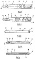
- Fig. 1
- is a side view of a nail shaft of the locking nail according to the invention,
- Fig. 2
- is a section through the locking nail portion of Fig. 1 along the line 2-2,
- Fig. 3
- is a side view of a femur neck screw for the nail shaft of Figs. 1 or 2,
- Fig. 4
- is a side view of an alternative femur neck screw for the nail of Figs. 1 and 2, and
- Fig. 5
- is a section through the femur neck screw of Fig. 4 along the line 5-5.
- A
nail shaft 10 forming part of a locking nail comprises acylindrical portion 12 in the proximal area and a substantiallyconical portion 14 in the distal area. The total length is 120 mm for example, wherein both theportions truncated tip 16 is formed at the first tapered portion of thenail portion 14. The distal end portion is provided with a cross-bore 18 for receiving a bone screw not shown. In the proximal portion, or respectively the section 12 a pair of angularinclined bores oblique bores nail shaft 10. - As Fig. 2 shows, the
nail shaft 10 is curved in the lateral medial plane corresponding to the natural curvature of the human femur. Thenail shaft 10 further includes alength bore 24 extending in correspondence to the curvature of the nail (Fig. 2). At the proximal end the length bore is extended to a threadedbore 26. For example it serves to receive a suited positioning device (not shown). Furthermore, the proximal end includes arecess 28 which is suited to orient the positioning device to be applied as well to rotate the nail in a desired rotational position when driving in. - The
angular bore 20 having a larger diameter receives afemur neck screw 30 as shwon in Figs. 4 and 5. The illustration of the femur neck screw in Figs. 3 to 5 is not on scale. Accordingly, thefemur neck screw 30 has a diameter which is minimally smaller only than the diameter of theangular bore 20. Thefemur neck screw 30 includes acylindrical shaft 32 having a length bore 34. At the front end athread 36 is formed which is self-cutting by acutting groove 38. At the rearward region a pulurality of peripherallydistant grooves 40 is formed which extend parallel to the axis. The grooves may receive the free end of a screw which is turned into the threadedbore 26 to fix thefemur neck screw 30 in a rotational position, but allows an axial displacement as disclosed in the European Patent 257118 above referred to. A fixing of thefemur neck screw 30 of this type is accomplished only then, however, when there is no femur neck screw inserted through the secondangular bore 22. Thefemur neck screw 30 has an end portion including an inner threadedbore 38 to mount a suitable instrument. Fourrecesses 42 equally spaced peripherally allow to apply a turning force. - A
femur neck screw 44 is inserted through theangular bore 22 which screw has acylindrical shaft portion 46 extending into atapered shaft portion 48 towards the end at which a threadedportion 50 is formed. Thehead 52 of thefemur neck screw 44 comprises an innerhexagonal recess 54. - Fig. 1 shows that the
angular bore 22 is not circular, but oval. When the diameter of thecylindrical shaft portion 46 is 6.5 mm for example, the large diameter of theangular bore 22 amounts to 10 mm. As may be seen, the large diameter of the cross-sectional area of thebore 22 extends oblique with respect to the longitudinal axis of thenail shaft 10. Therefore, thefemur neck screw 44 may be oriented with respect to theangular bore 22 in accordance with the conditions to be met.
Claims (7)
- A locking nail for treating fractures of the proximal femur, in particular of subcapital fractures, comprising a nail shaft including a cross- bore for receiving a bone screw in its distal end portion and a pair of inclined bores for receiving femur neck screws in its proximal portion, characterized in that the proximally located angular bore (22) has a larger diameter than the associated femur neck screw (44).
- The locking nail of claim 1, characterized in that the proximal inclined bore (22) is shaped as an elongated bore in an axis normal to the nail axis.
- The locking nail of claim 1 or 2, characterized in that the nail shaft (10) between the distal end and the distal angular bore (20) maximally is 1.5 times the length between the proximal end and the distal angular bore (20).
- The locking nail of claims 1 to 3, characterized in that the nail shaft (10) is formed substantially cylindrical (12) in its proximal portion and conically (14) in its distal portion.
- The locking nail of one of claims 1 to 4, characterized in that the nail shaft (10) is curved in the lateral medial plane to suit the natural curvature of the femur.
- The locking nail of one of claims 1 to 5, characterized in that the nail shaft (10) comprises an axial longitudinal bore (24).
- The locking nail of one of claims 1 to 6, characterized in that a single cross bore (18) is provided in the distal end portion.
Applications Claiming Priority (2)
| Application Number | Priority Date | Filing Date | Title |
|---|---|---|---|
| DE9200328U DE9200328U1 (en) | 1992-01-14 | 1992-01-14 | |
| DE9200328U | 1992-01-14 |
Publications (2)
| Publication Number | Publication Date |
|---|---|
| EP0551588A1 true EP0551588A1 (en) | 1993-07-21 |
| EP0551588B1 EP0551588B1 (en) | 1997-03-19 |
Family
ID=6874989
Family Applications (1)
| Application Number | Title | Priority Date | Filing Date |
|---|---|---|---|
| EP92119591A Expired - Lifetime EP0551588B1 (en) | 1992-01-14 | 1992-11-17 | Intramedullary nail for treating fractures of the proximal femur |
Country Status (6)
| Country | Link |
|---|---|
| EP (1) | EP0551588B1 (en) |
| JP (1) | JP2608667B2 (en) |
| AT (1) | ATE150280T1 (en) |
| CA (1) | CA2085539C (en) |
| DE (2) | DE9200328U1 (en) |
| ES (1) | ES2098423T3 (en) |
Cited By (17)
| Publication number | Priority date | Publication date | Assignee | Title |
|---|---|---|---|---|
| US6221074B1 (en) * | 1999-06-10 | 2001-04-24 | Orthodyne, Inc. | Femoral intramedullary rod system |
| WO2001039679A1 (en) | 1999-12-03 | 2001-06-07 | Synthes Ag Chur | Intramedullary nail |
| EP1016382A3 (en) * | 1998-12-28 | 2001-09-05 | Stryker Trauma GmbH | Femoral neck screw |
| US6379360B1 (en) | 1998-03-11 | 2002-04-30 | Synthes (Usa) | Spiral blade insertion instrument |
| WO2004039271A3 (en) * | 2002-10-29 | 2004-10-21 | Tantum Ag | Fracture pin |
| US7018380B2 (en) | 1999-06-10 | 2006-03-28 | Cole J Dean | Femoral intramedullary rod system |
| US8182485B1 (en) | 2003-11-21 | 2012-05-22 | Toby Orthopaedics, Llc | Fracture fixation system |
| US8469999B2 (en) | 2008-04-17 | 2013-06-25 | Eduardo Gonzalez-Hernandez | Soft tissue attachment system and clip |
| US8764808B2 (en) | 2008-03-10 | 2014-07-01 | Eduardo Gonzalez-Hernandez | Bone fixation system |
| US8870963B2 (en) | 2010-10-27 | 2014-10-28 | Toby Orthopaedics, Inc. | System and method for fracture replacement of comminuted bone fractures or portions thereof adjacent bone joints |
| US8961573B2 (en) | 2010-10-05 | 2015-02-24 | Toby Orthopaedics, Inc. | System and method for facilitating repair and reattachment of comminuted bone portions |
| US9254154B2 (en) | 2011-03-03 | 2016-02-09 | Toby Orthopaedic, Inc. | Anterior lesser tuberosity fixed angle fixation device and method of use associated therewith |
| US9271772B2 (en) | 2011-10-27 | 2016-03-01 | Toby Orthopaedics, Inc. | System and method for fracture replacement of comminuted bone fractures or portions thereof adjacent bone joints |
| US9283008B2 (en) | 2012-12-17 | 2016-03-15 | Toby Orthopaedics, Inc. | Bone plate for plate osteosynthesis and method for use thereof |
| US9333014B2 (en) | 2013-03-15 | 2016-05-10 | Eduardo Gonzalez-Hernandez | Bone fixation and reduction apparatus and method for fixation and reduction of a distal bone fracture and malunion |
| US9402667B2 (en) | 2011-11-09 | 2016-08-02 | Eduardo Gonzalez-Hernandez | Apparatus and method for use of the apparatus for fracture fixation of the distal humerus |
| US9730797B2 (en) | 2011-10-27 | 2017-08-15 | Toby Orthopaedics, Inc. | Bone joint replacement and repair assembly and method of repairing and replacing a bone joint |
Families Citing this family (6)
| Publication number | Priority date | Publication date | Assignee | Title |
|---|---|---|---|---|
| JPH10277052A (en) * | 1997-04-02 | 1998-10-20 | For S Medical:Kk | Screw for joining bone |
| DE19750493A1 (en) | 1997-11-14 | 1999-06-02 | Medos Medizintechnik Gmbh | Fracture stabilization implant and screw for use in surgery |
| US7938850B2 (en) | 2002-05-30 | 2011-05-10 | Depuy Products, Inc. | Nail plate |
| DE602005024920D1 (en) | 2004-01-23 | 2011-01-05 | Depuy Products Inc | Proximal humeral bone plate with a rotatif locked post in a bore with a rigid crossbar |
| EP1855605B1 (en) | 2005-01-28 | 2014-01-08 | Biomet C.V. | Nail plate system |
| DE102005039854B4 (en) * | 2005-08-23 | 2007-07-12 | Königsee Implantate und Instrumente zur Osteosynthese GmbH | Proximal femoral nail |
Citations (5)
| Publication number | Priority date | Publication date | Assignee | Title |
|---|---|---|---|---|
| GB2090745A (en) * | 1981-01-09 | 1982-07-21 | Howmedica Uk Ltd | Device for treating trochanteric fracture |
| FR2559376A1 (en) * | 1984-02-10 | 1985-08-16 | Hourlier Francois | Device for aiming at the locking holes of surgical nails |
| US4733654A (en) * | 1986-05-29 | 1988-03-29 | Marino James F | Intramedullar nailing assembly |
| US4827917A (en) * | 1986-12-30 | 1989-05-09 | Richards Medical Company | Fermoral fracture device |
| GB2209947A (en) * | 1987-09-23 | 1989-06-01 | Halder Dr Subhash Chandra | Device for fixing femur fractures |
Family Cites Families (1)
| Publication number | Priority date | Publication date | Assignee | Title |
|---|---|---|---|---|
| US5032125A (en) * | 1990-02-06 | 1991-07-16 | Smith & Nephew Richards Inc. | Intramedullary hip screw |
-
1992
- 1992-01-14 DE DE9200328U patent/DE9200328U1/de not_active Expired - Lifetime
- 1992-11-17 ES ES92119591T patent/ES2098423T3/en not_active Expired - Lifetime
- 1992-11-17 EP EP92119591A patent/EP0551588B1/en not_active Expired - Lifetime
- 1992-11-17 AT AT92119591T patent/ATE150280T1/en not_active IP Right Cessation
- 1992-11-17 DE DE69218389T patent/DE69218389T2/en not_active Expired - Lifetime
- 1992-12-16 CA CA002085539A patent/CA2085539C/en not_active Expired - Lifetime
-
1993
- 1993-01-13 JP JP5004030A patent/JP2608667B2/en not_active Expired - Lifetime
Patent Citations (5)
| Publication number | Priority date | Publication date | Assignee | Title |
|---|---|---|---|---|
| GB2090745A (en) * | 1981-01-09 | 1982-07-21 | Howmedica Uk Ltd | Device for treating trochanteric fracture |
| FR2559376A1 (en) * | 1984-02-10 | 1985-08-16 | Hourlier Francois | Device for aiming at the locking holes of surgical nails |
| US4733654A (en) * | 1986-05-29 | 1988-03-29 | Marino James F | Intramedullar nailing assembly |
| US4827917A (en) * | 1986-12-30 | 1989-05-09 | Richards Medical Company | Fermoral fracture device |
| GB2209947A (en) * | 1987-09-23 | 1989-06-01 | Halder Dr Subhash Chandra | Device for fixing femur fractures |
Cited By (37)
| Publication number | Priority date | Publication date | Assignee | Title |
|---|---|---|---|---|
| US6379360B1 (en) | 1998-03-11 | 2002-04-30 | Synthes (Usa) | Spiral blade insertion instrument |
| US6423066B1 (en) | 1998-12-28 | 2002-07-23 | Stryker Trauma Gmbh | Neck screw |
| EP1016382A3 (en) * | 1998-12-28 | 2001-09-05 | Stryker Trauma GmbH | Femoral neck screw |
| US7041104B1 (en) | 1999-06-10 | 2006-05-09 | Orthodyne, Inc. | Femoral intramedullary rod system |
| US6402753B1 (en) | 1999-06-10 | 2002-06-11 | Orthodyne, Inc. | Femoral intramedullary rod system |
| US7018380B2 (en) | 1999-06-10 | 2006-03-28 | Cole J Dean | Femoral intramedullary rod system |
| US6221074B1 (en) * | 1999-06-10 | 2001-04-24 | Orthodyne, Inc. | Femoral intramedullary rod system |
| US7867231B2 (en) | 1999-06-10 | 2011-01-11 | Cole J Dean | Femoral intramedullary rod system |
| WO2001039679A1 (en) | 1999-12-03 | 2001-06-07 | Synthes Ag Chur | Intramedullary nail |
| AU771408B2 (en) * | 1999-12-03 | 2004-03-18 | Synthes Gmbh | Intramedullary nail |
| US6855146B2 (en) | 1999-12-03 | 2005-02-15 | Robert Frigg | Intramedullary nail |
| WO2004039271A3 (en) * | 2002-10-29 | 2004-10-21 | Tantum Ag | Fracture pin |
| US8182485B1 (en) | 2003-11-21 | 2012-05-22 | Toby Orthopaedics, Llc | Fracture fixation system |
| US8361075B2 (en) | 2003-11-21 | 2013-01-29 | Toby Orthopaedics, Inc. | Method for repairing fractured bone |
| US8574234B2 (en) | 2003-11-21 | 2013-11-05 | Toby Orthopaedics, Inc. | Fracture fixation system |
| US8764808B2 (en) | 2008-03-10 | 2014-07-01 | Eduardo Gonzalez-Hernandez | Bone fixation system |
| US8469999B2 (en) | 2008-04-17 | 2013-06-25 | Eduardo Gonzalez-Hernandez | Soft tissue attachment system and clip |
| US8690916B2 (en) | 2008-04-17 | 2014-04-08 | Eduardo Gonzalez-Hernandez | Soft tissue attachment system and clip |
| US9271776B2 (en) | 2010-10-05 | 2016-03-01 | Toby Orthopaedics, Inc. | System and method for facilitating repair and reattachment of comminuted bone portions |
| US8961573B2 (en) | 2010-10-05 | 2015-02-24 | Toby Orthopaedics, Inc. | System and method for facilitating repair and reattachment of comminuted bone portions |
| US8870963B2 (en) | 2010-10-27 | 2014-10-28 | Toby Orthopaedics, Inc. | System and method for fracture replacement of comminuted bone fractures or portions thereof adjacent bone joints |
| US9757240B2 (en) | 2010-10-27 | 2017-09-12 | Toby Orthopaedics, Inc. | System and method for fracture replacement of comminuted bone fractures or portions thereof adjacent bone joints |
| US11266506B2 (en) | 2010-10-27 | 2022-03-08 | Toby Orthopaedics, Inc. | System for fracture replacement of comminuted bone fractures or portions thereof adjacent bone joints |
| US10524919B2 (en) | 2010-10-27 | 2020-01-07 | Toby Orthopaedics, Inc. | System and method for fracture replacement of comminuted bone fractures or portions thereof adjacent bone joints |
| US9254154B2 (en) | 2011-03-03 | 2016-02-09 | Toby Orthopaedic, Inc. | Anterior lesser tuberosity fixed angle fixation device and method of use associated therewith |
| US11129723B2 (en) | 2011-10-27 | 2021-09-28 | Toby Orthopaedics, Inc | System and method for fracture replacement of comminuted bone fractures or portions thereof adjacent bone joints |
| US9730797B2 (en) | 2011-10-27 | 2017-08-15 | Toby Orthopaedics, Inc. | Bone joint replacement and repair assembly and method of repairing and replacing a bone joint |
| US10188522B2 (en) | 2011-10-27 | 2019-01-29 | Toby Orthopaedics, Inc. | System for replacement of at least a portion of a carpal articular surface of a radius |
| US10299939B2 (en) | 2011-10-27 | 2019-05-28 | Toby Orthopaedics, Inc. | Bone joint replacement and repair assembly and method of repairing and replacing a bone joint |
| US9271772B2 (en) | 2011-10-27 | 2016-03-01 | Toby Orthopaedics, Inc. | System and method for fracture replacement of comminuted bone fractures or portions thereof adjacent bone joints |
| US11285020B2 (en) | 2011-10-27 | 2022-03-29 | Toby Orthopaedics, Inc. | Bone joint replacement and repair assembly and method of repairing and replacing a bone joint |
| US9402667B2 (en) | 2011-11-09 | 2016-08-02 | Eduardo Gonzalez-Hernandez | Apparatus and method for use of the apparatus for fracture fixation of the distal humerus |
| US9956017B2 (en) | 2012-12-17 | 2018-05-01 | Toby Orthopaedics, Inc. | Bone plate for plate osteosynthesis and method for use thereof |
| US10835302B2 (en) | 2012-12-17 | 2020-11-17 | Toby Orthopaedics, Inc. | Bone plate for plate osteosynthesis and method for use thereof |
| US9283008B2 (en) | 2012-12-17 | 2016-03-15 | Toby Orthopaedics, Inc. | Bone plate for plate osteosynthesis and method for use thereof |
| US11583324B2 (en) | 2012-12-17 | 2023-02-21 | Toby Orthopaedics, Llc | Bone plate for plate osteosynthesis and method for use thereof |
| US9333014B2 (en) | 2013-03-15 | 2016-05-10 | Eduardo Gonzalez-Hernandez | Bone fixation and reduction apparatus and method for fixation and reduction of a distal bone fracture and malunion |
Also Published As
| Publication number | Publication date |
|---|---|
| DE69218389T2 (en) | 1997-06-26 |
| ES2098423T3 (en) | 1997-05-01 |
| JP2608667B2 (en) | 1997-05-07 |
| CA2085539A1 (en) | 1993-07-15 |
| DE69218389D1 (en) | 1997-04-24 |
| JPH05253244A (en) | 1993-10-05 |
| EP0551588B1 (en) | 1997-03-19 |
| DE9200328U1 (en) | 1992-02-27 |
| ATE150280T1 (en) | 1997-04-15 |
| CA2085539C (en) | 1998-07-28 |
Similar Documents
| Publication | Publication Date | Title |
|---|---|---|
| EP0551588A1 (en) | Intramedullary nail for treating fractures of the proximal femur | |
| CA2075534C (en) | Locking nail for treating femural fractures in the medium and trochanter region | |
| US6120504A (en) | Intramedullary nail having dual distal bore formation | |
| US5041115A (en) | Medullary nail for the tibia | |
| US6224601B1 (en) | Osteosynthesis auxiliary for the treatment of subtrochanteric, peritochanteric and femoral-neck fractures | |
| US6123708A (en) | Intramedullary bone fixation rod | |
| US6461360B1 (en) | Locking nail for the repair of femur shaft fractures | |
| AU771408B2 (en) | Intramedullary nail | |
| CA2260271C (en) | Device for attaching fractured hip-joint heads | |
| ES2548045T3 (en) | Intramedullary nail and implant system comprising said nail | |
| EP0764006B1 (en) | Intramedullary nail | |
| US8267974B2 (en) | Clamping device | |
| US4475545A (en) | Bone-nail | |
| CA2649444C (en) | Hip helical implant | |
| US5562666A (en) | Method for treating intertrochanteric fracture utilizing a femoral fracture device | |
| US6235031B1 (en) | Intramedullary fracture fixation device | |
| CA2011751C (en) | Fixation plate | |
| JP2001520071A (en) | Bone fixation device | |
| MXPA02011712A (en) | Humeral spiral blade. | |
| WO2011082061A1 (en) | Intramedullary compression nail and related method for jones fractures | |
| US20050137598A1 (en) | Self-drilling bone screw | |
| JP3781185B2 (en) | Fixed nail implantation system | |
| CA2373716A1 (en) | Intramedullary nail, especially tibial intramedullary nail | |
| EP3164090B1 (en) | Conical end cap for intramedullary nail | |
| CA2093776A1 (en) | Humerus nail |
Legal Events
| Date | Code | Title | Description |
|---|---|---|---|
| PUAI | Public reference made under article 153(3) epc to a published international application that has entered the european phase |
Free format text: ORIGINAL CODE: 0009012 |
|
| AK | Designated contracting states |
Kind code of ref document: A1 Designated state(s): AT BE CH DE DK ES FR GB GR IE IT LI LU NL PT SE |
|
| 17P | Request for examination filed |
Effective date: 19931217 |
|
| 17Q | First examination report despatched |
Effective date: 19950523 |
|
| GRAG | Despatch of communication of intention to grant |
Free format text: ORIGINAL CODE: EPIDOS AGRA |
|
| GRAH | Despatch of communication of intention to grant a patent |
Free format text: ORIGINAL CODE: EPIDOS IGRA |
|
| GRAH | Despatch of communication of intention to grant a patent |
Free format text: ORIGINAL CODE: EPIDOS IGRA |
|
| GRAA | (expected) grant |
Free format text: ORIGINAL CODE: 0009210 |
|
| AK | Designated contracting states |
Kind code of ref document: B1 Designated state(s): AT BE CH DE DK ES FR GB GR IE IT LI LU NL PT SE |
|
| PG25 | Lapsed in a contracting state [announced via postgrant information from national office to epo] |
Ref country code: GR Free format text: LAPSE BECAUSE OF FAILURE TO SUBMIT A TRANSLATION OF THE DESCRIPTION OR TO PAY THE FEE WITHIN THE PRESCRIBED TIME-LIMIT Effective date: 19970319 Ref country code: DK Effective date: 19970319 |
|
| REF | Corresponds to: |
Ref document number: 150280 Country of ref document: AT Date of ref document: 19970415 Kind code of ref document: T |
|
| REG | Reference to a national code |
Ref country code: CH Ref legal event code: EP Ref country code: CH Ref legal event code: NV Representative=s name: E. BLUM & CO. PATENTANWAELTE |
|
| REF | Corresponds to: |
Ref document number: 69218389 Country of ref document: DE Date of ref document: 19970424 |
|
| REG | Reference to a national code |
Ref country code: ES Ref legal event code: FG2A Ref document number: 2098423 Country of ref document: ES Kind code of ref document: T3 |
|
| REG | Reference to a national code |
Ref country code: IE Ref legal event code: FG4D Free format text: 72537 |
|
| ET | Fr: translation filed | ||
| ITF | It: translation for a ep patent filed |
Owner name: MODIANO & ASSOCIATI S.R.L. |
|
| PG25 | Lapsed in a contracting state [announced via postgrant information from national office to epo] |
Ref country code: PT Effective date: 19970619 |
|
| PG25 | Lapsed in a contracting state [announced via postgrant information from national office to epo] |
Ref country code: LU Free format text: LAPSE BECAUSE OF NON-PAYMENT OF DUE FEES Effective date: 19971117 Ref country code: IE Free format text: LAPSE BECAUSE OF NON-PAYMENT OF DUE FEES Effective date: 19971117 |
|
| PLBE | No opposition filed within time limit |
Free format text: ORIGINAL CODE: 0009261 |
|
| STAA | Information on the status of an ep patent application or granted ep patent |
Free format text: STATUS: NO OPPOSITION FILED WITHIN TIME LIMIT |
|
| 26N | No opposition filed | ||
| PGFP | Annual fee paid to national office [announced via postgrant information from national office to epo] |
Ref country code: BE Payment date: 19980824 Year of fee payment: 7 |
|
| PGFP | Annual fee paid to national office [announced via postgrant information from national office to epo] |
Ref country code: CH Payment date: 19981007 Year of fee payment: 7 |
|
| PGFP | Annual fee paid to national office [announced via postgrant information from national office to epo] |
Ref country code: SE Payment date: 19981015 Year of fee payment: 7 |
|
| PGFP | Annual fee paid to national office [announced via postgrant information from national office to epo] |
Ref country code: ES Payment date: 19981110 Year of fee payment: 7 |
|
| PGFP | Annual fee paid to national office [announced via postgrant information from national office to epo] |
Ref country code: AT Payment date: 19981119 Year of fee payment: 7 |
|
| PGFP | Annual fee paid to national office [announced via postgrant information from national office to epo] |
Ref country code: NL Payment date: 19981130 Year of fee payment: 7 |
|
| PG25 | Lapsed in a contracting state [announced via postgrant information from national office to epo] |
Ref country code: AT Free format text: LAPSE BECAUSE OF NON-PAYMENT OF DUE FEES Effective date: 19991117 |
|
| PG25 | Lapsed in a contracting state [announced via postgrant information from national office to epo] |
Ref country code: ES Free format text: LAPSE BECAUSE OF NON-PAYMENT OF DUE FEES Effective date: 19991118 Ref country code: SE Free format text: LAPSE BECAUSE OF NON-PAYMENT OF DUE FEES Effective date: 19991118 |
|
| PG25 | Lapsed in a contracting state [announced via postgrant information from national office to epo] |
Ref country code: LI Free format text: LAPSE BECAUSE OF NON-PAYMENT OF DUE FEES Effective date: 19991130 Ref country code: BE Free format text: LAPSE BECAUSE OF NON-PAYMENT OF DUE FEES Effective date: 19991130 Ref country code: CH Free format text: LAPSE BECAUSE OF NON-PAYMENT OF DUE FEES Effective date: 19991130 |
|
| BERE | Be: lapsed |
Owner name: HOWMEDICA G.M.B.H. Effective date: 19991130 |
|
| PG25 | Lapsed in a contracting state [announced via postgrant information from national office to epo] |
Ref country code: NL Free format text: LAPSE BECAUSE OF NON-PAYMENT OF DUE FEES Effective date: 20000601 |
|
| REG | Reference to a national code |
Ref country code: CH Ref legal event code: PL |
|
| EUG | Se: european patent has lapsed |
Ref document number: 92119591.3 |
|
| NLV4 | Nl: lapsed or anulled due to non-payment of the annual fee |
Effective date: 20000601 |
|
| REG | Reference to a national code |
Ref country code: GB Ref legal event code: 732E |
|
| REG | Reference to a national code |
Ref country code: FR Ref legal event code: TP |
|
| REG | Reference to a national code |
Ref country code: GB Ref legal event code: IF02 |
|
| REG | Reference to a national code |
Ref country code: ES Ref legal event code: FD2A Effective date: 20001214 |
|
| PGFP | Annual fee paid to national office [announced via postgrant information from national office to epo] |
Ref country code: DE Payment date: 20101124 Year of fee payment: 19 |
|
| PGFP | Annual fee paid to national office [announced via postgrant information from national office to epo] |
Ref country code: GB Payment date: 20101117 Year of fee payment: 19 Ref country code: IT Payment date: 20101124 Year of fee payment: 19 |
|
| PGFP | Annual fee paid to national office [announced via postgrant information from national office to epo] |
Ref country code: FR Payment date: 20111010 Year of fee payment: 20 |
|
| REG | Reference to a national code |
Ref country code: DE Ref legal event code: R071 Ref document number: 69218389 Country of ref document: DE |
|
| REG | Reference to a national code |
Ref country code: DE Ref legal event code: R071 Ref document number: 69218389 Country of ref document: DE |
|
| REG | Reference to a national code |
Ref country code: GB Ref legal event code: PE20 Expiry date: 20121116 |
|
| PG25 | Lapsed in a contracting state [announced via postgrant information from national office to epo] |
Ref country code: GB Free format text: LAPSE BECAUSE OF EXPIRATION OF PROTECTION Effective date: 20121116 |