EP0551124A2 - Steel cord - Google Patents
Steel cord Download PDFInfo
- Publication number
- EP0551124A2 EP0551124A2 EP93100206A EP93100206A EP0551124A2 EP 0551124 A2 EP0551124 A2 EP 0551124A2 EP 93100206 A EP93100206 A EP 93100206A EP 93100206 A EP93100206 A EP 93100206A EP 0551124 A2 EP0551124 A2 EP 0551124A2
- Authority
- EP
- European Patent Office
- Prior art keywords
- steel
- core
- filament
- sheath
- cord
- Prior art date
- Legal status (The legal status is an assumption and is not a legal conclusion. Google has not performed a legal analysis and makes no representation as to the accuracy of the status listed.)
- Granted
Links
- 229910000831 Steel Inorganic materials 0.000 title claims abstract description 173
- 239000010959 steel Substances 0.000 title claims abstract description 173
- 229910001294 Reinforcing steel Inorganic materials 0.000 claims abstract description 10
- 230000003014 reinforcing effect Effects 0.000 claims abstract description 8
- OKTJSMMVPCPJKN-UHFFFAOYSA-N Carbon Chemical compound [C] OKTJSMMVPCPJKN-UHFFFAOYSA-N 0.000 claims description 6
- 229910052799 carbon Inorganic materials 0.000 claims description 6
- 230000007797 corrosion Effects 0.000 abstract description 35
- 238000005260 corrosion Methods 0.000 abstract description 35
- 230000001629 suppression Effects 0.000 abstract description 2
- 230000000052 comparative effect Effects 0.000 description 40
- 238000000926 separation method Methods 0.000 description 14
- 238000007493 shaping process Methods 0.000 description 8
- 239000002131 composite material Substances 0.000 description 6
- 230000000694 effects Effects 0.000 description 6
- XLYOFNOQVPJJNP-UHFFFAOYSA-N water Substances O XLYOFNOQVPJJNP-UHFFFAOYSA-N 0.000 description 6
- 238000000034 method Methods 0.000 description 5
- 238000004519 manufacturing process Methods 0.000 description 4
- HEMHJVSKTPXQMS-UHFFFAOYSA-M Sodium hydroxide Chemical compound [OH-].[Na+] HEMHJVSKTPXQMS-UHFFFAOYSA-M 0.000 description 3
- 239000002184 metal Substances 0.000 description 3
- 239000012779 reinforcing material Substances 0.000 description 3
- 230000000717 retained effect Effects 0.000 description 3
- 230000002411 adverse Effects 0.000 description 2
- 239000007864 aqueous solution Substances 0.000 description 2
- 230000035515 penetration Effects 0.000 description 2
- 238000010008 shearing Methods 0.000 description 2
- 230000003028 elevating effect Effects 0.000 description 1
- 230000002708 enhancing effect Effects 0.000 description 1
- JEIPFZHSYJVQDO-UHFFFAOYSA-N iron(III) oxide Inorganic materials O=[Fe]O[Fe]=O JEIPFZHSYJVQDO-UHFFFAOYSA-N 0.000 description 1
- 230000035699 permeability Effects 0.000 description 1
- 239000004033 plastic Substances 0.000 description 1
- 239000004590 silicone sealant Substances 0.000 description 1
- 238000002791 soaking Methods 0.000 description 1
- 239000011800 void material Substances 0.000 description 1
Images


Classifications
-
- D—TEXTILES; PAPER
- D07—ROPES; CABLES OTHER THAN ELECTRIC
- D07B—ROPES OR CABLES IN GENERAL
- D07B1/00—Constructional features of ropes or cables
- D07B1/06—Ropes or cables built-up from metal wires, e.g. of section wires around a hemp core
- D07B1/0606—Reinforcing cords for rubber or plastic articles
- D07B1/0646—Reinforcing cords for rubber or plastic articles comprising longitudinally preformed wires
- D07B1/0653—Reinforcing cords for rubber or plastic articles comprising longitudinally preformed wires in the core
-
- B—PERFORMING OPERATIONS; TRANSPORTING
- B60—VEHICLES IN GENERAL
- B60C—VEHICLE TYRES; TYRE INFLATION; TYRE CHANGING; CONNECTING VALVES TO INFLATABLE ELASTIC BODIES IN GENERAL; DEVICES OR ARRANGEMENTS RELATED TO TYRES
- B60C9/00—Reinforcements or ply arrangement of pneumatic tyres
- B60C9/0007—Reinforcements made of metallic elements, e.g. cords, yarns, filaments or fibres made from metal
-
- B—PERFORMING OPERATIONS; TRANSPORTING
- B60—VEHICLES IN GENERAL
- B60C—VEHICLE TYRES; TYRE INFLATION; TYRE CHANGING; CONNECTING VALVES TO INFLATABLE ELASTIC BODIES IN GENERAL; DEVICES OR ARRANGEMENTS RELATED TO TYRES
- B60C9/00—Reinforcements or ply arrangement of pneumatic tyres
- B60C9/0057—Reinforcements comprising preshaped elements, e.g. undulated or zig-zag filaments
-
- B—PERFORMING OPERATIONS; TRANSPORTING
- B60—VEHICLES IN GENERAL
- B60C—VEHICLE TYRES; TYRE INFLATION; TYRE CHANGING; CONNECTING VALVES TO INFLATABLE ELASTIC BODIES IN GENERAL; DEVICES OR ARRANGEMENTS RELATED TO TYRES
- B60C9/00—Reinforcements or ply arrangement of pneumatic tyres
- B60C9/18—Structure or arrangement of belts or breakers, crown-reinforcing or cushioning layers
- B60C9/20—Structure or arrangement of belts or breakers, crown-reinforcing or cushioning layers built-up from rubberised plies each having all cords arranged substantially parallel
- B60C9/2003—Structure or arrangement of belts or breakers, crown-reinforcing or cushioning layers built-up from rubberised plies each having all cords arranged substantially parallel characterised by the materials of the belt cords
- B60C9/2006—Structure or arrangement of belts or breakers, crown-reinforcing or cushioning layers built-up from rubberised plies each having all cords arranged substantially parallel characterised by the materials of the belt cords consisting of steel cord plies only
-
- D—TEXTILES; PAPER
- D07—ROPES; CABLES OTHER THAN ELECTRIC
- D07B—ROPES OR CABLES IN GENERAL
- D07B2201/00—Ropes or cables
- D07B2201/20—Rope or cable components
- D07B2201/2001—Wires or filaments
- D07B2201/2007—Wires or filaments characterised by their longitudinal shape
-
- D—TEXTILES; PAPER
- D07—ROPES; CABLES OTHER THAN ELECTRIC
- D07B—ROPES OR CABLES IN GENERAL
- D07B2201/00—Ropes or cables
- D07B2201/20—Rope or cable components
- D07B2201/2001—Wires or filaments
- D07B2201/2007—Wires or filaments characterised by their longitudinal shape
- D07B2201/2008—Wires or filaments characterised by their longitudinal shape wavy or undulated
-
- D—TEXTILES; PAPER
- D07—ROPES; CABLES OTHER THAN ELECTRIC
- D07B—ROPES OR CABLES IN GENERAL
- D07B2201/00—Ropes or cables
- D07B2201/20—Rope or cable components
- D07B2201/2015—Strands
- D07B2201/2016—Strands characterised by their cross-sectional shape
- D07B2201/2018—Strands characterised by their cross-sectional shape oval
-
- D—TEXTILES; PAPER
- D07—ROPES; CABLES OTHER THAN ELECTRIC
- D07B—ROPES OR CABLES IN GENERAL
- D07B2201/00—Ropes or cables
- D07B2201/20—Rope or cable components
- D07B2201/2015—Strands
- D07B2201/2023—Strands with core
-
- D—TEXTILES; PAPER
- D07—ROPES; CABLES OTHER THAN ELECTRIC
- D07B—ROPES OR CABLES IN GENERAL
- D07B2201/00—Ropes or cables
- D07B2201/20—Rope or cable components
- D07B2201/2015—Strands
- D07B2201/2024—Strands twisted
-
- D—TEXTILES; PAPER
- D07—ROPES; CABLES OTHER THAN ELECTRIC
- D07B—ROPES OR CABLES IN GENERAL
- D07B2201/00—Ropes or cables
- D07B2201/20—Rope or cable components
- D07B2201/2015—Strands
- D07B2201/2038—Strands characterised by the number of wires or filaments
- D07B2201/2039—Strands characterised by the number of wires or filaments three to eight wires or filaments respectively forming a single layer
-
- D—TEXTILES; PAPER
- D07—ROPES; CABLES OTHER THAN ELECTRIC
- D07B—ROPES OR CABLES IN GENERAL
- D07B2201/00—Ropes or cables
- D07B2201/20—Rope or cable components
- D07B2201/2075—Fillers
- D07B2201/2079—Fillers characterised by the kind or amount of filling
- D07B2201/2081—Fillers characterised by the kind or amount of filling having maximum filling
-
- D—TEXTILES; PAPER
- D07—ROPES; CABLES OTHER THAN ELECTRIC
- D07B—ROPES OR CABLES IN GENERAL
- D07B2401/00—Aspects related to the problem to be solved or advantage
- D07B2401/20—Aspects related to the problem to be solved or advantage related to ropes or cables
- D07B2401/202—Environmental resistance
- D07B2401/2025—Environmental resistance avoiding corrosion
-
- D—TEXTILES; PAPER
- D07—ROPES; CABLES OTHER THAN ELECTRIC
- D07B—ROPES OR CABLES IN GENERAL
- D07B2401/00—Aspects related to the problem to be solved or advantage
- D07B2401/20—Aspects related to the problem to be solved or advantage related to ropes or cables
- D07B2401/208—Enabling filler penetration
-
- D—TEXTILES; PAPER
- D07—ROPES; CABLES OTHER THAN ELECTRIC
- D07B—ROPES OR CABLES IN GENERAL
- D07B2501/00—Application field
- D07B2501/20—Application field related to ropes or cables
- D07B2501/2046—Tire cords
-
- Y—GENERAL TAGGING OF NEW TECHNOLOGICAL DEVELOPMENTS; GENERAL TAGGING OF CROSS-SECTIONAL TECHNOLOGIES SPANNING OVER SEVERAL SECTIONS OF THE IPC; TECHNICAL SUBJECTS COVERED BY FORMER USPC CROSS-REFERENCE ART COLLECTIONS [XRACs] AND DIGESTS
- Y10—TECHNICAL SUBJECTS COVERED BY FORMER USPC
- Y10S—TECHNICAL SUBJECTS COVERED BY FORMER USPC CROSS-REFERENCE ART COLLECTIONS [XRACs] AND DIGESTS
- Y10S57/00—Textiles: spinning, twisting, and twining
- Y10S57/902—Reinforcing or tire cords
-
- Y—GENERAL TAGGING OF NEW TECHNOLOGICAL DEVELOPMENTS; GENERAL TAGGING OF CROSS-SECTIONAL TECHNOLOGIES SPANNING OVER SEVERAL SECTIONS OF THE IPC; TECHNICAL SUBJECTS COVERED BY FORMER USPC CROSS-REFERENCE ART COLLECTIONS [XRACs] AND DIGESTS
- Y10—TECHNICAL SUBJECTS COVERED BY FORMER USPC
- Y10T—TECHNICAL SUBJECTS COVERED BY FORMER US CLASSIFICATION
- Y10T152/00—Resilient tires and wheels
- Y10T152/10—Tires, resilient
- Y10T152/10495—Pneumatic tire or inner tube
- Y10T152/10765—Characterized by belt or breaker structure
Definitions
- the present invention relates to a steel cord for reinforcing rubber articles, and more particularly, to a steel cord for reinforcing rubber articles capable of improving the resistance to corrosion propagation.
- Products reinforced with steel cords are liable to suffer from corrosion of steel filaments caused by water entering the products and thereby the durability and life of the products are lowered.
- Japanese Patent Publication Nos. 21641/1987 and 49421/1985 disclose that gaps between filaments of a cord can be formed by excess shaping. However, retaining such gaps is difficult and moreover the advantageous effect varies undesirably depending on the manner of handling in the step of manufacturing tires.
- Japanese Patent Application Laid-open Nos. 38208/1985 and 1790/1984 disclose that one of the above-mentioned cord structure, so-called "(1+5) structure” cord composed of one core filament and five sheath filaments, has gaps between sheath filaments and rubber can easily penetrate the gaps, and further this cord can be produced by one-step twisting and thereby the productivity is high.
- Japanese Patent Application Laid-open No. 175503/1989 proposed a steel cord composed of one core filament and six sheath filaments
- Japanese Utility Model Application No. 178204/1985 and Japanese Patent Application Laid-open No. 154086/1990 disclose two-layer twisted steel cords composed of a core of two metal filaments and a sheath filament disposed around the core.
- the (1+6) structure cord of the above-mentioned Japanese Patent Application Laid-open No. 175503/1989 can be produced by one step twisting and therefore, is advantageous from the standpoint of productivity.
- the disclosed (1 +6) cord has such a structure that the diameter of the core filament is larger than that of the sheath filament so as to ensure a gap larger than a predetermined size between adjacent sheath filaments for enabling rubber to penetrate the inside.
- rubber since there occurs partly a deviation in the arrangement of sheath cores, rubber does penetrates at the side where sheath filaments contact each other and therefore, a sufficient resistance to corrosion propagation can not be attained in the case of tires for trucks running a severely rough road with much water. Further, the weight of cord is large and the productivity is lowered.
- Japanese Patent Application Laid-open No. 131404/1981 discloses that a cord of (1+5) structure may be formed such that the core filament is lightly waved, but in this cord structure the diameter of the core filament is thinner than that of the sheath filament and therefore, the distance between sheath filaments is so narrow that rubber can not easily enter the gap, and further, since rigidity of core filament is so low that the wave shape of the core exhibits only a lowered effect.
- the core shaping ratio (waving) is large, the strength is lowered.
- a diameter of the core filament is made larger than that the sheath filament to assure a gap larger than a predetermined size between adjacent filaments for purposes of making rubber penetrate the inside.
- such method increase the total weight of the cord and the productivity is deteriorated and deviation of the arrangement of sheath filament occurs partly to cause attachment between sheath filaments each other. As a result, rubber can not penetrate the cord resulting in less resistance to corrosion propagation.
- An object of the present invention is to provide a steel cord capable of improving the life of rubber articles.
- Another object of the present invention is to provide a steel cord capable of improving the resistance to corrosion propagation of rubber articles.
- Afurther object of the present invention is to provide a steel cord capable of improving a resistance to corrosion propagation of and imparting a high strength to rubber articles.
- Still another object of the present invention is to provide a pneumatic tire reinforced with one of the above-mentioned steel cords.
- a pneumatic tire reinforced with one kind of the above-mentioned steel cords which comprises a cross belt layer
- a wave-form core steel filament there is used a wave-form core steel filament.
- the shape of wave is within a range determined by a particular range of amplitude and a particular range of pitch depending on the number of sheath steel filaments disposed around one wave-form core steel filament.
- the wave-form core serves to attain the following advantages.
- the wave-form shape can be formed in a high productivity at a low cost. Sheath filaments do not substantially contact one another. Further, the cord itself can be a flat cord since it has a flat core. Therefore, the increase in cord thickness due to forming of core can be prevented, the increase of the rubber layer gauge can be prevented. Moreover, the rubber permeability can be improved resulting in increasing the resistance to corrosion propagation.
- a wave similar to a triangle which has a sharp apex is not preferable while a wave having a mild curve such as a sine wave is preferable since concentration of a stress to the apex can be avoided.
- the pitch Pc of the wave-form core steel filament is in the following range:
- the steel cord When the steel cord is used as a reinforcing material so as to assure the strength of the rubber composite and make the rubber composite lighter, it is preferable to use a steel cord composed of a high tensile strength steel containing 0.80 - 0.85 % by weight of carbon.
- the diameter of the core steel filament dc is substantially the same as the diameter of the sheath steel filament ds.
- one helical core steel filament there is used one helical core steel filament.
- voids are formed in the core portion and rubber can not penetrate thereinto.
- one helical core steel filament is used, the disadvantage of a plurality of core filaments can be eliminated and further, concentration of a stress can be avoided due to the helical shape resulting in good fatigue resistance and excellent strength.
- the pitch Pc of the helical core steel filament is in the following range:
- the core forming ratio Rc and the pitch of helical core steel filament Pc are determined by measuring a steel core taken out from a rubber article without causing a plastic deformation.
- the helical direction of the core steel filament is opposite to the direction of twisting the sheath steel filaments according to the present invention.
- both directions are the same, the length of the helical core steel filament contacting the same sheath filament becomes long and therefore, the helical core steel filament contacts two sheath filaments and portions into which rubber can not penetrate (cf. FIG. 10, the right upper part where a helical core steel filament 5 contacts two sheath steel filaments) are connected in the longitudinal direction resulting in a low resistance to corrosion propagation.
- the steel cord When the steel cord is used as a reinforcing material so as to assure the strength of the rubber composite and make the rubber composite lighter, it is preferable to use a steel cord composed of a high tensile strength steel containing 0.80 - 0.85 % by weight of carbon.
- the diameter of the helical core steel filament dc is substantially the same as the diameter of the sheath steel filament ds. The reason is the same as that in the previous aspect of the present invention relating to the wave-form core steel filament and sheath steel filaments.
- the steel cord for reinforcing rubber articles of the present invention is useful as a reinforcing material for various rubber articles, for example, rubber composites such as pneumatic tires, belts for industry and the like.
- the steel cord according to the present invention can suppress the propagation of corrosion due to water and the like, that is, the resistance to corrosion propagation is improved, and therefore, the separation phenomenon can be prevented while the strength of cord can be retained.
- Rubber can sufficiently penetrate into the steel cord of the present invention, that is, a sufficient amount of rubber after curing can stably penetrate into the steel cord having the particular structure according to the present invention.
- sheath filaments can be brought into a state that they do not substantially contact one another, by making the helical direction of the helical core steel filament opposite to the direction of twisting the sheath steel filaments.
- the steel cord of the present invention can be manufactured in a good productivity and is not adversely affected by the fluctuation in the manufacturing step.
- durability of rubber articles for example, rubber composites
- the life can be extended while the mechanical strength of the rubber articles is retained.
- FIG. 1 shows schematically a cross sectional view of a (1+5) steel cord composed of one wave-form core filament 1 and five sheath filaments 2 twisted around the wave-form core filament 1 according to the present invention.
- the wave-form core filament 1 extends in the space shown by the closed dotted line.
- FIG. 2 shows schematically cross sectional view of a conventional (1 +5) steel cord.
- a core filament (not formed) 3 are twisted five sheath filaments 4, and three of the sheath filaments are contacted with each other.
- FIG. 3 schematically shows a cross sectional view of a core filament 1 cut parallel to the wave plane of the present invention
- dc stands for the diameter of core filament 1
- Lc the amplitude of the wave-form core filament
- Pc the pitch of the wave-form core filament.
- Rc Lc/dc
- FIG. 4 shows schematically a cross sectional view of a (1+6) steel cord composed of one wave-form core filament 1 and sex sheath filaments 2 twisted around the wave-form core filament 1 according to the present invention.
- the wave-form core filament 1 extends in the space shown by the closed dotted line.
- FIG. 5 shows schematically a cross sectional view of a conventional (1 +6) steel cord composed of one core filament 3 not formed and six sheath filaments 4 twisted around the core filament 3.
- the diameter of core filament 3 is larger than that of sheath filament4. Two sheath filaments and three sheath filaments are contacted one another.
- FIG. 6 shows schematically a cross sectional view of a (1+7) steel cord composed of one wave-form core filament 1 and seven sheath filaments 2 twisted around the wave-form core filament 1 according to the present invention.
- the wave-form core filament 1 extends in the space shown by the closed dotted line.
- FIG. 7 shows schematically a cross sectional view of a (1+8) steel cord composed of one wave-form core filament 1 and eight sheath filaments 2 twisted around the wave-form core filament 1 according to the present invention.
- the wave-form core filament 1 extends in the space shown by the closed dotted line.
- FIG. 8 shows schematically a cross sectional view of a (1+5) steel cord composed of one helical core filament 1 and five sheath filaments 2 twisted around the helical core filament 1 in which the helical direction of the helical core filament 1 is opposite to the direction of twisting the sheath filaments 2 according to the present invention.
- the helical core filament 1 extends in the space shown by the closed dotted line.
- FIG. 9 is a schematical side view of a helical core filament 1 viewed from the direction perpendicular to the axis of the helical core filament.
- dc stands for the diameter of the helical core filament
- Lc is the amplitude of the helical core filament
- Pc the pitch of the helical core filament.
- FIG. 10 shows schematically a cross sectional view of a (1+5) steel cord composed of one helical core filament 5 and five sheath filaments 6 twisted around the helical core filament 5 in which the helical direction of the helical core filament 5 is the same as the direction of twisting the sheath filaments 6.
- the helical core filament 5 extends in the space shown by the closed dotted line.
- the three sheath filaments 6 at the right hand are contacted with each other.
- FIG. 11 shows schematically a cross sectional view of a (1 +6) steel cord composed of one helical core filament 5 and six sheath filaments 6 twisted around the helical core filament 5 in which the helical direction of the helical core filament 5 is opposite to the direction of twisting the sheath filaments according to the present invention.
- the helical core filament 5 extends in the space shown by the closed dotted line.
- FIG. 12 shows schematically a cross sectional view of a (1+7) steel cord composed of one helical core filament 5 and seven sheath filaments 6 twisted around the helical core filament 5 in which the helical direction of the helical core filament 5 is opposite to the direction of twisting the sheath filaments 6 according to the present invention.
- the helical core filament 5 extends in the space shown by the closed dotted line.
- FIG. 13 shows schematically a cross sectional view of a (1+8) steel cord composed of one helical core filament 5 and eight sheath filaments 6 twisted around the helical core filament 5 in which the helical direction of the helical core filament 5 is opposite to the direction of twisting the sheath filaments 6 according to the present invention.
- the helical core filament 5 extends in the space shown by the closed dotted line.
- a pneumatic tire in which one of the above-mentioned steel cords is used as a reinforcing steel cord and the angle 0 formed by a reinforcing steel cord and the equatorial plane of the tire, the gap between adjacent two steel cords in the same layer, I, and the gauge of the gum between two facing cords, G, are within the respective numerical ranges as mentioned above.
- the angle 0 is 12° ⁇ A ⁇ 30°. When 0 is less than 12°, the shearing strain between layers during tire running increases and the separation is liable to occur.
- the gap is 0.5 mm ⁇ I ⁇ 2.0 mm.
- I is less than 0.5 mm, adjacent cracks formed at the end of belt are connected with one another and extend to the direction of the equatorial plane. As a result, the separation is liable to occur.
- the gauge of the gum, G is 0.35 mm Z G Z 2.0 mm.
- G is less than 0.35 mm, the shearing strain between rubber layers of the cross belt layer during tire running increases and the separation is liable to occur.
- a spiral filament may be added to the reinforcing steel cord.
- the shape at the cord cut end can be controlled, and therefore, the productivity is improved and development of crack formed at the belt end can be suppressed.
- the reinforcing steel cord is preferably made of a steel containing 0.80 - 0.85 % by weight of carbon. Further, the diameter of the core steel filament dc is preferably substantially the same as the diameter of the sheath steel filament ds. The advantages resulting from the above-mentioned carbon content and the filament diameters dc and ds are similar to those with respect of the steel cord itself as mentioned above.
- FIG. 14 it is a schematical cross sectional view perpendicular to cords of layer A of a cross belt layer 10 composed of layer A and layer B, at the crown center portion of a tire of the present invention.
- I denotes a gap between adjacent two steel cords in the same layer, and G a gauge of the gum between two facing cords.
- the pneumatic tire according to the present invention exhibits a good suppression to the propagation of corrosion due to water and the like while the strength of cord can be retained, and the tire structure is suitable for suppressing development of cracks at the belt end. Therefore, the durability of the tire is improved and the life of tire can be improved to a great extent.
- the resistance to corrosion propagation was measured as follows.
- a belt cord (100 mm) covered with rubber was taken out from a tire and the side surface was covered with a silicone sealant. Then, one end of the cord was soaked in a 10 % aqueous solution of NaOH and the aqueous solution was allowed to enter the cord from the cut surface only. After 24 hours of the soaking, the rubber was peeled off by means of pinchers, and the length (mm) of the cord where the metal was exposed was regarded as a corrosion propagation portion.
- Comparative Example 1 shows that the resistance to corrosion propagation was as poor as 85 mm when the core forming ratio was less than 0.12.
- Comparative Example 2 shows that the cord strength was lowered to 155 kgf. when the core wave-form pitch was less than 3.00 mm.
- Comparative Example 3 shows that the cord strength was lowered to 153 kgf when the core forming ratio is larger than 1.0.
- Comparative Example 4 shows that the resistance to corrosion propagation was as poor as 100 mm when the core wave-form pitch was larger than 10.0 mm.
- Comparative Example 5 shows that the cord strength was lowered to 69 kgf as compared with Example 6 when the core forming ratio was larger than 1.0 though the core filament diameter and the sheath filament diameter were small.
- Comparative Example 6 shows that the resistance to corrosion propagation was as poor as 100 mm when the core forming ratio was smaller than 6.12.
- Comparative Example 7 shows that the cord strength was as poor as 182 kgfwhen the core wave-form pitch Pc smaller then 3.0 dc/0.34.
- Comparative Example 8 shows that the cord strength was as poor as 180 kgf when the core forming ratio was larger than 1.5.
- Comparative Example 9 shows that the resistance to corrosion propagation was as poor as 100 mm when the core wave-form pitch Pc was larger than 10.0 dc/0.34.
- Comparative Examples 10 and 11 show that the resistance to corrosion propagation was poor in each case where the core filament was not formed into crimp.
- Comparative Examples 12 shows that the cord strength was as poor as 80 kgfwhen the core forming ratio was larger than 1.5 and each of the core filament and the sheath filament was 0.23 mm in diameter.
- Comparative Example 13 shows that the resistance to corrosion propagation was poor when a (1+7) structure was used and the core forming ratio was smaller than 0.48.
- Comparative Example 14 shows that the resistance to corrosion propagation was poor when a (1 +8) structure was used and the core forming ratio was smaller than 0.98.
- the resistance to corrosion propagation was measured as mentioned above.
- the helical direction and sheath twisting direction (Z and S) are difined by JIS G 3510.
- the separation resistance is measured by disintegrating a pneumatic tire fitted to a car and worn completely as a result of having run a bad road and observing whether a separation at the end of belt occurred.
- Comparative Example 15 shows that the resistance to corrosion propagation was as poor as 85 mm when the core forming ratio Rc was less than 0.12.
- Comparative Example 16 shows that the cord strength was deteriorated when the core helical pitch Pc was less than 3.0 dc/0.34.
- Comparative Example 17 shows that the cord strength was deteriorated when the core forming ratio Rc was 1.0.
- Comparative Example 18 shows that the resistance to corrosion propagation was as poor as 100 mm when the core helical pitch Pc was larger than 10.0 dc/0.34.
- Comparative Example 19 shows that the resistance to corrosion propagation was as poor as 55 mm when the helical direction was the same as the sheath twisting direction.
- Comparative Example 20 shows that the cord strength was deteriorated when the core forming ratio Rc was larger than 1.0.
- Comparative Examples 21 - 28 are concerned with (1+6) structure.
- Comparative Example 21 shows that the resistance to corrosion propagation was as poor as 100 mm when the core forming ratio Rc was less than 0.12.
- Comparative Example 22 shows that the cord strength was deteriorated when the core helical pitch Pc was smaller than 3.0 dc/0.34.
- Comparative Example 23 shows that the cord strength was deteriorated when the core shaping ratio Rc was larger than 1.5.
- Comparative Example 24 shows that the resistance to corrosion propagation was as poor as 100 mm when the core helical pitch Pc was larger than 10.0 dc/0.34.
- Comparative Examples 25 and 26 are concerned with cases where no core forming was effected, and show that the resistance to corrosion resistance was deteriorated in both cases and when the sheath filament diameter was thinner, the cord strength was also lowered.
- Comparative Example 27 shows that the resistance to corrosion propagation was poorwhen the core forming helical direction was the same as the sheath twisting direction.
- Comparative Example 28 shows that the cord strength was deteriorated when the core forming ratio was larger 1.5 (the filament diameter was as small as 0.23 mm in both core and sheath).
- Comparative Example 29 shows that the resistance to corrosion propagation was poor when the structure was (1+7) and the core forming ratio Rc was smaller than 0.42.
- Comparative Example 30 shows that the resistance to corrosion propagation was poor when the structure was (1+8) and the core forming ratio Rc was smaller than 0.74.
- Comparative Examples 31, 32, 37 and 38 0 was outside of the numerical range of the present invention.
- Comparative Examples 33, 34, 39 and 40 1 was outside of the numerical range of the present invention.
- Comparative Examples 35, 36, 41, and 42 G was outside of the numerical range of the present invention.
- Comparative Examples 43 and 44 I in Comparative Examples 45 and 46, and G in Comparative Examples 47 and 48 were outside of the respective numerical conditions of the present invention, and separation occurred as a result of the tire running.
Abstract
- (i) an angle 0 formed by a reinforcing steel cord and the equatorial plane of the tire is :

- (ii) a gap between adjacent two steel cords in the same layer, I, is :

- (iii) a gauge of the gum between two facing cords, G, is :

Description
- The present invention relates to a steel cord for reinforcing rubber articles, and more particularly, to a steel cord for reinforcing rubber articles capable of improving the resistance to corrosion propagation.
- Products reinforced with steel cords are liable to suffer from corrosion of steel filaments caused by water entering the products and thereby the durability and life of the products are lowered.
- For example, when steel cords used in a belt of a tire have a void and the tire tread is subjected to damage reaching the belt, water entering the belt spreads along the longitudinal direction of the cord through the voids in the steel cords. As a result, rust formed due to water also diffuses and the adhesion between rubber and steel cord is lowered at that portion. Finally, separation phenomena occur.
- In order to prevent such corrosion propagation, there is proposed a cord structure in which rubber can sufficiently penetrate into the inside of the cord through gaps between adjacent metal filaments by curing process.
- Japanese Patent Publication Nos. 21641/1987 and 49421/1985 disclose that gaps between filaments of a cord can be formed by excess shaping. However, retaining such gaps is difficult and moreover the advantageous effect varies undesirably depending on the manner of handling in the step of manufacturing tires.
- On the contrary, there are proposed techniques for assuring gaps between filaments by improving the cord structure without shaping filaments.
- Japanese Patent Application Laid-open Nos. 38208/1985 and 1790/1984 disclose that one of the above-mentioned cord structure, so-called "(1+5) structure" cord composed of one core filament and five sheath filaments, has gaps between sheath filaments and rubber can easily penetrate the gaps, and further this cord can be produced by one-step twisting and thereby the productivity is high.
- Indeed the average sheath gaps are sufficient in such a cord structure, but deviation occurs in the arrangement of sheath filaments and there are formed attaching portions of the filaments resulting in forming the portions where rubber does not penetrate due to fluctuation in the manufacturing procedure.
- Japanese Patent Application Laid-open No. 175503/1989 proposed a steel cord composed of one core filament and six sheath filaments, and Japanese Utility Model Application No. 178204/1985 and Japanese Patent Application Laid-open No. 154086/1990 disclose two-layer twisted steel cords composed of a core of two metal filaments and a sheath filament disposed around the core.
- In particular, the (1+6) structure cord of the above-mentioned Japanese Patent Application Laid-open No. 175503/1989 can be produced by one step twisting and therefore, is advantageous from the standpoint of productivity. The disclosed (1 +6) cord has such a structure that the diameter of the core filament is larger than that of the sheath filament so as to ensure a gap larger than a predetermined size between adjacent sheath filaments for enabling rubber to penetrate the inside. However, since there occurs partly a deviation in the arrangement of sheath cores, rubber does penetrates at the side where sheath filaments contact each other and therefore, a sufficient resistance to corrosion propagation can not be attained in the case of tires for trucks running a severely rough road with much water. Further, the weight of cord is large and the productivity is lowered.
- Japanese Patent Application Laid-open No. 131404/1981 discloses that a cord of (1+5) structure may be formed such that the core filament is lightly waved, but in this cord structure the diameter of the core filament is thinner than that of the sheath filament and therefore, the distance between sheath filaments is so narrow that rubber can not easily enter the gap, and further, since rigidity of core filament is so low that the wave shape of the core exhibits only a lowered effect. In addition, when the core shaping ratio (waving) is large, the strength is lowered.
- It may be thought of that a diameter of the core filament is made larger than that the sheath filament to assure a gap larger than a predetermined size between adjacent filaments for purposes of making rubber penetrate the inside. However, such method increase the total weight of the cord and the productivity is deteriorated and deviation of the arrangement of sheath filament occurs partly to cause attachment between sheath filaments each other. As a result, rubber can not penetrate the cord resulting in less resistance to corrosion propagation.
- An object of the present invention is to provide a steel cord capable of improving the life of rubber articles.
- Another object of the present invention is to provide a steel cord capable of improving the resistance to corrosion propagation of rubber articles.
- Afurther object of the present invention is to provide a steel cord capable of improving a resistance to corrosion propagation of and imparting a high strength to rubber articles.
- Still another object of the present invention is to provide a pneumatic tire reinforced with one of the above-mentioned steel cords.
- According to one aspect of the present invention, there is provided a steel cord for reinforcing rubber articles which comprises one wave-form core steel filament, and a plurality of sheath steel filaments disposed around the wave-form core steel filament,
the pitch Pc of the crimped core steel filament being in the following range,
where dc is the diameter of the core steel filament, and the core forming ratio Rc (= Lc/dc) where dc is as defined above and Lc is an amplitude of the crimp of the core steel filament
being selected from the group consisting of
- in the case of five sheath steel filaments,

- in the case of six sheath steel filaments,
-

-

- According to another aspect of the present invention, there is provided a steel cord for reinforcing rubber articles which comprises
one helical core steel filament, and a plurality of sheath steel filaments disposed around the helical core steel filament,
the pitch Pc of the helical core steel filament being in the following range,
where dc is the diameter of the core steel filament, the core forming ratio Rc(= Lc/dc) where dc is as defined above and Lc is an amplitude of the helix of the core steel filament
being selected from the group consisting of
- in the case of five sheath steel filaments,
-

-

-

- According to a further aspect of the present invention, there is provided a pneumatic tire reinforced with one kind of the above-mentioned steel cords which comprises a cross belt layer where
- (i) an
angle 0 formed by a reinforcing steel cord and the equatorial plane of the tire is:
- (ii) a gap between adjacent two steel cords in the same layer, I, is :

- (iii) a gauge of the gum between two facing cords, G, is :

-
- FIG. 1 is a schematical cross sectional view of a (1+5) steel cord with a wave-form core filament according to the present invention;
- FIG. 2 is a schematical cross sectional view of a conventional (1+5) steel cord with a core filament not formed; 41
- FIG. 3 is a schematical cross sectional view of a wave-form core filament cut along the wave plane according to the present invention;
- FIG. 4 is a schematical cross sectional view of a (1+6) steel cord with a wave-form core filament according to the present invention;
- FIG. 5 is a schematical cross sectional view of a formed and the diameter of the core filament being larger than that of the sheath filament;
- FIG. 6 is a schematical cross sectional view of a (1+7) steel cord with a wave-form core filament according to the present invention;
- FIG. 7 is a schematical cross sectional view of a (1+8) steel cord with a wave-form core filament according to the present invention;
- FIG. 8 is a schematical cross sectional view of a (1+5) steel cord with a helical core filament according to the present invention;
- FIG. 9 is a schematical side view of a helical core filament viewed from the direction perpendicular to the axis of the filament;
- FIG. 10 is a schematical cross sectional view of a (1+5) steel cord with a helical core filament of which helical direction is the same as the direction of twisting sheath filaments showing that sheath filaments are contacted with each other; and
- FIG. 11, FIG. 12 and FIG. 13 show schematically cross sectional views of (1 +6) steel cord, (1+7) steel cord and (1+8) steel cord, each having a helical core filament, respectively, according to the present invention.
- FIG. 14 shows a schematical cross sectional view perpendicular to one cross layer belt gauge at a crown center of a tire of the present invention.
- According to one aspect of the present invention, there is used a wave-form core steel filament. The shape of wave is within a range determined by a particular range of amplitude and a particular range of pitch depending on the number of sheath steel filaments disposed around one wave-form core steel filament. Thus, a gap between sheath steel filaments into which rubber penetrates can be assured. The wave-form core serves to attain the following advantages.
- The wave-form shape can be formed in a high productivity at a low cost. Sheath filaments do not substantially contact one another. Further, the cord itself can be a flat cord since it has a flat core. Therefore, the increase in cord thickness due to forming of core can be prevented, the increase of the rubber layer gauge can be prevented. Moreover, the rubber permeability can be improved resulting in increasing the resistance to corrosion propagation.
- As the shape of wave, a wave similar to a triangle which has a sharp apex is not preferable while a wave having a mild curve such as a sine wave is preferable since concentration of a stress to the apex can be avoided.
- The core shaping ratio Rc(=Lc/dc) of the "one waveform core steel filament" is in the following range:


In the partentheses above, 1 stands for "one wave-form core steel filament" and 5,6,7 and 8 stand for the numbers of sheath steel filaments. - When the Rc is lower than the above-mentioned range, there is not obtained a sufficient effect of dispersing the arrangement of sheath steel filaments, assuring properly the sheath gap and making rubber penetrate into the inside of cord. On the contrary, Rc is higher than the above-mentioned range, the configuration of the filaments becomes uneven, and in the case where a tensile load is put on the cord, the stress is not uniformly applied and thereby, the strength of cord is lowered.
- The pitch Pc of the wave-form core steel filament is in the following range:

- When Pc is larger than this range, there is not obtained a sufficient effect of dispersing the arrangement of sheath steel filaments, assuring properly the sheath gap and making rubber into the inside of cord. On the contrary, when Pc is smaller than this range, the strength of core steel filament is lowered due to the load put on the core steel filament upon forming, and a load is not uniformly applied to core steel filaments and sheath steel filaments and the cord strength becomes insufficient in the case where a tensile load is applied to the cord.
- When the steel cord is used as a reinforcing material so as to assure the strength of the rubber composite and make the rubber composite lighter, it is preferable to use a steel cord composed of a high tensile strength steel containing 0.80 - 0.85 % by weight of carbon.
- As mentioned in Description of the Related Art above, when the diameter of the core filament is too thinner or thicker than that of the sheath filament, there are various disadvantages.
- Therefore, for purposes of eliminating such disadvantages and further enhancing the productivity of the manufacturing step, it is preferable that the diameter of the core steel filament dc is substantially the same as the diameter of the sheath steel filament ds.
- That is, when dc is too smaller than ds, the distance between sheath steel filaments becomes so narrow that the penetration of rubber is adversely affected and the rigidity of the core steel filament is so low that the advantages due to wave-form is lowered.
- On the contrary, when dc is too larger than ds, the weight of the cord increases and the productivity becomes low, and further, deviation of the arrangement of sheath filaments occurs partly to cause attachment between sheath filaments, resulting in less penetration of rubber and insufficient resistance to corrosion prop- aration.
- According to another aspect of the present invention, there is used one helical core steel filament. When a plurality of core filaments are used, voids are formed in the core portion and rubber can not penetrate thereinto. On the contrary, when one helical core steel filament is used, the disadvantage of a plurality of core filaments can be eliminated and further, concentration of a stress can be avoided due to the helical shape resulting in good fatigue resistance and excellent strength.
- The core shaping ratio Rc(= Lc/dc)of the "one helical core steel filament" is in the following range:


- In the parentheses above, 1 stands for "one helical core steel filament" and 5, 6, 7 and 8 stand for the numbers of sheath steel filaments.
- When the Rc is lower than the above-mentioned range, there is not obtained a sufficient effect of dispersing the arrangement of sheath steel filaments, assuring properly the sheath gap and making rubber penetrate into the inside of cord. On the contrary, Rc is higher than the above-mentioned range, the configuration of the filaments becomes uneven, and in the case where a tensile load is put on the cord, the stress is not uniformly applied and thereby, the strength of cord is lowered.
- The pitch Pc of the helical core steel filament is in the following range:

- When Pc is larger than this range, there is not obtained a sufficient effect of dispersing the arrangement of sheath steel filaments, assuring properly the sheath gap and making rubber into the inside of cord. On the contrary, when Pc is smaller than this range, the strength of core steel filament is lowered due to the load put on the core steel filament upon shaping, and a load is not uniformly applied to core steel filaments and sheath steel filaments and the cord strength becomes insufficient in the case where a tensile load is applied to the cord.
- The core forming ratio Rc and the pitch of helical core steel filament Pc are determined by measuring a steel core taken out from a rubber article without causing a plastic deformation.
- The helical direction of the core steel filament is opposite to the direction of twisting the sheath steel filaments according to the present invention. When both directions are the same, the length of the helical core steel filament contacting the same sheath filament becomes long and therefore, the helical core steel filament contacts two sheath filaments and portions into which rubber can not penetrate (cf. FIG. 10, the right upper part where a helical
core steel filament 5 contacts two sheath steel filaments) are connected in the longitudinal direction resulting in a low resistance to corrosion propagation. - When the steel cord is used as a reinforcing material so as to assure the strength of the rubber composite and make the rubber composite lighter, it is preferable to use a steel cord composed of a high tensile strength steel containing 0.80 - 0.85 % by weight of carbon.
- In this aspect of the present invention, it is also preferable that the diameter of the helical core steel filament dc is substantially the same as the diameter of the sheath steel filament ds. The reason is the same as that in the previous aspect of the present invention relating to the wave-form core steel filament and sheath steel filaments.
- The steel cord for reinforcing rubber articles of the present invention is useful as a reinforcing material for various rubber articles, for example, rubber composites such as pneumatic tires, belts for industry and the like.
- The steel cord according to the present invention can suppress the propagation of corrosion due to water and the like, that is, the resistance to corrosion propagation is improved, and therefore, the separation phenomenon can be prevented while the strength of cord can be retained.
- Rubber can sufficiently penetrate into the steel cord of the present invention, that is, a sufficient amount of rubber after curing can stably penetrate into the steel cord having the particular structure according to the present invention.
- According to the present invention, using a helical core steel filament, sheath filaments can be brought into a state that they do not substantially contact one another, by making the helical direction of the helical core steel filament opposite to the direction of twisting the sheath steel filaments.
- The steel cord of the present invention can be manufactured in a good productivity and is not adversely affected by the fluctuation in the manufacturing step.
- According to the present invention, durability of rubber articles, for example, rubber composites, can be improved and the life can be extended while the mechanical strength of the rubber articles is retained.
- FIG. 1 shows schematically a cross sectional view of a (1+5) steel cord composed of one wave-form core filament 1 and five
sheath filaments 2 twisted around the wave-form core filament 1 according to the present invention. - The wave-form core filament 1 extends in the space shown by the closed dotted line.
- FIG. 2 shows schematically cross sectional view of a conventional (1 +5) steel cord. Around a core filament (not formed) 3 are twisted five
sheath filaments 4, and three of the sheath filaments are contacted with each other. - FIG. 3 schematically shows a cross sectional view of a core filament 1 cut parallel to the wave plane of the present invention, dc stands for the diameter of core filament 1, Lc the amplitude of the wave-form core filament and Pc the pitch of the wave-form core filament.
- Core forming ratio Rc is defined as follows:
Rc = Lc/dc - FIG. 4 shows schematically a cross sectional view of a (1+6) steel cord composed of one wave-form core filament 1 and
sex sheath filaments 2 twisted around the wave-form core filament 1 according to the present invention. - The wave-form core filament 1 extends in the space shown by the closed dotted line.
- FIG. 5 shows schematically a cross sectional view of a conventional (1 +6) steel cord composed of one
core filament 3 not formed and sixsheath filaments 4 twisted around thecore filament 3. - The diameter of
core filament 3 is larger than that of sheath filament4. Two sheath filaments and three sheath filaments are contacted one another. - FIG. 6 shows schematically a cross sectional view of a (1+7) steel cord composed of one wave-form core filament 1 and seven
sheath filaments 2 twisted around the wave-form core filament 1 according to the present invention. - The wave-form core filament 1 extends in the space shown by the closed dotted line.
- FIG. 7 shows schematically a cross sectional view of a (1+8) steel cord composed of one wave-form core filament 1 and eight
sheath filaments 2 twisted around the wave-form core filament 1 according to the present invention. - The wave-form core filament 1 extends in the space shown by the closed dotted line.
- FIG. 8 shows schematically a cross sectional view of a (1+5) steel cord composed of one helical core filament 1 and five
sheath filaments 2 twisted around the helical core filament 1 in which the helical direction of the helical core filament 1 is opposite to the direction of twisting thesheath filaments 2 according to the present invention. - The helical core filament 1 extends in the space shown by the closed dotted line.
- FIG. 9 is a schematical side view of a helical core filament 1 viewed from the direction perpendicular to the axis of the helical core filament.
- dc stands for the diameter of the helical core filament, Lc is the amplitude of the helical core filament and Pc the pitch of the helical core filament.
- FIG. 10 shows schematically a cross sectional view of a (1+5) steel cord composed of one
helical core filament 5 and fivesheath filaments 6 twisted around thehelical core filament 5 in which the helical direction of thehelical core filament 5 is the same as the direction of twisting thesheath filaments 6. Thehelical core filament 5 extends in the space shown by the closed dotted line. - The three
sheath filaments 6 at the right hand are contacted with each other. - FIG. 11 shows schematically a cross sectional view of a (1 +6) steel cord composed of one
helical core filament 5 and sixsheath filaments 6 twisted around thehelical core filament 5 in which the helical direction of thehelical core filament 5 is opposite to the direction of twisting the sheath filaments according to the present invention. - The
helical core filament 5 extends in the space shown by the closed dotted line. - FIG. 12 shows schematically a cross sectional view of a (1+7) steel cord composed of one
helical core filament 5 and sevensheath filaments 6 twisted around thehelical core filament 5 in which the helical direction of thehelical core filament 5 is opposite to the direction of twisting thesheath filaments 6 according to the present invention. - The
helical core filament 5 extends in the space shown by the closed dotted line. - FIG. 13 shows schematically a cross sectional view of a (1+8) steel cord composed of one
helical core filament 5 and eightsheath filaments 6 twisted around thehelical core filament 5 in which the helical direction of thehelical core filament 5 is opposite to the direction of twisting thesheath filaments 6 according to the present invention. - The
helical core filament 5 extends in the space shown by the closed dotted line. - According to a further aspect of the present invention, there is proposed a pneumatic tire in which one of the above-mentioned steel cords is used as a reinforcing steel cord and the
angle 0 formed by a reinforcing steel cord and the equatorial plane of the tire, the gap between adjacent two steel cords in the same layer, I, and the gauge of the gum between two facing cords, G, are within the respective numerical ranges as mentioned above. - The
angle 0 is 12°≦A≦30°. When 0 is less than 12°, the shearing strain between layers during tire running increases and the separation is liable to occur. - The gap, is 0.5 mm ≦I≦ 2.0 mm. When I is less than 0.5 mm, adjacent cracks formed at the end of belt are connected with one another and extend to the direction of the equatorial plane. As a result, the separation is liable to occur.
- The gauge of the gum, G, is 0.35 mm Z G Z 2.0 mm. When G is less than 0.35 mm, the shearing strain between rubber layers of the cross belt layer during tire running increases and the separation is liable to occur.
- On the contrary, when 0, or G is larger than the upper limit, 30°, 2.0 mm or 2.0 mm, the stiffness of the cross belt layer in the direction of the equatorial plane is lowered, and the diameter of tire increases upon elevating the inner pressure and running, and therefore, strain occurs in the rubber around the steel cords. As a result, the separation is liable to occur.
- A spiral filament may be added to the reinforcing steel cord. By adding a spiral filament, the shape at the cord cut end can be controlled, and therefore, the productivity is improved and development of crack formed at the belt end can be suppressed.
- Even when the spiral filament is added, the diameter of the cord is not markedly affected, but the above-mentioned advantage can be obtained which is far better advantage though adding the spiral filament is not essentional.
- The reinforcing steel cord is preferably made of a steel containing 0.80 - 0.85 % by weight of carbon. Further, the diameter of the core steel filament dc is preferably substantially the same as the diameter of the sheath steel filament ds. The advantages resulting from the above-mentioned carbon content and the filament diameters dc and ds are similar to those with respect of the steel cord itself as mentioned above.
- Referring to FIG. 14, it is a schematical cross sectional view perpendicular to cords of layer A of a
cross belt layer 10 composed of layer A and layer B, at the crown center portion of a tire of the present invention. - I denotes a gap between adjacent two steel cords in the same layer, and G a gauge of the gum between two facing cords.
- The pneumatic tire according to the present invention exhibits a good suppression to the propagation of corrosion due to water and the like while the strength of cord can be retained, and the tire structure is suitable for suppressing development of cracks at the belt end. Therefore, the durability of the tire is improved and the life of tire can be improved to a great extent.
- The present invention is now more particularly described with reference to the following examples which are for the purpose of illustration only and are intended to imply no limitation thereon.
- There were prepared 30 radial tires for truck and bus of size of 10.00 R20 having a belt in which steel cords were buried, the steel cords having core forming ratio Rc, core wave-form pitch Pc, cord structure, core filament diameter dc, sheath filament diameter ds, and sheath twisting pitch Ps as shown in Tables 1 - 6.
- The resulting 30 radial tires were evaluated for resistance to corrosion propagation (separation resistance) and cord strength. The results are shown in Tables 1 - 6.
- The resistance to corrosion propagation was measured as follows.
- A belt cord (100 mm) covered with rubber was taken out from a tire and the side surface was covered with a silicone sealant. Then, one end of the cord was soaked in a 10 % aqueous solution of NaOH and the aqueous solution was allowed to enter the cord from the cut surface only. After 24 hours of the soaking, the rubber was peeled off by means of pinchers, and the length (mm) of the cord where the metal was exposed was regarded as a corrosion propagation portion.


- Comparative Example 1 shows that the resistance to corrosion propagation was as poor as 85 mm when the core forming ratio was less than 0.12.
- Comparative Example 2 shows that the cord strength was lowered to 155 kgf. when the core wave-form pitch was less than 3.00 mm.
- Comparative Example 3 shows that the cord strength was lowered to 153 kgf when the core forming ratio is larger than 1.0.
- Comparative Example 4 shows that the resistance to corrosion propagation was as poor as 100 mm when the core wave-form pitch was larger than 10.0 mm.
- Comparative Example 5 shows that the cord strength was lowered to 69 kgf as compared with Example 6 when the core forming ratio was larger than 1.0 though the core filament diameter and the sheath filament diameter were small.
- Comparative Example 6 shows that the resistance to corrosion propagation was as poor as 100 mm when the core forming ratio was smaller than 6.12.
- Comparative Example 7 shows that the cord strength was as poor as 182 kgfwhen the core wave-form pitch Pc smaller then 3.0 dc/0.34.
- Comparative Example 8 shows that the cord strength was as poor as 180 kgf when the core forming ratio was larger than 1.5.
- Comparative Example 9 shows that the resistance to corrosion propagation was as poor as 100 mm when the core wave-form pitch Pc was larger than 10.0 dc/0.34.
- Comparative Examples 10 and 11 show that the resistance to corrosion propagation was poor in each case where the core filament was not formed into crimp.
- Comparative Examples 12 shows that the cord strength was as poor as 80 kgfwhen the core forming ratio was larger than 1.5 and each of the core filament and the sheath filament was 0.23 mm in diameter.
- Comparative Example 13 shows that the resistance to corrosion propagation was poor when a (1+7) structure was used and the core forming ratio was smaller than 0.48.
- Comparative Example 14 shows that the resistance to corrosion propagation was poor when a (1 +8) structure was used and the core forming ratio was smaller than 0.98.
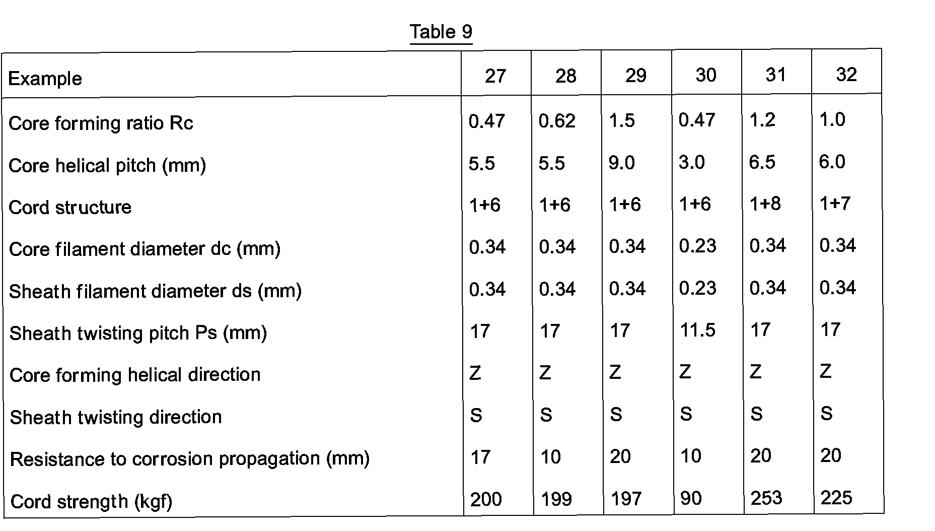
- There were prepared 32 radical tires for truck and bus of a size of 10.00 R20 having a belt in which steel cords were buried, the steel cords having core forming ratio Rc, core helical pitch Pc, cord structure, core filament diameter dc, sheath filament diameter ds, sheath twisting pitch Ps, core shaping helical direction and sheath twisting direction as shown in Tables 7 - 12.
- The resulting 32 radial tires were evaluated for resistance to corrosion propagation (separation resistance) and cord strength. The results are shown in Tables 7 - 12.
- The resistance to corrosion propagation was measured as mentioned above.
- The helical direction and sheath twisting direction (Z and S) are difined by JIS G 3510.
- The separation resistance is measured by disintegrating a pneumatic tire fitted to a car and worn completely as a result of having run a bad road and observing whether a separation at the end of belt occurred.


- In Tables 10 and 11, Comparative Examples 15 - 20 are concerned with (1+5) structure.
- Comparative Example 15 shows that the resistance to corrosion propagation was as poor as 85 mm when the core forming ratio Rc was less than 0.12.
- Comparative Example 16 shows that the cord strength was deteriorated when the core helical pitch Pc was less than 3.0 dc/0.34.
- Comparative Example 17 shows that the cord strength was deteriorated when the core forming ratio Rc was 1.0.
- Comparative Example 18 shows that the resistance to corrosion propagation was as poor as 100 mm when the core helical pitch Pc was larger than 10.0 dc/0.34.
- Comparative Example 19 shows that the resistance to corrosion propagation was as poor as 55 mm when the helical direction was the same as the sheath twisting direction.
- In Table 11, Comparative Example 20 shows that the cord strength was deteriorated when the core forming ratio Rc was larger than 1.0.
- Comparative Examples 21 - 28 are concerned with (1+6) structure.
- Comparative Example 21 shows that the resistance to corrosion propagation was as poor as 100 mm when the core forming ratio Rc was less than 0.12.
- Comparative Example 22 shows that the cord strength was deteriorated when the core helical pitch Pc was smaller than 3.0 dc/0.34.
- Comparative Example 23 shows that the cord strength was deteriorated when the core shaping ratio Rc was larger than 1.5.
- Comparative Example 24 shows that the resistance to corrosion propagation was as poor as 100 mm when the core helical pitch Pc was larger than 10.0 dc/0.34.
- In Table 12, Comparative Examples 25 and 26 are concerned with cases where no core forming was effected, and show that the resistance to corrosion resistance was deteriorated in both cases and when the sheath filament diameter was thinner, the cord strength was also lowered.
- Comparative Example 27 shows thatthe resistance to corrosion propagation was poorwhen the core forming helical direction was the same as the sheath twisting direction.
- Comparative Example 28 shows that the cord strength was deteriorated when the core forming ratio was larger 1.5 (the filament diameter was as small as 0.23 mm in both core and sheath).
- Comparative Example 29 shows that the resistance to corrosion propagation was poor when the structure was (1+7) and the core forming ratio Rc was smaller than 0.42.
- Comparative Example 30 shows that the resistance to corrosion propagation was poor when the structure was (1+8) and the core forming ratio Rc was smaller than 0.74.
- Following the procedures of Examples 1 - 16 under the conditions as shown in Tables 13 - 14, tires were prepared and the properties were tested. The results are shown in Tables 13 and 14.
- In Comparative Examples 31, 32, 37 and 38, 0 was outside of the numerical range of the present invention. In Comparative Examples 33, 34, 39 and 40, 1 was outside of the numerical range of the present invention. In Comparative Examples 35, 36, 41, and 42, G was outside of the numerical range of the present invention.
- In the above cases, separation occurred as a result of the tire running. When the tires of Examples 1 - 5 were made under the conditions of 0 = 16°, I = 0.8 mm, G = 0.6 mm and those of Examples 7 - 16 under 0 = 16°, I = 0.85 mm and G = 0.6 mm, no separation occurred.
- Following the procedures of Examples 17 - 32 under the conditions in Table 15, tires were prepared and tested. The results are shown in Table 15.
- 0 in Comparative Examples 43 and 44, I in Comparative Examples 45 and 46, and G in Comparative Examples 47 and 48 were outside of the respective numerical conditions of the present invention, and separation occurred as a result of the tire running.
- When the tires of Examples 17 - 32 were made under 0 = 16°, I = 0.85 mm and G = 0.6 mm, no separation occurred.


Claims (9)
the pitch Pc of the wave-form core steel filament being in the following range, 3.0 dc/0.34 ≦ Pc Z 10.0 dc/0.34
where dc is the diameter of the core steel filament, and the core forming ratio Rc(=Lc/dc) where dc is as defined above and Lc is an amplitude of the wave of the core steel filament being selected from the group consisting of
the pitch Pc of the helical core steel filament being in the following range,
where dc is the diameter of the core steel filament, the core forming ratio Rc(= Lc/dc)where dc is as defined above and Lc is an amplitude of the helix of the core steel filament being selected from the group consisting of
and the cross belt layer being reinforced with the steel cord of claim 1.
and the cross belt layer being reinforced with the steel cord of claim 2.
Applications Claiming Priority (12)
| Application Number | Priority Date | Filing Date | Title |
|---|---|---|---|
| JP1937592A JP3040026B2 (en) | 1992-01-09 | 1992-01-09 | Steel cord |
| JP19375/92 | 1992-01-09 | ||
| JP1937492A JP3040025B2 (en) | 1992-01-09 | 1992-01-09 | Steel cord |
| JP19374/92 | 1992-01-09 | ||
| JP19376/92 | 1992-01-09 | ||
| JP1937692A JP3040027B2 (en) | 1992-01-09 | 1992-01-09 | Steel cord |
| JP34728092A JP3359673B2 (en) | 1992-12-25 | 1992-12-25 | Pneumatic tire |
| JP347281/92 | 1992-12-25 | ||
| JP34728192A JP3359674B2 (en) | 1992-12-25 | 1992-12-25 | Pneumatic tire |
| JP34727992A JP3359672B2 (en) | 1992-12-25 | 1992-12-25 | Pneumatic tire |
| JP347279/92 | 1992-12-25 | ||
| JP347280/92 | 1992-12-25 |
Publications (3)
| Publication Number | Publication Date |
|---|---|
| EP0551124A2 true EP0551124A2 (en) | 1993-07-14 |
| EP0551124A3 EP0551124A3 (en) | 1993-12-22 |
| EP0551124B1 EP0551124B1 (en) | 1998-05-20 |
Family
ID=27548857
Family Applications (1)
| Application Number | Title | Priority Date | Filing Date |
|---|---|---|---|
| EP93100206A Expired - Lifetime EP0551124B1 (en) | 1992-01-09 | 1993-01-08 | Steel cord |
Country Status (4)
| Country | Link |
|---|---|
| US (3) | US5584169A (en) |
| EP (1) | EP0551124B1 (en) |
| DE (1) | DE69318582T2 (en) |
| ES (1) | ES2116356T3 (en) |
Cited By (11)
| Publication number | Priority date | Publication date | Assignee | Title |
|---|---|---|---|---|
| EP0676500A1 (en) * | 1994-04-07 | 1995-10-11 | N.V. Bekaert S.A. | Manufacturing steel cord with an element having a wave form |
| US5581990A (en) * | 1994-04-07 | 1996-12-10 | N.V. Bekaert S.A. | Twisting steel cord with wavy filament |
| US5606852A (en) * | 1993-04-09 | 1997-03-04 | Bridgestone Corporation | Waved-shaped, curled steel cord for reinforcing rubber articles and pneumatic radial tire using the same |
| EP0834612A1 (en) * | 1996-10-03 | 1998-04-08 | N.V. Bekaert S.A. | Steel cord with a core and a layer |
| EP0841430A1 (en) * | 1996-10-03 | 1998-05-13 | N.V. Bekaert S.A. | Steel cord with differently waved filaments |
| EP0905305A1 (en) * | 1997-09-11 | 1999-03-31 | Bridgestone Metalpha Corporation | Steel cord for reinforcing rubber product and pneumatic tyre using such steel cords |
| EP1126074A2 (en) * | 2000-02-17 | 2001-08-22 | Sumitomo Rubber Industries Limited | Pneumatic tyre |
| US6425428B1 (en) * | 1997-09-25 | 2002-07-30 | Bridgestone Corporation | Steel cord having flat side surface portion, method of manufacturing same, and pneumatic tire reinforced with same |
| US6691758B2 (en) | 1994-12-20 | 2004-02-17 | The Goodyear Tire & Rubber Company | Tires with high strength reinforcement |
| FR3059599A1 (en) * | 2016-12-07 | 2018-06-08 | Compagnie Generale Des Etablissements Michelin | PNEUMATIC COMPRISING AN OVERLAPPED REINFORCEMENT FRAME |
| WO2018104668A1 (en) * | 2016-12-07 | 2018-06-14 | Compagnie Generale Des Etablissements Michelin | Tyre with a lightened crown reinforcement |
Families Citing this family (23)
| Publication number | Priority date | Publication date | Assignee | Title |
|---|---|---|---|---|
| ES2144561T3 (en) * | 1994-11-14 | 2000-06-16 | Bridgestone Corp | STEEL CABLE TO REINFORCE A RUBBER PRODUCT. |
| FR2738813B1 (en) * | 1995-09-15 | 1997-10-17 | Saint Gobain Vitrage | SUBSTRATE WITH PHOTO-CATALYTIC COATING |
| ZA9810315B (en) * | 1997-11-27 | 1999-05-18 | Bekaert Sa Nv | Steel cord with spatially waved elements |
| JP2000177312A (en) * | 1998-12-14 | 2000-06-27 | Bridgestone Corp | Pneumatic radial tire |
| KR100680159B1 (en) | 1998-12-24 | 2007-02-08 | 피렐리 타이어 소시에떼 퍼 아찌오니 | Method And Device For Manufacturing A Metal Cord For Reinforcing Elastomeric Products, Particularly Tyres |
| AU765054B2 (en) * | 1998-12-24 | 2003-09-04 | Pirelli Pneumatici S.P.A. | Method and device for manufacturing a metal cord for reinforcing elastomeric products, particularly tyres |
| DE60027641T2 (en) * | 1999-06-23 | 2007-05-03 | Bridgestone Corp. | Steel ropes for reinforcing rubber articles, in particular pneumatic tires |
| US20040007305A1 (en) * | 2001-04-16 | 2004-01-15 | Kiyoshi Ueyoko | Pneumatic tire |
| US6748731B2 (en) * | 2002-04-08 | 2004-06-15 | Tokusen U.S.A., Inc. | Tire cord |
| DE10261538A1 (en) * | 2002-12-23 | 2004-07-01 | Thyssenkrupp Presta Ag | steering column |
| US7134098B2 (en) * | 2003-04-28 | 2006-11-07 | International Business Machines Corporation | Method, system and program product for specifying a configuration for multiple signal or dial instances in a digital system |
| AU2003251637A1 (en) * | 2003-07-25 | 2005-02-25 | Pirelli Pneumatic S.P.A. | Pneumatic tyre having a reinforced bead structure |
| KR100550287B1 (en) * | 2003-12-23 | 2006-02-08 | 홍덕스틸코드주식회사 | The steel cord made of ultra fine steel wires for carcass, and the radial tire made use of it for a passenger car |
| JP4565562B2 (en) * | 2005-09-27 | 2010-10-20 | 株式会社ブリヂストン | Pneumatic radial tire |
| ES2582192T3 (en) * | 2006-05-10 | 2016-09-09 | Nv Bekaert Sa | Metallic cable and procedure and apparatus for manufacturing a metallic cable |
| EP1900549A1 (en) * | 2006-09-15 | 2008-03-19 | NV Bekaert SA | Steel filament for cap ply reinforcement |
| CN102224292B (en) * | 2008-11-25 | 2012-08-22 | 贝卡尔特公司 | Off-the-road steel cord with crimped strands |
| CN102292222A (en) * | 2009-01-28 | 2011-12-21 | 贝卡尔特公司 | Crimped flat wire as core of oval cord |
| FR2952326B1 (en) * | 2009-11-09 | 2012-09-28 | Michelin Soc Tech | PNEUMATIC COMPRISING AT LEAST TWO BI-LAYERS |
| DE102010036809A1 (en) | 2010-07-12 | 2012-01-12 | Continental Reifen Deutschland Gmbh | Steel cord for use as a strength member in a belt ply of a pneumatic vehicle tire |
| JP5587739B2 (en) * | 2010-11-08 | 2014-09-10 | 株式会社ブリヂストン | Pneumatic tire |
| DE102017209040A1 (en) * | 2016-08-09 | 2018-02-15 | Robert Bosch Gmbh | Method for calibrating and / or operating a handheld power tool and handheld power tool |
| US11084328B2 (en) | 2018-11-29 | 2021-08-10 | The Goodyear Tire & Rubber Company | Tire reinforcement |
Citations (2)
| Publication number | Priority date | Publication date | Assignee | Title |
|---|---|---|---|---|
| JPS5614396Y2 (en) * | 1975-05-15 | 1981-04-03 | ||
| FR2476548A1 (en) * | 1980-02-21 | 1981-08-28 | Uniroyal Englebert Gmbh | REINFORCED PNEUMATIC TAPE |
Family Cites Families (21)
| Publication number | Priority date | Publication date | Assignee | Title |
|---|---|---|---|---|
| NL6717027A (en) * | 1967-02-08 | 1968-08-09 | ||
| JPS5924478B2 (en) * | 1979-07-14 | 1984-06-09 | 松下電工株式会社 | light scattering smoke detector |
| JPS58128902A (en) * | 1982-01-28 | 1983-08-01 | Toyo Tire & Rubber Co Ltd | Pneumatic tyre |
| JPS591790A (en) * | 1982-06-23 | 1984-01-07 | 金井 宏之 | Steel cord |
| JPS59125996U (en) * | 1983-02-10 | 1984-08-24 | トクセン工業株式会社 | steel cord |
| JPS6038208A (en) * | 1983-08-12 | 1985-02-27 | Toyo Tire & Rubber Co Ltd | Large-sized pneumatic tire |
| JPS6049421A (en) * | 1983-08-30 | 1985-03-18 | Fujitsu Ltd | Generating system of timing pulse |
| US4887421A (en) * | 1983-11-23 | 1989-12-19 | The Goodyear Tire & Rubber Company | Apparatus and process of manufacturing a metal cord |
| JPH0641804B2 (en) * | 1984-02-24 | 1994-06-01 | バブコツク日立株式会社 | Auxiliary steam pressure controller |
| US4566261A (en) * | 1984-09-14 | 1986-01-28 | The Goodyear Tire & Rubber Company | Metallic cable and apparatus for manufacturing the same |
| US4690191A (en) * | 1984-12-21 | 1987-09-01 | Bridgestone Corporation | Radial tire with reinforcing steel cord |
| JPS6221641A (en) * | 1985-07-19 | 1987-01-30 | Hitachi Ltd | Paper sheet handling apparatus |
| JPS63235587A (en) * | 1986-11-25 | 1988-09-30 | 横浜ゴム株式会社 | Pneumatic tire for heavy load |
| JPH01175503A (en) * | 1987-12-28 | 1989-07-12 | Bridgestone Corp | Cord-rubber complex |
| JP2936112B2 (en) * | 1988-11-11 | 1999-08-23 | 株式会社ブリヂストン | Steel cord for reinforcement |
| JPH0723591B2 (en) * | 1988-12-07 | 1995-03-15 | 株式会社ブリヂストン | Steel cord and pneumatic radial tire for reinforcing rubber articles |
| EP0462716B1 (en) * | 1990-06-16 | 1995-06-28 | Tokusen Kogyo Company Limited | Steel cord for reinforcing rubber product |
| US5285836A (en) * | 1991-01-31 | 1994-02-15 | Sumitomo Rubber Industries, Ltd. | 3+7+13 steel cord and tire including same |
| US5323595A (en) * | 1991-05-16 | 1994-06-28 | Kokoku Steel Wire Ltd. | Steel tire cord and a tire incorporating the same |
| JPH05148779A (en) * | 1991-11-28 | 1993-06-15 | Sumitomo Rubber Ind Ltd | Steel codes |
| EP0566350B1 (en) * | 1992-04-17 | 1996-01-31 | Bridgestone Corporation | Steel cords for elastomer articles and pneumatic radial tires using the same |
-
1993
- 1993-01-08 EP EP93100206A patent/EP0551124B1/en not_active Expired - Lifetime
- 1993-01-08 ES ES93100206T patent/ES2116356T3/en not_active Expired - Lifetime
- 1993-01-08 DE DE69318582T patent/DE69318582T2/en not_active Expired - Fee Related
-
1994
- 1994-11-28 US US08/348,200 patent/US5584169A/en not_active Expired - Fee Related
-
1995
- 1995-05-31 US US08/454,690 patent/US5676776A/en not_active Expired - Lifetime
-
1997
- 1997-01-08 US US08/780,452 patent/US5718783A/en not_active Expired - Lifetime
Patent Citations (3)
| Publication number | Priority date | Publication date | Assignee | Title |
|---|---|---|---|---|
| JPS5614396Y2 (en) * | 1975-05-15 | 1981-04-03 | ||
| FR2476548A1 (en) * | 1980-02-21 | 1981-08-28 | Uniroyal Englebert Gmbh | REINFORCED PNEUMATIC TAPE |
| JPS56131404A (en) * | 1980-02-21 | 1981-10-15 | Uniroyal Ag | Automobile tire |
Non-Patent Citations (2)
| Title |
|---|
| RESEARCH DISCLOSURE no. 175 , November 1978 , EMSWORTH GB pages 26 - 28 17534 'Process for the manufacture of a strand, as well as a strand made according to this process, and elastomer or synthetic material objects reinforced with such strands' * |
| RESEARCH DISCLOSURE no. 327 , July 1991 , EMSWORTH GB pages 552 - 558 327118 'Steel cord constructions made in one step' * |
Cited By (21)
| Publication number | Priority date | Publication date | Assignee | Title |
|---|---|---|---|---|
| US5606852A (en) * | 1993-04-09 | 1997-03-04 | Bridgestone Corporation | Waved-shaped, curled steel cord for reinforcing rubber articles and pneumatic radial tire using the same |
| US5581990A (en) * | 1994-04-07 | 1996-12-10 | N.V. Bekaert S.A. | Twisting steel cord with wavy filament |
| AU685587B2 (en) * | 1994-04-07 | 1998-01-22 | N.V. Bekaert S.A. | Twisting steel cord with wavy filament |
| EP0676500A1 (en) * | 1994-04-07 | 1995-10-11 | N.V. Bekaert S.A. | Manufacturing steel cord with an element having a wave form |
| US6691758B2 (en) | 1994-12-20 | 2004-02-17 | The Goodyear Tire & Rubber Company | Tires with high strength reinforcement |
| US7082978B2 (en) | 1994-12-20 | 2006-08-01 | The Goodyear Tire & Rubber Company | Tires with high strength reinforcement |
| US6857458B2 (en) | 1994-12-20 | 2005-02-22 | The Goodyear Tire & Rubber Company | Tires with high strength reinforcement |
| EP0834612A1 (en) * | 1996-10-03 | 1998-04-08 | N.V. Bekaert S.A. | Steel cord with a core and a layer |
| EP0841430A1 (en) * | 1996-10-03 | 1998-05-13 | N.V. Bekaert S.A. | Steel cord with differently waved filaments |
| US5968651A (en) * | 1996-10-03 | 1999-10-19 | N.V. Bekaert S.A. | Steel cord with differently waved filaments |
| EP0905305A1 (en) * | 1997-09-11 | 1999-03-31 | Bridgestone Metalpha Corporation | Steel cord for reinforcing rubber product and pneumatic tyre using such steel cords |
| US5911675A (en) * | 1997-09-11 | 1999-06-15 | Bridgestone Corporation | Steel cord for reinforcing rubber product and pneumatic tire using such steel cord |
| US6425428B1 (en) * | 1997-09-25 | 2002-07-30 | Bridgestone Corporation | Steel cord having flat side surface portion, method of manufacturing same, and pneumatic tire reinforced with same |
| US6612354B2 (en) | 2000-02-17 | 2003-09-02 | Sumitomo Rubber Industries, Ltd. | Pneumatic tire |
| EP1126074A3 (en) * | 2000-02-17 | 2003-04-09 | Sumitomo Rubber Industries Limited | Pneumatic tyre |
| US7066229B2 (en) | 2000-02-17 | 2006-06-27 | Sumitomo Rubber Industries, Ltd. | Pneumatic tire |
| EP1126074A2 (en) * | 2000-02-17 | 2001-08-22 | Sumitomo Rubber Industries Limited | Pneumatic tyre |
| US7316254B2 (en) | 2000-02-17 | 2008-01-08 | Sumitomo Rubber Industries, Ltd. | Pneumatic tire |
| FR3059599A1 (en) * | 2016-12-07 | 2018-06-08 | Compagnie Generale Des Etablissements Michelin | PNEUMATIC COMPRISING AN OVERLAPPED REINFORCEMENT FRAME |
| WO2018104667A1 (en) * | 2016-12-07 | 2018-06-14 | Compagnie Generale Des Etablissements Michelin | Pneumatic tyre having a more lightweight crown reinforcement |
| WO2018104668A1 (en) * | 2016-12-07 | 2018-06-14 | Compagnie Generale Des Etablissements Michelin | Tyre with a lightened crown reinforcement |
Also Published As
| Publication number | Publication date |
|---|---|
| DE69318582D1 (en) | 1998-06-25 |
| DE69318582T2 (en) | 1998-09-17 |
| US5718783A (en) | 1998-02-17 |
| EP0551124A3 (en) | 1993-12-22 |
| ES2116356T3 (en) | 1998-07-16 |
| US5676776A (en) | 1997-10-14 |
| EP0551124B1 (en) | 1998-05-20 |
| US5584169A (en) | 1996-12-17 |
Similar Documents
| Publication | Publication Date | Title |
|---|---|---|
| US5584169A (en) | Steel cord | |
| US4947638A (en) | Steel cord for reinforcing rubber | |
| EP0567334B1 (en) | Steel cords for the reinforcement of rubber articles and heavy duty pneumatic radial tires using the same | |
| US5606852A (en) | Waved-shaped, curled steel cord for reinforcing rubber articles and pneumatic radial tire using the same | |
| KR0134085B1 (en) | Pneumatic radial tires | |
| EP0387803B1 (en) | Steel cord for reinforcing rubber | |
| US5765355A (en) | Rubber article-reinforcing steel cords and pneumatic tires using such steel cords | |
| EP0372959B1 (en) | Rubber article-reinforcing steel cords and pneumatic tires using such steel cords | |
| US5213640A (en) | Rubber article-reinforcing 2+8 steel cords and pneumatic tires using such steel cords | |
| JP3469356B2 (en) | Steel cord for reinforcing rubber articles and pneumatic tire using the same | |
| JP3040026B2 (en) | Steel cord | |
| JPH11124782A (en) | Steel cord and steel radial tire | |
| EP0501720B1 (en) | Rubber article-reinforcing steel cords and pneumatic tires using such steel cords | |
| JPH061108A (en) | Pneumatic radial tire | |
| JP3464547B2 (en) | Steel cord | |
| JP3359672B2 (en) | Pneumatic tire | |
| JP3359673B2 (en) | Pneumatic tire | |
| JP3040025B2 (en) | Steel cord | |
| JPH05186979A (en) | Steel cord | |
| JPH0892883A (en) | Steel cord for reinforcing rubber article | |
| JP3359674B2 (en) | Pneumatic tire | |
| JPH08158279A (en) | Steel cord | |
| JPH08158278A (en) | Steel cord | |
| JPH08284078A (en) | Steel cord | |
| JPH08284079A (en) | Steel cord |
Legal Events
| Date | Code | Title | Description |
|---|---|---|---|
| PUAI | Public reference made under article 153(3) epc to a published international application that has entered the european phase |
Free format text: ORIGINAL CODE: 0009012 |
|
| AK | Designated contracting states |
Kind code of ref document: A2 Designated state(s): BE DE ES FR GB IT |
|
| PUAL | Search report despatched |
Free format text: ORIGINAL CODE: 0009013 |
|
| AK | Designated contracting states |
Kind code of ref document: A3 Designated state(s): BE DE ES FR GB IT |
|
| 17P | Request for examination filed |
Effective date: 19940616 |
|
| 17Q | First examination report despatched |
Effective date: 19961120 |
|
| GRAG | Despatch of communication of intention to grant |
Free format text: ORIGINAL CODE: EPIDOS AGRA |
|
| GRAG | Despatch of communication of intention to grant |
Free format text: ORIGINAL CODE: EPIDOS AGRA |
|
| GRAH | Despatch of communication of intention to grant a patent |
Free format text: ORIGINAL CODE: EPIDOS IGRA |
|
| GRAH | Despatch of communication of intention to grant a patent |
Free format text: ORIGINAL CODE: EPIDOS IGRA |
|
| GRAA | (expected) grant |
Free format text: ORIGINAL CODE: 0009210 |
|
| AK | Designated contracting states |
Kind code of ref document: B1 Designated state(s): BE DE ES FR GB IT |
|
| ITF | It: translation for a ep patent filed |
Owner name: STUDIO CIONI & PIPPARELLI |
|
| REF | Corresponds to: |
Ref document number: 69318582 Country of ref document: DE Date of ref document: 19980625 |
|
| REG | Reference to a national code |
Ref country code: ES Ref legal event code: FG2A Ref document number: 2116356 Country of ref document: ES Kind code of ref document: T3 |
|
| ET | Fr: translation filed | ||
| PLBE | No opposition filed within time limit |
Free format text: ORIGINAL CODE: 0009261 |
|
| STAA | Information on the status of an ep patent application or granted ep patent |
Free format text: STATUS: NO OPPOSITION FILED WITHIN TIME LIMIT |
|
| 26N | No opposition filed | ||
| REG | Reference to a national code |
Ref country code: GB Ref legal event code: IF02 |
|
| PGFP | Annual fee paid to national office [announced via postgrant information from national office to epo] |
Ref country code: GB Payment date: 20030108 Year of fee payment: 11 |
|
| PGFP | Annual fee paid to national office [announced via postgrant information from national office to epo] |
Ref country code: DE Payment date: 20030116 Year of fee payment: 11 |
|
| PGFP | Annual fee paid to national office [announced via postgrant information from national office to epo] |
Ref country code: ES Payment date: 20030130 Year of fee payment: 11 |
|
| PGFP | Annual fee paid to national office [announced via postgrant information from national office to epo] |
Ref country code: BE Payment date: 20030313 Year of fee payment: 11 |
|
| PG25 | Lapsed in a contracting state [announced via postgrant information from national office to epo] |
Ref country code: GB Free format text: LAPSE BECAUSE OF NON-PAYMENT OF DUE FEES Effective date: 20040108 |
|
| PG25 | Lapsed in a contracting state [announced via postgrant information from national office to epo] |
Ref country code: ES Free format text: LAPSE BECAUSE OF NON-PAYMENT OF DUE FEES Effective date: 20040109 |
|
| PG25 | Lapsed in a contracting state [announced via postgrant information from national office to epo] |
Ref country code: BE Free format text: LAPSE BECAUSE OF NON-PAYMENT OF DUE FEES Effective date: 20040131 |
|
| BERE | Be: lapsed |
Owner name: *BRIDGESTONE CORP. Effective date: 20040131 |
|
| PG25 | Lapsed in a contracting state [announced via postgrant information from national office to epo] |
Ref country code: DE Free format text: LAPSE BECAUSE OF NON-PAYMENT OF DUE FEES Effective date: 20040803 |
|
| GBPC | Gb: european patent ceased through non-payment of renewal fee |
Effective date: 20040108 |
|
| PG25 | Lapsed in a contracting state [announced via postgrant information from national office to epo] |
Ref country code: IT Free format text: LAPSE BECAUSE OF NON-PAYMENT OF DUE FEES;WARNING: LAPSES OF ITALIAN PATENTS WITH EFFECTIVE DATE BEFORE 2007 MAY HAVE OCCURRED AT ANY TIME BEFORE 2007. THE CORRECT EFFECTIVE DATE MAY BE DIFFERENT FROM THE ONE RECORDED. Effective date: 20050108 |
|
| REG | Reference to a national code |
Ref country code: ES Ref legal event code: FD2A Effective date: 20040109 |
|
| PGFP | Annual fee paid to national office [announced via postgrant information from national office to epo] |
Ref country code: FR Payment date: 20070109 Year of fee payment: 15 |
|
| REG | Reference to a national code |
Ref country code: FR Ref legal event code: ST Effective date: 20081029 |
|
| PG25 | Lapsed in a contracting state [announced via postgrant information from national office to epo] |
Ref country code: FR Free format text: LAPSE BECAUSE OF NON-PAYMENT OF DUE FEES Effective date: 20080131 |