EP0545795A1 - Cooling method and device of an internal combustion engine with highly variable load - Google Patents
Cooling method and device of an internal combustion engine with highly variable load Download PDFInfo
- Publication number
- EP0545795A1 EP0545795A1 EP92403214A EP92403214A EP0545795A1 EP 0545795 A1 EP0545795 A1 EP 0545795A1 EP 92403214 A EP92403214 A EP 92403214A EP 92403214 A EP92403214 A EP 92403214A EP 0545795 A1 EP0545795 A1 EP 0545795A1
- Authority
- EP
- European Patent Office
- Prior art keywords
- engine
- heat exchanger
- fluid
- pipe
- heat
- Prior art date
- Legal status (The legal status is an assumption and is not a legal conclusion. Google has not performed a legal analysis and makes no representation as to the accuracy of the status listed.)
- Withdrawn
Links
Images

Classifications
-
- F—MECHANICAL ENGINEERING; LIGHTING; HEATING; WEAPONS; BLASTING
- F01—MACHINES OR ENGINES IN GENERAL; ENGINE PLANTS IN GENERAL; STEAM ENGINES
- F01P—COOLING OF MACHINES OR ENGINES IN GENERAL; COOLING OF INTERNAL-COMBUSTION ENGINES
- F01P3/00—Liquid cooling
- F01P3/22—Liquid cooling characterised by evaporation and condensation of coolant in closed cycles; characterised by the coolant reaching higher temperatures than normal atmospheric boiling-point
-
- F—MECHANICAL ENGINEERING; LIGHTING; HEATING; WEAPONS; BLASTING
- F01—MACHINES OR ENGINES IN GENERAL; ENGINE PLANTS IN GENERAL; STEAM ENGINES
- F01P—COOLING OF MACHINES OR ENGINES IN GENERAL; COOLING OF INTERNAL-COMBUSTION ENGINES
- F01P7/00—Controlling of coolant flow
- F01P7/14—Controlling of coolant flow the coolant being liquid
- F01P7/16—Controlling of coolant flow the coolant being liquid by thermostatic control
-
- F—MECHANICAL ENGINEERING; LIGHTING; HEATING; WEAPONS; BLASTING
- F01—MACHINES OR ENGINES IN GENERAL; ENGINE PLANTS IN GENERAL; STEAM ENGINES
- F01P—COOLING OF MACHINES OR ENGINES IN GENERAL; COOLING OF INTERNAL-COMBUSTION ENGINES
- F01P11/00—Component parts, details, or accessories not provided for in, or of interest apart from, groups F01P1/00 - F01P9/00
- F01P11/02—Liquid-coolant filling, overflow, venting, or draining devices
- F01P11/029—Expansion reservoirs
-
- F—MECHANICAL ENGINEERING; LIGHTING; HEATING; WEAPONS; BLASTING
- F01—MACHINES OR ENGINES IN GENERAL; ENGINE PLANTS IN GENERAL; STEAM ENGINES
- F01P—COOLING OF MACHINES OR ENGINES IN GENERAL; COOLING OF INTERNAL-COMBUSTION ENGINES
- F01P3/00—Liquid cooling
- F01P3/22—Liquid cooling characterised by evaporation and condensation of coolant in closed cycles; characterised by the coolant reaching higher temperatures than normal atmospheric boiling-point
- F01P2003/2292—Liquid cooling characterised by evaporation and condensation of coolant in closed cycles; characterised by the coolant reaching higher temperatures than normal atmospheric boiling-point with thermostatically controlled by-pass
-
- F—MECHANICAL ENGINEERING; LIGHTING; HEATING; WEAPONS; BLASTING
- F01—MACHINES OR ENGINES IN GENERAL; ENGINE PLANTS IN GENERAL; STEAM ENGINES
- F01P—COOLING OF MACHINES OR ENGINES IN GENERAL; COOLING OF INTERNAL-COMBUSTION ENGINES
- F01P5/00—Pumping cooling-air or liquid coolants
- F01P5/10—Pumping liquid coolant; Arrangements of coolant pumps
- F01P5/12—Pump-driving arrangements
- F01P2005/125—Driving auxiliary pumps electrically
-
- F—MECHANICAL ENGINEERING; LIGHTING; HEATING; WEAPONS; BLASTING
- F01—MACHINES OR ENGINES IN GENERAL; ENGINE PLANTS IN GENERAL; STEAM ENGINES
- F01P—COOLING OF MACHINES OR ENGINES IN GENERAL; COOLING OF INTERNAL-COMBUSTION ENGINES
- F01P2060/00—Cooling circuits using auxiliaries
- F01P2060/04—Lubricant cooler
-
- F—MECHANICAL ENGINEERING; LIGHTING; HEATING; WEAPONS; BLASTING
- F01—MACHINES OR ENGINES IN GENERAL; ENGINE PLANTS IN GENERAL; STEAM ENGINES
- F01P—COOLING OF MACHINES OR ENGINES IN GENERAL; COOLING OF INTERNAL-COMBUSTION ENGINES
- F01P2060/00—Cooling circuits using auxiliaries
- F01P2060/08—Cabin heater
-
- F—MECHANICAL ENGINEERING; LIGHTING; HEATING; WEAPONS; BLASTING
- F01—MACHINES OR ENGINES IN GENERAL; ENGINE PLANTS IN GENERAL; STEAM ENGINES
- F01P—COOLING OF MACHINES OR ENGINES IN GENERAL; COOLING OF INTERNAL-COMBUSTION ENGINES
- F01P2060/00—Cooling circuits using auxiliaries
- F01P2060/10—Fuel manifold
-
- F—MECHANICAL ENGINEERING; LIGHTING; HEATING; WEAPONS; BLASTING
- F01—MACHINES OR ENGINES IN GENERAL; ENGINE PLANTS IN GENERAL; STEAM ENGINES
- F01P—COOLING OF MACHINES OR ENGINES IN GENERAL; COOLING OF INTERNAL-COMBUSTION ENGINES
- F01P7/00—Controlling of coolant flow
- F01P7/14—Controlling of coolant flow the coolant being liquid
- F01P7/16—Controlling of coolant flow the coolant being liquid by thermostatic control
- F01P7/167—Controlling of coolant flow the coolant being liquid by thermostatic control by adjusting the pre-set temperature according to engine parameters, e.g. engine load, engine speed
Definitions
- the invention relates to the cooling of highly variable load thermal engines, in particular motor vehicle engines.
- a usual method for cooling the heat engine of a motor vehicle consists in circulating a heat transfer fluid, such as water or an aqueous solution of an antifreeze product, between the engine which gives it heat and an exchanger heat where it gives off heat to an external environment, generally a draft of atmospheric air.
- a heat transfer fluid such as water or an aqueous solution of an antifreeze product
- the fluid is kept under pressure so as to remain practically in the liquid state, whatever the engine load and consequently the calorific flow to be evacuated, and its circulation is ensured by a pump driven mechanically by the heat engine and the flow of which is therefore proportional to the speed of rotation of the motor.
- the circulation pump consumes significant mechanical power, which can reach one to two kilowatts.
- the relative pressure of the fluid reaches 0.8 to 1.2 bar approximately, which makes it more difficult to obtain a lasting seal of the cooling circuit.
- the object of the invention is to remedy these drawbacks.
- the invention relates to a process of the kind defined in the introduction, in which the fluid is introduced into the engine in the liquid state at a volume flow rate substantially independent of the load and of the engine speed, the fluid reaching the heat exchanger entirely in the liquid state for low loads and at least partly in the gaseous state for high loads.
- This constant flow can be ensured for example by a small electric pump with a power between 30 and 100 W.
- the heat transfer fluid circulates under atmospheric pressure.
- the invention also relates to a device for implementing the method defined above, comprising a heat exchanger for extracting heat from the heat-transfer fluid, suitable for allowing the condensation of the fluid arriving in the gaseous state, an electric pump to circulate the fluid between the engine and the heat exchanger, an expansion vessel capable of accumulating a variable volume of fluid in the liquid state and in the gaseous state, and lines for the fluid connecting the engine, the heat exchanger, the pump and the expansion tank.
- the device also comprises a thermostatic valve with at least three channels, capable of varying the fraction of the fluid flow rate sent into the heat exchanger as a function of the temperature of the fluid passing through it.
- the thermostatic valve is adjustable between a first extreme position corresponding to a zero flow in the heat exchanger, which is reached for a fluid temperature below the normal operating range, in particular during start-up at engine cold, and a second extreme position corresponding to a flow rate of 100% in the heat exchanger, which is reached for a temperature of the fluid close to its boiling temperature.
- the lines can then include an engine outlet line from the engine to the heat exchanger, a return line from the heat exchanger to the thermostatic valve, an engine inlet line from the thermostatic valve to the motor and a bypass line from the outlet line to the thermostatic valve, the thermostatic valve closing the return line in its first extreme position and the bypass line in its second extreme position, and the electric pump being mounted in the line motor input.
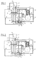
- FIGS. 1 to 3 are diagrams of a cooling device according to the invention in different operating states.
- the device illustrated is intended for cooling the heat engine 1 of a motor vehicle. It comprises an engine outlet pipe for a heat transfer fluid, formed of a first section 2 extending from an outlet orifice 3 of the engine to a connection point 4, of a second section 5 extending from the point of connection 4 to a connection point 6 located lower than the previous one, and of a third section 7 extending from the connection point 6 to an inlet 8 of a heat exchanger 9 shown diagrammatically by a simple rectangle .
- a return line 10 extends between the outlet 11 of the heat exchanger 9 and an inlet 12 of a three-way thermostatic valve 13 and has an intermediate connection point 14 placed in its lowest region.
- An engine inlet pipe comprises a first section 15 which extends from the outlet 16 of the valve 13 to an electric circulation pump 17 and has an intermediate connection point 18, and a second section 19 extending from the pump 17 to an inlet orifice 20 of the engine, a radiator 21 for heating the passenger compartment being mounted on the section 19.
- a bypass line 22 extends between the connection point 4 and a second inlet 23 of the thermostatic valve 13, the latter being located lower than the point 4.
- a degassing pipe 24 starts from a degassing orifice 25 opening into the same outlet chamber, not shown, of the heat exchanger 9 as the outlet orifice 11, and leads to an inlet opening 26 of an expansion tank 27, located at a certain height above the bottom thereof.
- the expansion tank shown only in part, is designed to receive a highly variable volume of heat transfer fluid due to the change of state thereof. It can, for this purpose, present for example a deformable wall allowing a variation of its internal volume.
- a compensation line 28 extends between an opening 29 formed in the bottom of the expansion tank 27 and the connection point 14, and is entirely located lower than the expansion tank and higher than the point 14.
- a another degassing pipe 30 starts from a connection point 31 located on the engine inlet pipe 19, between the heating radiator 21 and the engine inlet 20, and leads to an auxiliary tank 32 mounted under the bottom of the expansion tank 27 and communicating with it by a valve 33 suitable for letting air pass from the tank annexed to the expansion tank and for preventing the passage of the fluid in the liquid state between one and the other .
- the auxiliary tank 32 and the valve 33 are as described in FR-A-2 640 364, to which reference may be made for more details concerning their structure and their operation.
- On the pipe 30, which is entirely located higher than the connection point 31, is interposed a member 34 which makes it possible to transfer heat from the heat transfer fluid passing through the pipe 30 to the fuel mixture to raise its temperature before introducing it into the engine cylinders 1.
- a second compensation pipe 35 connects the annex tank 32 and the connection point 18 of the pipe 15, to which it arrives via an end region 41 situated lower than the latter.
- an oil exchanger inlet pipe 36 starts from the connection point 6, being entirely located lower than the latter and ends at a heat exchanger 37 suitable for transferring heat from the lubricating oil of the engine 1 with heat transfer fluid, called in a simplified manner "oil exchanger", and an oil exchanger outlet pipe 38 going from the exchanger 37 to a second inlet 39 of the heat exchanger 9.
- the thermostatic valve 13 has a movable element 40, shown by way of example in the form of a pivoting flap, which can move between a first extreme position illustrated in FIG. 1, where it closes the opening 12, and a second extreme position illustrated in FIG. 3, where it closes the opening 23.
- the element 40 moves as a function of the temperature of the fluid present in the valve, the position of FIG. 1 being reached for a temperature below the range of temperatures encountered in normal operation, and the position of Figure 3 being reached for a temperature equal to or slightly lower than the boiling temperature of the heat transfer fluid.
- FIG. 1 illustrates the operation of the device during the cold start of the engine 1, while the temperature of the heat transfer fluid leaving it has not reached the threshold temperature making it possible to release the inlet 12 of the thermostatic valve.
- No fluid circulates in the heat exchanger 9, nor in the lines 5, 7, 10, 36 and 38. All of the fluid circulating in the motor 1, the flow rate of which is determined by the pump 17, passes through the line bypass 22 and enters the thermostatic valve 13 through the opening 23.
- the degassing of this fluid is carried out exclusively by the pipe 30 and the auxiliary tank 32, the volume of evacuated air being compensated by the same volume of liquid returning of the reservoir 32 through the pipe 35 in the pipe 15.
- FIG. 2 The normal operation of the motor at low or medium load is illustrated in FIG. 2.
- the temperature of the fluid arriving in the thermostatic valve 13 through the opening 23 being greater than the lower threshold mentioned above, the movable element 40 releases the inlet 12 and allows the circulation of a fraction of the fluid flow rate through the heat exchanger 9.
- This fraction crossing the pipe section 5, is subdivided into a first sub-fraction entering the heat exchanger 9 via the pipe section 7 and the inlet 8, and a second sub-fraction passing through the pipe 36, the oil exchanger 37 and the pipe 38 and entering the heat exchanger 9 through the inlet 39.
- These two sub-fractions come together inside the heat exchanger 9 and the reconstituted fraction leaves it by outlet 11 and arrives at the thermostatic valve via line 10 and the opening 12.
- the other fraction complementary to the fluid passes through the bypass line 22 and the inlet 23 of the thermostatic valve as described above.
- the air possibly present in the heat exchanger 9 collects at the upper part of the outlet chamber thereof, exits therefrom the orifice 25 and reaches the expansion tank 27 via the line 24 and the inlet 26.
- a corresponding volume of fluid in the liquid state is brought back into line 10 through line 28.
- a small part of the fluid can vaporize in the engine, but it condenses before arriving at the heat exchanger 9 and to the thermostatic valve 13.
- the fluid vaporizes at least partly inside the engine and partly arrives in the gaseous state in the heat exchanger 9 which then acts as a condenser.
- the condensed fluid which emerges therefrom through the outlet 11 and reaches the thermostatic valve through the line 10 is still at a temperature close to the boiling temperature, so that the movable element 40 closes the inlet 23 and that all of the fluid flow produced by the pump 17 passes through the heat exchanger 9 for a maximum heat exchange flow.
- this heat exchange rate can be further increased, in known manner, by a fan (not shown) producing an air current through the heat exchanger 9 and controlled by a thermostatic switch as a function of the temperature of the fluid in the outlet chamber of the heat exchanger.
- the device described can be modified by placing the thermostatic valve before the heat exchanger between the outlet and the inlet of the engine.
- the bypass line then connects the thermostatic valve to the engine inlet line.
Abstract
Description
L'invention concerne le refroidissement des moteurs thermiques à charge fortement variable, en particulier des moteurs de véhicules automobiles.The invention relates to the cooling of highly variable load thermal engines, in particular motor vehicle engines.
Un procédé habituel pour le refroidissement du moteur thermique d'un véhicule automobile consiste à faire circuler un fluide caloporteur, tel que de l'eau ou une solution aqueuse d'un produit antigel, entre le moteur qui lui cède de la chaleur et un échangeur de chaleur où il cède de la chaleur à un milieu extérieur, généralement un courant d'air atmosphérique.A usual method for cooling the heat engine of a motor vehicle consists in circulating a heat transfer fluid, such as water or an aqueous solution of an antifreeze product, between the engine which gives it heat and an exchanger heat where it gives off heat to an external environment, generally a draft of atmospheric air.
Habituellement, le fluide est maintenu sous pression de façon à rester pratiquement à l'état liquide, quels que soient la charge du moteur et par conséquent le débit calorifique à évacuer, et sa circulation est assurée par une pompe entraînée mécaniquement par le moteur thermique et dont le débit est par conséquent proportionnel à la vitesse de rotation du moteur. Pour les vitesses de rotation élevées, la pompe de circulation consomme une puissance mécanique importante, pouvant atteindre un à deux kilowatts. D'autre part, la pression relative du fluide atteint O,8 à 1,2 bar environ, ce qui rend plus difficile l'obtention d'une étanchéité durable du circuit de refroidissement.Usually, the fluid is kept under pressure so as to remain practically in the liquid state, whatever the engine load and consequently the calorific flow to be evacuated, and its circulation is ensured by a pump driven mechanically by the heat engine and the flow of which is therefore proportional to the speed of rotation of the motor. For high rotational speeds, the circulation pump consumes significant mechanical power, which can reach one to two kilowatts. On the other hand, the relative pressure of the fluid reaches 0.8 to 1.2 bar approximately, which makes it more difficult to obtain a lasting seal of the cooling circuit.
Le but de l'invention est de remédier à ces inconvénients.The object of the invention is to remedy these drawbacks.
A cet effet, l'invention vise un procédé du genre défini en introduction, dans lequel on introduit le fluide dans le moteur à l'état liquide à un débit volumique sensiblement indépendant de la charge et du régime du moteur, le fluide parvenant à l'échangeur de chaleur entièrement à l'état liquide pour les faibles charges et au moins en partie à l'état gazeux pour les fortes charges.To this end, the invention relates to a process of the kind defined in the introduction, in which the fluid is introduced into the engine in the liquid state at a volume flow rate substantially independent of the load and of the engine speed, the fluid reaching the heat exchanger entirely in the liquid state for low loads and at least partly in the gaseous state for high loads.
Ce débit constant peut être assuré par exemple par une petite pompe électrique d'une puissance comprise entre 30 et 100 W.This constant flow can be ensured for example by a small electric pump with a power between 30 and 100 W.
De préférence, le fluide caloporteur circule sous la pression atmosphérique.Preferably, the heat transfer fluid circulates under atmospheric pressure.
Selon une caractéristique du procédé, lorsque le fluide caloporteur parvient à l'échangeur de chaleur entièrement à l'état liquide, une fraction du débit, variable en fonction de la charge, traverse l'échangeur de chaleur, et lorsque le fluide caloporteur parvient à l'échangeur de chaleur au moins en partie à l'état gazeux, la totalité du débit traverse l'échangeur de chaleur.According to a characteristic of the process, when the heat transfer fluid reaches the heat exchanger entirely in the liquid state, a fraction of the flow rate, which varies according to the load, passes through the heat exchanger, and when the heat transfer fluid reaches the heat exchanger at least partly in the gaseous state, the entire flow passes through the heat exchanger.
Ceci peut être réalisé en captant la température du fluide en un point déterminé du circuit et en utilisant cette information pour établir la fraction du débit à envoyer dans l'échangeur de chaleur.This can be achieved by capturing the temperature of the fluid at a specific point in the circuit and using this information to establish the fraction of the flow to be sent to the heat exchanger.
L'invention vise également un dispositif pour la mise en oeuvre du procédé défini ci-dessus, comprenant un échangeur de chaleur pour extraire de la chaleur du fluide caloporteur, propre à permettre la condensation du fluide arrivant à l'état gazeux, une pompe électrique pour faire circuler le fluide entre le moteur et l'échangeur de chaleur, un vase d'expansion propre à accumuler un volume variable de fluide à l'état liquide et à l'état gazeux, et des conduites pour le fluide reliant le moteur, l'échangeur de chaleur, la pompe et le vase d'expansion.The invention also relates to a device for implementing the method defined above, comprising a heat exchanger for extracting heat from the heat-transfer fluid, suitable for allowing the condensation of the fluid arriving in the gaseous state, an electric pump to circulate the fluid between the engine and the heat exchanger, an expansion vessel capable of accumulating a variable volume of fluid in the liquid state and in the gaseous state, and lines for the fluid connecting the engine, the heat exchanger, the pump and the expansion tank.
Avantageusement, le dispositif comprend en outre une vanne thermostatique à au moins trois voies, propre à faire varier la fraction du débit de fluide envoyée dans l'échangeur de chaleur en fonction de la température du fluide qui la traverse.Advantageously, the device also comprises a thermostatic valve with at least three channels, capable of varying the fraction of the fluid flow rate sent into the heat exchanger as a function of the temperature of the fluid passing through it.
Selon un mode de réalisation préféré, la vanne thermostatique est réglable entre une première position extrême correspondant à un débit nul dans l'échangeur de chaleur, qui est atteinte pour une température de fluide inférieure à la gamme normale de fonctionnement, notamment lors du démarrage à froid du moteur, et une seconde position extrême correspondant à un débit de 100 % dans l'échangeur de chaleur, qui est atteinte pour une température du fluide voisine de sa température d'ébullition.According to a preferred embodiment, the thermostatic valve is adjustable between a first extreme position corresponding to a zero flow in the heat exchanger, which is reached for a fluid temperature below the normal operating range, in particular during start-up at engine cold, and a second extreme position corresponding to a flow rate of 100% in the heat exchanger, which is reached for a temperature of the fluid close to its boiling temperature.
Les conduites peuvent alors comprendre une conduite de sortie du moteur allant du moteur à l'échangeur de chaleur, une conduite de retour allant de l'échangeur de chaleur à la vanne thermostatique, une conduite d'entrée du moteur allant de la vanne thermostatique au moteur et une conduite de dérivation allant de la conduite de sortie à la vanne thermostatique, la vanne thermostatique obturant la conduite de retour dans sa première position extrême et la conduite de dérivation dans sa seconde position extrême, et la pompe électrique étant montée dans la conduite d'entrée du moteur.The lines can then include an engine outlet line from the engine to the heat exchanger, a return line from the heat exchanger to the thermostatic valve, an engine inlet line from the thermostatic valve to the motor and a bypass line from the outlet line to the thermostatic valve, the thermostatic valve closing the return line in its first extreme position and the bypass line in its second extreme position, and the electric pump being mounted in the line motor input.
On peut prévoir en outre tout ou partie des conduites suivantes :
- une première conduite de dégazage allant d'une chambre de sortie de l'échangeur de chaleur au vase d'expansion et située plus haut que celle-ci ;
- une première conduite de compensation allant d'une région inférieure du vase d'expansion, toujours remplie de fluide à l'état liquide, à la conduite de retour ;
- une seconde conduite de dégazage allant de la conduite d'entrée du moteur à un réservoir annexe situé plus bas que le vase d'expansion et reliée à celui-ci à travers un clapet propre à laisser passer l'air du réservoir annexe au vase d'expansion et à interdire le passage du liquide entre l'un et l'autre, la seconde conduite de dégazage étant située plus haut que la conduite d'entrée du moteur ;
- une seconde conduite de compensation partant du réservoir annexe et arrivant à la conduite d'entrée du moteur par une portion terminale située au-dessous de celle-ci ;
- une conduite d'entrée d'échangeur à huile partant de la conduite de sortie du moteur, en aval du point de départ de la conduite de dérivation, et située plus bas que la conduite de sortie du moteur, et allant à un échangeur à huile dans lequel de l'huile de lubrification du moteur peut céder de la chaleur au fluide caloporteur ; et
- une conduite de sortie d'échangeur à huile allant de l'échangeur à huile à l'échangeur de chaleur.
- a first degassing pipe going from an outlet chamber of the heat exchanger to the expansion tank and situated higher than the latter;
- a first compensation pipe going from a lower region of the expansion tank, always filled with fluid in the liquid state, to the return pipe;
- a second degassing pipe running from the engine inlet pipe to an auxiliary tank located lower than the expansion tank and connected to the latter through a valve suitable for letting air pass from the auxiliary tank to the tank d expansion and prohibiting the passage of the liquid between them, the second degassing pipe being located higher than the engine inlet pipe;
- a second compensation pipe starting from the annex tank and arriving at the engine inlet pipe by an end portion situated below the latter;
- an oil exchanger inlet pipe starting from the engine outlet pipe, downstream from the starting point of the bypass line, and located lower than the engine outlet line, and going to an oil exchanger in which engine lubricating oil can transfer heat to the heat transfer fluid; and
- an oil exchanger outlet pipe going from the oil exchanger to the heat exchanger.
D'autres caractéristiques et avantages de l'invention ressortiront de la description détaillée donnée ci-après d'un exemple de réalisation, et des dessins annexés dans lesquels les figures 1 à 3 sont des schémas d'un dispositif de refroidissement selon l'invention dans des états de fonctionnement différents.Other characteristics and advantages of the invention will emerge from the detailed description given below of an exemplary embodiment, and from the appended drawings in which FIGS. 1 to 3 are diagrams of a cooling device according to the invention in different operating states.
Le dispositif illustré est destiné au refroidissement du moteur thermique 1 d'un véhicule automobile. Il comprend une conduite de sortie du moteur pour un fluide caloporteur, formé d'un premier tronçon 2 s'étendant d'un orifice de sortie 3 du moteur à un point de raccordement 4, d'un second tronçon 5 s'étendant du point de raccordement 4 à un point de raccordement 6 situé plus bas que le précédent, et d'un troisième tronçon 7 s'étendant du point de raccordement 6 à une entrée 8 d'un échangeur de chaleur 9 représenté de façon schématique par un simple rectangle. Une conduite de retour 10 s'étend entre la sortie 11 de l'échangeur de chaleur 9 et une entrée 12 d'une vanne thermostatique à trois voies 13 et comporte un point de raccordement intermédiaire 14 placé dans sa région la plus basse. Une conduite d'entrée du moteur comprend un premier tronçon 15 qui s'étend de la sortie 16 de la vanne 13 à une pompe électrique de circulation 17 et présente un point de raccordement intermédiaire 18, et un second tronçon 19 s'étendant de la pompe 17 à un orifice d'entrée 20 du moteur, un radiateur 21 de chauffage de l'habitacle étant monté sur le tronçon 19.The device illustrated is intended for cooling the
Une conduite de dérivation 22 s'étend entre le point de raccordement 4 et une seconde entrée 23 de la vanne thermostatique 13, cette dernière étant située plus bas que le point 4.A
Une conduite de dégazage 24 part d'un orifice de dégazage 25 débouchant dans la même chambre de sortie, non représentée, de l'échangeur de chaleur 9 que l'orifice de sortie 11, et aboutit à une ouverture d'entrée 26 d'un vase d'expansion 27, située à une certaine hauteur au-dessus du fond de celui-ci. Le vase d'expansion, représenté seulement en partie, est prévu pour recevoir un volume fortement variable de fluide caloporteur en raison du changement d'état de celui-ci. Il peut, à cet effet, présenter par exemple une paroi déformable permettant une variation de son volume interne. Une conduite de compensation 28 s'étend entre une ouverture 29 ménagée dans le fond du vase d'expansion 27 et le point de raccordement 14, et est entièrement située plus bas que le vase d'expansion et plus haut que le point 14. Une autre conduite de dégazage 30 part d'un point de raccordement 31 situé sur la conduite d'entrée du moteur 19, entre le radiateur de chauffage 21 et l'entrée 20 du moteur, et aboutit à un réservoir annexe 32 monté sous le fond du vase d'expansion 27 et communiquant avec celui-ci par un clapet 33 propre à laisser passer l'air du réservoir annexe au vase d'expansion et à interdire le passage du fluide à l'état liquide entre l'un et l'autre. Le réservoir annexe 32 et le clapet 33 sont tels que décrits dans FR-A-2 640 364, auquel on pourra se reporter pour plus de détails concernant leur structure et leur fonctionnement. Sur la conduite 30, qui est entièrement située plus haut que le point de raccordement 31, est interposé un organe 34 qui permet de transférer de la chaleur du fluide caloporteur traversant la conduite 30 au mélange combustible pour élever sa température avant de l'introduire dans les cylindres du moteur 1. Une seconde conduite de compensation 35 relie le réservoir annexe 32 et le point de raccordement 18 de la conduite 15, auquel elle arrive par une région terminale 41 située plus bas que celui-ci.A
Enfin, une conduite d'entrée d'échangeur à huile 36 part du point de raccordement 6 en étant entièrement située plus bas que celui-ci et aboutit à un échangeur de chaleur 37 propre à transférer de la chaleur de l'huile de lubrification du moteur 1 au fluide caloporteur, appelé de manière simplifié "échangeur à huile", et une conduite de sortie d'échangeur à huile 38 allant de l'échangeur 37 à une seconde entrée 39 de l'échangeur de chaleur 9.Finally, an oil
La vanne thermostatique 13 présente un élément mobile 40, représenté à titre d'exemple sous la forme d'un volet pivotant, qui peut se déplacer entre une première position extrême illustrée à la figure 1, où il obture l'ouverture 12, et une seconde position extrême illustrée à la figure 3, où il obture l'ouverture 23. L'élément 40 se déplace en fonction de la température du fluide présent dans la vanne, la position de la figure 1 étant atteinte pour une température inférieure au domaine des températures rencontrées en fonctionnement normal, et la position de la figure 3 étant atteinte pour une température égale ou légèrement inférieure à la température d'ébullition du fluide caloporteur.The thermostatic valve 13 has a
La figure 1 illustre le fonctionnement du dispositif lors du démarrage à froid du moteur 1, alors que la température du fluide caloporteur sortant de celui-ci n'a pas atteint la température de seuil permettant de libérer l'entrée 12 de la vanne thermostatique. Aucun fluide ne circule dans l'échangeur de chaleur 9, ni dans les conduites 5, 7, 10, 36 et 38. La totalité du fluide circulant dans le moteur 1, dont le débit est déterminé par la pompe 17, passe par la conduite de dérivation 22 et pénètre dans la vanne thermostatique 13 par l'ouverture 23. Le dégazage de ce fluide s'effectue exclusivement par la conduite 30 et le réservoir annexe 32, le volume d'air évacué étant compensé par un même volume de liquide revenant du réservoir 32 par la conduite 35 dans la conduite 15.FIG. 1 illustrates the operation of the device during the cold start of the
Le fonctionnement normal du moteur à charge faible ou moyenne est illustré à la figure 2. La température du fluide parvenant dans la vanne thermostatique 13 par l'ouverture 23 étant supérieure au seuil inférieur mentionné ci-dessus, l'élément mobile 40 libère l'entrée 12 et permet la circulation d'une fraction du débit du fluide à travers l'échangeur de chaleur 9. Cette fraction, traversant le tronçon de conduite 5, se subdivise en une première sous-fraction pénétrant dans l'échangeur de chaleur 9 par le tronçon de conduite 7 et l'entrée 8, et une seconde sous-fraction traversant la conduite 36, l'échangeur à huile 37 et la conduite 38 et pénétrant dans l'échangeur de chaleur 9 par l'entrée 39. Ces deux sous-fractions se rejoignent à l'intérieur de l'échangeur de chaleur 9 et la fraction reconstituée sort de celui-ci par la sortie 11 et arrive à la vanne thermostatique par la conduite 10 et l'ouverture 12. L'autre fraction complémentaire du fluide passe par la conduite de dérivation 22 et l'entrée 23 de la vanne thermostatique comme décrit précédemment. L'air éventuellement présent dans l'échangeur de chaleur 9 se rassemble à la partie supérieure de la chambre de sortie de celui-ci, en sort par l'orifice 25 et parvient au vase d'expansion 27 par la conduite 24 et l'entrée 26. Un volume correspondant de fluide à l'état liquide est ramené dans la conduite 10 par la conduite 28. Une petite partie du fluide peut se vaporiser dans le moteur, mais elle se condense avant d'arriver à l'échangeur de chaleur 9 et à la vanne thermostatique 13.The normal operation of the motor at low or medium load is illustrated in FIG. 2. The temperature of the fluid arriving in the thermostatic valve 13 through the opening 23 being greater than the lower threshold mentioned above, the
Pour les charges les plus élevées du moteur, le fluide se vaporise au moins en partie à l'intérieur du moteur et arrive en partie à l'état gazeux dans l'échangeur de chaleur 9 qui joue alors le rôle de condenseur. Le fluide condensé qui en ressort par la sortie 11 et parvient à la vanne thermostatique par la conduite 10 est encore à une température voisine de la température d'ébullition, de sorte que l'élément mobile 40 obture l'entrée 23 et que la totalité du débit de fluide produit par la pompe 17 traverse l'échangeur de chaleur 9 pour un débit d'échange de chaleur maximal. Bien entendu, ce débit d'échange de chaleur peut être encore accru, de façon connue, par un ventilateur non représenté produisant un courant d'air à travers l'échangeur de chaleur 9 et commandé par un interrupteur thermostatique en fonction de la température du fluide dans la chambre de sortie de l'échangeur de chaleur.For the higher engine loads, the fluid vaporizes at least partly inside the engine and partly arrives in the gaseous state in the
Le dispositif décrit peut être modifié en plaçant la vanne thermostatique avant l'échangeur de chaleur entre la sortie et l'entrée du moteur. La conduite de dérivation relie alors la vanne thermostatique à la conduite d'entrée du moteur.The device described can be modified by placing the thermostatic valve before the heat exchanger between the outlet and the inlet of the engine. The bypass line then connects the thermostatic valve to the engine inlet line.
Claims (11)
Applications Claiming Priority (2)
| Application Number | Priority Date | Filing Date | Title |
|---|---|---|---|
| FR9115173 | 1991-12-06 | ||
| FR9115173A FR2684721A1 (en) | 1991-12-06 | 1991-12-06 | METHOD AND APPARATUS FOR COOLING A HEAVY - VARIABLE CHARGE THERMAL MOTOR. |
Publications (1)
| Publication Number | Publication Date |
|---|---|
| EP0545795A1 true EP0545795A1 (en) | 1993-06-09 |
Family
ID=9419771
Family Applications (1)
| Application Number | Title | Priority Date | Filing Date |
|---|---|---|---|
| EP92403214A Withdrawn EP0545795A1 (en) | 1991-12-06 | 1992-11-27 | Cooling method and device of an internal combustion engine with highly variable load |
Country Status (4)
| Country | Link |
|---|---|
| US (1) | US5309870A (en) |
| EP (1) | EP0545795A1 (en) |
| JP (1) | JPH0617649A (en) |
| FR (1) | FR2684721A1 (en) |
Cited By (5)
| Publication number | Priority date | Publication date | Assignee | Title |
|---|---|---|---|---|
| DE4342293A1 (en) * | 1993-12-11 | 1995-06-14 | Bayerische Motoren Werke Ag | Cooling system for IC engine |
| DE4342294A1 (en) * | 1993-02-12 | 1995-06-14 | Bayerische Motoren Werke Ag | Fluid cooling system for IC engine |
| DE4342292A1 (en) * | 1993-12-11 | 1995-06-14 | Bayerische Motoren Werke Ag | Partly flooded vaporised cooling system for IC engine |
| CN103363148A (en) * | 2012-03-30 | 2013-10-23 | 福特环球技术公司 | Variable flow resistance |
| CN104865074A (en) * | 2015-05-29 | 2015-08-26 | 安徽江淮汽车股份有限公司 | Water constant temperature device for engine test |
Families Citing this family (9)
| Publication number | Priority date | Publication date | Assignee | Title |
|---|---|---|---|---|
| US5699759A (en) * | 1995-12-21 | 1997-12-23 | Thomas J. Hollis | Free-flow buoyancy check valve for controlling flow of temperature control fluid from an overflow bottle |
| SE521618C2 (en) * | 1998-07-31 | 2003-11-18 | Volvo Lastvagnar Ab | Method and apparatus for venting a coolant system to an internal combustion engine |
| CA2474415A1 (en) * | 2004-07-15 | 2006-01-15 | Gerald Hayes | Auxillary cooler for an engine located in a building |
| SE529541C2 (en) * | 2005-12-05 | 2007-09-11 | Volvo Lastvagnar Ab | Cooling |
| US7748211B2 (en) * | 2006-12-19 | 2010-07-06 | United Technologies Corporation | Vapor cooling of detonation engines |
| US8056345B2 (en) | 2007-06-13 | 2011-11-15 | United Technologies Corporation | Hybrid cooling of a gas turbine engine |
| EP2843222B1 (en) * | 2012-04-23 | 2020-07-29 | Toyota Jidosha Kabushiki Kaisha | Heat transport device |
| GB2530736B (en) * | 2014-09-30 | 2020-04-15 | Ford Global Tech Llc | Engine cooling system |
| DE102021200549A1 (en) | 2021-01-21 | 2022-07-21 | Psa Automobiles Sa | Method for controlling a cooling system for cooling at least one component to be cooled and device for carrying out the method |
Citations (5)
| Publication number | Priority date | Publication date | Assignee | Title |
|---|---|---|---|---|
| US1767598A (en) * | 1921-07-22 | 1930-06-24 | Sue R Mallory | Engine-cooling system |
| US4550694A (en) * | 1984-05-11 | 1985-11-05 | Evans Cooling Associates | Process and apparatus for cooling internal combustion engines |
| EP0207354A2 (en) * | 1985-07-05 | 1987-01-07 | Nissan Motor Co., Ltd. | Method and system for cooling automotive engines |
| US4768484A (en) * | 1987-07-13 | 1988-09-06 | General Motors Corporation | Actively pressurized engine cooling system |
| DE3809136A1 (en) * | 1987-04-02 | 1988-10-13 | Volkswagen Ag | Device for the evaporation cooling of an internal combustion engine and operation of a heating heat exchanger by means of the coolant |
Family Cites Families (1)
| Publication number | Priority date | Publication date | Assignee | Title |
|---|---|---|---|---|
| JPS6093113A (en) * | 1983-10-28 | 1985-05-24 | Nissan Motor Co Ltd | Boiling and cooling device for engine |
-
1991
- 1991-12-06 FR FR9115173A patent/FR2684721A1/en active Granted
-
1992
- 1992-11-27 EP EP92403214A patent/EP0545795A1/en not_active Withdrawn
- 1992-12-04 US US07/986,138 patent/US5309870A/en not_active Expired - Fee Related
- 1992-12-04 JP JP4350181A patent/JPH0617649A/en active Pending
Patent Citations (5)
| Publication number | Priority date | Publication date | Assignee | Title |
|---|---|---|---|---|
| US1767598A (en) * | 1921-07-22 | 1930-06-24 | Sue R Mallory | Engine-cooling system |
| US4550694A (en) * | 1984-05-11 | 1985-11-05 | Evans Cooling Associates | Process and apparatus for cooling internal combustion engines |
| EP0207354A2 (en) * | 1985-07-05 | 1987-01-07 | Nissan Motor Co., Ltd. | Method and system for cooling automotive engines |
| DE3809136A1 (en) * | 1987-04-02 | 1988-10-13 | Volkswagen Ag | Device for the evaporation cooling of an internal combustion engine and operation of a heating heat exchanger by means of the coolant |
| US4768484A (en) * | 1987-07-13 | 1988-09-06 | General Motors Corporation | Actively pressurized engine cooling system |
Cited By (5)
| Publication number | Priority date | Publication date | Assignee | Title |
|---|---|---|---|---|
| DE4342294A1 (en) * | 1993-02-12 | 1995-06-14 | Bayerische Motoren Werke Ag | Fluid cooling system for IC engine |
| DE4342293A1 (en) * | 1993-12-11 | 1995-06-14 | Bayerische Motoren Werke Ag | Cooling system for IC engine |
| DE4342292A1 (en) * | 1993-12-11 | 1995-06-14 | Bayerische Motoren Werke Ag | Partly flooded vaporised cooling system for IC engine |
| CN103363148A (en) * | 2012-03-30 | 2013-10-23 | 福特环球技术公司 | Variable flow resistance |
| CN104865074A (en) * | 2015-05-29 | 2015-08-26 | 安徽江淮汽车股份有限公司 | Water constant temperature device for engine test |
Also Published As
| Publication number | Publication date |
|---|---|
| US5309870A (en) | 1994-05-10 |
| FR2684721A1 (en) | 1993-06-11 |
| JPH0617649A (en) | 1994-01-25 |
| FR2684721B1 (en) | 1995-04-21 |
Similar Documents
| Publication | Publication Date | Title |
|---|---|---|
| EP0545795A1 (en) | Cooling method and device of an internal combustion engine with highly variable load | |
| FR2809451A1 (en) | HEAT ENGINE WITH COOLING CIRCUIT AND HEAT EXCHANGER, CONNECTED TO SAME | |
| EP0197823A1 (en) | Heat exchanger for a motor vehicle, particularly of the type for exhaust gases | |
| FR2642012A1 (en) | DEVICE FOR HEATING AUTOMOTIVE VEHICLES EQUIPPED WITH AN INTERNAL COMBUSTION ENGINE, IN PARTICULAR BUS | |
| FR2792259A1 (en) | Cooling system for electric vehicle with fuel cell, comprises a first fuel cell cooling loop using deionized water, a heat exchanger and a second motor cooling loop using water and antifreeze | |
| FR2796337A1 (en) | HEAT-AIR CONDITIONING SYSTEM FOR MOTOR VEHICLE | |
| FR2745033A1 (en) | COOLING SYSTEM FOR AN INTERNAL COMBUSTION ENGINE | |
| FR2949642A1 (en) | ELECTRIC POWER CONVERTER FOR A RAILWAY VEHICLE | |
| FR2782676A1 (en) | INTEGRATED HEATING SYSTEM IN THE COLD CIRCUIT | |
| FR2928867A1 (en) | DEVICE AND METHOD FOR HEATING A VEHICLE OF A MOTOR VEHICLE, ESPECIALLY AN ELECTRIC VEHICLE. | |
| FR2482906A1 (en) | IMPROVEMENTS IN COOLING SYSTEMS OF MOTORS OF RADIATOR VEHICLES ASSOCIATED WITH AN EXPANSION TANK | |
| EP2126308A1 (en) | System and method for cooling the propulsion unit of an automobile | |
| EP0986706B1 (en) | System for vaporising liquefied petrol gas heated by engine lubricating oil | |
| FR2976322A1 (en) | Air distributor for combustion engine of heat transfer system in car, has two U-shaped heat exchangers connected in series with respect to charging air and traversed by coolant having specified temperature at inlets of exchangers | |
| EP2758647B1 (en) | Cooling of an electric motor via heat pipes | |
| EP2110536A1 (en) | Exhaust manifold integrated in the cylinder head of an engine of a vehicle | |
| EP1902877A1 (en) | Method of thermal management, in particular for cooling an engine and/or for the air conditioning of an automobile and thermal management system using such a method | |
| FR2800017A1 (en) | Cooling circuit for electrical motor of hydrogen source combustible battery driven vehicle, uses inert cooling fluid having electrical insulating properties | |
| WO2008116992A1 (en) | System and method for cooling a motor propulsion unit on a motor vehicle | |
| WO1982004474A1 (en) | Process and device for producing domestic hot water from the heat power wasted in cooling down vehicle engines | |
| FR2610989A1 (en) | AUXILIARY COOLING CIRCUIT FOR MOTOR VEHICLE | |
| FR2752016A1 (en) | Cooling system for internal combustion engine | |
| FR2691504A1 (en) | Cooling device for a heat engine comprising a condenser. | |
| EP0850791B1 (en) | Heating system for the passenger compartment of a diesel combustion engine motor vehicle | |
| EP0767081B1 (en) | Device for the recovery of heat from the exhaust gases of a vehicle |
Legal Events
| Date | Code | Title | Description |
|---|---|---|---|
| PUAI | Public reference made under article 153(3) epc to a published international application that has entered the european phase |
Free format text: ORIGINAL CODE: 0009012 |
|
| AK | Designated contracting states |
Kind code of ref document: A1 Designated state(s): DE ES GB IT |
|
| 17P | Request for examination filed |
Effective date: 19930914 |
|
| 17Q | First examination report despatched |
Effective date: 19940929 |
|
| STAA | Information on the status of an ep patent application or granted ep patent |
Free format text: STATUS: THE APPLICATION IS DEEMED TO BE WITHDRAWN |
|
| 18D | Application deemed to be withdrawn |
Effective date: 19950210 |