EP0545734A2 - Halftoning with error feedback and image dependent enhancement - Google Patents
Halftoning with error feedback and image dependent enhancement Download PDFInfo
- Publication number
- EP0545734A2 EP0545734A2 EP92311106A EP92311106A EP0545734A2 EP 0545734 A2 EP0545734 A2 EP 0545734A2 EP 92311106 A EP92311106 A EP 92311106A EP 92311106 A EP92311106 A EP 92311106A EP 0545734 A2 EP0545734 A2 EP 0545734A2
- Authority
- EP
- European Patent Office
- Prior art keywords
- value
- gray
- input
- image
- optical density
- Prior art date
- Legal status (The legal status is an assumption and is not a legal conclusion. Google has not performed a legal analysis and makes no representation as to the accuracy of the status listed.)
- Granted
Links
Images

Classifications
-
- H—ELECTRICITY
- H04—ELECTRIC COMMUNICATION TECHNIQUE
- H04N—PICTORIAL COMMUNICATION, e.g. TELEVISION
- H04N1/00—Scanning, transmission or reproduction of documents or the like, e.g. facsimile transmission; Details thereof
- H04N1/40—Picture signal circuits
- H04N1/405—Halftoning, i.e. converting the picture signal of a continuous-tone original into a corresponding signal showing only two levels
- H04N1/4051—Halftoning, i.e. converting the picture signal of a continuous-tone original into a corresponding signal showing only two levels producing a dispersed dots halftone pattern, the dots having substantially the same size
- H04N1/4052—Halftoning, i.e. converting the picture signal of a continuous-tone original into a corresponding signal showing only two levels producing a dispersed dots halftone pattern, the dots having substantially the same size by error diffusion, i.e. transferring the binarising error to neighbouring dot decisions
- H04N1/4053—Halftoning, i.e. converting the picture signal of a continuous-tone original into a corresponding signal showing only two levels producing a dispersed dots halftone pattern, the dots having substantially the same size by error diffusion, i.e. transferring the binarising error to neighbouring dot decisions with threshold modulated relative to input image data or vice versa
Definitions
- This invention relates to digital halftoning, combining a specific method of halftoning, which determine the best fit halftone screen, and an error diffusion scheme.
- Image information is commonly generated in a bitmap format where the bitmap comprises a plurality of gray level pixels, i.e. pixels that are defined by digital values, each value representing a gray level among a number of gray levels.
- bitmap comprises a plurality of gray level pixels, i.e. pixels that are defined by digital values, each value representing a gray level among a number of gray levels.
- 256 levels of gray are present, where each level represents an increment of gray between black and white.
- color bitmaps where three defining colors or separations each include 256 levels of information, there may be more than 16 million colors defined by a gray bitmap.
- bitmaps in such a gray level format are unprintable by standard printers.
- Standard printers print in a limited number of levels, either a spot or a no spot in the binary case, or a limited number of levels associated with the spot, for example, four in the quaternary case. Accordingly, it is necessary to reduce the gray level image data to a limited number of levels so that it is printed.
- One standard method of converting gray level pixel values to binary level pixel values is through the use of dithering or halftoning processes.
- each pixel value of an array of gray level pixels within the area is compared to one of a set of preselected thresholds (the thresholds are stored as a dither matrix and the repetitive pattern generated by this matrix is considered a halftone cell) as taught, for example, in US-A 4,149,194 to Holladay.
- the effect of such an arrangement is that, for an area where the image is gray, some of the thresholds within the dither matrix will be exceeded, i.e.
- the image value at that specific location is larger than the value stored in the dither matrix for that same location, while others are not.
- the pixels or cell elements for which the thresholds are exceeded might be printed as black, while the remaining elements are allowed to remain white, dependent on the actual physical quantity described by the data.
- the effect of the distribution of black and white over the halftone cell is integrated by the human eye as gray. Dithering or halftoning presents problems, however, in that the amount of gray within an original image is not maintained exactly over an area, because the finite number of elements inside each dither matrix - and therefore halftone cell - only allows the reproduction of a finite number of gray levels, i.e. number of elements in the cell plus one, or less.
- image information initially has a set of halftone screen values for a cell added to the information.
- Error diffusion attempts to maintain gray by making the conversion from gray pixels to binary or other level pixels on a pixel-by-pixel basis.
- the procedure examines each pixel with respect to a threshold, and the difference between the gray level pixel value and the output value is forwarded to a selected group or set of neighboring pixels, in accordance with a weighting scheme.
- a problem noted with the use of the standard error diffusion algorithms for printing applications is the production of large numbers of isolated black and/or white pixels which are non-printable by many types of printers.
- 253-258 shows a dither matrix used as a threshold for error diffusion, to alleviate the problems of undesired patterns generally produced by the error diffusion algorithm.
- a method to overcome the printability problem is taught by US-A 4,654,721 to Goertzel, where a method is shown to convert a continuous tone image to a bilevel pixel image. The total error generated in one halftone cell is distributed to a predetermined number of adjacent halftone cells. In this way, printable images are generated, while the banding artifact is reduced, by alternating between fixed output cell patterns. Because of an inherent lack of partial dots in this process, evidenced as a loss in sharpness, edge detection and sharpening was included.
- a method for quantizing gray level pixels using a combination of halftoning and error diffusion which initially determines a best fit halftone cell, and propagates halftoning error in order to maintain gray density.
- 'c' and 'd' are integer values representing pixel depth.
- the value of gray in a portion of the input image corresponding to a halftone cell is integrated to produce an average input gray value.
- An error value is added to each pixel in the original image, that belongs to a current halftone cell, from processing of previous pixels in the image, belonging to a predetermined set of previously processed halftone cells, in accordance with the method, to produce a modified input value, for each pixel of the current halftone cell.
- a screen value is added, from a set of stored screen values to generate a screened modified input value.
- the screened modified input value is compared to a threshold value, to produce an output which is one of a desired output set of values.
- the value of the gray level of the output image in the portion of the output image corresponding to a halftone cell is integrated to produce an average output gray value.
- the average output gray value is compared to the average modified input gray value, to determine a input/output difference.
- the input/output difference controls the threshold value, so that the threshold is set to attempt maintain gray density equal between the input image and the output image.
- an error is calculated between the average gray value of the original image and the average gray value of the output image and preselected fractions thereof are forwarded to unprocessed pixels belonging to a preselected set of unprocessed halftone cells.
- the average modified input gray value is represented by the average output gray value with an deviation of not more than 0.5 of one level over the full halftone cell, e.g.: for the simple example of a binary output, using a halftone cell of 2 by 2, five average output levels can be reproduced, i.e. 0, 0.25, 0.5, 0.75 and 1.
- the maximum deviation over this cell will be 0.5x0.25 (half of one level). Note, that standard halftoning procedures do not guarantee this maximum deviation, i.e. an average input gray level of 0.6 might be represented by an average output gray level of 0.75, dependent on the spatial detail of the input.
- the average gray value of the modified image may be compared to the average gray value of the output image.
- the error is forwarded, not to a preselected set of pixels, but to a buffer that is used in updating the average gray value calculation over one halftone cell for a preselected number of subsequent halftone cells.
- gray level image data from image input 10 may be characterized as image data, each pixel of which is defined at a single level or optical density in a set of 'c' optical density levels, the number of members in the set of levels being larger than desired.
- Each pixel will be processed in the manner described hereinbelow, to redefine each pixel in terms of a new, smaller set of 'd' levels.
- 'c' and 'd' are integer values representing pixel depth.
- color data may be represented by a number of independent channels which are handled independently, or the color data might be represented as vector data in a predefined color space, e.g.: RGB, CIELab etc., being submitted to vector operations in the thresholding,error calculation and correction.
- RGB Red, green and blue
- cyan magenta, yellow and black
- An input image of the type to be processed as hereinafter described may be represented by a set of gray values (gray level pixels) arranged in an array of L lines, each line containing N gray values with depth b, with any one pixel in said array denoted by I(n,l).
- Gray values are typically expressed as integers, with one example falling in the range from 0 to 255, although greater or lesser number of levels, as well as non-integer representations, are possible.
- An output image is considered to consist of pixels, each pixel corresponding to an output element that is printed by a digital printer or display.
- image I(n,l) is received at image buffer 100, holding the information of one halftone cell.
- a halftone screen, S(n,l), a set of values stored in halftone memory 106, is added to each pixel value of I(n,l), to impose a periodic function thereon.
- the halftone screen may be the same screen for the whole image, but multiple screens may be used, with selection of the screen depending upon the current image data.
- adjustable threshold 108 a threshold is applied to the image, now representable as the signal I(n,l)+S(n,l), where the threshold is adjustable from halftone cell to halftone cell, as will be further described, in accordance with the ARIES method of halftoning.
- halftoning has been described for simplicity as the addition of a set of selected screen values to pixel values within a defined area of the image, in conjunction with a uniform application of a threshold level(s) to the combined values, it will be understood that the process of halftoning may also be represented by a set of varying thresholds defined at locations corresponding to pixels over a given area of the image.
- a halftone cell as used herein, is generally smaller than the total image and will be replicated in a predetermined scheme in order to cover an area of the image.
- a method for an efficient representation of variable angle halftone cells by a dither matrix and a corresponding replication scheme is given in US-A 4,149,194 to Holladay.
- the output of a process using a dither matrix is a set of pixel values, having a number of members less than the input set of values.
- the set of output values is binary, either black or white, or a spot or no spot, although the values might be gray as described in EP-A-000,000, corresponding to United States Patent Application Ser. No. 07/583,337 by Shiau.
- the binary output of a single halftone cell is a set of pixels that are either black or white which together form a "dot".
- Single pixels, black or white, surrounded respectively by white or black pixels, are difficult to print with electrophotographic devices. For this reason, standard dither matrices for electrophotographic applications tend to cluster pixels together, with growth pattern that begins in a central area of the halftone cell and grows as more elements of the cell are black. Such a dot pattern is printable on electrophotographic devices.
- adjustable threshold 108 The output of adjustable threshold 108, the signal B(n,l) which in a binary system is a set of binary, or black and white pixels, is stored to output buffer 110, from which it can be directed to an output device.
- Signal B(n,l) is also integrated to provide an average gray output value over a halftone cell at block 111, and the average gray output value is directed to comparator 112 (DO GRAYS MATCH) to be compared with the average gray input value of the input image over the halftone cell, generated at integrator 113 and corrected by error from previous cells added to the average gray value at adder 114 (as will be described further below).
- Comparator 112 adjusts variable threshold 108 to minimize the deviation between I(n,l) and B(n,l) over the halftone cell.
- Error determination block 117 calculates a difference between the average gray input value generated at integrator 113 and average gray output value output generated at integrator 111. This gray value error is passed to error fraction determination block 116 where the fractional error values are calculated and passed to the error term buffer 115 to be used in the processing of subsequent halftone cells.
- Figure 2 shows one such fractional error distribution, in which for each unprocessed halftone cell identified in a neighborhood of the current halftone cell identified by *, a fractional error value, equal to the error ⁇ , multiplied by a coefficient corresponding to the halftone cell position in the neighborhood with respect to the halftone cell from which ⁇ is derived, and the factor 1/48, will be added to a subsequent halftone cell.
- any particular halftone cell is a member of the neighborhoods of several halftone cells and accordingly, a final error term that is added to the halftone cell is the sum of several fractional errors.
- Other fractional error weighting and distribution schemes such as those described by Floyd and Steinberg, Jarvis, Stucki, in EP-A-000,000 (Appln. No. 92 308 074.1), corresponding to United States Patent Appl. Ser. No. 07/755,380, entitled “Method for Quantization of Gray Level Pixel Data with Application of Under Compensated Error Diffusion", by Eschbach, and EP-A-000,000, corresponding to United States Patent Appl. Ser. No.
- 07/672,987 entitled “Method for Image Conversion with Application of Multiple Error Diffusion Matrices", by Eschbach, as well as many others, may be employed. While those schemes are described for pixel-to-pixel error distribution, the principal or error distribution on a dot-to-dot basis is similar.
- the error diffusing functionality of the arrangement of Figure 1 is generally similar to the MAE method of error diffusion of Schroeder.
- the error diffusion method of Floyd and Steinberg could also be used, although the effect of limiting the distance by which error from a single pixel is propagated might be decreased.
- This method is shown in Figure 3, where like numbers indicate like elements, and where the error is now calculated between the average modified input gray level taken after adder 114 and the average output gray level taken from block 111.
- the significant difference between the two methods is that the error diffusion method of Floyd and Steinberg determines error as a function of the original image modified by error from previous pixels, and the output image, while the MAE method determines error as a function of the original image and the output image. It can no doubt be appreciated that the appropriate error term generated for each halftone cell can be used to update the value of each pixel before the integration block 113.
- the reference to adding error to a halftone cell may be understood in either of two ways. Error may be distributed among pixels forming the halftone cell, which may alter the number of pixels ON or OFF determined for the cell, or alternatively, once a halftone cell is determined or the number of pixels ON or OFF determined for the cell, the number of pixels ON or OFF may be increased or decreased to represent the added error.
- the methods are equivalent for the purposes of this description.
- Adjustment of T may be in accordance with the above-mentioned ARIES method of halftone reproduction, described by P. Roetling in the above-mentioned article, and in US-A 4,051,536 to Roetling and US-A 4,633,327 to Roetling.
- FIG. 4 there is shown a flow chart demonstrating the steps of the inventive process of quantizing pixel values in an image formed by a plurality of pixels, each pixel representing an optical density of the image at a location within the image, and having an original optical density value associated therewith selected from one of a set of c original optical density values that has a number of members larger than a desired output set of d optical density values, including steps 500) receiving an input pixel having a pixel value I(n,l) in the image I(x,y); 510)_integrating or averaging I(x,y) over a halftone cell or dot to produce an average gray input value I DOTIN for the dot; 520) adding a corresponding gray error term E DOT for the halftone cell to the average gray input value I DOTIN ; and 530), storing the modified average gray input value I DOTIN + E DOT .
- an integer and fractional part of the modified gray input value are calculated, where the integer part refers to the total gray value, including error, over one halftone cell, expressed in pixel units to be printed black (#black pixels), while the fractional part E DOTIN refers to the difference between the integer part and the modified gray input value I DOTIN + E DOT .
- the fractional part E DOTIN of the value is used as a gray error measure, to calculate gray error fractions for subsequent halftone cells; at step 560 gray error fractions are calculated based on a weighted error distribution such as that described in Figure 2, and at step 570, the error term buffer is updated to be used in subsequent halftone cells as error values E DOT to be added at step 520, where E DOT is the sum of error fractions of one or more halftone dots
- step 580 halftone screen values are added to the input pixels received at step 500, in accordance with the position of the pixel in the cell; and at step 590, the resultant values are arranged or sorted in a way that allows to identify pixels that will be set to black. Then, at step 600, a number of pixels from the arrangement of values are set to "black", based on the information about the integer part of the modified gray value, from block 540. At output step 610, the pixels are directed to an output, with the original spatial arrangement of the pixels received at step 500 maintained, while the pixel values have been quantized.
- Adjustment of T may be in accordance with the ARIES method of halftone reproduction, described by P. Roetling in the above-mentioned article and in US-A 4,051,536 and US-A 4,633,327.
- the use of the term "thresholding" throughout this description is meant to encompass other ways of making a distance decision between the input optical density value and the output optical density value. It will also be appreciated that while the description has referred to binary level quantization, the systems which provide multi-level output pixels other than two may use the invention as described with appropriate modifications to account for the number of pixel levels that can be produced in the output. Additionally, the system can be used to convert color data from a large set of possible color values to a smaller set of color values.
Abstract
Description
- This invention relates to digital halftoning, combining a specific method of halftoning, which determine the best fit halftone screen, and an error diffusion scheme.
- Image information, be it color, black or white, is commonly generated in a bitmap format where the bitmap comprises a plurality of gray level pixels, i.e. pixels that are defined by digital values, each value representing a gray level among a number of gray levels. Thus, in an 8 bit system, 256 levels of gray are present, where each level represents an increment of gray between black and white. In the case of color bitmaps, where three defining colors or separations each include 256 levels of information, there may be more than 16 million colors defined by a gray bitmap.
- Usually, bitmaps in such a gray level format are unprintable by standard printers. Standard printers print in a limited number of levels, either a spot or a no spot in the binary case, or a limited number of levels associated with the spot, for example, four in the quaternary case. Accordingly, it is necessary to reduce the gray level image data to a limited number of levels so that it is printed.
- One standard method of converting gray level pixel values to binary level pixel values is through the use of dithering or halftoning processes. In such arrangements, over a given area having a number of gray pixels therein, each pixel value of an array of gray level pixels within the area is compared to one of a set of preselected thresholds (the thresholds are stored as a dither matrix and the repetitive pattern generated by this matrix is considered a halftone cell) as taught, for example, in US-A 4,149,194 to Holladay. The effect of such an arrangement is that, for an area where the image is gray, some of the thresholds within the dither matrix will be exceeded, i.e. the image value at that specific location is larger than the value stored in the dither matrix for that same location, while others are not. In the binary case, the pixels or cell elements for which the thresholds are exceeded might be printed as black, while the remaining elements are allowed to remain white, dependent on the actual physical quantity described by the data. The effect of the distribution of black and white over the halftone cell is integrated by the human eye as gray. Dithering or halftoning presents problems, however, in that the amount of gray within an original image is not maintained exactly over an area, because the finite number of elements inside each dither matrix - and therefore halftone cell - only allows the reproduction of a finite number of gray levels, i.e. number of elements in the cell plus one, or less. The error arising from the difference between the output pixel value and the actual gray level pixel value at any particular cell is simply thrown away. This results in a loss of image information. In particular, dithering introduces coarse quantization artifacts which are visible in the image areas where the scene has little variation. This is also known as "banding", and is caused by the limited number of output gray levels available. The "banding" artifacts generally increase with decreasing cell size, which is identical to a decrease in the number of levels that can be represented by the halftone cell.
- In the ARIES (Alias Reduction and Image Enhancement System) method of halftone reproduction, described by P. Roetling in "Halftone Method With Edge Enhancement and Moire' Suppression," J. Opt. Soc. Amer. Vol. 66, No. 10, pp. 985-989, October, 1976, image information initially has a set of halftone screen values for a cell added to the information.
- Algorithms that convert gray images to binary or other number of level images attempting to preserve the local density exist, and include among them error diffusion, as taught, for example, in "An Adaptive Algorithm for Spatial Greyscale" by Floyd and Steinberg, Proceedings of the SID 17/2, 75-77 (1976) (hereinafter, " Floyd and Steinberg").
- Error diffusion attempts to maintain gray by making the conversion from gray pixels to binary or other level pixels on a pixel-by-pixel basis. The procedure examines each pixel with respect to a threshold, and the difference between the gray level pixel value and the output value is forwarded to a selected group or set of neighboring pixels, in accordance with a weighting scheme. A problem noted with the use of the standard error diffusion algorithms for printing applications is the production of large numbers of isolated black and/or white pixels which are non-printable by many types of printers. The algorithm taught by Billotet-Hoffmann and Bryngdahl, Proceedings of the SID, Vol. 24/3, (1983), pp. 253-258 shows a dither matrix used as a threshold for error diffusion, to alleviate the problems of undesired patterns generally produced by the error diffusion algorithm. A method to overcome the printability problem is taught by US-A 4,654,721 to Goertzel, where a method is shown to convert a continuous tone image to a bilevel pixel image. The total error generated in one halftone cell is distributed to a predetermined number of adjacent halftone cells. In this way, printable images are generated, while the banding artifact is reduced, by alternating between fixed output cell patterns. Because of an inherent lack of partial dots in this process, evidenced as a loss in sharpness, edge detection and sharpening was included. See, also, "Digital Halftoning in the IBM 4250 Printer" by Goertzel et al. (Goertzel), IBM J. Res. Develop., Vol 31, No. 1, January, 1987. United States Patent Application Ser. No. 07/583,337 to Shiau, and Ser. No. 07/775,201 to Fan, teach the use of similar methods to reduce a continuous tone image to a multilevel pixel image with diffusion of error between adjacent halftone cells. These methods, however, do not determine a best fit halftone dot as done in the ARIES method.
- In the MAE (Minimum Average Error) method of error diffusion described in "images from Computers", by M. Schroeder, IEEE Spectrum, March 1969, pp. 66-78, a different error diffusion method is introduced, which determines error as a function of the original image and the output image (as opposed to the original image modified by error from previous pixels, and the output image). The result is less worming artifacts than Floyd and Steinberg, but a less precise graytone reproduction.
- In accordance with the invention, there is provided a method for quantizing gray level pixels using a combination of halftoning and error diffusion which initially determines a best fit halftone cell, and propagates halftoning error in order to maintain gray density.
- In accordance with one aspect of the invention, there is provided a method of quantizing pixel values in an image formed by a plurality of pixels, each pixel representing an optical density of the image at a location within the image, and having an original optical density value selected from one of a set of 'c' original optical density values that has a number of members larger than a desired output set of 'd' optical density values, through a process of halftoning with a best fit threshold and halftone dot determination, and error diffusion. In this process, 'c' and 'd' are integer values representing pixel depth. In one embodiment, the value of gray in a portion of the input image corresponding to a halftone cell is integrated to produce an average input gray value. An error value is added to each pixel in the original image, that belongs to a current halftone cell, from processing of previous pixels in the image, belonging to a predetermined set of previously processed halftone cells, in accordance with the method, to produce a modified input value, for each pixel of the current halftone cell. To each modified input value, a screen value is added, from a set of stored screen values to generate a screened modified input value. The screened modified input value is compared to a threshold value, to produce an output which is one of a desired output set of values. The value of the gray level of the output image in the portion of the output image corresponding to a halftone cell is integrated to produce an average output gray value. The average output gray value is compared to the average modified input gray value, to determine a input/output difference. The input/output difference controls the threshold value, so that the threshold is set to attempt maintain gray density equal between the input image and the output image. Following the halftoning step, an error is calculated between the average gray value of the original image and the average gray value of the output image and preselected fractions thereof are forwarded to unprocessed pixels belonging to a preselected set of unprocessed halftone cells.
- In this way, the average modified input gray value is represented by the average output gray value with an deviation of not more than 0.5 of one level over the full halftone cell, e.g.: for the simple example of a binary output, using a halftone cell of 2 by 2, five average output levels can be reproduced, i.e. 0, 0.25, 0.5, 0.75 and 1. The maximum deviation over this cell will be 0.5x0.25 (half of one level). Note, that standard halftoning procedures do not guarantee this maximum deviation, i.e. an average input gray level of 0.6 might be represented by an average output gray level of 0.75, dependent on the spatial detail of the input.
- In accordance with another aspect of the invention, where the previous embodiment compared the average gray value of the original image to the average gray value of the output image to generate the error value, in a second embodiment, the average gray value of the modified image may be compared to the average gray value of the output image.
- In accordance with yet another aspect of the invention, the error is forwarded, not to a preselected set of pixels, but to a buffer that is used in updating the average gray value calculation over one halftone cell for a preselected number of subsequent halftone cells.
- These and other aspects of the invention will become apparent from the following descriptions to illustrate a preferred embodiment of the invention read in conjunction with the accompanying drawings in which:
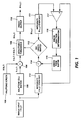
- Figure 1 is a a block diagram showing a system in which the present invention may find use;
- Figure 2 is one example of an error distribution matrix for error fraction determination and distribution;
- Figure 3 is a a block diagram showing an alternative system in which the present invention may find use;and
- Figure 4 is a flow chart of the present invention.
- Referring now to the drawings where the showings are for the purpose of describing an embodiment of the invention and not for limiting same, a basic system for carrying out the present invention is shown in Figure 1. In the present case, gray level image data from image input 10 may be characterized as image data, each pixel of which is defined at a single level or optical density in a set of 'c' optical density levels, the number of members in the set of levels being larger than desired. Each pixel will be processed in the manner described hereinbelow, to redefine each pixel in terms of a new, smaller set of 'd' levels. In this process, 'c' and 'd' are integer values representing pixel depth. Here, color data may be represented by a number of independent channels which are handled independently, or the color data might be represented as vector data in a predefined color space, e.g.: RGB, CIELab etc., being submitted to vector operations in the thresholding,error calculation and correction. One common case of this method includes the conversion of data from a relatively large set of gray level values to one of two legal or allowed bin values for printing in a binary printer. Another case of this is the conversion of data from a relatively large set of color data expressed as red, green and blue, or cyan, magenta, yellow and black, to one of five legal bin values for printing, as described in EP-A-000,000 (Appln. No. 92 308 074.1), corresponding to United States Patent Appl. Ser. No. 07/755,380, entitled "Method for Quantization of Gray Level Pixel Data with Application of Under Compensated Error Diffusion", by Eschbach et al.
- An input image of the type to be processed as hereinafter described may be represented by a set of gray values (gray level pixels) arranged in an array of L lines, each line containing N gray values with depth b, with any one pixel in said array denoted by I(n,ℓ). Gray values are typically expressed as integers, with one example falling in the range from 0 to 255, although greater or lesser number of levels, as well as non-integer representations, are possible. An output image is considered to consist of pixels, each pixel corresponding to an output element that is printed by a digital printer or display.
- With reference now to Figure 1, image I(n,ℓ) is received at
image buffer 100, holding the information of one halftone cell. Atadder 104, a halftone screen, S(n,ℓ), a set of values stored inhalftone memory 106, is added to each pixel value of I(n,ℓ), to impose a periodic function thereon. The halftone screen may be the same screen for the whole image, but multiple screens may be used, with selection of the screen depending upon the current image data. Atadjustable threshold 108, a threshold is applied to the image, now representable as the signal I(n,ℓ)+S(n,ℓ), where the threshold is adjustable from halftone cell to halftone cell, as will be further described, in accordance with the ARIES method of halftoning. - While halftoning has been described for simplicity as the addition of a set of selected screen values to pixel values within a defined area of the image, in conjunction with a uniform application of a threshold level(s) to the combined values, it will be understood that the process of halftoning may also be represented by a set of varying thresholds defined at locations corresponding to pixels over a given area of the image. A halftone cell, as used herein, is generally smaller than the total image and will be replicated in a predetermined scheme in order to cover an area of the image. A method for an efficient representation of variable angle halftone cells by a dither matrix and a corresponding replication scheme, is given in US-A 4,149,194 to Holladay. The output of a process using a dither matrix is a set of pixel values, having a number of members less than the input set of values. Commonly, the set of output values is binary, either black or white, or a spot or no spot, although the values might be gray as described in EP-A-000,000, corresponding to United States Patent Application Ser. No. 07/583,337 by Shiau. The binary output of a single halftone cell is a set of pixels that are either black or white which together form a "dot". Single pixels, black or white, surrounded respectively by white or black pixels, are difficult to print with electrophotographic devices. For this reason, standard dither matrices for electrophotographic applications tend to cluster pixels together, with growth pattern that begins in a central area of the halftone cell and grows as more elements of the cell are black. Such a dot pattern is printable on electrophotographic devices.
- The output of
adjustable threshold 108, the signal B(n,ℓ) which in a binary system is a set of binary, or black and white pixels, is stored tooutput buffer 110, from which it can be directed to an output device. Signal B(n,ℓ) is also integrated to provide an average gray output value over a halftone cell atblock 111, and the average gray output value is directed to comparator 112 (DO GRAYS MATCH) to be compared with the average gray input value of the input image over the halftone cell, generated atintegrator 113 and corrected by error from previous cells added to the average gray value at adder 114 (as will be described further below).Comparator 112 adjustsvariable threshold 108 to minimize the deviation between I(n,ℓ) and B(n,ℓ) over the halftone cell. -
Error determination block 117 calculates a difference between the average gray input value generated atintegrator 113 and average gray output value output generated atintegrator 111. This gray value error is passed to error fraction determination block 116 where the fractional error values are calculated and passed to theerror term buffer 115 to be used in the processing of subsequent halftone cells. Figure 2 shows one such fractional error distribution, in which for each unprocessed halftone cell identified in a neighborhood of the current halftone cell identified by *, a fractional error value, equal to the error ε, multiplied by a coefficient corresponding to the halftone cell position in the neighborhood with respect to the halftone cell from which ε is derived, and the factor 1/48, will be added to a subsequent halftone cell. It will, of course, be appreciated that any particular halftone cell is a member of the neighborhoods of several halftone cells and accordingly, a final error term that is added to the halftone cell is the sum of several fractional errors. Other fractional error weighting and distribution schemes such as those described by Floyd and Steinberg, Jarvis, Stucki, in EP-A-000,000 (Appln. No. 92 308 074.1), corresponding to United States Patent Appl. Ser. No. 07/755,380, entitled "Method for Quantization of Gray Level Pixel Data with Application of Under Compensated Error Diffusion", by Eschbach, and EP-A-000,000, corresponding to United States Patent Appl. Ser. No. 07/672,987, entitled "Method for Image Conversion with Application of Multiple Error Diffusion Matrices", by Eschbach, as well as many others, may be employed. While those schemes are described for pixel-to-pixel error distribution, the principal or error distribution on a dot-to-dot basis is similar. - As thus far described, the error diffusing functionality of the arrangement of Figure 1 is generally similar to the MAE method of error diffusion of Schroeder. Clearly, the error diffusion method of Floyd and Steinberg could also be used, although the effect of limiting the distance by which error from a single pixel is propagated might be decreased. This method is shown in Figure 3, where like numbers indicate like elements, and where the error is now calculated between the average modified input gray level taken after
adder 114 and the average output gray level taken fromblock 111. As noted the significant difference between the two methods is that the error diffusion method of Floyd and Steinberg determines error as a function of the original image modified by error from previous pixels, and the output image, while the MAE method determines error as a function of the original image and the output image. It can no doubt be appreciated that the appropriate error term generated for each halftone cell can be used to update the value of each pixel before theintegration block 113. - The reference to adding error to a halftone cell may be understood in either of two ways. Error may be distributed among pixels forming the halftone cell, which may alter the number of pixels ON or OFF determined for the cell, or alternatively, once a halftone cell is determined or the number of pixels ON or OFF determined for the cell, the number of pixels ON or OFF may be increased or decreased to represent the added error. The methods are equivalent for the purposes of this description.
- As was previously noted, an adjustable threshold value is provided at
adjustable threshold 108. Adjustment of T may be in accordance with the above-mentioned ARIES method of halftone reproduction, described by P. Roetling in the above-mentioned article, and in US-A 4,051,536 to Roetling and US-A 4,633,327 to Roetling. - With reference now to Figure 4, there is shown a flow chart demonstrating the steps of the inventive process of quantizing pixel values in an image formed by a plurality of pixels, each pixel representing an optical density of the image at a location within the image, and having an original optical density value associated therewith selected from one of a set of c original optical density values that has a number of members larger than a desired output set of d optical density values, including steps 500) receiving an input pixel having a pixel value I(n,ℓ) in the image I(x,y); 510)_integrating or averaging I(x,y) over a halftone cell or dot to produce an average gray input value IDOTIN for the dot; 520) adding a corresponding gray error term EDOT for the halftone cell to the average gray input value IDOTIN; and 530), storing the modified average gray input value IDOTIN + EDOT. At step 540, for the halftone dot, an integer and fractional part of the modified gray input value are calculated, where the integer part refers to the total gray value, including error, over one halftone cell, expressed in pixel units to be printed black (#black pixels), while the fractional part EDOTIN refers to the difference between the integer part and the modified gray input value IDOTIN + EDOT. At step 550, the fractional part EDOTIN of the value is used as a gray error measure, to calculate gray error fractions for subsequent halftone cells; at step 560 gray error fractions are calculated based on a weighted error distribution such as that described in Figure 2, and at step 570, the error term buffer is updated to be used in subsequent halftone cells as error values EDOT to be added at step 520, where EDOT is the sum of error fractions of one or more halftone dots
- At
step 580, halftone screen values are added to the input pixels received atstep 500, in accordance with the position of the pixel in the cell; and atstep 590, the resultant values are arranged or sorted in a way that allows to identify pixels that will be set to black. Then, atstep 600, a number of pixels from the arrangement of values are set to "black", based on the information about the integer part of the modified gray value, fromblock 540. Atoutput step 610, the pixels are directed to an output, with the original spatial arrangement of the pixels received atstep 500 maintained, while the pixel values have been quantized. - Adjustment of T may be in accordance with the ARIES method of halftone reproduction, described by P. Roetling in the above-mentioned article and in US-A 4,051,536 and US-A 4,633,327.
- It should be noted that the use of the term "thresholding" throughout this description is meant to encompass other ways of making a distance decision between the input optical density value and the output optical density value. It will also be appreciated that while the description has referred to binary level quantization, the systems which provide multi-level output pixels other than two may use the invention as described with appropriate modifications to account for the number of pixel levels that can be produced in the output. Additionally, the system can be used to convert color data from a large set of possible color values to a smaller set of color values.
- The invention has been described with reference to a particular embodiment. Modifications and alterations will occur to others upon reading and understanding this specification. It is intended that all such modifications and alterations are included insofar as they come within the scope of the appended claims or equivalents thereof.
Claims (9)
- A method of quantizing pixel values in an image formed by a plurality of pixels, each pixel representing an optical density of the image at a location within the image, and having an original optical density value associated therewith selected from one of a set of 'c' original optical density values that has a number of members larger than a desired output set of 'd' optical density values, including the steps:
for each group of pixels to be quantized, determining an average gray level input value for the image over an area of a halftone cell including the pixels;
determining a screen sum that is the addition of a stored screen value for the pixels determined by a position of the pixel within the area of the halftone cell, and the pixel value to produce screened pixel values;
thresholding the screened pixel value with a value T to obtain one or more output optical density values that are a member of the output set of 'd' optical density values, and directing said values to an output;
determining from the thresholded pixel values an average gray output value for the image over the area of the halftone cell;
determining an error value, that is a difference between the average gray output value and a first gray input value;
storing a weighted error value, that is a function of the error value, for each of a set of halftone cells or pixels in an error distribution neighborhood;
updating an error buffer holding error terms to be added to unprocessed halftone cells in the image with the weighted error value;
determining a second input gray level value and comparing the second input gray value and the average gray output value; and
responsive to said comparison, adjusting value T so that the average gray level between of the input image and the output image are about equal. - The method of claim 1, wherein:(1) said first gray input value is the average gray input value, said weighted error value is a weighted portion of the error value, and said second input gray value is the sum of an error term and an average input gray value; or(2) said first input gray value is the average input gray value modified by an error term determined in quantizing pixels in at least one previous halftone cell, and said second gray input value is said modified value.
- A method of quantizing pixel values in an image formed by a plurality of pixels, each pixel representing an optical density of the image at a location within the image, and having an original optical density value associated therewith selected from one of a set of 'c' original optical density values that has a number of members larger than a desired output set of 'd' optical density values, including the steps:
thresholding an optical density value of each pixel having an original optical density value against at least one threshold value T, to obtain an optical density value that is a member of the output set of 'd' optical density values;
for a set of pixels in the image forming a halftone cell determining a difference between a first input gray value of the image and an average gray output value of the thresholded image, and distributing a weighted portion of said difference to at least one unprocessed halftone cell;
comparing a second input gray value with the average output gray level value for the cell, and dynamically varying said at least one threshold value T in accordance with the comparison, so that said input gray level value and said output gray level values are about equal. - The method of claim 3, wherein:(1) said first input gray value comprises an average input gray value of the image, and said second input gray value is the sum of the average gray input level and a weighted portion of the difference determined for a previously processed halftone cell; or(2) said difference comprises an error value, said first input gray value comprises an average input gray value modified by the addition of a weighted error portion from at least one previously processed halftone cell, said second input gray value is said modified average gray input value.
- An arrangement for quantizing pixel values in an image formed by a plurality of pixels, each pixel having a value representing an optical density of the image at a location within the image, and having an original optical density value associated therewith selected from one of a set of 'c' original optical density values that has a number of members larger than a desired output set of 'd' optical density values, comprising:
a source of pixels having one of 'c' original optical density values;
an adder for summing a stored screen value and a pixel value of a pixel to be quantized, said screen value received from a screen memory and determined by a position of the pixel to be quantized within the area of a halftone cell, to produce a screened pixel value;
an adjustable thresholding means for thresholding the screened pixel value with a value T to obtain an output optical density value that is a member of the output set of 'd' optical density values;
an image data output, directing pixels having an output optical density value that is one of 'd' optical density values out of the arrangement;
an input integrator, determining an average gray input value for the image over an area of the halftone cell including the pixel to be processed;
an output integrator, determining from the output of the adjustable thresholding means, an average gray level value for output image data, over an area of the halftone cell including the pixel;
a gray error comparator, for comparing the average gray output value of the image and the average gray input value, and producing a gray error that is the difference therebetween;
a gray error memory, storing gray error terms, each gray error term a weighted portion of the determined gray error, to be applied to each halftone cell in a predetermined neighborhood thereof; and
an adder for summing a gray error term stored in the gray error term memory and the average gray input value, to produce a modified average gray input value; and
means for adjusting T so that the average gray input value and the average gray output value are about equal. - The arrangement of claim 5, wherein the gray error comparator is adapted to compare the average gray output value of the image and the modified average gray input value, and produce a gray error term that is the difference therebetween.
- An arrangement for quantizing pixel values in an image formed by a plurality of pixels, each pixel representing an optical density of the image at a location within the image, and having an original optical density value associated therewith selected from one of a set of 'c' original optical density values that has a number of members larger than a desired output set of 'd' optical density values, comprising:
means for thresholding an optical density value of each pixel having an original optical density value against at least one threshold value T, to obtain an optical density value that is a member of the output set of 'd' optical density values;
means for determining, for a set of pixels in the image forming a halftone cell, a difference between a first input gray value of the image and an average gray output value of the thresholded image, and distributing a weighted portion of said difference to at least one unprocessed halftone cell;
means for comparing a second input gray value with the average output gray level value for the cell, and dynamically varying said at least one threshold value T in accordance with the comparison, so that said input gray level value and said output gray level values are about equal. - The arrangement of claim 7, wherein:(1) said first input gray value comprises an average input gray value of the image, and said second input gray value is the sum of the average gray input level and the determined difference; or(2) said first input gray value comprises an average input gray value of the image modified by the addition of an error term from at least one previously processed halftone cell, and said second input gray value is the sum of the average input gray value and the determined difference.
- A method of quantizing pixel values in an image formed by a plurality of pixels, each pixel representing an optical density of the image at a location within the image, and having an original optical density value associated therewith selected from one of a set of 'c' original optical density values that has a number of members larger than a desired output set of 'd' optical density values, including steps:
receiving input pixel values for the image;
averaging pixels values in an area corresponding to a halftone cell in the image, to produce an average gray input value for the halftone cell;
adding a gray error term from at least one previously processed halftone cell, to the average gray input value, and storing the modified average gray input value;
calculating an integer part and fractional part of the modified gray input value, where the integer part is the modified average gray input value in integer pixel units, while the fractional part is the difference between the integer part and the modified gray input value;
storing to an error term buffer a set of gray error terms, each gray error term a weighted portion of the fractional part of the modified gray input value, to be applied to each halftone cell in a predetermined neighborhood thereof;
determining a screen sum that is the addition of a stored screen value for the pixel value determined by a position of the pixel within the area of the halftone cell;
for the cell, arranging the screen sums in order of value;
beginning with the first screen sum, setting a number of pixels represented by the screen sums in the halftone cell to a selected state, the number of pixels set to the selected state equal to the integer calculated integer part.
Applications Claiming Priority (2)
| Application Number | Priority Date | Filing Date | Title |
|---|---|---|---|
| US07/802,809 US5243443A (en) | 1991-12-06 | 1991-12-06 | Halftoning with error feedback and image dependent enhancement |
| US802809 | 1997-02-18 |
Publications (3)
| Publication Number | Publication Date |
|---|---|
| EP0545734A2 true EP0545734A2 (en) | 1993-06-09 |
| EP0545734A3 EP0545734A3 (en) | 1994-02-16 |
| EP0545734B1 EP0545734B1 (en) | 1999-04-14 |
Family
ID=25184765
Family Applications (1)
| Application Number | Title | Priority Date | Filing Date |
|---|---|---|---|
| EP92311106A Expired - Lifetime EP0545734B1 (en) | 1991-12-06 | 1992-12-04 | Halftoning with error feedback and image dependent enhancement |
Country Status (4)
| Country | Link |
|---|---|
| US (1) | US5243443A (en) |
| EP (1) | EP0545734B1 (en) |
| JP (1) | JPH05252386A (en) |
| DE (1) | DE69228917T2 (en) |
Cited By (1)
| Publication number | Priority date | Publication date | Assignee | Title |
|---|---|---|---|---|
| CN101562683B (en) * | 2008-04-18 | 2011-09-07 | 佳能株式会社 | Image processing apparatus and method thereof |
Families Citing this family (57)
| Publication number | Priority date | Publication date | Assignee | Title |
|---|---|---|---|---|
| US5657137A (en) * | 1992-05-04 | 1997-08-12 | Hewlett-Packard Company | Color digital halftoning using black and secondary color replacement |
| US5585818A (en) * | 1992-05-19 | 1996-12-17 | Canon Kabushiki Kaisha | Display control unit and display control method |
| US5509085A (en) * | 1992-10-07 | 1996-04-16 | Seiko Epson Corporation | Image processor and printing apparatus which perform binary coding of color components |
| US5515180A (en) * | 1992-11-24 | 1996-05-07 | Sharp Kabushiki Kaisha | Image processing device |
| US5917614A (en) * | 1992-11-30 | 1999-06-29 | Levien; Raphael L | Method and apparatus for error diffusion screening of images with improved smoothness in highlight and shadow regions |
| US5313287A (en) * | 1993-04-30 | 1994-05-17 | Hewlett-Packard Company | Imposed weight matrix error diffusion halftoning of image data |
| JP3171993B2 (en) * | 1993-05-24 | 2001-06-04 | キヤノン株式会社 | Image processing method and apparatus |
| US5611022A (en) * | 1993-07-07 | 1997-03-11 | Dataproducts Corporation | Color imaging |
| US5521989A (en) * | 1993-08-05 | 1996-05-28 | Xerox Corporation | Balanced error diffusion system |
| US5377041A (en) * | 1993-10-27 | 1994-12-27 | Eastman Kodak Company | Method and apparatus employing mean preserving spatial modulation for transforming a digital color image signal |
| US5353127A (en) * | 1993-12-15 | 1994-10-04 | Xerox Corporation | Method for quantization gray level pixel data with extended distribution set |
| GB9405723D0 (en) * | 1994-03-23 | 1994-05-11 | Crosfield Electronics Ltd | Method and apparatus for producing a digital half-tone representation of an image |
| JPH08204971A (en) * | 1994-10-31 | 1996-08-09 | Xerox Corp | Image compression method using predictive coding and error diffusion |
| US5493416A (en) * | 1994-10-31 | 1996-02-20 | Xerox Corporation | Method combining error diffusion and traditional halftoning with arbitrary screen orientation |
| US5602653A (en) * | 1994-11-08 | 1997-02-11 | Xerox Corporation | Pixel pair grid halftoning for a hyperacuity printer |
| US5742405A (en) * | 1995-01-26 | 1998-04-21 | Eastman Kodak Company | Method and system for forming multi-level halftone images from an input digital image |
| JP3354741B2 (en) * | 1995-04-17 | 2002-12-09 | 富士通株式会社 | Halftone display method and halftone display device |
| US5587811A (en) * | 1995-04-28 | 1996-12-24 | Dataproducts Corporation | Halftone screen using spot function to rank pixels following one or more design rules |
| US5764810A (en) * | 1995-12-20 | 1998-06-09 | R.R. Donnelley & Sons Company, Inc. | Screenless conversion of continuous tone images with alterable dot spacing patterns |
| US5737453A (en) * | 1996-05-17 | 1998-04-07 | Canon Information Systems, Inc. | Enhanced error-diffusion method for color or black-and-white reproduction |
| US5835117A (en) * | 1996-05-31 | 1998-11-10 | Eastman Kodak Company | Nonlinear dithering to reduce neutral toe color shifts |
| US5835238A (en) * | 1996-06-27 | 1998-11-10 | Xerox Corporation | Phantom level edge enhanced error diffusion |
| US5701366A (en) * | 1996-09-04 | 1997-12-23 | Canon Information Systems, Inc. | Halftoning with gradient-based selection of dither matrices |
| US5805724A (en) * | 1996-09-24 | 1998-09-08 | Xerox Corporation | Method and system for hybrid error diffusion processing of image information using dynamic screens based on brightness/darkness settings |
| US5835687A (en) * | 1996-10-21 | 1998-11-10 | Vidar Systems Corporation | Methods and apparatus for providing digital halftone images with random error diffusion dithering |
| US6078687A (en) * | 1996-12-20 | 2000-06-20 | Texas Instruments Incorporated | Quantization for a digital printer using modulated image data |
| US5991513A (en) * | 1997-09-30 | 1999-11-23 | Levien; Raphael L | Method and apparatus for suppressing moire patterns |
| JP3119227B2 (en) | 1998-01-19 | 2000-12-18 | 日本電気株式会社 | Print data processing device |
| US6185005B1 (en) | 1998-04-30 | 2001-02-06 | Hitachi Koki Imaging Solutions, Inc. | Half tone image enhancement for printers |
| US6717700B1 (en) | 1999-07-01 | 2004-04-06 | Xerox Corporation | Method and system for adjusting binary images |
| JP3961736B2 (en) * | 2000-02-04 | 2007-08-22 | 株式会社リコー | Image processing device |
| US6678073B1 (en) | 2000-02-08 | 2004-01-13 | Oak Technology, Inc. | Error diffusion method and apparatus |
| US7158262B2 (en) * | 2000-02-17 | 2007-01-02 | Hewlett-Packard Development Company, L.P. | Multi-level error diffusion apparatus and method of using same |
| US6763144B1 (en) * | 2000-06-01 | 2004-07-13 | Creo Il, Ltd. | Halftone image reproduction |
| US20020016750A1 (en) * | 2000-06-20 | 2002-02-07 | Olivier Attia | System and method for scan-based input, storage and retrieval of information over an interactive communication network |
| DE50103922D1 (en) * | 2000-12-08 | 2004-11-04 | Oce Printing Systems Gmbh | METHOD FOR HALF-TONE REPRESENTATION OF AN IMAGE, AND IMAGE PROCESSING DEVICE AND PRINTING DEVICE FOR CARRYING OUT THIS METHOD |
| US7131980B1 (en) | 2001-01-18 | 2006-11-07 | Dvl Acquisitions Sub, Inc. | Surgical suturing instrument and method of use |
| US7011668B2 (en) | 2001-07-23 | 2006-03-14 | Dvl Acquistion Sub, Inc. | Surgical suturing instrument and method of use |
| WO2003096885A2 (en) | 2002-05-17 | 2003-11-27 | Onux Medical, Inc. | Surgical suturing instrument and method of use |
| US7551323B2 (en) * | 2003-04-16 | 2009-06-23 | Lexmark International, Inc. | Systems and methods for error diffusion |
| US20040218220A1 (en) * | 2003-04-29 | 2004-11-04 | International Business Machines Corporation | Enhanced error diffusion |
| US7156311B2 (en) * | 2003-07-16 | 2007-01-02 | Scanbuy, Inc. | System and method for decoding and analyzing barcodes using a mobile device |
| US7242816B2 (en) * | 2003-08-11 | 2007-07-10 | Scanbuy, Inc. | Group average filter algorithm for digital image processing |
| US7387250B2 (en) * | 2003-12-04 | 2008-06-17 | Scanbuy, Inc. | System and method for on the spot purchasing by scanning barcodes from screens with a mobile device |
| US7168621B2 (en) * | 2003-12-04 | 2007-01-30 | Scanbury, Inc. | Section based algorithm for image enhancement |
| US7296747B2 (en) * | 2004-04-20 | 2007-11-20 | Michael Rohs | Visual code system for camera-equipped mobile devices and applications thereof |
| KR100611981B1 (en) * | 2004-05-01 | 2006-08-11 | 삼성전자주식회사 | Method and apparatus for halftoning digital images |
| US7309015B2 (en) * | 2004-07-14 | 2007-12-18 | Scanbuy, Inc. | Mobile device gateway providing access to instant information |
| US7733532B2 (en) * | 2004-10-27 | 2010-06-08 | Marvell International Technology Ltd. | Laser print apparatus with dual halftones |
| US7639887B2 (en) | 2004-12-14 | 2009-12-29 | Intel Corporation | Error diffusion-based image processing |
| US20060171602A1 (en) * | 2005-01-31 | 2006-08-03 | International Business Machines Corporation | Method and system for using a look-up table for a linear operation in image processing |
| US7518754B2 (en) * | 2005-08-18 | 2009-04-14 | Lexmark International, Inc. | Apparatus and method for error diffusion with dither |
| US8016187B2 (en) * | 2006-02-21 | 2011-09-13 | Scanbury, Inc. | Mobile payment system using barcode capture |
| US8150163B2 (en) | 2006-04-12 | 2012-04-03 | Scanbuy, Inc. | System and method for recovering image detail from multiple image frames in real-time |
| DE102006021387B4 (en) * | 2006-05-08 | 2008-04-03 | OCé PRINTING SYSTEMS GMBH | Printing system and method for operating a printing system |
| US8625161B2 (en) * | 2009-11-19 | 2014-01-07 | International Business Machines Corporation | Multibit digital halftoning, indexing 2D and 3D lookup tables |
| JP2018533322A (en) | 2016-01-29 | 2018-11-08 | ヒューレット−パッカード デベロップメント カンパニー エル.ピー.Hewlett‐Packard Development Company, L.P. | Error diffusion |
Citations (3)
| Publication number | Priority date | Publication date | Assignee | Title |
|---|---|---|---|---|
| US4196454A (en) * | 1978-12-04 | 1980-04-01 | Xerox Corporation | Tone error control for relatively large image areas |
| GB2149611A (en) * | 1983-11-10 | 1985-06-12 | Xerox Corp | Enhancement halftoning |
| JPH0380767A (en) * | 1989-08-24 | 1991-04-05 | Ricoh Co Ltd | Gradation recorder for image |
Family Cites Families (8)
| Publication number | Priority date | Publication date | Assignee | Title |
|---|---|---|---|---|
| US4051536A (en) * | 1975-03-14 | 1977-09-27 | Xerox Corporation | Electronic halftone imaging system |
| US4149194A (en) * | 1977-07-07 | 1979-04-10 | Xerox Corporation | Variable angle electronic halftone screening |
| DE3067060D1 (en) * | 1979-12-20 | 1984-04-19 | Cambridge Consultants | Apparatus and method for generating a dispersed dot half tone picture from a continuous tone picture |
| US4654721A (en) * | 1985-04-12 | 1987-03-31 | International Business Machines Corporation | System for reproducing multi-level digital images on a bi-level printer of fixed dot size |
| US4955065A (en) * | 1987-03-17 | 1990-09-04 | Digital Equipment Corporation | System for producing dithered images from continuous-tone image data |
| US4924322A (en) * | 1988-03-18 | 1990-05-08 | Matsushita Electric Industrial Co., Ltd. | Bi-level image display signal processing apparatus |
| US5045952A (en) * | 1989-08-21 | 1991-09-03 | Xerox Corporation | Method for edge enhanced error diffusion |
| JPH03131173A (en) * | 1989-10-17 | 1991-06-04 | Canon Inc | Picture processing system |
-
1991
- 1991-12-06 US US07/802,809 patent/US5243443A/en not_active Expired - Lifetime
-
1992
- 1992-11-27 JP JP4318978A patent/JPH05252386A/en not_active Withdrawn
- 1992-12-04 DE DE69228917T patent/DE69228917T2/en not_active Expired - Fee Related
- 1992-12-04 EP EP92311106A patent/EP0545734B1/en not_active Expired - Lifetime
Patent Citations (3)
| Publication number | Priority date | Publication date | Assignee | Title |
|---|---|---|---|---|
| US4196454A (en) * | 1978-12-04 | 1980-04-01 | Xerox Corporation | Tone error control for relatively large image areas |
| GB2149611A (en) * | 1983-11-10 | 1985-06-12 | Xerox Corp | Enhancement halftoning |
| JPH0380767A (en) * | 1989-08-24 | 1991-04-05 | Ricoh Co Ltd | Gradation recorder for image |
Non-Patent Citations (1)
| Title |
|---|
| PATENT ABSTRACTS OF JAPAN vol. 15, no. 254 (E-1083)27 June 1991 & JP-A-03 080 767 (RICOH CO LTD) 5 April 1991 & US-A-5 077 615 (K. TSUJI) 31 December 1991 * |
Cited By (3)
| Publication number | Priority date | Publication date | Assignee | Title |
|---|---|---|---|---|
| CN101562683B (en) * | 2008-04-18 | 2011-09-07 | 佳能株式会社 | Image processing apparatus and method thereof |
| EP2111032A3 (en) * | 2008-04-18 | 2012-12-19 | Canon Kabushiki Kaisha | Image processing apparatus and method thereof |
| US8351083B2 (en) | 2008-04-18 | 2013-01-08 | Canon Kabushiki Kaisha | Image processing apparatus and method thereof for decreasing the tonal number of an image |
Also Published As
| Publication number | Publication date |
|---|---|
| DE69228917D1 (en) | 1999-05-20 |
| EP0545734A3 (en) | 1994-02-16 |
| US5243443A (en) | 1993-09-07 |
| JPH05252386A (en) | 1993-09-28 |
| DE69228917T2 (en) | 1999-10-07 |
| EP0545734B1 (en) | 1999-04-14 |
Similar Documents
| Publication | Publication Date | Title |
|---|---|---|
| US5243443A (en) | Halftoning with error feedback and image dependent enhancement | |
| US5268774A (en) | Halftoning with enhanced dynamic range and edge enhanced error diffusion | |
| EP0602854B1 (en) | Clustered halftoning with dot-to-dot error diffusion | |
| US5325211A (en) | Error diffusion with output and input based feedback | |
| CA2076780C (en) | Method for quantization gray level pixel data with application of under compensated error diffusion | |
| US5353127A (en) | Method for quantization gray level pixel data with extended distribution set | |
| US5535019A (en) | Error diffusion halftoning with homogeneous response in high/low intensity image regions | |
| US5226096A (en) | Digital halftoning with selectively applied dot-to-dot error diffusion | |
| EP0622950B1 (en) | Imposed weight matrix error diffusion halftoning of image data | |
| US7440139B2 (en) | Systems and methods for controlling a tone reproduction curve using error diffusion | |
| US5521989A (en) | Balanced error diffusion system | |
| US5130823A (en) | Error diffusion system | |
| US5374997A (en) | High addressability error diffusion with minimum mark size | |
| EP0817465B1 (en) | Error diffusion method with symmetric enhancement | |
| US5784496A (en) | Error sum method and apparatus for intercolor separation control in a printing system | |
| US5289294A (en) | Image processing apparatus | |
| EP0817466B1 (en) | Edge enhanced error diffusion | |
| US6778299B2 (en) | Error diffusion with partial dots method and system | |
| US7095530B2 (en) | Color vector halftoning using a successive filling with improved color registration latitude | |
| JP4248654B2 (en) | Processing device for preparing document image to be output to output device | |
| US6006011A (en) | Target patterns controlled error management | |
| US20030112468A1 (en) | Reduced-buffer error diffusion |
Legal Events
| Date | Code | Title | Description |
|---|---|---|---|
| PUAI | Public reference made under article 153(3) epc to a published international application that has entered the european phase |
Free format text: ORIGINAL CODE: 0009012 |
|
| AK | Designated contracting states |
Kind code of ref document: A2 Designated state(s): DE FR GB |
|
| PUAL | Search report despatched |
Free format text: ORIGINAL CODE: 0009013 |
|
| AK | Designated contracting states |
Kind code of ref document: A3 Designated state(s): DE FR GB |
|
| 17P | Request for examination filed |
Effective date: 19940802 |
|
| 17Q | First examination report despatched |
Effective date: 19960729 |
|
| GRAG | Despatch of communication of intention to grant |
Free format text: ORIGINAL CODE: EPIDOS AGRA |
|
| GRAG | Despatch of communication of intention to grant |
Free format text: ORIGINAL CODE: EPIDOS AGRA |
|
| GRAH | Despatch of communication of intention to grant a patent |
Free format text: ORIGINAL CODE: EPIDOS IGRA |
|
| GRAH | Despatch of communication of intention to grant a patent |
Free format text: ORIGINAL CODE: EPIDOS IGRA |
|
| GRAA | (expected) grant |
Free format text: ORIGINAL CODE: 0009210 |
|
| AK | Designated contracting states |
Kind code of ref document: B1 Designated state(s): DE FR GB |
|
| REF | Corresponds to: |
Ref document number: 69228917 Country of ref document: DE Date of ref document: 19990520 |
|
| ET | Fr: translation filed | ||
| PLBE | No opposition filed within time limit |
Free format text: ORIGINAL CODE: 0009261 |
|
| STAA | Information on the status of an ep patent application or granted ep patent |
Free format text: STATUS: NO OPPOSITION FILED WITHIN TIME LIMIT |
|
| 26N | No opposition filed | ||
| PGFP | Annual fee paid to national office [announced via postgrant information from national office to epo] |
Ref country code: GB Payment date: 20001129 Year of fee payment: 9 Ref country code: DE Payment date: 20001129 Year of fee payment: 9 |
|
| PGFP | Annual fee paid to national office [announced via postgrant information from national office to epo] |
Ref country code: FR Payment date: 20001212 Year of fee payment: 9 |
|
| PG25 | Lapsed in a contracting state [announced via postgrant information from national office to epo] |
Ref country code: GB Free format text: LAPSE BECAUSE OF NON-PAYMENT OF DUE FEES Effective date: 20011204 |
|
| REG | Reference to a national code |
Ref country code: GB Ref legal event code: IF02 |
|
| PG25 | Lapsed in a contracting state [announced via postgrant information from national office to epo] |
Ref country code: DE Free format text: LAPSE BECAUSE OF NON-PAYMENT OF DUE FEES Effective date: 20020702 |
|
| GBPC | Gb: european patent ceased through non-payment of renewal fee |
Effective date: 20011204 |
|
| PG25 | Lapsed in a contracting state [announced via postgrant information from national office to epo] |
Ref country code: FR Free format text: LAPSE BECAUSE OF NON-PAYMENT OF DUE FEES Effective date: 20020830 |
|
| REG | Reference to a national code |
Ref country code: FR Ref legal event code: ST |