EP0545225B1 - Digital communication system using superposed transmission of high speed and low speed digital signals - Google Patents
Digital communication system using superposed transmission of high speed and low speed digital signals Download PDFInfo
- Publication number
- EP0545225B1 EP0545225B1 EP19920119979 EP92119979A EP0545225B1 EP 0545225 B1 EP0545225 B1 EP 0545225B1 EP 19920119979 EP19920119979 EP 19920119979 EP 92119979 A EP92119979 A EP 92119979A EP 0545225 B1 EP0545225 B1 EP 0545225B1
- Authority
- EP
- European Patent Office
- Prior art keywords
- signals
- high speed
- digital signals
- modulated
- speed digital
- Prior art date
- Legal status (The legal status is an assumption and is not a legal conclusion. Google has not performed a legal analysis and makes no representation as to the accuracy of the status listed.)
- Expired - Lifetime
Links
Images


Classifications
-
- H—ELECTRICITY
- H04—ELECTRIC COMMUNICATION TECHNIQUE
- H04B—TRANSMISSION
- H04B7/00—Radio transmission systems, i.e. using radiation field
- H04B7/14—Relay systems
- H04B7/15—Active relay systems
- H04B7/204—Multiple access
- H04B7/216—Code division or spread-spectrum multiple access [CDMA, SSMA]
Definitions
- the present invention relates to a superposed digital signal transmission scheme for transmitting high speed digital signals and low speed digital signals used in a digital communication system.
- the currently adopted satellite video communication system uses a video signal transmission earth station capable of transmitting both video signals and voice signals and small earth stations capable of transmitting only voice signals, in which the transmission of the video signals is realized as a one-way transmission in an analog FM mode from the video signal transmission earth station, while the transmission of the answer-back voice signals from the small earth station which receives the video signals from the video signal transmission earth station is realized by using a terrestrial network.
- the superposed transmission of a low speed digital signal and a wide band signal is known from documents DE-A-36 44 168 and DE-A-36 44 174.
- the low speed signal is spectrum-expanded using a pseudo-noise sequence.
- the spectrum-expanded signal is then modulated on a carrier and transmitted to a satellite using a low power earth station. It becomes superposed with a broad band signal e.g. a video signal, which is carried by the satellite.
- a broad band signal e.g. a video signal, which is carried by the satellite.
- the wide band signal carried by the satellite can itself be a QPSK modulated digital signal.
- a method of superposed transmission of high and low speed digital signals in a digital communication system comprising the steps of: (a1) forward error correction encoding high speed digital signals to be transmitted to obtain encoded high speed digital signals; (a2) modulating a first carrier in a first frequency with the encoded high speed digital signals obtained at the step (a1) to obtain modulated high speed signals; (b1) forward error correction encoding low speed digital signals to be transmitted to obtain encoded low speed digital signals; (b2) spreading a spectrum of the encoded low speed digital signals obtained at the step (b1) to obtain spread spectrum signals; (b3) modulating a second carrier in a second frequency with the spread spectrum signals obtained at the step (b2) to obtain modulated spread spectrum signals; (c) transmitting the modulated high speed signals obtained at the step (a2) and the modulated spread spectrum signals obtained at the step (b3) through an identical frequency band on a transmission path in a form of superposed transmission signals; (d1) demodulating the modulated high speed signals in the superposed
- a digital communication system using superposed transmission of high and low speed digital signals comprising: receiver means for receiving modulated high speed signals and modulated spread spectrum signals through an identical frequency band on a transmission path in a form of superposed transmission signals; first demodulator means for demodulating the modulated high speed signals in the superposed transmission signals transmitted through the transmission path and received by the receiver means to obtain encoded high speed digital signals; first decoder means for forward error correction decoding the encoded high speed digital signals obtained by the first demodulator means to obtain high speed digital signals; replica generation means for obtaining a phase inverted replica of the modulated high speed signals in the superposed transmission signals transmitted through the transmission path and received by the receiver means according to the high speed digital signals obtained by the first decoder means; power combiner means for power combining the superposed transmission signals transmitted through the transmission path and received by the receiver means with the phase inverted replica obtained by the replica generation means to obtain modulated spread spectrum signals in the superposed transmission signals; spectrum despreader means for despreading a spectrum
- an apparatus for superposed transmission of high and low speed digital signals comprising: first encoder means for forward error correction encoding high speed digital signals to be transmitted to obtain encoded high speed digital signals; first modulator means for modulating a first carrier in a first frequency with the encoded high speed digital signals obtained by the first encoder means to obtain modulated high speed signals to be transmitted through a transmission path; second encoder means for forward error correction encoding low speed digital signals to be transmitted to obtain encoded low speed digital signals; spectrum spreader means for spreading a spectrum of the encoded low speed digital signals obtained by the second encoder means to obtain spread spectrum signals; second modulator means for modulating a second carrier in a second frequency with the spread spectrum signals obtained by the spectrum spreader means to obtain modulated spread spectrum signals to be transmitted through the transmission path; and transmitter means for transmitting the modulated high speed signals obtained by the first modulator means and the modulated spread spectrum signals obtained by the second modulator means through an identical frequency band on the transmission path in a form of superposed transmission signals.
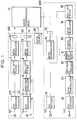
- FIG. 1 one embodiment of a digital communication system using superposed transmission of high speed and low speed digital signals according to the present invention will be described in detail.
- the entered high speed digital signals are then supplied to an FEC (Forward Error Correction) encoder 2 for applying a convolutional encoding with an encoding rate of (n-1)/n, where n is a natural number.
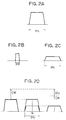
- the high speed digital signals have a power spectrum as shown in Fig. 2A, with a frequency band equivalent to 2fb.
- a waveform shaped output of the roll-off filter 3 is then supplied to a QPSK (Quadrature Phase Shift Keying) modulator 4 to make a quadrature modulation of a carrier in a frequency fc1 to obtain high speed QPSK signals.
- QPSK Quadrature Phase Shift Keying
- a low speed signal transmitting station 110 input high speed input low speed digital signals to be transmitted are entered from an input terminal 5 at a speed of fd2 (bit/sec), where fd2 ⁇ fd1.
- the entered low speed digital signals are then supplied to an FEC encoder 6 for applying a convolutional encoding with an encoding rate of (n'-1)/n', where n' is a natural number.
- the low speed digital signals have a power spectrum as shown in Fig. 2B, with a frequency band equivalent to 2fb'.
- the spectrum spreader 7 the spectrum of the I and Q signals supplied from the FEC encoder 6 are spread to obtain SSMA (Spread Spectrum Multiple Access) signals.
- SSMA Session Multiple Access
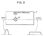
- the spectrum spreader 7 is of a direct sequence type in which an output is obtained by multiplying an input directly with spectrum spreading codes at a multiplier 27.
- the obtained SSMA signals are then supplied at a speed of fb to a roll-off filter 8 for applying a waveform shaping with a roll-off rate ⁇ .
- the SSMA signals have a power spectrum as shown in Fig. 2C, with a frequency band equivalent to 2fb.
- a waveform shaped output of the roll-off filter 8 is then supplied to a QPSK modulator 9 to make a quadrature modulation of a carrier in a frequency fc2 to obtain SSMA-QPSK signals.
- the high speed QPSK signals and the SSMA-QPSK signals obtained by the QPSK modulators 4 and 9 are then transmitted from a high speed signal transmitter device 51 provided at the high speed signal transmitter station 100 and a low speed signal transmitter device 52 provided at the low speed signal transmitter station 110, respectively, through a radio transmission path 14 by using an identical frequency band, such that the high speed and the low speed digital signals are superposed on the radio transmission path 14.
- the superposed high speed and low speed digital signals have power spectra as shown in Fig. 2D, with a frequency band equivalent to 2fb and a common central frequency fc.
- the superposed high speed and low speed digital signals at the radio transmission path 14 have the continuous wave (CW) power ratio of the high speed signals to the SSMA signals indicated as D/U (Desired to Undesired signal power ratio) in Fig. 2D.
- CW continuous wave
- the superposed high speed QPSK and SSMA-QPSK signals received from the radio transmission path 14 by a receiver station receiver device 53 are entered into a QPSK demodulator 15 for demodulating the received superposed signals.
- the demodulated output signals of the QPSK demodulator 15 are supplied to an FEC decoder 16 for making the error correction on the demodulated output signals, which is a Viterbi decoder capable of decoding the high speed digital signals encoded by the FEC encoder 2, such that output high speed digital signals reproducing the input high speed digital signals are obtained at an output terminal 17, at a speed of fd1 which is the same as the speed of the input high speed digital signals.
- the demodulated output signals of the QPSK demodulator 15 are also supplied to a roll-off filter 18 for applying a waveform shaping with a roll-off rate ⁇ , and a waveform shaped output of the roll-off filter 18 is then supplied to a QPSK modulator 19 to make a quadrature modulation of a carrier in a frequency fc2, so as to obtain a replica of the high speed QPSK signals in the same amplitude as the high speed QPSK signals.
- the obtained replica of the high speed QPSK signals is supplied to a phase shifter 20 for inverting a phase of this replica, and the phase inverted replica is supplied to a power combiner 21.
- the power combiner 21 is also supplied with the superposed high speed QPSK and SSMA-QPSK signals received from the radio transmission path 14, such that the power combiner 21 combines the received superposed signals with the phase inverted replica, so as to cancel the high speed digital signals in the received superposed signals and extract the SSMA-QPSK signals in the received superposed signals.
- the SSMA-QPSK signals obtained by the power combiner 21 are then supplied to a spectrum despreader 22 for despreading the spectrum of the SSMA-QPSK signals.
- This spectrum despreader 22 carries out an inverse operation of the spectrum spreading operation made by the spectrum spreader 7.
- the spectrum despread output signals obtained by the spectrum despreader 22 are supplied to a QPSK demodulator 23 for demodulating the spectrum despread output signals.
- the demodulated output signals of the QPSK demodulator 23 are supplied to an FEC decoder 24 for making the error correction on the demodulated output signals, which is a Viterbi decoder capable of decoding the low speed digital signals encoded by the FEC encoder 6, such that output low speed digital signals reproducing the input low speed digital signals are obtained at an output terminal 25, at a speed of fd2 which is the same as the speed of the input low speed digital signals.
- Fig. 1 also shows a noise source 26 for power combining a variable amount of noise to the radio transmission path 14, which was used in the experiment to be described below for the purpose of realizing the realistic transmission condition.
- the low speed digital signals are transmitted by using the FEC and the SSMA mode through the identical frequency band as the high speed digital signals. Consequently, the transmission of the superposed high speed and low speed digital signals can be realized by using a single transponder, and the transmission of the SSMA signals can be made by using a low power SSPA (Solid State Power Amplifier) having a transmission power of less than 1 watt.
- SSPA Solid State Power Amplifier
- the high speed digital signals which can potentially interfere with the SSMA signals are cancelled out in obtaining the output low speed digital signals by using the replica of the high speed digital signals.
- the FEC encoders 2 and 6 may use any FEC encoding other than the convolutional encoding used in this embodiment, such as those using the Reed-Solomon codes, BCH codes, etc., and the FEC decoders 16 and 24 mat use any FEC decoding other than the Viterbi decoding used in this embodiment.
- roll-off filters 3, 8, and 18 used in this embodiment may be replaced by other types of waveform shaping circuit.
- QPSK modulation used in this embodiment may be replaced by BPSK (Binary Phase Shift Keying) modulation.
- the spectrum spreader 7 and the spectrum despreader 22 may use the spectrum spreading other than the direct sequence type used in this embodiment, such as a frequency hopping type.
- reception of the superposed high speed and low speed digital signals from the radio transmission path 14 can be made by using any desired detection mode including a coherent detection and a differential detection.
- radio transmission path 14 may be replaced by other types of transmission path such as an optical fiber transmission path, if desired.
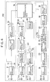
- a digital communication system of Fig. 1 as described above may be modified as shown in Fig. 4.
- This alternative configuration shown in Fig. 4 differs from the configuration of Fig.
- the high speed signal transmitting part and the low speed signal receiving part are commonly included in a transmitting station 150, in which the input of the roll-off filter 18 is provided by the output of the FEC encoder 2, instead of the output of the QPSK demodulator 15, and the SSMA-QPSK signals transmitted from the low speed signal transmitting station 110 through the transmission path 14 are received by a transmitting station receiver device 54 provided at the transmitting station 150 while the high speed QPSK signals transmitted from the transmitting station 150 are received by a receiver device 55 provided at a receiving station 210.
- the experiment was conducted by using the noise source 26 shown in Fig. 1 for power combining a variable amount of noise to the radio transmission path 14, for the purpose of realizing the realistic transmission condition.
- Fig. 5 shows the bit error rate Pe for the low speed digital signals transmitted between the input terminal 5 and the output terminal 25, as a function of the signal to noise power ratio Eb/No, which was measured by varying the amount of noise combined from the noise source 26.
- a curve A indicates the result of this experiment using the digital communication system of the embodiment described above for a case of transmitting two channels of the low speed digital signals with the D/U ratio of the high speed digital signals with respect to the low speed digital signals equal to 25 dB.
- Fig. 5 also shows a curve B which indicates a comparative result for a case of transmitting two channels of the low speed digital signals with the D/U ratio of the high speed digital signals with respect to the low speed digital signals equal to 25 dB, by using only the FEC without the cancellation of the high speed digital signals using the replica.
- Fig. 5 also shows a curve T1 which indicates a theoretical value for a case of transmitting only one channel of the low speed digital signals by using only the FEC without spectrum spreading.
- a curve C indicates the result of this experiment using the digital communication system of the embodiment described above for a case of transmitting two channels of the low speed digital signals.
- Fig. 6 also shows a curve D which indicates a comparative result for a case of transmitting two channels of the low speed digital signals by using only the FEC without the cancellation of the high speed digital signals using the replica.
- Fig. 7 shows the number of channels available for the low speed digital signals, for a constant total transmission power for the low speed digital signals equal to that required in a case of transmitting two channels of the low speed digital signals with the D/U ratio equal to 20 dB, as a function of the D/U ratio.
- the necessary transmission power for the low speed digital signals per channel becomes smaller, so that the number of channels available for the low speed digital signals can be increased for the same total transmission power.
- Fig. 8 shows the bit error rate Pe for the high speed digital signals transmitted between the input terminal 1 and the output terminal 17, as a function of the signal to noise power ratio Eb/No, which was measured by varying the amount of noise combined from the noise source 26.
- a curve E indicates the result of this experiment using the digital communication system of the embodiment described above for three cases of using the number of channels N of the low speed digital signals equal to 2, 6, and 20.
- the high speed digital signals are cancelled out in obtaining the output low speed digital signals by using the replica of the high speed digital signals, so that it becomes possible to increase a number of channels for the low speed digital signals, while achieving the practically reasonable bit error rate performances for both the high speed digital signals and the low speed digital signals.
- This digital communication system will be particularly effective as a satellite video communication system which fully uses digital satellite transmissions for all the signal transmissions involved, because it becomes possible to economize a practical implementation of the satellite video communication system by improving the flexibility in setting up of a new small earth station,
Description
- The present invention relates to a superposed digital signal transmission scheme for transmitting high speed digital signals and low speed digital signals used in a digital communication system.
- The currently adopted satellite video communication system uses a video signal transmission earth station capable of transmitting both video signals and voice signals and small earth stations capable of transmitting only voice signals, in which the transmission of the video signals is realized as a one-way transmission in an analog FM mode from the video signal transmission earth station, while the transmission of the answer-back voice signals from the small earth station which receives the video signals from the video signal transmission earth station is realized by using a terrestrial network.
- However, such a current satellite video communication system has been associated with a problem concerning a limited flexibility available in setting up a new small earth station because of the use of the terrestrial network for the answer-back voice signal transmission.
- In order to economize a practical implementation of such a satellite video communication system by improving the flexibility in setting up of a new small earth station, it has been considered desirable to realize a video communication system which fully uses digital satellite transmissions for all the signal transmissions involved.
- Now, if such a video communication system using fully digital satellite transmissions is to be realized by utilizing the FDMA (Frequency Division Multiple Access) mode, it would become necessary to expand the available frequency band considerably in order to avoid the mutual interference among different channels, whereas if such a video communication system using fully digital satellite transmissions is to be realized by utilizing the TDMA (Time Division Multiple Access) mode, it would become necessary for each station to be provided with an expensive high power amplifier equipment such as TWTA (Travelling Wave Tube Amplifier), and this can lead to a very large-sized earth station.
- The superposed transmission of a low speed digital signal and a wide band signal is known from documents DE-A-36 44 168 and DE-A-36 44 174. In these documents the low speed signal is spectrum-expanded using a pseudo-noise sequence. The spectrum-expanded signal is then modulated on a carrier and transmitted to a satellite using a low power earth station. It becomes superposed with a broad band signal e.g. a video signal, which is carried by the satellite. In document DE-A-36 44 168 the wide band signal carried by the satellite can itself be a QPSK modulated digital signal.
- It is therefore an object of the present invention to provide a digital communication system using superposed transmission of high and low speed digital signals capable of transmitting superposed high and low speed digital signals through an identical frequency band efficiently.
- It is another object of the present invention to provide a digital communication system using superposed transmission of high and low speed digital signals capable of increasing a simultaneously transmittable number of channels in the low speed digital signals.
- It is another object of the present invention to provide a digital communication system using superposed transmission of high and low speed digital signals capable of achieving the practically reasonable bit error rate performances for both the high speed digital signals and the low speed digital signals, even when a number of channels for the low speed digital signals is increased.
- According to one aspect of the present invention there is provided a method of superposed transmission of high and low speed digital signals in a digital communication system, comprising the steps of: (a1) forward error correction encoding high speed digital signals to be transmitted to obtain encoded high speed digital signals; (a2) modulating a first carrier in a first frequency with the encoded high speed digital signals obtained at the step (a1) to obtain modulated high speed signals; (b1) forward error correction encoding low speed digital signals to be transmitted to obtain encoded low speed digital signals; (b2) spreading a spectrum of the encoded low speed digital signals obtained at the step (b1) to obtain spread spectrum signals; (b3) modulating a second carrier in a second frequency with the spread spectrum signals obtained at the step (b2) to obtain modulated spread spectrum signals; (c) transmitting the modulated high speed signals obtained at the step (a2) and the modulated spread spectrum signals obtained at the step (b3) through an identical frequency band on a transmission path in a form of superposed transmission signals; (d1) demodulating the modulated high speed signals in the superposed transmission signals transmitted through the transmission path at the step (c) to reproduce the encoded high speed digital signals; (d2) forward error correction decoding the encoded high speed digital signals reproduced at the step (d2) to reproduce the high speed digital signals; (e1) obtaining a phase inverted replica of the modulated high speed signals in the superposed transmission signals transmitted through the transmission path at the step (c) according to the high speed digital signals reproduced at the step (d2); (e2) power combining the superposed transmission signals transmitted through the transmission path at the step (c) with the phase inverted replica obtained at the step (e1) to obtain modulated spread spectrum signals in the superposed transmission signals; (f1) despreading a spectrum of the modulated spread spectrum signals obtained at the step (e2) to obtain modulated low speed signals; (f2) demodulating the modulated low speed signals obtained at the step (f1) to reproduce the encoded low speed digital signals; and (f3) forward error correction decoding the encoded low speed digital signals reproduced at the step (f2) to reproduce the low speed digital signals.
- According to another aspect of the present invention there is provided a digital communication system using superposed transmission of high and low speed digital signals, comprising: receiver means for receiving modulated high speed signals and modulated spread spectrum signals through an identical frequency band on a transmission path in a form of superposed transmission signals; first demodulator means for demodulating the modulated high speed signals in the superposed transmission signals transmitted through the transmission path and received by the receiver means to obtain encoded high speed digital signals; first decoder means for forward error correction decoding the encoded high speed digital signals obtained by the first demodulator means to obtain high speed digital signals; replica generation means for obtaining a phase inverted replica of the modulated high speed signals in the superposed transmission signals transmitted through the transmission path and received by the receiver means according to the high speed digital signals obtained by the first decoder means; power combiner means for power combining the superposed transmission signals transmitted through the transmission path and received by the receiver means with the phase inverted replica obtained by the replica generation means to obtain modulated spread spectrum signals in the superposed transmission signals; spectrum despreader means for despreading a spectrum of the modulated spread spectrum signals obtained by the power combiner means to obtain modulated low speed signals; second demodulator means for demodulating the modulated low speed signals obtained by the spectrum despreader means to obtain encoded low speed digital signals; and second decoder means for forward error correction decoding the encoded low speed digital signals obtained by the second demodulator means to obtain low speed digital signals.
- According to another aspect of the present invention there is provided an apparatus for superposed transmission of high and low speed digital signals, comprising: first encoder means for forward error correction encoding high speed digital signals to be transmitted to obtain encoded high speed digital signals; first modulator means for modulating a first carrier in a first frequency with the encoded high speed digital signals obtained by the first encoder means to obtain modulated high speed signals to be transmitted through a transmission path; second encoder means for forward error correction encoding low speed digital signals to be transmitted to obtain encoded low speed digital signals; spectrum spreader means for spreading a spectrum of the encoded low speed digital signals obtained by the second encoder means to obtain spread spectrum signals; second modulator means for modulating a second carrier in a second frequency with the spread spectrum signals obtained by the spectrum spreader means to obtain modulated spread spectrum signals to be transmitted through the transmission path; and transmitter means for transmitting the modulated high speed signals obtained by the first modulator means and the modulated spread spectrum signals obtained by the second modulator means through an identical frequency band on the transmission path in a form of superposed transmission signals.
- Other features and advantages of the present invention will become apparent from the following description taken in conjunction with the accompanying drawings.
-
- Fig. 1 is a block diagram of one embodiment of a digital communication system according to the present invention.
- Figs. 2A, 2B, 2C, and 2D show power spectra at points (a), (b), (c), and (d) indicated in Fig. 1, respectively, in the digital communication system of Fig. 1.
- Fig. 3 is schematic block diagram of a spectrum spreader of a direct sequence type used in the digital communication system of Fig. 1.
- Fig. 4 is a block diagram of an alternative configuration for the digital communication system shown in Fig. 1.
- Fig. 5 is a graph of a bit error rate versus a signal to noise power ratio for the low speed digital signals obtained by an experiment using the digital communication system of Fig. 1.
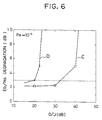
- Fig. 6 is a graph of a signal to noise power ratio degradation versus a desired to undesired signal power ratio for the low speed digital signals obtained by the same experiment using the digital communication system of Fig. 1 as that of Fig. 5.
- Fig. 7 is a graph of an available number of channels versus a desired to undesired signal power ratio for the low speed digital signals obtained by the same experiment using the digital communication system of Fig. 1 as that of Fig. 5.
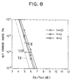
- Fig. 8 is a graph of a bit error rate versus a signal to noise power ratio for the high speed digital signals obtained by the same experiment using the digital communication system of Fig. 1 as that of Fig. 5.
-
- Referring now to Fig. 1, one embodiment of a digital communication system using superposed transmission of high speed and low speed digital signals according to the present invention will be described in detail.
- In this digital communication system, at a high speed
signal transmitting station 100, input high speed digital signals to be transmitted are entered from aninput terminal 1 at a speed of fd1 (bit/sec). - The entered high speed digital signals are then supplied to an FEC (Forward Error Correction)
encoder 2 for applying a convolutional encoding with an encoding rate of (n-1)/n, where n is a natural number. The encoded high speed digital signals are then applied with a serial-parallel conversion, and obtained I (In-phase) and Q (Quadrature) signals are then supplied at a speed ofoff filter 3 for applying a waveform shaping with a roll-off rate α (0 < α < 1). - At this point, at a point (a) indicated in Fig. 1, the high speed digital signals have a power spectrum as shown in Fig. 2A, with a frequency band equivalent to 2fb.
- A waveform shaped output of the roll-
off filter 3 is then supplied to a QPSK (Quadrature Phase Shift Keying)modulator 4 to make a quadrature modulation of a carrier in a frequency fc1 to obtain high speed QPSK signals. - On the other hand, at a low speed
signal transmitting station 110, input high speed input low speed digital signals to be transmitted are entered from aninput terminal 5 at a speed of fd2 (bit/sec), where fd2 < fd1. - The entered low speed digital signals are then supplied to an
FEC encoder 6 for applying a convolutional encoding with an encoding rate of (n'-1)/n', where n' is a natural number. The encoded low speed digital signals are then applied with serial-parallel conversion, and obtained I (In-phase) and Q (Quadrature) signals are then supplied to aspectrum spreader 7 at a speed of - At this point, at a point (b) indicated in Fig. 1, the low speed digital signals have a power spectrum as shown in Fig. 2B, with a frequency band equivalent to 2fb'.
- At the
spectrum spreader 7, the spectrum of the I and Q signals supplied from theFEC encoder 6 are spread to obtain SSMA (Spread Spectrum Multiple Access) signals. In this embodiment, as shown in Fig. 3, thespectrum spreader 7 is of a direct sequence type in which an output is obtained by multiplying an input directly with spectrum spreading codes at amultiplier 27. - The obtained SSMA signals are then supplied at a speed of fb to a roll-
off filter 8 for applying a waveform shaping with a roll-off rate α. At this point, at a point (c) indicated in Fig. 1, the SSMA signals have a power spectrum as shown in Fig. 2C, with a frequency band equivalent to 2fb. - A waveform shaped output of the roll-
off filter 8 is then supplied to aQPSK modulator 9 to make a quadrature modulation of a carrier in a frequency fc2 to obtain SSMA-QPSK signals. - The high speed QPSK signals and the SSMA-QPSK signals obtained by the
QPSK modulators signal transmitter device 51 provided at the high speedsignal transmitter station 100 and a low speedsignal transmitter device 52 provided at the low speedsignal transmitter station 110, respectively, through aradio transmission path 14 by using an identical frequency band, such that the high speed and the low speed digital signals are superposed on theradio transmission path 14. - At this point, at a point (d) indicated in Fig. 1, the superposed high speed and low speed digital signals have power spectra as shown in Fig. 2D, with a frequency band equivalent to 2fb and a common central frequency fc. Here, the superposed high speed and low speed digital signals at the
radio transmission path 14 have the continuous wave (CW) power ratio of the high speed signals to the SSMA signals indicated as D/U (Desired to Undesired signal power ratio) in Fig. 2D. - At a
receiving station 200, the superposed high speed QPSK and SSMA-QPSK signals received from theradio transmission path 14 by a receiverstation receiver device 53 are entered into aQPSK demodulator 15 for demodulating the received superposed signals. - Then, on one hand, the demodulated output signals of the
QPSK demodulator 15 are supplied to anFEC decoder 16 for making the error correction on the demodulated output signals, which is a Viterbi decoder capable of decoding the high speed digital signals encoded by theFEC encoder 2, such that output high speed digital signals reproducing the input high speed digital signals are obtained at an output terminal 17, at a speed of fd1 which is the same as the speed of the input high speed digital signals. - On the other hand, the demodulated output signals of the
QPSK demodulator 15 are also supplied to a roll-off filter 18 for applying a waveform shaping with a roll-off rate α, and a waveform shaped output of the roll-off filter 18 is then supplied to aQPSK modulator 19 to make a quadrature modulation of a carrier in a frequency fc2, so as to obtain a replica of the high speed QPSK signals in the same amplitude as the high speed QPSK signals. - Then, the obtained replica of the high speed QPSK signals is supplied to a
phase shifter 20 for inverting a phase of this replica, and the phase inverted replica is supplied to apower combiner 21. Thepower combiner 21 is also supplied with the superposed high speed QPSK and SSMA-QPSK signals received from theradio transmission path 14, such that thepower combiner 21 combines the received superposed signals with the phase inverted replica, so as to cancel the high speed digital signals in the received superposed signals and extract the SSMA-QPSK signals in the received superposed signals. - The SSMA-QPSK signals obtained by the
power combiner 21 are then supplied to aspectrum despreader 22 for despreading the spectrum of the SSMA-QPSK signals. This spectrum despreader 22 carries out an inverse operation of the spectrum spreading operation made by thespectrum spreader 7. Then, the spectrum despread output signals obtained by thespectrum despreader 22 are supplied to aQPSK demodulator 23 for demodulating the spectrum despread output signals. - Finally, the demodulated output signals of the
QPSK demodulator 23 are supplied to anFEC decoder 24 for making the error correction on the demodulated output signals, which is a Viterbi decoder capable of decoding the low speed digital signals encoded by theFEC encoder 6, such that output low speed digital signals reproducing the input low speed digital signals are obtained at anoutput terminal 25, at a speed of fd2 which is the same as the speed of the input low speed digital signals. - Fig. 1 also shows a
noise source 26 for power combining a variable amount of noise to theradio transmission path 14, which was used in the experiment to be described below for the purpose of realizing the realistic transmission condition. - Thus, in this digital communication system, the low speed digital signals are transmitted by using the FEC and the SSMA mode through the identical frequency band as the high speed digital signals. Consequently, the transmission of the superposed high speed and low speed digital signals can be realized by using a single transponder, and the transmission of the SSMA signals can be made by using a low power SSPA (Solid State Power Amplifier) having a transmission power of less than 1 watt.
- In addition, the high speed digital signals which can potentially interfere with the SSMA signals are cancelled out in obtaining the output low speed digital signals by using the replica of the high speed digital signals. As a consequence, it becomes possible to increase a number of channels for the low speed digital signals, as will be fully explained below.
- Furthermore, in this digital communication system, it is possible to realize the transmission of the high speed digital signals and the low speed digital signals at the appropriate bit error rates for respective signals, even when a number of channels for the low speed digital signals is increased, as will also be fully explained below.
- Here, it is to be noted that the
FEC encoders FEC decoders - It is also to be noted that the roll-
off filters - It is also to be noted that the QPSK modulation used in this embodiment may be replaced by BPSK (Binary Phase Shift Keying) modulation.
- It is also to be noted that the
spectrum spreader 7 and thespectrum despreader 22 may use the spectrum spreading other than the direct sequence type used in this embodiment, such as a frequency hopping type. - It is also to be noted that the reception of the superposed high speed and low speed digital signals from the
radio transmission path 14 can be made by using any desired detection mode including a coherent detection and a differential detection. - It is also to be noted that the
radio transmission path 14 may be replaced by other types of transmission path such as an optical fiber transmission path, if desired. - It is also to be noted that, for a case in which the transmitting station receives a backward low speed digital signals such as an answer-back voice signals from the receiving station while transmitting the high speed signals such as video signals to the receiving station, the configuration of a digital communication system of Fig. 1 as described above may be modified as shown in Fig. 4. This alternative configuration shown in Fig. 4 differs from the configuration of Fig. 1 in that the high speed signal transmitting part and the low speed signal receiving part are commonly included in a transmitting
station 150, in which the input of the roll-off filter 18 is provided by the output of theFEC encoder 2, instead of the output of theQPSK demodulator 15, and the SSMA-QPSK signals transmitted from the low speedsignal transmitting station 110 through thetransmission path 14 are received by a transmittingstation receiver device 54 provided at the transmittingstation 150 while the high speed QPSK signals transmitted from the transmittingstation 150 are received by areceiver device 55 provided at a receivingstation 210. - Referring now to Fig. 5 to Fig. 8, the result of the experiment conducted by using the digital communication system of Fig. 1 will be described. In the following, the reason why it is possible to increase a number of channels for the low speed digital signals in this digital communication system will be fully explained in a course of analyzing the result of the experiment. In addition, the reason why it is possible to realize the transmission of the high speed digital signals and the low speed digital signals at the appropriate bit error rates for respective signals in this digital communication system will also be fully explained in a course of analyzing the result of the experiment.
- As already mentioned above, the experiment was conducted by using the
noise source 26 shown in Fig. 1 for power combining a variable amount of noise to theradio transmission path 14, for the purpose of realizing the realistic transmission condition. - The other conditions used in the experiment are as follows.
- The speed fd1 of the input high speed digital signals entered at the
input terminal 1 was fd1 = 10.752 Mbit/sec. - The roll-off rate α of the roll-
off filters - The FEC encoding used by the
FEC encoder 2 was the convolutional encoding with the encoding rate R = 7/8, and the constraint length K = 7, and the FEC decoding used by theFEC decoder 16 was the 3 bit soft decision Viterbi decoding. - The speed fd2 of the input low speed digital signals entered at the
input terminal 5 was fd2 = 6.4 Kbit/sec. - The spectrum spreading used by the
spectrum spreader 7 and thespectrum despreader 22 was the direct sequence type with the spectrum spreading code speed of fss = 6.144 Mbit/sec. - The FEC encoding used by the
FEC encoder 6 was the convolutional encoding with the encoding rate R = 1/2, and the constraint length K = 7, and the FEC decoding used by theFEC decoder 24 was the 3 bit soft decision Viterbi decoding. - The result of this experiment is summarized in the graphs of Fig. 5 to Fig. 8, which will now be analyzed in detail.
- Fig. 5 shows the bit error rate Pe for the low speed digital signals transmitted between the
input terminal 5 and theoutput terminal 25, as a function of the signal to noise power ratio Eb/No, which was measured by varying the amount of noise combined from thenoise source 26. - In Fig. 5, a curve A indicates the result of this experiment using the digital communication system of the embodiment described above for a case of transmitting two channels of the low speed digital signals with the D/U ratio of the high speed digital signals with respect to the low speed digital signals equal to 25 dB. For a comparison, Fig. 5 also shows a curve B which indicates a comparative result for a case of transmitting two channels of the low speed digital signals with the D/U ratio of the high speed digital signals with respect to the low speed digital signals equal to 25 dB, by using only the FEC without the cancellation of the high speed digital signals using the replica. In addition, as a reference, Fig. 5 also shows a curve T1 which indicates a theoretical value for a case of transmitting only one channel of the low speed digital signals by using only the FEC without spectrum spreading.
- By comparing the curves A and B shown in Fig. 5, it can be seen that, in order to achieve the bit error rate of Pe = 10-4, the Eb/No degradation from the theoretical value indicated by the curve T1 is approximately 2.5 dB for the curve A while it is approximately 16 dB for the curve B, so that the Eb/No degradation necessary to achieve the bit error rate of Pe = 10-4 can be reduced by approximately 13.5 dB in the digital communication system of the embodiment described above.
- Next, Fig. 6 shows the Eb/No degradation from the theoretical value indicated by the curve T1 shown in Fig. 5 necessary to achieve the bit error rate of Pe = 10-4, as a function of the D/U ratio of the high speed digital signals with respect to the low speed digital signals.
- In Fig. 6, a curve C indicates the result of this experiment using the digital communication system of the embodiment described above for a case of transmitting two channels of the low speed digital signals. For a comparison, Fig. 6 also shows a curve D which indicates a comparative result for a case of transmitting two channels of the low speed digital signals by using only the FEC without the cancellation of the high speed digital signals using the replica.
- By comparing the curves C and D shown in Fig. 6, it can be seen that, for a practically tolerable Eb/No degradation of 3.0 dB in a case of realizing the bit error rate of Pe = 10-4, the D/U ratio can take a value up to approximately 30 dB for the curve C while it is only up to approximately 20 dB for the curve D, so that the D/U ratio available in a case of achieving the bit error rate of Pe = 10-4 with the Eb/No degradation from the theoretical value equal to 3.0 dB can be increased by approximately 10 dB in the digital communication system of the embodiment described above.
- Next, Fig. 7 shows the number of channels available for the low speed digital signals, for a constant total transmission power for the low speed digital signals equal to that required in a case of transmitting two channels of the low speed digital signals with the D/U ratio equal to 20 dB, as a function of the D/U ratio. As shown in Fig. 7, when the larger D/U ratio is used, the necessary transmission power for the low speed digital signals per channel becomes smaller, so that the number of channels available for the low speed digital signals can be increased for the same total transmission power. In a case of the digital communication system of the embodiment described above, the D/U ratio available in a case of achieving the bit error rate of Pe = 10-4 with the Eb/No degradation from the theoretical value equal to 3.0 dB can be increased by approximately 10 dB, up to approximately 30 dB, as shown in Fig. 6 described above, so that the number of channels available for the low speed digital signals can be increased ten times, up to approximately 20 channels.
- Lastly, Fig. 8 shows the bit error rate Pe for the high speed digital signals transmitted between the
input terminal 1 and the output terminal 17, as a function of the signal to noise power ratio Eb/No, which was measured by varying the amount of noise combined from thenoise source 26. - In Fig. 8, a curve E indicates the result of this experiment using the digital communication system of the embodiment described above for three cases of using the number of channels N of the low speed digital signals equal to 2, 6, and 20. As a reference, Fig. 8 also shows a curve T2 which indicates a theoretical value for a case without spectrum spreading which only uses the FEC for the high speed digital signals. From these curves E and T2, it can be seen that the Eb/No degradation from the theoretical value indicated by the curve T2 for a case of achieving the bit error rate of Pe = 10-4 is only approximately 1.0 dB for all three cases shown in Fig. 8, including the case of N = 20. Thus, it can be seen that the practically reasonable bit error rate performance can be achieved in the digital communication system of the embodiment described above even when 20 channels of the low speed digital signals are used.
- As described, according to the present invention, the high speed digital signals are cancelled out in obtaining the output low speed digital signals by using the replica of the high speed digital signals, so that it becomes possible to increase a number of channels for the low speed digital signals, while achieving the practically reasonable bit error rate performances for both the high speed digital signals and the low speed digital signals.
- This digital communication system according to the present invention will be particularly effective as a satellite video communication system which fully uses digital satellite transmissions for all the signal transmissions involved, because it becomes possible to economize a practical implementation of the satellite video communication system by improving the flexibility in setting up of a new small earth station,
- It is to be noted that, besides those already mentioned above, many modifications and variations of the above embodiment may be made without departing from the novel and advantageous features of the present invention. Accordingly, all such modifications and variations are intended to be included within the scope of the appended claims.
Claims (27)
- A method of superposed transmission of high and low speed digital signals in a digital communication system, comprising the steps of:(a1) forward error correction encoding high speed digital signals to be transmitted to obtain encoded high speed digital signals;(a2) modulating a first carrier in a first frequency with the encoded high speed digital signals obtained at the step (a1) to obtain modulated high speed signals;(b1) forward error correction encoding low speed digital signals to be transmitted to obtain encoded low speed digital signals;(b2) spreading a spectrum of the encoded low speed digital signals obtained at the step (b1) to obtain spread spectrum signals;(b3) modulating a second carrier in a second frequency with the spread spectrum signals obtained at the step (b2) to obtain modulated spread spectrum signals;(c) transmitting the modulated high speed signals obtained at the step (a2) and the modulated spread spectrum signals obtained at the step (b3) through an identical frequency band on a transmission path in a form of superposed transmission signals;(d1) demodulating the modulated high speed signals in the superposed transmission signals transmitted through the transmission path at the step (c) to reproduce the encoded high speed digital signals;(d2) forward error correction decoding the encoded high speed digital signals reproduced at the step (d1) to reproduce the high speed digital signals;(e1) obtaining a phase inverted replica of the modulated high speed signals in the superposed transmission signals transmitted through the transmission path at the step (c) according to the high speed digital signals reproduced at the step (d2);(e2) power combining the superposed transmission signals transmitted through the transmission path at the step (c) with the phase inverted replica obtained at the step (e1) to obtain modulated spread spectrum signals in the superposed transmission signals;(f1) despreading a spectrum of the modulated spread spectrum signals obtained at the step (e2) to obtain modulated low speed signals;(f2) demodulating the modulated low speed signals obtained at the step (f1) to reproduce the encoded low speed digital signals; and(f3) forward error correction decoding the encoded low speed digital signals reproduced at the step (f2) to reproduce the low speed digital signals.
- The method of claim 1, wherein at the step (a2), the first carrier in the first frequency is modulated by any one of a QPSK (Quadrature Phase Shift Keying) modulation and a BPSK (Binary Phase Shift Keying) modulation.
- The method of claim 1, wherein at the step (a1) and (d2), the forward error correction encoding and decoding use any one of convolutional codes, Reed-Solomon codes, and BCH codes.
- The method of claim 1, wherein at the steps (b2) and (f1), the spectrum is spread and despread by spectrum spreading and despreading, respectively, in any one of a direct sequence type using spectrum spreading codes and a frequency hopping type.
- The method of claim 1, wherein at the step (b1) and (f3), the forward error correction encoding and decoding use any one of convolutional codes, Reed-Solomon codes, and BCH codes.
- The method of claim 1, wherein at the step (b3), the second carrier in the second frequency is modulated by any one of a QPSK (Quadrature Phase Shift Keying) modulation and a BPSK (Binary Phase Shift Keying) modulation.
- The method of claim 1, wherein at the step (d1), the modulated high speed signals are demodulated by using any one of a coherent detection and a differential detection.
- The method of claim 1, wherein the step (e1) further comprises the steps of:(e11) modulating the second carrier in the second frequency with the high speed digital signals reproduced at the step (d2) to obtain a replica of the modulated high speed signals in the superposed transmission signals transmitted through the transmission path at the step (c); and(e12) inverting a phase of the replica obtained at the step (e11) to obtain the phase inverted replica of the modulated high speed signals in the superposed transmission signals transmitted through the transmission path at the step (c).
- The method of claim 10, wherein at the step (f1), the second carrier in the second frequency is modulated by any one of a QPSK (Quadrature Phase Shift Keying) modulation and a BPSK (Binary Phase Shift Keying) modulation.
- The method of claim 1, wherein at the step (f2), the modulated low speed signals are demodulated by using any one of a coherent detection and a differential detection.
- A digital communication system using superposed transmission of high and low speed digital signals, comprising:receiver means (54) for receiving modulated high speed signals and modulated spread spectrum signals through an identical frequency band on a transmission path (14) in a form of superposed transmission signals;first demodulator means (15) for demodulating the modulated high speed signals in the superposed transmission signals transmitted through the transmission path and received by the receiver means (54) to obtain encoded high speed digital signals;first decoder means (16) for forward error correction decoding the encoded high speed digital signals obtained by the first demodulator means to obtain high speed digital signals;replica generation means (18, 19, 20) for obtaining a phase inverted replica of the modulated high speed signals in the superposed transmission signals transmitted through the transmission path and received by the receiver means according to the high speed digital signals obtained by the first decoder means;power combiner means (21) for power combining the superposed transmission signals transmitted through the transmission path (14) and received by the receiver means (53) with the phase inverted replica obtained by the replica generation means (18, 19, 20) to obtain modulated spread spectrum signals in the superposed transmission signals;spectrum despreader means (22) for despreading a spectrum of the modulated spread spectrum signals obtained by the power combiner means (21) to obtain modulated low speed signals;second demodulator means (23) for demodulating the modulated low speed signals obtained by the spectrum despreader means (22) to obtain encoded low speed digital signals; andsecond decoder means (24) for forward error correction decoding the encoded low speed digital signals obtained by the second demodulator means (23) to obtain low speed digital signals.
- The digital communication system of claim 11, further comprising:first encoder means (2) for forward error correction encoding the high speed digital signals to obtain the encoded high speed digital signals;first modulator means (4) for modulating a first carrier in a first frequency with the encoded high speed digital signals obtained by the first encoder means (2) to obtain the modulated high speed signals to be transmitted through the transmission path (14);second encoder means (6) for forward error correction encoding the low speed digital signals to obtain the encoded low speed digital signals;spectrum spreader means (7) for spreading a spectrum of the encoded low speed digital signals obtained by the second encoder means (6) to obtain spread spectrum signals;second modulator means (9) for modulating a second carrier in a second frequency with the spread spectrum signals obtained by the spectrum spreader means (7) to obtain the modulated spread spectrum signals to be transmitted through the transmission path (14); andtransmitter means (51, 52) for transmitting the modulated high speed signals obtained by the first modulator means (4) and the modulated spread spectrum signals obtained by the second modulator means (9) through an identical frequency band on the transmission path (14) in a form of superposed transmission signals.
- The digital communication system of claim 12, wherein the first modulator means (4) modulates the first carrier in the first frequency by any one of a QPSK (Quadrature Phase Shift Keying) modulation and a BPSK (Binary Phase Shift Keying) modulation.
- The digital communication system of claim 12, wherein the first encoder means (2) and the first decoder means (16) use the forward error correction encoding and decoding, respectively, using any one of convolutional codes, Reed-Solomon codes, and BCH codes.
- The digital communication system of claim 12, wherein the spectrum spreader means (7) and the spectrum despreader (22) means use spectrum spreading and despreading, respectively, in any one of a direct sequence type using spectrum spreading codes and a frequency hopping type.
- The digital communication system of claim 12, wherein the second encoder means (6) and second decoder means (24) use the forward error correction encoding and decoding, respectively, using any one of convolutional codes, Reed-Solomon codes, and BCH codes.
- The digital communication system of claim 12, wherein the second modulator means (9) modulates the second carrier in the second frequency by any one of a QPSK (Quadrature Phase Shift Keying) modulation and a BPSK (Binary Phase Shift Keying) modulation.
- The digital communication system of claim 11, wherein the first demodulator means (15) demodulates the modulated high speed signals by using any one of a coherent detection and a differential detection.
- The digital communication system of claim 11, wherein the replica generation means (18, 19, 20) further comprises:modulator means (19) for modulating the second carrier in the second frequency with the high speed digital signals obtained by the first decoder means (15) to obtain a replica of the modulated high speed signals in the superposed transmission signals transmitted through the transmission path (14) and received by the receiver means (53); andphase shifter means (20) for inverting a phase of the replica obtained by the modulator means (19) to obtain the phase inverted replica of the modulated high speed signals in the superposed transmission signals transmitted through the transmission path (14) and received by the receiver means (53).
- The digital communication system of claim 19, wherein the modulator means (19) modulates the second carrier in the second frequency by any one of a QPSK (Quadrature Phase Shift Keying) modulation and a BPSK (Binary Phase Shift Keying) modulation.
- The digital communication system of claim 11, wherein the second demodulator means (23) demodulates the modulated low speed signals by using any one of a coherent detection and a differential detection.
- An apparatus for superposed transmission of high and low speed digital signals, comprising:first encoder means (2) for forward error correction encoding high speed digital signals to be transmitted to obtain encoded high speed digital signals;first modulator means (4) for modulating a first carrier in a first frequency with the encoded high speed digital signals obtained by the first encoder means (2) to obtain modulated high speed signals to be transmitted through a transmission path (14);second encoder means (6) for forwarding error correction encoding low speed digital signals to be transmitted to obtain encoded low speed digital signals;spectrum spreader means (7) for spreading a spectrum of the encoded low speed digital signals obtained by the second encoder means (6) to obtain spread spectrum signals;second modulator means (9) for modulating a second carrier in a second frequency with the spread spectrum signals obtained by the spectrum spreader means (7) to obtain modulated spread spectrum signals to be transmitted through the transmission path (14); andtransmitter means (51, 52) for transmitting the modulated high speed signals obtained by the first modulator means (4) and the modulated spread spectrum signals obtained by the second modulator means (9) through an identical frequency band on the transmission path (14) in a form of superposed transmission signals.
- The apparatus of claim 22, wherein the first modulator means (4) modulates the first carrier in the first frequency by any one of a QPSK (Quadrature Phase Shift Keying) modulation and a BPSK (Binary Phase Shift Keying) modulation.
- The apparatus of claim 22, wherein the first encoder means (2) uses the forward error correction encoding using any one of convolutional codes, Reed-Solomon codes, and BCH codes.
- The apparatus of claim 22, wherein the spectrum spreader means (7) uses spectrum spreading in any one of a direct sequence type using spectrum spreading codes and a frequency hopping type.
- The apparatus of claim 22, wherein the second encoder means (6) uses the forward error correction encoding using any one of convolutional codes, Reed-Solomon codes, and BCH codes.
- The apparatus of claim 22, wherein the second modulator means (9) modulates the second carrier in the second frequency by any one of a QPSK (Quadrature Phase Shift Keying) modulation and a BPSK (Binary Phase Shift Keying) modulation.
Applications Claiming Priority (3)
| Application Number | Priority Date | Filing Date | Title |
|---|---|---|---|
| JP310782/91 | 1991-11-26 | ||
| JP31078291 | 1991-11-26 | ||
| JP31078291A JP2554219B2 (en) | 1991-11-26 | 1991-11-26 | Digital signal superposition transmission method |
Publications (3)
| Publication Number | Publication Date |
|---|---|
| EP0545225A2 EP0545225A2 (en) | 1993-06-09 |
| EP0545225A3 EP0545225A3 (en) | 1994-04-13 |
| EP0545225B1 true EP0545225B1 (en) | 2000-02-09 |
Family
ID=18009406
Family Applications (1)
| Application Number | Title | Priority Date | Filing Date |
|---|---|---|---|
| EP19920119979 Expired - Lifetime EP0545225B1 (en) | 1991-11-26 | 1992-11-24 | Digital communication system using superposed transmission of high speed and low speed digital signals |
Country Status (5)
| Country | Link |
|---|---|
| US (1) | US5280537A (en) |
| EP (1) | EP0545225B1 (en) |
| JP (1) | JP2554219B2 (en) |
| CA (1) | CA2083776C (en) |
| DE (1) | DE69230663T2 (en) |
Families Citing this family (144)
| Publication number | Priority date | Publication date | Assignee | Title |
|---|---|---|---|---|
| US5887020A (en) | 1991-05-13 | 1999-03-23 | Omnipoint Corporation | Multi-band, multi-mode spread-spectrum communication system |
| US5796772A (en) | 1991-05-13 | 1998-08-18 | Omnipoint Corporation | Multi-band, multi-mode spread-spectrum communication system |
| US5694414A (en) | 1991-05-13 | 1997-12-02 | Omnipoint Corporation | Multi-band, multi-mode spread-spectrum communication system |
| US5815525A (en) | 1991-05-13 | 1998-09-29 | Omnipoint Corporation | Multi-band, multi-mode spread-spectrum communication system |
| US5790587A (en) | 1991-05-13 | 1998-08-04 | Omnipoint Corporation | Multi-band, multi-mode spread-spectrum communication system |
| JP3766434B2 (en) | 1991-12-16 | 2006-04-12 | ザーカム ワイヤレス, インコーポレイテッド | Spread spectrum data transmission system |
| GB2269075B (en) * | 1992-07-24 | 1996-04-10 | Roke Manor Research | Improvements in or relating to mobile cellular radio systems |
| US5721788A (en) | 1992-07-31 | 1998-02-24 | Corbis Corporation | Method and system for digital image signatures |
| US5465396A (en) | 1993-01-12 | 1995-11-07 | Usa Digital Radio Partners, L.P. | In-band on-channel digital broadcasting |
| IL111469A0 (en) * | 1993-11-01 | 1994-12-29 | Omnipoint Corp | Despreading/demodulating direct sequence spread spectrum signals |
| US6088590A (en) | 1993-11-01 | 2000-07-11 | Omnipoint Corporation | Method and system for mobile controlled handoff and link maintenance in spread spectrum communication |
| US6094575A (en) | 1993-11-01 | 2000-07-25 | Omnipoint Corporation | Communication system and method |
| US5436941A (en) * | 1993-11-01 | 1995-07-25 | Omnipoint Corporation | Spread spectrum spectral density techniques |
| US6005856A (en) | 1993-11-01 | 1999-12-21 | Omnipoint Corporation | Communication protocol for spread spectrum wireless communication system |
| US5841886A (en) | 1993-11-18 | 1998-11-24 | Digimarc Corporation | Security system for photographic identification |
| US7171016B1 (en) | 1993-11-18 | 2007-01-30 | Digimarc Corporation | Method for monitoring internet dissemination of image, video and/or audio files |
| US5710834A (en) * | 1995-05-08 | 1998-01-20 | Digimarc Corporation | Method and apparatus responsive to a code signal conveyed through a graphic image |
| US6983051B1 (en) * | 1993-11-18 | 2006-01-03 | Digimarc Corporation | Methods for audio watermarking and decoding |
| ATE199469T1 (en) | 1993-11-18 | 2001-03-15 | Digimarc Corp | VIDEO COPY CONTROL WITH VARIOUS EMBEDDED SIGNALS |
| US6122403A (en) | 1995-07-27 | 2000-09-19 | Digimarc Corporation | Computer system linked by using information in data objects |
| US6449377B1 (en) * | 1995-05-08 | 2002-09-10 | Digimarc Corporation | Methods and systems for watermark processing of line art images |
| US5748763A (en) | 1993-11-18 | 1998-05-05 | Digimarc Corporation | Image steganography system featuring perceptually adaptive and globally scalable signal embedding |
| US6574350B1 (en) | 1995-05-08 | 2003-06-03 | Digimarc Corporation | Digital watermarking employing both frail and robust watermarks |
| US6757406B2 (en) | 1993-11-18 | 2004-06-29 | Digimarc Corporation | Steganographic image processing |
| US5636292C1 (en) | 1995-05-08 | 2002-06-18 | Digimarc Corp | Steganography methods employing embedded calibration data |
| US6681028B2 (en) | 1995-07-27 | 2004-01-20 | Digimarc Corporation | Paper-based control of computer systems |
| US5862260A (en) | 1993-11-18 | 1999-01-19 | Digimarc Corporation | Methods for surveying dissemination of proprietary empirical data |
| US5822436A (en) | 1996-04-25 | 1998-10-13 | Digimarc Corporation | Photographic products and methods employing embedded information |
| US6611607B1 (en) | 1993-11-18 | 2003-08-26 | Digimarc Corporation | Integrating digital watermarks in multimedia content |
| US5841978A (en) | 1993-11-18 | 1998-11-24 | Digimarc Corporation | Network linking method using steganographically embedded data objects |
| US5748783A (en) | 1995-05-08 | 1998-05-05 | Digimarc Corporation | Method and apparatus for robust information coding |
| US6408082B1 (en) | 1996-04-25 | 2002-06-18 | Digimarc Corporation | Watermark detection using a fourier mellin transform |
| US6424725B1 (en) | 1996-05-16 | 2002-07-23 | Digimarc Corporation | Determining transformations of media signals with embedded code signals |
| US6614914B1 (en) | 1995-05-08 | 2003-09-02 | Digimarc Corporation | Watermark embedder and reader |
| US6944298B1 (en) * | 1993-11-18 | 2005-09-13 | Digimare Corporation | Steganographic encoding and decoding of auxiliary codes in media signals |
| US6516079B1 (en) | 2000-02-14 | 2003-02-04 | Digimarc Corporation | Digital watermark screening and detecting strategies |
| US5832119C1 (en) | 1993-11-18 | 2002-03-05 | Digimarc Corp | Methods for controlling systems using control signals embedded in empirical data |
| US5768426A (en) | 1993-11-18 | 1998-06-16 | Digimarc Corporation | Graphics processing system employing embedded code signals |
| US5490148A (en) * | 1993-12-15 | 1996-02-06 | Motorola, Inc. | Bit error rate estimator |
| US6869023B2 (en) * | 2002-02-12 | 2005-03-22 | Digimarc Corporation | Linking documents through digital watermarking |
| US6968057B2 (en) * | 1994-03-17 | 2005-11-22 | Digimarc Corporation | Emulsion products and imagery employing steganography |
| US6522770B1 (en) | 1999-05-19 | 2003-02-18 | Digimarc Corporation | Management of documents and other objects using optical devices |
| US6993152B2 (en) * | 1994-03-17 | 2006-01-31 | Digimarc Corporation | Hiding geo-location data through arrangement of objects |
| US7039214B2 (en) * | 1999-11-05 | 2006-05-02 | Digimarc Corporation | Embedding watermark components during separate printing stages |
| US5546420A (en) * | 1994-04-29 | 1996-08-13 | At&T Corp. | Methods of and devices for enhancing communications that use spread spectrum technology by using variable code techniques |
| CA2145566C (en) * | 1994-04-29 | 1999-12-28 | Nambirajan Seshadri | Methods of and devices for enhancing communications that use spread spectrum technology |
| JP2877248B2 (en) * | 1994-05-20 | 1999-03-31 | エヌ・ティ・ティ移動通信網株式会社 | Transmission power control method and apparatus in CDMA system |
| US5495468A (en) * | 1994-06-10 | 1996-02-27 | Linkplus Corporation | System and method for transmitting plural information waveforms over a single communications channel using lincompex techniques |
| US5956624A (en) | 1994-07-12 | 1999-09-21 | Usa Digital Radio Partners Lp | Method and system for simultaneously broadcasting and receiving digital and analog signals |
| IL114471A0 (en) * | 1994-07-12 | 1996-01-31 | Usa Digital Radio Partners L P | Method and system for simultaneously broadcasting and analog signals |
| US5648982A (en) | 1994-09-09 | 1997-07-15 | Omnipoint Corporation | Spread spectrum transmitter |
| US5610940A (en) | 1994-09-09 | 1997-03-11 | Omnipoint Corporation | Method and apparatus for noncoherent reception and correlation of a continous phase modulated signal |
| US5757847A (en) | 1994-09-09 | 1998-05-26 | Omnipoint Corporation | Method and apparatus for decoding a phase encoded signal |
| US5953370A (en) | 1994-09-09 | 1999-09-14 | Omnipoint Corporation | Apparatus for receiving and correlating a spread spectrum signal |
| US5754584A (en) | 1994-09-09 | 1998-05-19 | Omnipoint Corporation | Non-coherent spread-spectrum continuous-phase modulation communication system |
| US5832028A (en) | 1994-09-09 | 1998-11-03 | Omnipoint Corporation | Method and apparatus for coherent serial correlation of a spread spectrum signal |
| US5627856A (en) | 1994-09-09 | 1997-05-06 | Omnipoint Corporation | Method and apparatus for receiving and despreading a continuous phase-modulated spread spectrum signal using self-synchronizing correlators |
| US5680414A (en) | 1994-09-09 | 1997-10-21 | Omnipoint Corporation | Synchronization apparatus and method for spread spectrum receiver |
| US5692007A (en) | 1994-09-09 | 1997-11-25 | Omnipoint Corporation | Method and apparatus for differential phase encoding and decoding in spread-spectrum communication systems with continuous-phase modulation |
| US5881100A (en) | 1994-09-09 | 1999-03-09 | Omnipoint Corporation | Method and apparatus for coherent correlation of a spread spectrum signal |
| US5754585A (en) | 1994-09-09 | 1998-05-19 | Omnipoint Corporation | Method and apparatus for serial noncoherent correlation of a spread spectrum signal |
| US5659574A (en) | 1994-09-09 | 1997-08-19 | Omnipoint Corporation | Multi-bit correlation of continuous phase modulated signals |
| US5856998A (en) | 1994-09-09 | 1999-01-05 | Omnipoint Corporation | Method and apparatus for correlating a continuous phase modulated spread spectrum signal |
| US5963586A (en) | 1994-09-09 | 1999-10-05 | Omnipoint Corporation | Method and apparatus for parallel noncoherent correlation of a spread spectrum signal |
| US5629956A (en) | 1994-09-09 | 1997-05-13 | Omnipoint Corporation | Method and apparatus for reception and noncoherent serial correlation of a continuous phase modulated signal |
| US7724919B2 (en) * | 1994-10-21 | 2010-05-25 | Digimarc Corporation | Methods and systems for steganographic processing |
| US6535618B1 (en) * | 1994-10-21 | 2003-03-18 | Digimarc Corporation | Image capture device with steganographic data embedding |
| US6560349B1 (en) | 1994-10-21 | 2003-05-06 | Digimarc Corporation | Audio monitoring using steganographic information |
| US5742583A (en) * | 1994-11-03 | 1998-04-21 | Omnipoint Corporation | Antenna diversity techniques |
| MY121893A (en) * | 1995-04-28 | 2006-03-31 | Qualcomm Inc | Method and apparatus for providing variable rate data in a communications system using statistical multiplexing. |
| US7486799B2 (en) * | 1995-05-08 | 2009-02-03 | Digimarc Corporation | Methods for monitoring audio and images on the internet |
| US6721440B2 (en) | 1995-05-08 | 2004-04-13 | Digimarc Corporation | Low visibility watermarks using an out-of-phase color |
| US6760463B2 (en) | 1995-05-08 | 2004-07-06 | Digimarc Corporation | Watermarking methods and media |
| US6744906B2 (en) | 1995-05-08 | 2004-06-01 | Digimarc Corporation | Methods and systems using multiple watermarks |
| US6590996B1 (en) | 2000-02-14 | 2003-07-08 | Digimarc Corporation | Color adaptive watermarking |
| US5745484A (en) * | 1995-06-05 | 1998-04-28 | Omnipoint Corporation | Efficient communication system using time division multiplexing and timing adjustment control |
| US6356607B1 (en) | 1995-06-05 | 2002-03-12 | Omnipoint Corporation | Preamble code structure and detection method and apparatus |
| ZA965340B (en) * | 1995-06-30 | 1997-01-27 | Interdigital Tech Corp | Code division multiple access (cdma) communication system |
| US7020111B2 (en) * | 1996-06-27 | 2006-03-28 | Interdigital Technology Corporation | System for using rapid acquisition spreading codes for spread-spectrum communications |
| CA2154298C (en) * | 1995-07-20 | 2002-06-18 | Robert S. Hannebauer | Spread spectrum data communicator |
| US6788800B1 (en) | 2000-07-25 | 2004-09-07 | Digimarc Corporation | Authenticating objects using embedded data |
| US6408331B1 (en) * | 1995-07-27 | 2002-06-18 | Digimarc Corporation | Computer linking methods using encoded graphics |
| US6577746B1 (en) * | 1999-12-28 | 2003-06-10 | Digimarc Corporation | Watermark-based object linking and embedding |
| US6829368B2 (en) | 2000-01-26 | 2004-12-07 | Digimarc Corporation | Establishing and interacting with on-line media collections using identifiers in media signals |
| US6411725B1 (en) | 1995-07-27 | 2002-06-25 | Digimarc Corporation | Watermark enabled video objects |
| JPH09153918A (en) * | 1995-11-30 | 1997-06-10 | Nippon Telegr & Teleph Corp <Ntt> | Digital transmitter |
| US5761209A (en) * | 1996-03-15 | 1998-06-02 | Nec Corporation | Method of transmitting digital signals, transmitter and receiver used therefor |
| JPH09261201A (en) * | 1996-03-19 | 1997-10-03 | Hitachi Denshi Ltd | Spread spectrum transmission system |
| US7412072B2 (en) * | 1996-05-16 | 2008-08-12 | Digimarc Corporation | Variable message coding protocols for encoding auxiliary data in media signals |
| US6381341B1 (en) | 1996-05-16 | 2002-04-30 | Digimarc Corporation | Watermark encoding method exploiting biases inherent in original signal |
| US5859840A (en) * | 1996-05-31 | 1999-01-12 | Qualcomm Incorporated | Spread spectrum communication system which defines channel groups comprising selected channels that are additional to a primary channel and transmits group messages during call set up |
| US6094415A (en) * | 1996-06-20 | 2000-07-25 | Lockheed Martin Corporation | Vector division multiple access communication system |
| FR2752345A1 (en) * | 1996-08-08 | 1998-02-13 | Europ Agence Spatiale | Satellite transmission system for TV, data and telephony applications |
| US6496543B1 (en) * | 1996-10-29 | 2002-12-17 | Qualcomm Incorporated | Method and apparatus for providing high speed data communications in a cellular environment |
| US6141373A (en) | 1996-11-15 | 2000-10-31 | Omnipoint Corporation | Preamble code structure and detection method and apparatus |
| US6173007B1 (en) | 1997-01-15 | 2001-01-09 | Qualcomm Inc. | High-data-rate supplemental channel for CDMA telecommunications system |
| US7751370B2 (en) | 2001-07-13 | 2010-07-06 | Qualcomm Incorporated | Method and apparatus for forward link rate scheduling |
| US6335922B1 (en) | 1997-02-11 | 2002-01-01 | Qualcomm Incorporated | Method and apparatus for forward link rate scheduling |
| US6005898A (en) * | 1997-03-12 | 1999-12-21 | Interdigital Technology Corporation | Multichannel viterbi decoder |
| US20060262832A1 (en) * | 1997-03-12 | 2006-11-23 | Interdigital Technology Corporation | Convolutionally encoding and decoding multiple data streams |
| US6404828B2 (en) | 1997-03-12 | 2002-06-11 | Interdigital Technology Corporation | Multichannel decoder |
| US6282228B1 (en) | 1997-03-20 | 2001-08-28 | Xircom, Inc. | Spread spectrum codes for use in communication |
| JPH1175165A (en) | 1997-08-29 | 1999-03-16 | Sony Corp | Detection method and device for spread spectrum signal |
| JPH1188848A (en) | 1997-09-02 | 1999-03-30 | Sony Corp | Method and system for superimposing and transmitting additional information, device for superimposing and detecting additional information and storage medium |
| EP0901282B1 (en) | 1997-09-03 | 2006-06-28 | Hitachi, Ltd. | Method for recording and reproducing electronic watermark information |
| US20020051434A1 (en) * | 1997-10-23 | 2002-05-02 | Ozluturk Fatih M. | Method for using rapid acquisition spreading codes for spread-spectrum communications |
| US9118387B2 (en) | 1997-11-03 | 2015-08-25 | Qualcomm Incorporated | Pilot reference transmission for a wireless communication system |
| US6574211B2 (en) | 1997-11-03 | 2003-06-03 | Qualcomm Incorporated | Method and apparatus for high rate packet data transmission |
| US7184426B2 (en) * | 2002-12-12 | 2007-02-27 | Qualcomm, Incorporated | Method and apparatus for burst pilot for a time division multiplex system |
| US7054463B2 (en) | 1998-01-20 | 2006-05-30 | Digimarc Corporation | Data encoding using frail watermarks |
| US6275509B1 (en) | 1998-05-14 | 2001-08-14 | The United States Of America As Represented By The Secretary Of The Navy | Masked signal transceiver |
| JP3362009B2 (en) * | 1999-03-01 | 2003-01-07 | シャープ株式会社 | Spread spectrum communication equipment |
| US8064409B1 (en) | 1999-08-25 | 2011-11-22 | Qualcomm Incorporated | Method and apparatus using a multi-carrier forward link in a wireless communication system |
| US6621804B1 (en) | 1999-10-07 | 2003-09-16 | Qualcomm Incorporated | Method and apparatus for predicting favored supplemental channel transmission slots using transmission power measurements of a fundamental channel |
| US6608919B1 (en) * | 1999-11-10 | 2003-08-19 | Digimarc Corporation | Method and apparatus for encoding paper with information |
| US6625297B1 (en) * | 2000-02-10 | 2003-09-23 | Digimarc Corporation | Self-orienting watermarks |
| US6804377B2 (en) | 2000-04-19 | 2004-10-12 | Digimarc Corporation | Detecting information hidden out-of-phase in color channels |
| US7068683B1 (en) | 2000-10-25 | 2006-06-27 | Qualcomm, Incorporated | Method and apparatus for high rate packet data and low delay data transmissions |
| US6973098B1 (en) * | 2000-10-25 | 2005-12-06 | Qualcomm, Incorporated | Method and apparatus for determining a data rate in a high rate packet data wireless communications system |
| US7061510B2 (en) | 2001-03-05 | 2006-06-13 | Digimarc Corporation | Geo-referencing of aerial imagery using embedded image identifiers and cross-referenced data sets |
| US9363409B2 (en) * | 2001-03-05 | 2016-06-07 | Digimarc Corporation | Image management system and methods using digital watermarks |
| US7197160B2 (en) * | 2001-03-05 | 2007-03-27 | Digimarc Corporation | Geographic information systems using digital watermarks |
| US6950519B2 (en) * | 2001-03-05 | 2005-09-27 | Digimarc Corporation | Geographically watermarked imagery and methods |
| US7042470B2 (en) | 2001-03-05 | 2006-05-09 | Digimarc Corporation | Using embedded steganographic identifiers in segmented areas of geographic images and characteristics corresponding to imagery data derived from aerial platforms |
| US7254249B2 (en) * | 2001-03-05 | 2007-08-07 | Digimarc Corporation | Embedding location data in video |
| US7249257B2 (en) | 2001-03-05 | 2007-07-24 | Digimarc Corporation | Digitally watermarked maps and signs and related navigational tools |
| US8457346B2 (en) | 2001-04-24 | 2013-06-04 | Digimarc Corporation | Digital watermarking image signals on-chip |
| US6907093B2 (en) | 2001-08-08 | 2005-06-14 | Viasat, Inc. | Method and apparatus for relayed communication using band-pass signals for self-interference cancellation |
| JP3997890B2 (en) | 2001-11-13 | 2007-10-24 | 松下電器産業株式会社 | Transmission method and transmission apparatus |
| US6725017B2 (en) | 2001-12-05 | 2004-04-20 | Viasat, Inc. | Multi-channel self-interference cancellation method and apparatus for relayed communication |
| PT1456810E (en) | 2001-12-18 | 2011-07-25 | L 1 Secure Credentialing Inc | Multiple image security features for identification documents and methods of making same |
| US7728048B2 (en) * | 2002-12-20 | 2010-06-01 | L-1 Secure Credentialing, Inc. | Increasing thermal conductivity of host polymer used with laser engraving methods and compositions |
| US7694887B2 (en) * | 2001-12-24 | 2010-04-13 | L-1 Secure Credentialing, Inc. | Optically variable personalized indicia for identification documents |
| EP1459239B1 (en) * | 2001-12-24 | 2012-04-04 | L-1 Secure Credentialing, Inc. | Covert variable information on id documents and methods of making same |
| EP1459246B1 (en) * | 2001-12-24 | 2012-05-02 | L-1 Secure Credentialing, Inc. | Method for full color laser marking of id documents |
| US6996164B1 (en) | 2002-01-15 | 2006-02-07 | Viasat, Inc. | Self-interference removal using converter compensation in a relayed communication system |
| US7824029B2 (en) | 2002-05-10 | 2010-11-02 | L-1 Secure Credentialing, Inc. | Identification card printer-assembler for over the counter card issuing |
| US7804982B2 (en) | 2002-11-26 | 2010-09-28 | L-1 Secure Credentialing, Inc. | Systems and methods for managing and detecting fraud in image databases used with identification documents |
| US7712673B2 (en) | 2002-12-18 | 2010-05-11 | L-L Secure Credentialing, Inc. | Identification document with three dimensional image of bearer |
| DE602004030434D1 (en) | 2003-04-16 | 2011-01-20 | L 1 Secure Credentialing Inc | THREE-DIMENSIONAL DATA STORAGE |
| US7744002B2 (en) * | 2004-03-11 | 2010-06-29 | L-1 Secure Credentialing, Inc. | Tamper evident adhesive and identification document including same |
| US8140848B2 (en) | 2004-07-01 | 2012-03-20 | Digimarc Corporation | Digital watermark key generation |
| US20070177654A1 (en) * | 2006-01-31 | 2007-08-02 | Vladimir Levitine | Detecting signal carriers of multiple types of signals in radio frequency input for amplification |
| US8811200B2 (en) * | 2009-09-22 | 2014-08-19 | Qualcomm Incorporated | Physical layer metrics to support adaptive station-dependent channel state information feedback rate in multi-user communication systems |
Family Cites Families (22)
| Publication number | Priority date | Publication date | Assignee | Title |
|---|---|---|---|---|
| US32905A (en) * | 1861-07-23 | Daniel B Waite | Watch and socket rim | |
| US3752921A (en) * | 1970-11-04 | 1973-08-14 | Ibm | Distinct complex signals formed by plural clipping transformations of superposed isochronal pulse code sequences |
| JPS5824060B2 (en) * | 1979-06-08 | 1983-05-19 | 日本電信電話株式会社 | Audio band multiplex transmission method |
| US4355399A (en) * | 1981-02-23 | 1982-10-19 | Bell Telephone Laboratories, Incorporated | Adaptive spread spectrum FH-MFSK transmitter and receiver |
| US4425661A (en) * | 1981-09-03 | 1984-01-10 | Applied Spectrum Technologies, Inc. | Data under voice communications system |
| US4495620A (en) * | 1982-08-05 | 1985-01-22 | At&T Bell Laboratories | Transmitting data on the phase of speech |
| US4761796A (en) * | 1985-01-24 | 1988-08-02 | Itt Defense Communications | High frequency spread spectrum communication system terminal |
| DE3587962T2 (en) * | 1985-06-05 | 1995-05-24 | Fumio Ikegami | Digital transmission system with reduced bit error rate. |
| US4748636A (en) * | 1986-04-28 | 1988-05-31 | Nec Corporation | Method and apparatus of transmitting image data in a satellite system |
| JPS62254529A (en) * | 1986-04-28 | 1987-11-06 | Nec Corp | Data transmission system in satellite system |
| CA1318402C (en) * | 1986-05-16 | 1993-05-25 | Kouzou Kage | Signal communication capable of avoiding an audible reproduction of a sequency of information signals |
| DE3644168A1 (en) * | 1986-12-23 | 1988-07-14 | Messerschmitt Boelkow Blohm | Method for data transmission via satellite by means of spread spectra and small ground stations |
| DE3644174A1 (en) * | 1986-12-23 | 1988-07-14 | Messerschmitt Boelkow Blohm | Method for transmitting information via satellites |
| CA1293999C (en) * | 1987-08-24 | 1992-01-07 | Osamu Ichiyoshi | Earth station capable of effectively using a frequency band of asatellite |
| JPS6451837A (en) * | 1987-08-24 | 1989-02-28 | Nec Corp | Small sized earth station |
| JPS6465473A (en) * | 1987-09-04 | 1989-03-10 | Nec Corp | Satellite communication and position measurement system for moving body |
| FR2630871B1 (en) * | 1988-04-29 | 1994-03-18 | Alcatel Cit | METHOD AND DEVICE FOR ADDING AND SEPARATING A LOW-RATE DIGITAL CHANNEL TO THE HIGH-RATE DIGITAL CHANNEL OF A TRANSMISSION LINK |
| US5022046A (en) * | 1989-04-14 | 1991-06-04 | The United States Of America As Represented By The Secretary Of The Air Force | Narrowband/wideband packet data communication system |
| US5036513A (en) * | 1989-06-21 | 1991-07-30 | Academy Of Applied Science | Method of and apparatus for integrated voice (audio) communication simultaneously with "under voice" user-transparent digital data between telephone instruments |
| US5136592A (en) * | 1989-06-28 | 1992-08-04 | Digital Equipment Corporation | Error detection and correction system for long burst errors |
| DE3935911A1 (en) * | 1989-10-27 | 1991-05-02 | Deutsche Forsch Luft Raumfahrt | METHOD FOR RECEIVING BIT DETECTION OF DIFFERENTIALLY CODED BINARY OR QUATERIAL PSK SIGNALS IN DIFFERENTIALLY COHERENT DEMODULATION |
| JPH03179923A (en) * | 1989-12-08 | 1991-08-05 | Matsushita Electric Ind Co Ltd | Method and device for decoding bch code |
-
1991
- 1991-11-26 JP JP31078291A patent/JP2554219B2/en not_active Expired - Lifetime
-
1992
- 1992-11-24 EP EP19920119979 patent/EP0545225B1/en not_active Expired - Lifetime
- 1992-11-24 US US07/980,919 patent/US5280537A/en not_active Expired - Lifetime
- 1992-11-24 DE DE1992630663 patent/DE69230663T2/en not_active Expired - Lifetime
- 1992-11-25 CA CA 2083776 patent/CA2083776C/en not_active Expired - Lifetime
Also Published As
| Publication number | Publication date |
|---|---|
| EP0545225A3 (en) | 1994-04-13 |
| EP0545225A2 (en) | 1993-06-09 |
| US5280537A (en) | 1994-01-18 |
| JPH05153086A (en) | 1993-06-18 |
| CA2083776A1 (en) | 1993-05-27 |
| JP2554219B2 (en) | 1996-11-13 |
| CA2083776C (en) | 1998-09-29 |
| DE69230663T2 (en) | 2000-07-06 |
| DE69230663D1 (en) | 2000-03-16 |
Similar Documents
| Publication | Publication Date | Title |
|---|---|---|
| EP0545225B1 (en) | Digital communication system using superposed transmission of high speed and low speed digital signals | |
| US5325394A (en) | Method and apparatus for canceling spread-spectrum noise | |
| US10110298B2 (en) | Techniques for providing broadcast services on spot beam satellites | |
| US5327455A (en) | Method and device for multiplexing data signals | |
| US5105435A (en) | Method and apparatus for cancelling spread-spectrum noise | |
| US5235612A (en) | Method and apparatus for cancelling spread-spectrum noise | |
| US5687166A (en) | Modulation system for spread spectrum CDMA communication | |
| US6553018B1 (en) | Method and apparatus for adjusting transmission power of a CDMA terminal | |
| US6396823B1 (en) | Base station transceiver for frequency hopping code division multiple access system | |
| JPH08506715A (en) | Composite waveform forming method and apparatus | |
| JPS6242537B2 (en) | ||
| KR19980087458A (en) | Transmission Method of Two Parallel Channels Using Code Division and Apparatus Implementing The Method | |
| US5668795A (en) | Modulation system for spread spectrum CDMA communiction | |
| EP0869623A2 (en) | Method and apparatus for spectrally efficient transmission of CDMA modulated signals | |
| US7031397B1 (en) | Communication system with reduced power variation and method therefor | |
| US6301310B1 (en) | Efficient implementation for systems using CEOQPSK | |
| EP0903871A2 (en) | Spread spectrum signal generating device and method | |
| Sugiyama et al. | A Frequency Utilization Ffficiency Improvement on Superposed SSMA-QPSK Signal Transmission over High Speed QPSK Signals in Nonlinear Channels | |
| Kato et al. | Novel satellite digital video TDMA system for business video communications | |
| Sugiyama et al. | Burst mode interference cancellation for superposed transmission of SSMA-QPSK signals and TDMA-QPSK signals in nonlinear channels | |
| US7139302B2 (en) | Code division multiple access enhanced capacity system | |
| Morikura et al. | SSMA signal transmission over QPSK modulated signal | |
| ENOMOTO et al. | Common Transmission of High Speed QPSK Signals and SSMA Signals over Non-linearly Amplified Transponder | |
| US20030066015A1 (en) | System for synchronising a multiple access digital telecommunication system | |
| JP3201444B2 (en) | Digital signal superimposition transmission method |
Legal Events
| Date | Code | Title | Description |
|---|---|---|---|
| PUAI | Public reference made under article 153(3) epc to a published international application that has entered the european phase |
Free format text: ORIGINAL CODE: 0009012 |
|
| 17P | Request for examination filed |
Effective date: 19921124 |
|
| AK | Designated contracting states |
Kind code of ref document: A2 Designated state(s): DE FR GB |
|
| PUAL | Search report despatched |
Free format text: ORIGINAL CODE: 0009013 |
|
| AK | Designated contracting states |
Kind code of ref document: A3 Designated state(s): DE FR GB |
|
| RAP1 | Party data changed (applicant data changed or rights of an application transferred) |
Owner name: NIPPON TELEGRAPH AND TELEPHONE CORPORATION |
|
| 17Q | First examination report despatched |
Effective date: 19970108 |
|
| GRAG | Despatch of communication of intention to grant |
Free format text: ORIGINAL CODE: EPIDOS AGRA |
|
| GRAG | Despatch of communication of intention to grant |
Free format text: ORIGINAL CODE: EPIDOS AGRA |
|
| GRAH | Despatch of communication of intention to grant a patent |
Free format text: ORIGINAL CODE: EPIDOS IGRA |
|
| GRAH | Despatch of communication of intention to grant a patent |
Free format text: ORIGINAL CODE: EPIDOS IGRA |
|
| GRAA | (expected) grant |
Free format text: ORIGINAL CODE: 0009210 |
|
| AK | Designated contracting states |
Kind code of ref document: B1 Designated state(s): DE FR GB |
|
| REF | Corresponds to: |
Ref document number: 69230663 Country of ref document: DE Date of ref document: 20000316 |
|
| ET | Fr: translation filed | ||
| PLBE | No opposition filed within time limit |
Free format text: ORIGINAL CODE: 0009261 |
|
| STAA | Information on the status of an ep patent application or granted ep patent |
Free format text: STATUS: NO OPPOSITION FILED WITHIN TIME LIMIT |
|
| 26N | No opposition filed | ||
| REG | Reference to a national code |
Ref country code: GB Ref legal event code: IF02 |
|
| PGFP | Annual fee paid to national office [announced via postgrant information from national office to epo] |
Ref country code: DE Payment date: 20101123 Year of fee payment: 19 |
|
| PGFP | Annual fee paid to national office [announced via postgrant information from national office to epo] |
Ref country code: GB Payment date: 20101020 Year of fee payment: 19 |
|
| PGFP | Annual fee paid to national office [announced via postgrant information from national office to epo] |
Ref country code: FR Payment date: 20111201 Year of fee payment: 20 |
|
| REG | Reference to a national code |
Ref country code: DE Ref legal event code: R071 Ref document number: 69230663 Country of ref document: DE |
|
| REG | Reference to a national code |
Ref country code: DE Ref legal event code: R071 Ref document number: 69230663 Country of ref document: DE |
|
| REG | Reference to a national code |
Ref country code: GB Ref legal event code: PE20 Expiry date: 20121123 |
|
| PG25 | Lapsed in a contracting state [announced via postgrant information from national office to epo] |
Ref country code: GB Free format text: LAPSE BECAUSE OF EXPIRATION OF PROTECTION Effective date: 20121123 |