EP0543332A2 - System and method for adjusting white balance of projector type color display device - Google Patents
System and method for adjusting white balance of projector type color display device Download PDFInfo
- Publication number
- EP0543332A2 EP0543332A2 EP92119620A EP92119620A EP0543332A2 EP 0543332 A2 EP0543332 A2 EP 0543332A2 EP 92119620 A EP92119620 A EP 92119620A EP 92119620 A EP92119620 A EP 92119620A EP 0543332 A2 EP0543332 A2 EP 0543332A2
- Authority
- EP
- European Patent Office
- Prior art keywords
- screen
- cathode ray
- single color
- color
- ray tubes
- Prior art date
- Legal status (The legal status is an assumption and is not a legal conclusion. Google has not performed a legal analysis and makes no representation as to the accuracy of the status listed.)
- Granted
Links
Images

Classifications
-
- H—ELECTRICITY
- H04—ELECTRIC COMMUNICATION TECHNIQUE
- H04N—PICTORIAL COMMUNICATION, e.g. TELEVISION
- H04N9/00—Details of colour television systems
- H04N9/12—Picture reproducers
- H04N9/31—Projection devices for colour picture display, e.g. using electronic spatial light modulators [ESLM]
- H04N9/3179—Video signal processing therefor
- H04N9/3182—Colour adjustment, e.g. white balance, shading or gamut
-
- H—ELECTRICITY
- H04—ELECTRIC COMMUNICATION TECHNIQUE
- H04N—PICTORIAL COMMUNICATION, e.g. TELEVISION
- H04N9/00—Details of colour television systems
- H04N9/12—Picture reproducers
- H04N9/31—Projection devices for colour picture display, e.g. using electronic spatial light modulators [ESLM]
- H04N9/3191—Testing thereof
- H04N9/3194—Testing thereof including sensor feedback
-
- H—ELECTRICITY
- H04—ELECTRIC COMMUNICATION TECHNIQUE
- H04N—PICTORIAL COMMUNICATION, e.g. TELEVISION
- H04N9/00—Details of colour television systems
- H04N9/64—Circuits for processing colour signals
- H04N9/73—Colour balance circuits, e.g. white balance circuits or colour temperature control
Landscapes
- Engineering & Computer Science (AREA)
- Multimedia (AREA)
- Signal Processing (AREA)
- Processing Of Color Television Signals (AREA)
- Video Image Reproduction Devices For Color Tv Systems (AREA)
- Testing, Inspecting, Measuring Of Stereoscopic Televisions And Televisions (AREA)
Abstract
Description
- The present invention relates to a system and a method for adjusting the white balance of a projector type color display device.
- In color projectors (viz., projector type display devices), "white balance adjustment" is usually carried out at the time when the projectors are still in a manufacturing line and/or they are brought to a user's setting place. As is known, by properly adjusting the white balance of the color projector, the color image on the screen can have a natural color tone. However, in the color projectors of a type wherein images on display surfaces of three (viz., Red, Green and Blue) color display TV tubes are projected onto a screen to form a colored image thereon, the white or color balance of the projector is easily out of tune due to complicated arrangement of the three display TV tubes. Thus, in the color projectors of such type, the white balance adjustment is always necessary when the setting place and setting orientation of the projector change. Furthermore, such white balance adjustment becomes necessary when the projectors are used for a long time.
- Hitherto, the white balance adjustment at the manufacturing line has been made by using color sensors. That is, the color sensors are manually attached to the display faces of the three display tubes for sensing the colors displayed on the display faces. All white signals (such as 5IRE signal and 100IRE signal) are fed to each display tube as an external signal, and the white balance adjustment of the color projector is carried out with reference to the information signals issued from the color sensors. One of the methods of this type is described in Japanese Patent First Provisional Publication 3-236699.
- The white balance adjustment at the user side has been made by using a colorimeter and a color-difference meter. That is, the adjustment has been made manually by an inspector who compares, with his or her eyes, the color image on the screen and the reference color data provided by the colorimeter and the color difference meter.
- However, it is difficult or at least troublesome to adjust the white balance by using the above-mentioned conventional adjusting methods. In fact, attaching and detaching the color sensors to and from the display tubes on the manufacturing line are troublesome. This becomes much severe when a plurality of stackable color display devices, which are used for consituting a so-called "multiscreen", are subjected to the white balance adjustment. Furthermore, the white balance adjustment by using the colorimeter and the color-difference meter requires a great deal of skill.
- It is therefore an object of the present invention to provide a system and a method for adjusting the white balance of a projector type color display device, which are free of the above-mentioned drawbacks.
- According to a first aspect of the present invention, there is provided a system for adjusting the white balance of a projector type color display device which includes three single color cathode ray tubes from which single color beams are projected onto a screen to form a colored image on the screen. The white balance adjusting system comprises first means for feeding one of the three cathode ray tubes with all white signal to cause the same to project a single color image on the screen; second means for detecting a luminance value of the single color image on the screen; third means for deriving luminance values of the other single color images from the detected luminance value; and fourth means for controlling the selected cathode ray tube in such a manner that the derived luminance values are put in a tolerance which is provided for dealing with a noise of the second means.
- According to a second aspect of the present invention, there is provided a method for adjusting the white balance of a projector type color display device which includes three single color cathode ray tubes from which single color beams are projected onto a screen to form a colored image on the screen. The method comprises (a) feeding one of the three cathode ray tubes with all white signal to cause the same to project a single color image on the screen; (b) detecting a luminance value of the single color image on the screen; (c) deriving luminance values of the other single color images from the detected luminance value; (d) controlling the selected cathode ray tube in such a manner that the derived luminance values are put into a tolerance which is provided for dealing with a noise which is inevitably produced when the step (b) is carried out; and (e) repeating the steps (a), (b), (c) and (e) on the other two cathode ray tubes.
- According to a third aspect of the present invention, there is provided a method for adjusting the white balance of a plurality of projector type color display devices, each device including three single color cathode ray tubes from which single color beams are projected onto a screen to form a colored image on the screen. The method comprises (a) preparing a reference color display device whose white balance has been already adjusted; (b) feeding one of the three cathode ray tubes of the reference color display device with all white signal to cause the same to project a single color image on the screen; (c) detecting a luminance value of the single color image on the screen; (d) repeating the steps (b) and (c) on the other two cathode ray tubes of the reference color display device thereby to respectively provide reference luminance values of the three cathode ray tubes of the reference color display device; (e) detecting luminance values of three single color images on the screen, which images are provided by the three cathode ray tubes of one of the plural color display devices to be adjusted; (f) controlling the gain and the bias of the selected color display device in such a manner that the detected luminance values are controlled to the reference luminance values; and (g) repeating the steps of (e) and (f) on the remaining color display devices.
-
- Other objects and advantages of the present invention will become apparent from the following description when taken in conjunction with the accompanying drawings, in which:
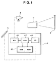
- Fig. 1 is a simplified block diagram of a white balance adjusting system for a projector type color display device, which is made in accordance with the present invention;
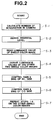
- Fig. 2 is a flowchart showing operation steps conducted in the system of Fig. 1 for adjusting the white balance of one color projector; and
- Fig. 3 is a flowchart showing operation steps conducted for adjusting the white balance of a plurality of color projectors.
- Referring to Fig. 1, there is shown a block diagram of a system for adjusting the white balance of one color projector, which is made in accordance with the present invention.
- In the drawing, denoted by numeral 1 is the color projector whose white balance is to be adjusted, 2 is a screen onto which a color image from the projector 1 is projected, and 3 is a black-and-white CCD (charged coupled device) camera which is arranged to face the
screen 2. - Designated by
numeral 4 is a projector auto-set up control unit and 5 is a commander. Thecontrol unit 4 is a microcomputer which comprises an A/D (analog/digital)converter section 41, a CPU (central processing unit)section 42, a RAM andROM section 43 and an I/O (input/output)section 44. - The projector 1 comprises three (viz., Red, Green and Blue) high intensity cathode ray tubes (viz., CRTs) from which respective (viz., Red, Green and blue) brilliant color beams are projected forward onto the
screen 2 to form a colored image on thescreen 2. - As will be described in detail hereinafter, upon requirement of the white balance adjustment of the color projector 1, at first, only one (for example, Green) cathode ray tube is energized and all white signal of H/L (high-light) side is fed to the Green cathode ray tube. Thus, the Green cathode ray tube projects a green color image (that is, the green component of the all white signal of H/L side) on the
screen 2. In response to an instruction signal from thecontrol unit 4, the black-and-white CCD camera 3 takes or detects the luminance (or brightness) of the green color image on thescreen 2. The analog signal from theCCD camera 3 is converted into a digital type by the A/D converter 41 and fed to theCPU 42. Then, all white signal of C/O (cut-off) side is fed to the Green cathode ray tube to cause the same to project another green color image (that is, the green component of all white signal of C/O side) on thescreen 2. TheCCD camera 3 detects the luminance value of this green color image on thescreen 2 to feed thecontrol unit 4 with an information on the luminance value. TheCPU 42 of thecontrol unit 4 treats the luminance representing data from theCCD camera 3 with reference to a predetermined reference data stored in thememory section 43 to provide a display means of thecommander 5 with an information which is needed for adjusting the Green cathode ray tube of the color projector 1. With reference to the information thus displayed on thecommander 5, an operator manipulates gain and bias volumes of the Green cathode ray tube. - Then, similar manipulation is applied to the other two (Red and Blue) cathode ray tubes for adjusting the white balance of these cathode ray tubes.
- With these steps, the white balance adjustment of the color projector 1 is completed.
- The method for adjusting the white balance of the color projector 1 will be much clearly understood from the following description.
- Referring to Fig. 2, there is shown a flowchart which depicts the steps for adjusting the white balance of the color projector 1.
- The ROM of the
control unit 4 has previously memorized reference luminance ratios between Green, Red and Blue color images on thescreen 2 on three reference color temperatures which are, for example, 6500.K, 3200.K and 9300.K. - The
CCD camera 3 has an integration function to deal with a dark picture on thescreen 2. - In the flowchart, at step S-1, the number of integration in the
CCD camera 3 on the H/L side and that on the C/O side are both calculated in accordance with the luminance values of single color (viz.,, green) images on thescreen 2, which images have the color temperature of 6500.K. As is described hereinabove, the two types of single (viz., green) color images are provided by feeding the Green cathode ray tube with all white signal of the H/L and C/O sides. Then, at step S-2, the pedestal level of the single color image (viz., the blanking level of the image signal produced when thescreen 2 does not prepare any luminous image thereon) is derived. Then, at step S-3, the luminance value of the single (viz., green) color image on thescreen 2 is read on each of the "H/L" and "C/O" sides. At step S-4, the luminance values of the other two (viz., Red and Blue) color images are derived from the just read luminance value of "Green" in view of the previously memorized luminance ratio between "G", "R" and "B" of the color temperature of 6500.K. At steps S-5 and S-6, by controlling the gain and the bias of the Green cathode ray tube, the tracking of the "H/L" side-and that of the "C/O" side are adjusted so that the derived luminance values of the two color images "B" and "R" are brought onto or hidden by a margin which is provided for dealing with the noise ofCCD camera 3. With this, adjustment of the Green cathode ray tube is achieved. - Then, similar steps are carried out on the other two (viz., red and blue) color images on the
screen 2, which images have the color temperature of 3200.K and 9300.K. These color images are provided by feeding the Red and Blue cathode ray tubes with all white signal of the H/L and C/O sides. When operation steps corresponding to the above-mentioned steps S-5 and S-6 are finished, adjustment of the Red and Blue cathode ray tubes is completed, and thus, the white balance of the color projector 1 is completed. - Referring to Fig. 3, there is shown another flowchart which depicts the steps for adjusting the white balance of a plurality of color projectors.
- In order to carry out this adjustment, a reference or first projector 1 is prepared, whose white balance has been already adjusted in the above-mentioned manner.
- At step S-11, the luminance values of the reference colors "R", "G" and "B" of the first projector 1 are detected on both the "H/L" and "C/O" sides. That is, at first, one of the Red, Green and Blue cathode ray tubes is energized and fed with all white signal of H/L and C/O sides. With this, the selected cathode ray tube projects one color image on the
screen 2. The luminance value of the color image is detected by the black-and-white CCD camera 3. Similar operation is carried out on the other two cathode ray tubes to detect the luminance values of the other two color images. With these steps, six reference luminance values "RH1", "GH1", "BH1", "RC1", "GC1" and "BC1" of the reference projector 1 are provided. - Then, at step S-12, by controlling gain and bias volumes of each cathode ray tube of a second projector 1' which is to be adjusted, the tracking of the "H/L" side and that of the "C/O" side are adjusted in such a manner that the luminance values "RH1-2", "GH1-2", "BH1-2", "RC1-2", "GC1-2" and "BC1-2" of this second projector 1' are the same as the reference luminance values "RH1", "GH1", "BH1", "RC1", "GC1" and "BC1" of the reference or first projector 1.
- At steps S-13 and S-14, similar operation is carried out for adjusting the white balance of third and fourth projectors 1" and 1"'.
- With these steps, adjustment of the white balance of the second, third and fourth projectors 1', 1" and 1"' and more can be readily carried out by using only the data of the first or reference projector 1.
- In the afore-mentioned embodiments, a black-and-white
type CCD camera 3 is used. However, if desired, a color type CCD camera may be used. In this case, all of the three cathode ray tubes project their single color images onto thescreen 2 at the same time to form all white image on thescreen 2, and the color CCD camera detects the luminance values of the Green, Red and Blue color components of the all white image at the same time.
Claims (11)
- A system for adjusting the white balance of a projector type color display device which includes three single color cathode ray tubes from which single color beams are projected onto a screen to form a colored image on the screen, the white balance adjusting system comprising:
first means for feeding one of the three cathode ray tubes with all white signal to cause the same to project a single color image on said screen;
second means for detecting a luminance value of said single color image on said screen;
third means for deriving luminance values of the other single color images from the detected luminance value; and
fourth means for controlling the selected cathode ray tube in such a manner that the derived luminance values are put in a tolerance which is provided for dealing with a noise of said second means. - A system as claimed in Claim 1, in which said first means feeds the selected cathode ray tube with both all white signal of high-light side and all white signal of cut-off side.
- A system as claimed in Claim 2, in which said second means comprises one of a black-and-white CCD camera and a color CCD camera.
- A system as claimed in Claim 3, in which said third means is a computer, said computer preparing a reference luminance ratio between green, red and blue color images on the screen on a reference color temperature, said reference luminance ratio being used when the luminance values of the other single color images are derived.
- A system as claimed in Claim 2, in which the CCD camera is arranged to face said screen.
- A system as claimed in Claim 1, further comprising a display means which displays an information needed for adjusting the gain and the bias of the selected cathode ray tube.
- A method for adjusting the white balance of a projector type color display device which includes three single color cathode ray tubes from which single color beams are projected onto a screen to form a colored image on the screen, said method comprising:(a) feeding one of the three cathode ray tubes with all white signal to cause the same to project a single color image on said screen;(b) detecting a luminance value of said single color image on said screen;(c) deriving luminance values of the other single color images from the detected luminance value;(d) controlling the selected cathode ray tube in such a manner that the derived luminance values are put into a tolerance which is provided for dealing with a noise which is inevitably produced when the step (b) is carried out; and(e) repeating the steps (a), (b), (c) and (e) on the other two cathode ray tubes.
- A method as claimed in Claim 7, in which the operation of the step (b) is made by using a black-and-white CCD camera.
- A method as claimed in Claim 7, in which the derivation of the luminance values of the other single color images is made with reference to a reference luminance ratio between green, red and blue color images on the screen on a reference color temperature.
- A method for adjusting the white balance of a plurality of projector type color display devices, each device including three single color cathode ray tubes from which single color beams are projected onto a screen to form a colored image on the screen,
said method comprising:(a) preparing a reference color display device whose white balance has been already adjusted;(b) feeding one of the three cathode ray tubes of said reference color display device with all white signal to cause the same to project a single color image on said screen;(c) detecting a luminance value of said single color image on said screen;(d) repeating the steps (b) and (c) on the other two cathode ray tubes of said reference color display device thereby to respectively provide reference luminance values of the three cathode ray tubes of the reference color display device;(e) detecting luminance values of three single color images on the screen, which images are provided by the three cathode ray tubes of one of the plural color display devices to be adjusted;(f) controlling the gain and the bias of the selected color display device in such a manner that the detected luminance values are controlled to the reference luminance values; and(g) repeating the steps of (e) and (f) on the remaining color display devices. - A method as claimed in Claim 10, in which the color display devices are to be stacked for consituting a multiscreen.
Applications Claiming Priority (2)
| Application Number | Priority Date | Filing Date | Title |
|---|---|---|---|
| JP03301915A JP3116472B2 (en) | 1991-11-18 | 1991-11-18 | White balance adjustment method |
| JP301915/91 | 1991-11-18 |
Publications (3)
| Publication Number | Publication Date |
|---|---|
| EP0543332A2 true EP0543332A2 (en) | 1993-05-26 |
| EP0543332A3 EP0543332A3 (en) | 1993-08-11 |
| EP0543332B1 EP0543332B1 (en) | 1998-01-21 |
Family
ID=17902647
Family Applications (1)
| Application Number | Title | Priority Date | Filing Date |
|---|---|---|---|
| EP92119620A Expired - Lifetime EP0543332B1 (en) | 1991-11-18 | 1992-11-17 | System and method for adjusting white balance of projector type color display device |
Country Status (4)
| Country | Link |
|---|---|
| US (1) | US5287173A (en) |
| EP (1) | EP0543332B1 (en) |
| JP (1) | JP3116472B2 (en) |
| DE (1) | DE69224153T2 (en) |
Cited By (3)
| Publication number | Priority date | Publication date | Assignee | Title |
|---|---|---|---|---|
| EP0989757A4 (en) * | 1998-04-15 | 2000-03-29 | Mitsubishi Electric Corp | Multivision system, color calibration method and display |
| EP1363462A2 (en) * | 2002-05-09 | 2003-11-19 | Seiko Epson Corporation | Image processing system, projector, information storage medium, and image processing method |
| EP1473933A2 (en) * | 2003-05-02 | 2004-11-03 | Seiko Epson Corporation | Image processing system, projector, information storage medium and image processing method |
Families Citing this family (13)
| Publication number | Priority date | Publication date | Assignee | Title |
|---|---|---|---|---|
| JP2899059B2 (en) * | 1990-04-27 | 1999-06-02 | キヤノン株式会社 | Projection television device |
| US5570140A (en) * | 1993-07-08 | 1996-10-29 | Mitsubishi Denki Kabushiki Kaisha | Projection unit for projection type display apparatus |
| JP3735158B2 (en) * | 1996-06-06 | 2006-01-18 | オリンパス株式会社 | Image projection system and image processing apparatus |
| CN1213426C (en) | 1999-08-31 | 2005-08-03 | 松下电器产业株式会社 | Disk reproducing system |
| JP3632574B2 (en) * | 2000-07-31 | 2005-03-23 | セイコーエプソン株式会社 | Environment-adaptive image display system and information storage medium |
| EP1185110B1 (en) * | 2000-08-31 | 2010-02-10 | Texas Instruments Incorporated | Automated color matching for tiled projection system |
| JP3719499B2 (en) * | 2000-09-13 | 2005-11-24 | セイコーエプソン株式会社 | Correction curve generation method, image processing method, image display apparatus, and recording medium |
| JP2002094822A (en) * | 2000-09-13 | 2002-03-29 | Seiko Epson Corp | Method for generating correction curve, method for processing image, image display unit and recording medium |
| JP3719411B2 (en) * | 2001-05-31 | 2005-11-24 | セイコーエプソン株式会社 | Image display system, projector, program, information storage medium, and image processing method |
| JP3755593B2 (en) * | 2002-03-26 | 2006-03-15 | セイコーエプソン株式会社 | Projection-type image display system, projector, program, information storage medium, and image processing method |
| CA2457248C (en) | 2003-02-07 | 2012-07-17 | Closure Medical Corporation | Applicators, dispensers and methods for dispensing and applying adhesive material |
| TWI336587B (en) * | 2007-06-12 | 2011-01-21 | Etron Technology Inc | Color calibrating method for setting target gamma curves of target display device |
| CN101655658B (en) * | 2008-08-20 | 2011-06-15 | 和硕联合科技股份有限公司 | Display device and chromatic aberration correcting and compensating method thereof |
Citations (7)
| Publication number | Priority date | Publication date | Assignee | Title |
|---|---|---|---|---|
| US3877068A (en) * | 1970-02-21 | 1975-04-08 | Minolta Camera Kk | Method and apparatus for controlling color balance of a color television system |
| US4485394A (en) * | 1982-09-27 | 1984-11-27 | General Electric Company | Automatic convergence and gray scale correction for television _receivers and projection television systems |
| US4962418A (en) * | 1987-06-30 | 1990-10-09 | Kabushiki Kaisha Toshiba | Color picture display apparatus |
| EP0440216A2 (en) * | 1990-01-30 | 1991-08-07 | Pioneer Electronic Corporation | White balance control system |
| EP0442685A1 (en) * | 1990-02-14 | 1991-08-21 | Sony Corporation | Method and system for measurement of characteristics of image display |
| WO1991015931A1 (en) * | 1990-04-09 | 1991-10-17 | Proxima Corporation | Stacked display panel construction and method of making same |
| JPH04285992A (en) * | 1991-03-15 | 1992-10-12 | Toshiba Corp | Multi-screen display device |
Family Cites Families (3)
| Publication number | Priority date | Publication date | Assignee | Title |
|---|---|---|---|---|
| US4599642A (en) * | 1984-03-02 | 1986-07-08 | Rca Corporation | Video signal processor with bias error compensation |
| JPS61161093A (en) * | 1985-01-09 | 1986-07-21 | Sony Corp | Device for correcting dynamic uniformity |
| JPH04367189A (en) * | 1991-06-13 | 1992-12-18 | Pioneer Electron Corp | White balance adjuster |
-
1991
- 1991-11-18 JP JP03301915A patent/JP3116472B2/en not_active Expired - Lifetime
-
1992
- 1992-11-17 DE DE69224153T patent/DE69224153T2/en not_active Expired - Fee Related
- 1992-11-17 EP EP92119620A patent/EP0543332B1/en not_active Expired - Lifetime
- 1992-11-18 US US07/978,367 patent/US5287173A/en not_active Expired - Lifetime
Patent Citations (7)
| Publication number | Priority date | Publication date | Assignee | Title |
|---|---|---|---|---|
| US3877068A (en) * | 1970-02-21 | 1975-04-08 | Minolta Camera Kk | Method and apparatus for controlling color balance of a color television system |
| US4485394A (en) * | 1982-09-27 | 1984-11-27 | General Electric Company | Automatic convergence and gray scale correction for television _receivers and projection television systems |
| US4962418A (en) * | 1987-06-30 | 1990-10-09 | Kabushiki Kaisha Toshiba | Color picture display apparatus |
| EP0440216A2 (en) * | 1990-01-30 | 1991-08-07 | Pioneer Electronic Corporation | White balance control system |
| EP0442685A1 (en) * | 1990-02-14 | 1991-08-21 | Sony Corporation | Method and system for measurement of characteristics of image display |
| WO1991015931A1 (en) * | 1990-04-09 | 1991-10-17 | Proxima Corporation | Stacked display panel construction and method of making same |
| JPH04285992A (en) * | 1991-03-15 | 1992-10-12 | Toshiba Corp | Multi-screen display device |
Non-Patent Citations (1)
| Title |
|---|
| PATENT ABSTRACTS OF JAPAN vol. 17, no. 84 (P-1490)19 February 1993 & JP-A-4 285 992 ( TOSHIBA CORP ) 12 October 1992 * |
Cited By (8)
| Publication number | Priority date | Publication date | Assignee | Title |
|---|---|---|---|---|
| EP0989757A4 (en) * | 1998-04-15 | 2000-03-29 | Mitsubishi Electric Corp | Multivision system, color calibration method and display |
| EP0989757A1 (en) * | 1998-04-15 | 2000-03-29 | Mitsubishi Denki Kabushiki Kaisha | Multivision system, color calibration method and display |
| US6340976B1 (en) | 1998-04-15 | 2002-01-22 | Mitsubishi Denki Kabushiki Kaisha | Multivision system, color calibration method and display |
| EP1363462A2 (en) * | 2002-05-09 | 2003-11-19 | Seiko Epson Corporation | Image processing system, projector, information storage medium, and image processing method |
| EP1363462A3 (en) * | 2002-05-09 | 2008-04-23 | Seiko Epson Corporation | Image processing system, projector, information storage medium, and image processing method |
| EP1473933A2 (en) * | 2003-05-02 | 2004-11-03 | Seiko Epson Corporation | Image processing system, projector, information storage medium and image processing method |
| EP1473933A3 (en) * | 2003-05-02 | 2005-02-02 | Seiko Epson Corporation | Image processing system, projector, information storage medium and image processing method |
| US7114813B2 (en) | 2003-05-02 | 2006-10-03 | Seiko Epson Corporation | Image processing system, projector, program, information storage medium and image processing method |
Also Published As
| Publication number | Publication date |
|---|---|
| EP0543332A3 (en) | 1993-08-11 |
| US5287173A (en) | 1994-02-15 |
| DE69224153T2 (en) | 1998-08-20 |
| EP0543332B1 (en) | 1998-01-21 |
| DE69224153D1 (en) | 1998-02-26 |
| JP3116472B2 (en) | 2000-12-11 |
| JPH05145956A (en) | 1993-06-11 |
Similar Documents
| Publication | Publication Date | Title |
|---|---|---|
| EP0543332B1 (en) | System and method for adjusting white balance of projector type color display device | |
| US6256062B1 (en) | Color correction apparatus for matching colors in a signal output from a first image apparatus with those from a second image apparatus | |
| EP0224904B1 (en) | White balance adjusting device of color video camera | |
| US5398058A (en) | Color image pickup device having color temperature converting filters | |
| US6075563A (en) | Electronic camera capable of adjusting color tone under different light sources | |
| US5289268A (en) | Apparatus using brightness information from a photometering circuit and a brightness-converted green component from a color metering circuit to ultimately adjust white balance | |
| US6822695B2 (en) | Surrounding light judging method and video compensation control apparatus using the same | |
| US6504952B1 (en) | Image processing method and apparatus | |
| US7284867B2 (en) | Projector | |
| US4608595A (en) | White balance correction for negative-to-positive conversion | |
| US5181103A (en) | White balance adjusting system for a color television system | |
| EP0505984A2 (en) | Color video still image processing system | |
| EP0395201B1 (en) | Component color bar alignment test signal | |
| US4635101A (en) | Image conversion apparatus for television signals | |
| US5508739A (en) | White-balance adjusting apparatus and a method thereof for a video camera | |
| US3689689A (en) | Circuit arrangement for color point adjustment | |
| US5301017A (en) | Apparatus for receiving and displaying color television signals having different formats | |
| KR100428522B1 (en) | White balance circuit for a video camera | |
| US4740820A (en) | Method of and apparatus for producing hard copy of color picture adaptive to variations in characteristics of fluorescent screen of recorder CRT | |
| EP0497412B1 (en) | Colour picture display device and colour camera | |
| EP0440216B1 (en) | White balance control system | |
| US5293224A (en) | White balance control system | |
| US4891691A (en) | Still image color sequential photographic apparatus | |
| EP0620692B1 (en) | Tint detection circuit | |
| US5208664A (en) | Image reading method and apparatus with coordination function between read value and original density |
Legal Events
| Date | Code | Title | Description |
|---|---|---|---|
| PUAI | Public reference made under article 153(3) epc to a published international application that has entered the european phase |
Free format text: ORIGINAL CODE: 0009012 |
|
| AK | Designated contracting states |
Kind code of ref document: A2 Designated state(s): DE FR GB |
|
| PUAL | Search report despatched |
Free format text: ORIGINAL CODE: 0009013 |
|
| AK | Designated contracting states |
Kind code of ref document: A3 Designated state(s): DE FR GB |
|
| 17P | Request for examination filed |
Effective date: 19940112 |
|
| 17Q | First examination report despatched |
Effective date: 19951221 |
|
| GRAG | Despatch of communication of intention to grant |
Free format text: ORIGINAL CODE: EPIDOS AGRA |
|
| GRAG | Despatch of communication of intention to grant |
Free format text: ORIGINAL CODE: EPIDOS AGRA |
|
| GRAH | Despatch of communication of intention to grant a patent |
Free format text: ORIGINAL CODE: EPIDOS IGRA |
|
| GRAH | Despatch of communication of intention to grant a patent |
Free format text: ORIGINAL CODE: EPIDOS IGRA |
|
| GRAA | (expected) grant |
Free format text: ORIGINAL CODE: 0009210 |
|
| AK | Designated contracting states |
Kind code of ref document: B1 Designated state(s): DE FR GB |
|
| REF | Corresponds to: |
Ref document number: 69224153 Country of ref document: DE Date of ref document: 19980226 |
|
| ET | Fr: translation filed | ||
| PLBE | No opposition filed within time limit |
Free format text: ORIGINAL CODE: 0009261 |
|
| STAA | Information on the status of an ep patent application or granted ep patent |
Free format text: STATUS: NO OPPOSITION FILED WITHIN TIME LIMIT |
|
| 26N | No opposition filed | ||
| PGFP | Annual fee paid to national office [announced via postgrant information from national office to epo] |
Ref country code: FR Payment date: 20011113 Year of fee payment: 10 |
|
| PGFP | Annual fee paid to national office [announced via postgrant information from national office to epo] |
Ref country code: GB Payment date: 20011121 Year of fee payment: 10 |
|
| PGFP | Annual fee paid to national office [announced via postgrant information from national office to epo] |
Ref country code: DE Payment date: 20011203 Year of fee payment: 10 |
|
| REG | Reference to a national code |
Ref country code: GB Ref legal event code: IF02 |
|
| PG25 | Lapsed in a contracting state [announced via postgrant information from national office to epo] |
Ref country code: GB Free format text: LAPSE BECAUSE OF NON-PAYMENT OF DUE FEES Effective date: 20021117 |
|
| PG25 | Lapsed in a contracting state [announced via postgrant information from national office to epo] |
Ref country code: DE Free format text: LAPSE BECAUSE OF NON-PAYMENT OF DUE FEES Effective date: 20030603 |
|
| GBPC | Gb: european patent ceased through non-payment of renewal fee | ||
| PG25 | Lapsed in a contracting state [announced via postgrant information from national office to epo] |
Ref country code: FR Free format text: LAPSE BECAUSE OF NON-PAYMENT OF DUE FEES Effective date: 20030731 |
|
| REG | Reference to a national code |
Ref country code: FR Ref legal event code: ST |