EP0541295A2 - Image processing apparatus - Google Patents
Image processing apparatus Download PDFInfo
- Publication number
- EP0541295A2 EP0541295A2 EP92309931A EP92309931A EP0541295A2 EP 0541295 A2 EP0541295 A2 EP 0541295A2 EP 92309931 A EP92309931 A EP 92309931A EP 92309931 A EP92309931 A EP 92309931A EP 0541295 A2 EP0541295 A2 EP 0541295A2
- Authority
- EP
- European Patent Office
- Prior art keywords
- data
- colour
- liquid crystal
- display
- image
- Prior art date
- Legal status (The legal status is an assumption and is not a legal conclusion. Google has not performed a legal analysis and makes no representation as to the accuracy of the status listed.)
- Granted
Links
Images


Classifications
-
- G—PHYSICS
- G09—EDUCATION; CRYPTOGRAPHY; DISPLAY; ADVERTISING; SEALS
- G09G—ARRANGEMENTS OR CIRCUITS FOR CONTROL OF INDICATING DEVICES USING STATIC MEANS TO PRESENT VARIABLE INFORMATION
- G09G3/00—Control arrangements or circuits, of interest only in connection with visual indicators other than cathode-ray tubes
- G09G3/20—Control arrangements or circuits, of interest only in connection with visual indicators other than cathode-ray tubes for presentation of an assembly of a number of characters, e.g. a page, by composing the assembly by combination of individual elements arranged in a matrix no fixed position being assigned to or needed to be assigned to the individual characters or partial characters
- G09G3/34—Control arrangements or circuits, of interest only in connection with visual indicators other than cathode-ray tubes for presentation of an assembly of a number of characters, e.g. a page, by composing the assembly by combination of individual elements arranged in a matrix no fixed position being assigned to or needed to be assigned to the individual characters or partial characters by control of light from an independent source
- G09G3/36—Control arrangements or circuits, of interest only in connection with visual indicators other than cathode-ray tubes for presentation of an assembly of a number of characters, e.g. a page, by composing the assembly by combination of individual elements arranged in a matrix no fixed position being assigned to or needed to be assigned to the individual characters or partial characters by control of light from an independent source using liquid crystals
- G09G3/3607—Control arrangements or circuits, of interest only in connection with visual indicators other than cathode-ray tubes for presentation of an assembly of a number of characters, e.g. a page, by composing the assembly by combination of individual elements arranged in a matrix no fixed position being assigned to or needed to be assigned to the individual characters or partial characters by control of light from an independent source using liquid crystals for displaying colours or for displaying grey scales with a specific pixel layout, e.g. using sub-pixels
-
- G—PHYSICS
- G09—EDUCATION; CRYPTOGRAPHY; DISPLAY; ADVERTISING; SEALS
- G09G—ARRANGEMENTS OR CIRCUITS FOR CONTROL OF INDICATING DEVICES USING STATIC MEANS TO PRESENT VARIABLE INFORMATION
- G09G2300/00—Aspects of the constitution of display devices
- G09G2300/04—Structural and physical details of display devices
- G09G2300/0439—Pixel structures
- G09G2300/0452—Details of colour pixel setup, e.g. pixel composed of a red, a blue and two green components
-
- G—PHYSICS
- G09—EDUCATION; CRYPTOGRAPHY; DISPLAY; ADVERTISING; SEALS
- G09G—ARRANGEMENTS OR CIRCUITS FOR CONTROL OF INDICATING DEVICES USING STATIC MEANS TO PRESENT VARIABLE INFORMATION
- G09G2340/00—Aspects of display data processing
- G09G2340/06—Colour space transformation
-
- G—PHYSICS
- G09—EDUCATION; CRYPTOGRAPHY; DISPLAY; ADVERTISING; SEALS
- G09G—ARRANGEMENTS OR CIRCUITS FOR CONTROL OF INDICATING DEVICES USING STATIC MEANS TO PRESENT VARIABLE INFORMATION
- G09G3/00—Control arrangements or circuits, of interest only in connection with visual indicators other than cathode-ray tubes
- G09G3/20—Control arrangements or circuits, of interest only in connection with visual indicators other than cathode-ray tubes for presentation of an assembly of a number of characters, e.g. a page, by composing the assembly by combination of individual elements arranged in a matrix no fixed position being assigned to or needed to be assigned to the individual characters or partial characters
- G09G3/2007—Display of intermediate tones
- G09G3/2044—Display of intermediate tones using dithering
- G09G3/2051—Display of intermediate tones using dithering with use of a spatial dither pattern
-
- G—PHYSICS
- G09—EDUCATION; CRYPTOGRAPHY; DISPLAY; ADVERTISING; SEALS
- G09G—ARRANGEMENTS OR CIRCUITS FOR CONTROL OF INDICATING DEVICES USING STATIC MEANS TO PRESENT VARIABLE INFORMATION
- G09G3/00—Control arrangements or circuits, of interest only in connection with visual indicators other than cathode-ray tubes
- G09G3/20—Control arrangements or circuits, of interest only in connection with visual indicators other than cathode-ray tubes for presentation of an assembly of a number of characters, e.g. a page, by composing the assembly by combination of individual elements arranged in a matrix no fixed position being assigned to or needed to be assigned to the individual characters or partial characters
- G09G3/2007—Display of intermediate tones
- G09G3/2059—Display of intermediate tones using error diffusion
-
- G—PHYSICS
- G09—EDUCATION; CRYPTOGRAPHY; DISPLAY; ADVERTISING; SEALS
- G09G—ARRANGEMENTS OR CIRCUITS FOR CONTROL OF INDICATING DEVICES USING STATIC MEANS TO PRESENT VARIABLE INFORMATION
- G09G3/00—Control arrangements or circuits, of interest only in connection with visual indicators other than cathode-ray tubes
- G09G3/20—Control arrangements or circuits, of interest only in connection with visual indicators other than cathode-ray tubes for presentation of an assembly of a number of characters, e.g. a page, by composing the assembly by combination of individual elements arranged in a matrix no fixed position being assigned to or needed to be assigned to the individual characters or partial characters
- G09G3/34—Control arrangements or circuits, of interest only in connection with visual indicators other than cathode-ray tubes for presentation of an assembly of a number of characters, e.g. a page, by composing the assembly by combination of individual elements arranged in a matrix no fixed position being assigned to or needed to be assigned to the individual characters or partial characters by control of light from an independent source
- G09G3/36—Control arrangements or circuits, of interest only in connection with visual indicators other than cathode-ray tubes for presentation of an assembly of a number of characters, e.g. a page, by composing the assembly by combination of individual elements arranged in a matrix no fixed position being assigned to or needed to be assigned to the individual characters or partial characters by control of light from an independent source using liquid crystals
- G09G3/3611—Control of matrices with row and column drivers
- G09G3/3622—Control of matrices with row and column drivers using a passive matrix
- G09G3/3629—Control of matrices with row and column drivers using a passive matrix using liquid crystals having memory effects, e.g. ferroelectric liquid crystals
Definitions
- This invention relates to an image processing apparatus which processes data for a colour image so as to display the colour image by a display device, such as a liquid crystal display.
- liquid crystal displays have been used as display devices of personal computers, word processors or televisions.
- bistable liquid crystal element has been proposed by Clark and Lagerwall (U.S. Patent 4,367,924).
- Ferroelectric liquid crystal having Chiral smectic C phase (Sm C *) or H phase (Sm H *) is usually used as the bistable liquid crystal.
- This liquid crystal has bistable states in an electric field, including a first optically stable state (first orientation state) and a second optically stable state (second orientation state). Accordingly, unlike an optical modulation element used in a TN (twist nematic) type liquid crystal, the liquid crystal is oriented in the first optically stable state for one electric field vector, and the liquid crystal is oriented in the second optically stable state for the other electric field vector.
- the liquid crystal of this type quickly responds to the applied electric field to assume one of the two stable states and maintains the state when the electric field is removed.
- bistable liquid crystal element has only two states, so a liquid crystal display which consists of such bistable liquid crystal cells cannot display a halftone image or a full colour image.
- the present invention has been made in the light of the above problems and its object is to provide an image processing apparatus and method which can display a colour image with rich colours.
- the present invention also provides an image processing apparatus and method which can display a full colour image by using a display device, of which each display element displays an image with at least two levels.
- the present invention also provides an image processing apparatus and method which can display a colour image having low brightness without the deterioration of the image quality.
- an image processing apparatus comprising extraction means for extracting white component data from colour data representing a colour image; generating means for generating colour display data on the basis of the colour data and the white component data, the colour display data including white display data; and display means for displaying a colour image in accordance with the colours display data, said display means displaying white pixels in accordance with the white display data.
- an image processing apparatus comprising extracting means for extracting white component data from colour data representing a colour image; suppressing means for suppressing the white component data; generating means for generating colour display data on the basis of the colour data and the suppressed white component data; and display means for displaying a colour image in accordance with the colour display data.
- an image processing apparatus comprising: input means for inputting multi-level colour data representing a colour image; pseud halftone processing means for performing on the multi-level colour data a pseud halftone process to express a halftone image by controlling the rate of pixels in a unit area, and display means for displaying a colour image in accordance with the colour data subjected to the pseud halftone process.
- an image processing apparatus comprising: input means for inputting colour data representing a colour image; processing means for processing the colour data to produce colour display data; and display means for displaying a colour image on the basis of the colour display data; characterised in that said display means displays the colour image using a plurality of two level pixels, and that said processing means produces the colour display data which expresses halftone images using the plurality of two level pixels.
- FIG. 1 shows a block diagram of an image processing apparatus embodying the present invention.
- the image processing apparatus comprises a minimum value detector 11, subtractors 13-1 - 13-3, pseud halftone processors 14-1 - 14-4 and a display 15. Red (R), Green (G) and Blue (B) colour data representing a colour image are inputted from an external device, such as a host computer, pixel by pixel.
- an external device such as a host computer
- the display 15 has a liquid crystal display panel which is composed of ferroelectric liquid crystal.
- 640 x 560 liquid crystal cells each of which can assume two states, i.e. a transparent state and an opaque state, are arranged in a matrix basis.
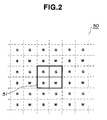
- FIG. 2 shows a part of the liquid crystal display panel 50.
- a basic unit 51 forms a pixel and consists of four liquid crystal cells, each state of which can be independently controlled. Namely, the four liquid crystal cells can transmit or shut off the light from the back of the liquid crystal display panel 50, respectively.
- the basic unit 51 can display sixteen colours shown in Figure 3 by controlling the states of the four liquid crystal cells, independently.
- the liquid crystal display panel 50 is provided with not only R,G,B filters but also W filters. Accordingly, it can display extra eight colours, such as light grey, light blue and so on, which cannot be displayed by using only R,G,B filters.
- liquid crystal display panel 50 On the liquid crystal display panel 50, twenty sets of basic unit 51 are arranged in one square millimetre. A colour displayed by each of such a small basic unit 51 cannot be recognised by human visual characteristics. Therefore, a colour composed of mixtures of colours of neighbouring dozens of pixels (basic units) can be recognised.
- the minimum value detector 11 detects a minimum value among the 8-bit R,G,B colour data supplied from a host computer via a data bus, pixel by pixel.
- the minimum value detected by the minimum value detector 11 is treated as W data which represents a white component.
- Min (R,G,B) is assumed as the W data
- R′,G′,B′ data which are used for driving the liquid crystal display panel 50
- the subtractors 13-1 - 13-3 subtract the W data, which obtained by the minimum value detector 11, from the R,G,B colour data, respectively, so as to generate the R′,G′,B′ data expressed in equations (1).
- the R′,G′,B′ data are multi-value data, so they cannot be directly used for driving the liquid crystal display panel 50, of which liquid crystal cells assume two states.
- the pseud halftone processors 14-1 - 14-4 perform the pseud halftone processes on the R′,G′,B′,W data, respectively, so as to convert them into binary driving data, i.e. R ⁇ ,G ⁇ ,B ⁇ ,W ⁇ data which correspond to the liquid crystal cells provided with the R,G,B,W filters.
- the pseud halftone processors 14-1 - 14-3 may perform the pseud halftone process, which expresses a halftone image by controlling the rate of pixels to be displayed in a unit area, in accordance with an error diffusion method, an ordered dither process and so on. Details of such methods are disclosed in U.S. Patent 4,958,218 and IEEE Transactions on Communications, Vol. Com-29, No.12, December 1981, pages 1898-1925 which are incorporated herein by reference.
- FIG. 5 is a block diagram of the pseud halftone processor 14-1.
- the R′ data is processed in accordance with the error diffusion method and the R′ data is assumed as image data Xij.
- image data Xij is added by an adder 81 to a value which is obtained by multiplying a weight coefficient ⁇ ij designated by a weighting circuit 82 to an error ⁇ ij (the difference between correction data X′ij which has previously been generated and output data Yij) stored in an error buffer memory 83.
- the adding process can be expressed by the following equation:
- Figure 6 shows an example of weight coefficients.
- * indicates a position of a pixel which is at present being processed.
- Yij is the data which was binarised into 1s or 0s.
- the binarised data is stored into an output buffer 87 and supplied to the display 15.
- the difference ⁇ ij between the correction data X′ij and the data Y′ij which is obtained by multiplying the data Yij output from the binarising circuit 84 by 255, is calculated by a calculator 85.
- the result from the calculator 85 is stored into an area at a position corresponding to a pixel position 86 in the error buffer memory 83.
- the pseud halftone processors 14-2 - 14-3 can be realised by the same construction as that of the pseud halftone processor 14-1 shown in Figure 5.
- the R ⁇ ,G ⁇ ,B ⁇ ,W ⁇ binary data obtained by the binarising process of the pseud halftone processors 14-1 - 14-4 are supplied to the display 15.
- Figure 7 shows the construction of the display 15.
- Line memories 41-1 - 41-4 store the R ⁇ ,G ⁇ ,B ⁇ ,W ⁇ binary data obtained by the pseud halftone process.
- a multiplexer 42 rearranges the R ⁇ ,G ⁇ ,B ⁇ ,W ⁇ binary data pixel by pixel, so as to arrange them in a data arrangement corresponding to that of the R,G,B,W filters shown in Figure 2.
- a frame memory 43 stores a frame of the R ⁇ ,G ⁇ ,B ⁇ ,W ⁇ binary data subjected to the rearrangement by the multiplexer 42.
- a display controller 44 reads out the R ⁇ ,G ⁇ ,B ⁇ ,W ⁇ binary data from the frame memory 43, line by line, and supplies them to a shift register 45 in a serial manner.
- the display controller 44 also supplies control signals to a line memory 46, a driver 47 and a decoder 48.
- the shift register 45 supplies a line of the R ⁇ ,G ⁇ ,B ⁇ ,W ⁇ binary data to the line memory 46 in parallel manner.
- the line memory 46 supplies the R ⁇ ,G ⁇ ,B ⁇ ,W ⁇ binary data to the driver 47 as binary signals indicating ON/OFF states of a line of the liquid crystal cells.
- the driver 47 drives each of the liquid crystal cells of the liquid crystal display panel 50 in response to the R ⁇ ,G ⁇ ,B ⁇ ,W ⁇ binary data from the line memory 46.
- the decoder 48 indicates a line to be driven.
- a driver 49 sequentially drives the liquid crystal cells of the liquid crystal display panel 50, line by line.
- each of 640x560 liquid crystal cells on the liquid crystal display panel 50 assumes either the transparent state or the opaque state in response to the R ⁇ ,G ⁇ ,B ⁇ ,W ⁇ data. Thereby, a full colour image represented by the R,G,B colour data is displayed on the liquid crystal display panel 50.
- the white component is extracted from the input R,G,B colour data, and full colour image display data, i.e. Red, Green, Blue and White display data, are formed on the basis of the extracted white component. Then a full colour image is displayed by the liquid crystal display panel, on which white filters are provided in addition to red, green, blue filters, in accordance with the Red, Green, Blue and White display data.
- full colour image display data i.e. Red, Green, Blue and White display data
- a full colour image can be displayed with rich colours by using the liquid crystal display panel, each liquid crystal cell of which displays binary image.
- the pseud halftone process such as an error diffusion method or an ordered dither process, is performed on the multi-level data representing a colour image, so as to obtain binary colour image data subjected to the pseud halftone process.
- a full colour image can be displayed by using the liquid crystal display panel, each liquid crystal cell of which assumes two states.
- the liquid crystal display panel 50 will now be described in detail.
- Chiral smectic liquid crystal having ferroelectric property is particularly suitable as a liquid crystal material used for the liquid crystal display panel 50.
- chiral smectic C phase (SmC*), chiral smectic G phase (Sm G*), chiral smectic F phase (Sm F*), chiral smectic I phase (Sm I*) or chiral smectic H phase (Sm H*) liquid crystal may be used. Details of the ferroelectric liquid crystal are described in "Ferroelectric Liquid Crystals" Le Journal de Physique Letters 1975, No.
- ferroelectric liquid crystal compound examples include decyloxybenzylidene -p′-amino-2-methylbutylcinnamate (DABAMBC), hexyloxybenzylidene-p′-amino-2-chloropropyl cinnamate (HOBACPC), and 4-0-(2-methyl) - butylresorcylidene -4′- octylaniline (MBRA 8).
- DABAMBC decyloxybenzylidene -p′-amino-2-methylbutylcinnamate
- HOBACPC hexyloxybenzylidene-p′-amino-2-chloropropyl cinnamate
- MBRA 8 4-0-(2-methyl) - butylresorcylidene -4′- octylaniline
- the ferroelectric liquid crystal which exhibits cholesteric phase at a temperature higher than that of chiral smectic phase liquid crystal is most preferable.
- biphenylester liquid crystal which exhibits a phase transistion temperature is most preferable.
- the element When the element is constructed by using one of those materials, the element may be supported by a copper block having a heater embedded therein in order to keep the element at a temperature at which the liquid crytal compound exhibits a desired phase.
- FIG. 8 shows a cell to explain the operation of the ferroelectric liquid crystal.
- the Sm C* phase is assumed as the desired phase.
- Numerals 31 and 31′ denote substrates (glass plate) covered by transparent electrodes made of thin films such as In203, Sn02 or ITO (indium-tin oxide), and Sm C* phase liquid crystal which is oriented such that a liquid crystal molecule layer 32 is normal to the glass plate is filled therebetween.
- Thick lines 33 represent the liquid crystal molecules which form a continuous spiral structure in parallel with the substrate plane. An angle between a centre axis 35 of the spiral structure and an axis of the liquid crystal molecules 33 is represented by H.
- the liquid crystal molecules 33 each has a bipolar moment (P ⁇ ) 34 orthogonally to the molecule.
- the spiral structure of the liquid crystal molecules 33 is released and the liquid crystal molecules 33 may be reoriented so that all the bipolar moments (P ⁇ ) 34 are oriented along the electric field.
- the liquid crystal molecule 33 is of elongated shape and a refractive index along a major axis and a refractive index along a minor axis are different.
- the above mentioned liquid crystal cell may be very thin (for example, 10 ⁇ m or less).
- the spiral structure of the liquid crystal molecules is released even under non-aplication of the electric field as shown in Figure 9, and the bipolar moment P or P′ is oriented either upward (64) or downward (64′).
- One half of an angle between the molecule axis of the liquid crystal molecule 63 and a direction 63′ is called a tilt angle (H) which is equal to one half of an apex angle of a cone of the spiral structure.
- Electric fields E or E′ of different polarity which are higher than a predetermined threshold, are applied to such a cell by voltage application means 61 or 61′ as shown in Figure 9.
- the bipolar moment is reoriented upward 64 or downward 64′ in accordance with the electric field vector of the electric field E or E′, and the liquid crystal molecules are oriented in either the first stable state 63 or the second stable state 63′
- the liquid crystal molecule When the electric field E is applied, the liquid crystal molecule is oriented in the first stable state 63 which is stable even after the electric field is removed.
- the electric field E′ of the opposite polarity When the electric field E′ of the opposite polarity is applied, the liquid crystal molecule is oriented in the second stable state 63′ which is also stable even after the electric field is removed.
- the cell is preferably as thin as possible in order to effectively attain the fast response speed and the bistability.
- a colour image is displayed by using the liquid crystal display panel 50, on which white filters are provided in addition to red, green, blue filters. Accordingly, it is possible to display a full colour image with rich colours.
- pixels having high brightness such as white pixels
- pixels having high brightness such as white pixels
- such pixels are sparsely dotted within dozens of pixels representing the same colour, such pixels are prominent as differential granules and lower the quality of the displayed image.
- colours of low brightness such as dark grey, dark red, dark green or dark blue, etc.
- the liquid crystal cells provided with white filters sparsely become ON state. Consequently, white pixels sparsely dot in the displayed image and the quality of the displayed image may lower.
- the white component can be expressed by the combination of liquid crystal cells of low brightness which are provided with R,G,B filters, instead of liquid crystal cells of high brightness which are provided with W filters.
- the colour of high brightness should be displayed by using liquid crystal cells which are provided with not only R,G,B filters but also W filters.
- a full colour image can be displayed with rich colours.
- the W data which is represented by the minimum value among the R,G,B colour data, is converted in accordance with a predetermined conversion characteristic.
- This conversion characteristic suppresses white component at the range where the amount of white component is relatively low. Then, the white component which is suppressed by this conversion is compensated by increasing the amount of R,G,B components.
- a minimum value among the R,G,B colour data corresponds to a white component value.
- the W data representing the white component value (Min (R,G,B)) is converted into W′ data in accordance with the non-linear characteristic f(W) shown in Figure 10(B).
- the R′,B′,G′ data are formed by subtracting the W′ data representing white component subjected to the non-linear conversion from the R,G,B colour data, respectively, as expressed by equations (2).
- ⁇ is a non-linear conversion parameter, with a suitable value being approximately 2.5.
- the amount of the white component represented by the W′ data decreases, in comparison with that represented by the W data, which is not subjected to the non-linear conversion. Then, the amount of each of the R,G,B components increases in response to the decrease of the white component.
- Figure 11 shows a block diagram of an image processing apparatus having the function of suppressing the white component expressed by the equations (2).
- the image processing apparatus comprises a minimum value detector 11, a non-linear converter 12, subtractors 13-1 - 13-3, pseud halftone processors 14-1 - 14-4 and a display 15.
- the construction is the same as that shown in Figure 1 except the non-linear converter 12.
- the minimum value detector 11 detects a minimum value among the 8-bit R,G,B colour data and outputs the detected minimum value as W data.
- the non-linear converter 12 performs the non-linear conversion on the inputted W data in accordance with the non-linear characteristic f(W) shown in Figure 11 (B). Namely, the W data is subjected to the non-linear conversion which suppresses the white component at the range where the amount of the white component is relatively low.
- the non-linear conversion is performed by using a look-up table stored in ROM or RAM which is included in the non-linear converter 12.
- Subtractors 13-1 - 13-3 subtract the W′ data obtained by the non-linear converter 12 from the R,G,B colour data, respectively, so as to form the R′,G′,B′ data expressed by the equations (2).
- R′,G′,B′,W′ data are subjected to the pseud halftone process by the pseud halftone processors 14-1 - 14-4, respectively, to obtain binary driving data, i.e. R ⁇ ,G ⁇ ,B ⁇ ,W ⁇ data which drive the liquid crystal cells provided with the R,G,B,W filters.
- the R ⁇ ,G ⁇ ,B ⁇ ,W ⁇ data are supplied to the display 15.
- the white component which is extracted from the R,G,B colour data for displaying the white pixels, is subjected to the non-linear conversion, so as to suppress the white pixels to be displayed by using the liquid crystal cells on which the W filters are provided.
- the white pixels do not sparsely dot and the deterioration of the image quality can be prevented.
- a colour image having high brightness is displayed by using the liquid crystal cells on which not only the R,G,B filters but also the W filter are provided, so it can be displayed with rich colours.
- the white component value when the white component value is equal to or less than a predetermined value C, the white component value is changed into "0", so as to display the colour having low brightness without using the liquid crystal cells having the W filters.
- the colour is displayed by using the liquid crystal cells having the W filters in accordance with the amount of the white component.
- the predetermined value C may be set for a suitable value in consideration of the display characteristic of the liquid crystal display panel and so on.
- the decrease of the white component due to the non-linear conversion is added to the R,G,B components, so as to compensate for the fall in the brightness of the image to be displayed.
- the fall in the brightness cannot be compensated by means of the above simple algorithm because the light transparent characteristics of the liquid crystal cells and the colour filter thereon are not constant.
- the non-linear characteristic to obtain the W′ data expressed by the equations (2) can be merely modified by the changing the non-linear conversion parameter ⁇ . Therefore, the modification of the non-linear characteristic cannot be changed freely, as it is difficult to adjust the conversion characteristic to the characteristics of the display and the input colour data.
- the W′ data is obtained by the arithmetic operation dependant on the value W0 which is a minimum value among the R,G,B colour data and the value W1 which is obtained by non-linear converting the minimum value W0.
- the W′ data is obtained by using the equations (4).
- the non-linear conversion characteristic can approximate to the optimum conversion characteristic easily and the quality of the displayed image can be improved.
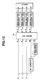
- Figure 12 shows a block diagram of another image processing apparatus having the function of suppressing the white component expressed by the equations (4).
- the image processing apparatus comprises a minimum value detector 11, a non-linear converter 12, pseud halftone processor 14-1 - 14-4 and a display 15, which are similar to those shown in Figure 1 and Figure 11.
- a matrix unit 16 is provided instead of the subtractors 13-1 - 13-3 shown in Figure 1 and Figure 11.
- the minimum value detector 11 detects a minimum value among the R,G,B colour data and outputs the detected minimum value as WO data.
- the non-linear converter 12 performs the non-linear conversion on the inputted WO data in accordance with the non-linear characteristic f(W) shown in Figure 10 (B) and outputs the W1 data.
- the WO data and W1 data are supplied to the matrix unit 16 together with the R,G,B colour data.
- the matrix unit 16 performs a matrix operation expressed by the equation (5) on the R,G,B colour data and the WO,W1 data to obtain the R′,G′,B′,W′ data for displaying a colour image.
- the W′ data representing the white component can be obtained in consideration with not only the white component (WO,W1) but also the R,G,B colour data.
- the colour can be displayed suitably.
- the colour displayed on the basis of the R,G,B colour data can be modified. Therefore, by substituting appropriate values for these fifteen parameters, the colour to be displayed on the basis of the R,G,B colour data can be suitable.
- the R′,G′,B′,W′ data from the matrix unit 16 are subjected to the pseud halftone process by the pseud halftone processors 14-1 - 14-4, respectively, to form binary driving data, i.e. R ⁇ , G ⁇ , B ⁇ , W ⁇ data which drive the liquid crystal cells provided with the R,G,B,W filters.
- the R ⁇ ,G ⁇ ,B ⁇ ,W ⁇ data are supplied to the display 15.
- the white component is suppressed by using the suitable conversion characteristic, so the white pixels can be definitely prevented from dotting in the image having low brightness.
- colour correction for example, the correction of the difference between the colour defined by the R,G,B colour data and the colour actually displayed on the basis of the R,G,B colour data can be carried out as well as the suppressing of the white pixels. Accordingly, the colour displayed can be more suitable.
- the colour conversion or the colour adjustment can be carried out by changing the matrix parameters.
- the pseud halftone processors 14-1 - 14-4 are provided corresponding to the R,G,B,W colours, respectively, and the pseud halftone process, such as an error diffusion method, is performed on each colour.
- the display is composed of liquid crystal cells each of which displays a binary image.
- a display device which is composed of liquid crystal cells or other display elements each of which can display an image having more than two multi-levels may be used.
- a multi-level pseud halftone process may be adopted as the pseud halftone process.
- liquid crystal display such as a cathode-ray tube or a light-emitting diode display, may be used instead of the liquid crystal display disclosed in the embodiments.
- RGB red, green, blue
- L*a*b* yellow, yellow, magenta, cyan
- YIQ yellow, magenta, cyan
- YIQ yellow, magenta, cyan
- Such colour data may be supplied from an image scanner which can read a colour image, a colour video camera or a still video camera as well as the host computer.
- the "number" or "rate” of pixels corresponds to the ratio of activated pixels in a unit area, these activated pixels being transparent liquid crystal cells in the case of a ferroelectric liquid crystal display.
Abstract
Description
- This invention relates to an image processing apparatus which processes data for a colour image so as to display the colour image by a display device, such as a liquid crystal display.
- Recently, liquid crystal displays have been used as display devices of personal computers, word processors or televisions.
- The use of a bistable liquid crystal element has been proposed by Clark and Lagerwall (U.S. Patent 4,367,924). Ferroelectric liquid crystal having Chiral smectic C phase (Sm C *) or H phase (Sm H *) is usually used as the bistable liquid crystal. This liquid crystal has bistable states in an electric field, including a first optically stable state (first orientation state) and a second optically stable state (second orientation state). Accordingly, unlike an optical modulation element used in a TN (twist nematic) type liquid crystal, the liquid crystal is oriented in the first optically stable state for one electric field vector, and the liquid crystal is oriented in the second optically stable state for the other electric field vector.
- The liquid crystal of this type quickly responds to the applied electric field to assume one of the two stable states and maintains the state when the electric field is removed.
- However, the bistable liquid crystal element has only two states, so a liquid crystal display which consists of such bistable liquid crystal cells cannot display a halftone image or a full colour image.
- The present invention has been made in the light of the above problems and its object is to provide an image processing apparatus and method which can display a colour image with rich colours.
- The present invention also provides an image processing apparatus and method which can display a full colour image by using a display device, of which each display element displays an image with at least two levels.
- The present invention also provides an image processing apparatus and method which can display a colour image having low brightness without the deterioration of the image quality.
- According to a first aspect of the present invention, there is provided an image processing apparatus, comprising extraction means for extracting white component data from colour data representing a colour image; generating means for generating colour display data on the basis of the colour data and the white component data, the colour display data including white display data; and display means for displaying a colour image in accordance with the colours display data, said display means displaying white pixels in accordance with the white display data.
- According to a second aspect of the present invention, there is provided an image processing apparatus comprising extracting means for extracting white component data from colour data representing a colour image; suppressing means for suppressing the white component data; generating means for generating colour display data on the basis of the colour data and the suppressed white component data; and display means for displaying a colour image in accordance with the colour display data.
- According to a third aspect of the present invention, there is provided an image processing apparatus, comprising: input means for inputting multi-level colour data representing a colour image; pseud halftone processing means for performing on the multi-level colour data a pseud halftone process to express a halftone image by controlling the rate of pixels in a unit area, and display means for displaying a colour image in accordance with the colour data subjected to the pseud halftone process.
- According to a fourth aspect of the present invention, there is provided an image processing apparatus, comprising: input means for inputting colour data representing a colour image; processing means for processing the colour data to produce colour display data; and display means for displaying a colour image on the basis of the colour display data; characterised in that said display means displays the colour image using a plurality of two level pixels, and that said processing means produces the colour display data which expresses halftone images using the plurality of two level pixels.
- According to further aspects of the present invention, there are provided methods of image processing which are carried out by apparatus in accordance with the first, second, third and fourth aspects of the present invention.
- The aforesaid objectives and effects and other objectives and effects of the present invention are evident from the following examples of preferred embodiments in accordance with the invention.
-
- Figure 1 is a block diagram of an image processing apparatus in accordance with an embodiment of the present invention;
- Figure 2 is a drawing to show a part of a liquid crystal display panel;
- Figure 3 is a table to show sixteen colours which can be displayed by a basic unit in accordance with an embodiment of the invention;
- Figure 4 is a drawing to show the process of extracting W data;
- Figure 5 is a block diagram of a pseud halftone processor;
- Figure 6 is a drawing to show an example of weight coefficients;
- Figure 7 is a block diagram of a display;
- Figure 8 is a drawing to show the operation of a ferroelectric liquid crystal;
- Figure 9 is a drawing to show the states of a ferroelectric liquid crystal;
- Figures 10A, B and C illustrate the process of generating R′, G′, B′,W′ data;
- Figure 11 is a block diagram of another image processing apparatus in accordance with a second embodiment of the present invention; and
- Figure 12 is a block diagram of another image processing apparatus in accordance with a further embodiment of the present invention.
- Figure 1 shows a block diagram of an image processing apparatus embodying the present invention. The image processing apparatus comprises a minimum value detector 11, subtractors 13-1 - 13-3, pseud halftone processors 14-1 - 14-4 and a
display 15. Red (R), Green (G) and Blue (B) colour data representing a colour image are inputted from an external device, such as a host computer, pixel by pixel. - The
display 15 has a liquid crystal display panel which is composed of ferroelectric liquid crystal. On the liquid crystal display panel, 640 x 560 liquid crystal cells, each of which can assume two states, i.e. a transparent state and an opaque state, are arranged in a matrix basis. - Figure 2 shows a part of the liquid
crystal display panel 50. Abasic unit 51 forms a pixel and consists of four liquid crystal cells, each state of which can be independently controlled. Namely, the four liquid crystal cells can transmit or shut off the light from the back of the liquidcrystal display panel 50, respectively. - Four colour filters, red (R), green (G), blue (B) and white (W) filters, are provided on the four liquid crystal cells in the
basic unit 51. Therefore, thebasic unit 51 can display sixteen colours shown in Figure 3 by controlling the states of the four liquid crystal cells, independently. - In Figure 3, "1" represents a transparent state and "O" represents an opaque state. Thus, the liquid
crystal display panel 50 is provided with not only R,G,B filters but also W filters. Accordingly, it can display extra eight colours, such as light grey, light blue and so on, which cannot be displayed by using only R,G,B filters. - On the liquid
crystal display panel 50, twenty sets ofbasic unit 51 are arranged in one square millimetre. A colour displayed by each of such a smallbasic unit 51 cannot be recognised by human visual characteristics. Therefore, a colour composed of mixtures of colours of neighbouring dozens of pixels (basic units) can be recognised. - Accordingly, if a pseud halftone process, which expresses a halftone image by controlling the rate of pixels to be displayed in a unit area, is performed on R,G,B colour data, a full colour image can be displayed by the liquid
crystal display panel 50, of which each liquid crystal cell displays binary image and each basic unit displays sixteen colours. - The minimum value detector 11 detects a minimum value among the 8-bit R,G,B colour data supplied from a host computer via a data bus, pixel by pixel. The minimum value detected by the minimum value detector 11 is treated as W data which represents a white component.
- The process of extracting the W data from the R,G,B colour data will be described with reference to Figure 4.
- In Figure 4, when all the R,G,B colour data is 255 i.e. 8-bits, a white image is represented by the R,G,B colour data. Therefore, a minimum value among the R,G,B colour data Min (R,G,B) corresponds to a white component value.
- Accordingly, if the Min (R,G,B) is assumed as the W data, R′,G′,B′ data, which are used for driving the liquid
crystal display panel 50, can be formed by removing the W component from R,G,B components, respectively, as expressed by equations (1).
- The subtractors 13-1 - 13-3 subtract the W data, which obtained by the minimum value detector 11, from the R,G,B colour data, respectively, so as to generate the R′,G′,B′ data expressed in equations (1).
- The R′,G′,B′ data are multi-value data, so they cannot be directly used for driving the liquid
crystal display panel 50, of which liquid crystal cells assume two states. - Therefore, the pseud halftone processors 14-1 - 14-4 perform the pseud halftone processes on the R′,G′,B′,W data, respectively, so as to convert them into binary driving data, i.e. R˝,G˝,B˝,W˝ data which correspond to the liquid crystal cells provided with the R,G,B,W filters.
- The pseud halftone processors 14-1 - 14-3 may perform the pseud halftone process, which expresses a halftone image by controlling the rate of pixels to be displayed in a unit area, in accordance with an error diffusion method, an ordered dither process and so on. Details of such methods are disclosed in U.S. Patent 4,958,218 and IEEE Transactions on Communications, Vol. Com-29, No.12, December 1981, pages 1898-1925 which are incorporated herein by reference.
- Figure 5 is a block diagram of the pseud halftone processor 14-1. In Figure 5, the R′ data is processed in accordance with the error diffusion method and the R′ data is assumed as image data Xij.
- In the error diffusion method, image data Xij is added by an
adder 81 to a value which is obtained by multiplying a weight coefficient α ij designated by aweighting circuit 82 to an error εij (the difference between correction data X′ij which has previously been generated and output data Yij) stored in anerror buffer memory 83. The adding process can be expressed by the following equation:
- Figure 6 shows an example of weight coefficients. In Figure 6, * indicates a position of a pixel which is at present being processed.
- Next, the correction data X′ij is compared with the threshold value T (in this case, D max = 255, T = 127) by a
binarising circuit 84, so that data Yij is output. Yij is the data which was binarised into 1s or 0s. The binarised data is stored into anoutput buffer 87 and supplied to thedisplay 15. - On the other hand, the difference εij between the correction data X′ij and the data Y′ij, which is obtained by multiplying the data Yij output from the
binarising circuit 84 by 255, is calculated by acalculator 85. The result from thecalculator 85 is stored into an area at a position corresponding to apixel position 86 in theerror buffer memory 83. - By repeating those operations, the binarisation due to the error diffusion method is executed.
- The pseud halftone processors 14-2 - 14-3 can be realised by the same construction as that of the pseud halftone processor 14-1 shown in Figure 5.
- The R˝,G˝,B˝,W˝ binary data obtained by the binarising process of the pseud halftone processors 14-1 - 14-4 are supplied to the
display 15. - Figure 7 shows the construction of the
display 15. Line memories 41-1 - 41-4 store the R˝,G˝,B˝,W˝ binary data obtained by the pseud halftone process. Amultiplexer 42 rearranges the R˝,G˝,B˝,W˝ binary data pixel by pixel, so as to arrange them in a data arrangement corresponding to that of the R,G,B,W filters shown in Figure 2. Aframe memory 43 stores a frame of the R˝,G˝,B˝,W˝ binary data subjected to the rearrangement by themultiplexer 42. - A
display controller 44 reads out the R˝,G˝,B˝,W˝ binary data from theframe memory 43, line by line, and supplies them to ashift register 45 in a serial manner. - The
display controller 44 also supplies control signals to aline memory 46, adriver 47 and adecoder 48. - The
shift register 45 supplies a line of the R˝,G˝,B˝,W˝ binary data to theline memory 46 in parallel manner. Theline memory 46 supplies the R˝,G˝,B˝,W˝ binary data to thedriver 47 as binary signals indicating ON/OFF states of a line of the liquid crystal cells. Thedriver 47 drives each of the liquid crystal cells of the liquidcrystal display panel 50 in response to the R˝,G˝,B˝,W˝ binary data from theline memory 46. - The
decoder 48 indicates a line to be driven. Adriver 49 sequentially drives the liquid crystal cells of the liquidcrystal display panel 50, line by line. - According to the above construction, each of 640x560 liquid crystal cells on the liquid
crystal display panel 50 assumes either the transparent state or the opaque state in response to the R˝,G˝,B˝,W˝ data. Thereby, a full colour image represented by the R,G,B colour data is displayed on the liquidcrystal display panel 50. - As explained above, the white component is extracted from the input R,G,B colour data, and full colour image display data, i.e. Red, Green, Blue and White display data, are formed on the basis of the extracted white component. Then a full colour image is displayed by the liquid crystal display panel, on which white filters are provided in addition to red, green, blue filters, in accordance with the Red, Green, Blue and White display data.
- According to this embodiment, a full colour image can be displayed with rich colours by using the liquid crystal display panel, each liquid crystal cell of which displays binary image.
- Besides, the pseud halftone process, such as an error diffusion method or an ordered dither process, is performed on the multi-level data representing a colour image, so as to obtain binary colour image data subjected to the pseud halftone process.
- According to this embodiment, a full colour image can be displayed by using the liquid crystal display panel, each liquid crystal cell of which assumes two states.
- It will be appreciated that the combination of the pseud halftone process and the display may be used without the white filters.
- The liquid
crystal display panel 50 will now be described in detail. - Chiral smectic liquid crystal having ferroelectric property is particularly suitable as a liquid crystal material used for the liquid
crystal display panel 50. Specifically, chiral smectic C phase (SmC*), chiral smectic G phase (Sm G*), chiral smectic F phase (Sm F*), chiral smectic I phase (Sm I*) or chiral smectic H phase (Sm H*) liquid crystal may be used. Details of the ferroelectric liquid crystal are described in "Ferroelectric Liquid Crystals" Le Journal de Physique Letters 1975, No. 36 (L-69), "Submicro Second Bistable Electro-optic Switching in Liquid Crystals" Applied Physics Letters, 1980, No. 36 (11), and "Liquid Crystals" Solid-State Physics of Japan, 1981, No. 16 (141). - Specific examples of the ferroelectric liquid crystal compound are decyloxybenzylidene -p′-amino-2-methylbutylcinnamate (DABAMBC), hexyloxybenzylidene-p′-amino-2-chloropropyl cinnamate (HOBACPC), and 4-0-(2-methyl) - butylresorcylidene -4′- octylaniline (MBRA 8).
- The ferroelectric liquid crystal which exhibits cholesteric phase at a temperature higher than that of chiral smectic phase liquid crystal is most preferable. For example, biphenylester liquid crystal which exhibits a phase transistion temperature.
- When the element is constructed by using one of those materials, the element may be supported by a copper block having a heater embedded therein in order to keep the element at a temperature at which the liquid crytal compound exhibits a desired phase.
- Figure 8 shows a cell to explain the operation of the ferroelectric liquid crystal. The Sm C* phase is assumed as the desired phase.
-
Numerals crystal molecule layer 32 is normal to the glass plate is filled therebetween.Thick lines 33 represent the liquid crystal molecules which form a continuous spiral structure in parallel with the substrate plane. An angle between acentre axis 35 of the spiral structure and an axis of theliquid crystal molecules 33 is represented by H. Theliquid crystal molecules 33 each has a bipolar moment (P⊥) 34 orthogonally to the molecule. - When a voltage higher than a predetermined threshold is applied between the
substrates liquid crystal molecules 33 is released and theliquid crystal molecules 33 may be reoriented so that all the bipolar moments (P⊥) 34 are oriented along the electric field. Theliquid crystal molecule 33 is of elongated shape and a refractive index along a major axis and a refractive index along a minor axis are different. Thus, when polarisers which are cross-nicol to each other are placed on the opposite sides of the glass plate, a liquid crystal optical element whose optical characteristic changes depending on a polarity of applied voltage is provided. - The above mentioned liquid crystal cell may be very thin (for example, 10 µm or less). As the liquid crystal layer is thinned, the spiral structure of the liquid crystal molecules is released even under non-aplication of the electric field as shown in Figure 9, and the bipolar moment P or P′ is oriented either upward (64) or downward (64′). One half of an angle between the molecule axis of the
liquid crystal molecule 63 and adirection 63′ is called a tilt angle (H) which is equal to one half of an apex angle of a cone of the spiral structure. - Electric fields E or E′ of different polarity, which are higher than a predetermined threshold, are applied to such a cell by voltage application means 61 or 61′ as shown in Figure 9. Thus, the bipolar moment is reoriented upward 64 or downward 64′ in accordance with the electric field vector of the electric field E or E′, and the liquid crystal molecules are oriented in either the first
stable state 63 or the secondstable state 63′ - There are two advantages in utilising the ferroelectricity as the liquid crystal optical element, as described above.
- First, the response speed is very fast, and secondly, the orientation of the liquid crystal molecule is bistable. The second advantage is explained with reference to Figure 9.
- When the electric field E is applied, the liquid crystal molecule is oriented in the first
stable state 63 which is stable even after the electric field is removed. When the electric field E′ of the opposite polarity is applied, the liquid crystal molecule is oriented in the secondstable state 63′ which is also stable even after the electric field is removed. - The cell is preferably as thin as possible in order to effectively attain the fast response speed and the bistability.
- As explained above, according to the construction as shown in Figure 1, a colour image is displayed by using the liquid
crystal display panel 50, on which white filters are provided in addition to red, green, blue filters. Accordingly, it is possible to display a full colour image with rich colours. - However, when pixels having high brightness, such as white pixels, are sparsely dotted within dozens of pixels representing the same colour, such pixels are prominent as differential granules and lower the quality of the displayed image.
- For example, colours of low brightness, such as dark grey, dark red, dark green or dark blue, etc., contain a little white component. So the liquid crystal cells provided with white filters sparsely become ON state. Consequently, white pixels sparsely dot in the displayed image and the quality of the displayed image may lower.
- However, the white component can be expressed by the combination of liquid crystal cells of low brightness which are provided with R,G,B filters, instead of liquid crystal cells of high brightness which are provided with W filters.
- Accordingly, when the colour of low brightness, such as dark grey or dark red etc., in which white pixels may sparsely dot if the process expressed by the equation (1) is performed, is displayed, such colour should be displayed by the combination of liquid crystal cells which are provided with R,G,B filters without using liquid crystal cells which are provided with W filters. Thereby, white pixels do not dot in the displayed image and the deterioration of the image quality can be prevented.
- Alternatively, it is not necessary to prevent the occurrence of the white pixels, when the colour of high brightness, of which the quality does not lower even if the process expressed by equations (1) is performed, is displayed. Accordingly, the colour of high brightness should be displayed by using liquid crystal cells which are provided with not only R,G,B filters but also W filters. Thus, a full colour image can be displayed with rich colours.
- In view of these circumstance, the W data, which is represented by the minimum value among the R,G,B colour data, is converted in accordance with a predetermined conversion characteristic. This conversion characteristic suppresses white component at the range where the amount of white component is relatively low. Then, the white component which is suppressed by this conversion is compensated by increasing the amount of R,G,B components.
- The process for generating R′,G′,B′,W′ data from the R,G,B colour data by using a non-linear characteristic will now be explained with reference to Figure 10.
- In Figure 10(A), a minimum value among the R,G,B colour data (Min (R,G,B)) corresponds to a white component value.
- Then, the W data representing the white component value (Min (R,G,B)) is converted into W′ data in accordance with the non-linear characteristic f(W) shown in Figure 10(B). The R′,B′,G′ data are formed by subtracting the W′ data representing white component subjected to the non-linear conversion from the R,G,B colour data, respectively, as expressed by equations (2).

wherein α is a non-linear conversion parameter, with a suitable value being approximately 2.5. - According to the process expressed by the equations (2), the amount of the white component represented by the W′ data decreases, in comparison with that represented by the W data, which is not subjected to the non-linear conversion. Then, the amount of each of the R,G,B components increases in response to the decrease of the white component.
- For example, in Figure 10(B), whenrepresents the white component which is not subjected to the non-linear conversion, the white component is suppressed from
 to
to in accordance with the above non-linear conversion. The decrease of the white component (
 -
- ) is added to the R,G,B components, respectively, so as to compensate the fall in the brightness of the image to be displayed.
- Figure 11 shows a block diagram of an image processing apparatus having the function of suppressing the white component expressed by the equations (2).
- The image processing apparatus comprises a minimum value detector 11, a
non-linear converter 12, subtractors 13-1 - 13-3, pseud halftone processors 14-1 - 14-4 and adisplay 15. The construction is the same as that shown in Figure 1 except thenon-linear converter 12. - The minimum value detector 11 detects a minimum value among the 8-bit R,G,B colour data and outputs the detected minimum value as W data.
- The
non-linear converter 12 performs the non-linear conversion on the inputted W data in accordance with the non-linear characteristic f(W) shown in Figure 11 (B). Namely, the W data is subjected to the non-linear conversion which suppresses the white component at the range where the amount of the white component is relatively low. - In this embodiment, the non-linear conversion is performed by using a look-up table stored in ROM or RAM which is included in the
non-linear converter 12. - Subtractors 13-1 - 13-3 subtract the W′ data obtained by the
non-linear converter 12 from the R,G,B colour data, respectively, so as to form the R′,G′,B′ data expressed by the equations (2). - Thus formed R′,G′,B′,W′ data are subjected to the pseud halftone process by the pseud halftone processors 14-1 - 14-4, respectively, to obtain binary driving data, i.e. R˝,G˝,B˝,W˝ data which drive the liquid crystal cells provided with the R,G,B,W filters. The R˝,G˝,B˝,W˝ data are supplied to the
display 15. - As explained above, the white component, which is extracted from the R,G,B colour data for displaying the white pixels, is subjected to the non-linear conversion, so as to suppress the white pixels to be displayed by using the liquid crystal cells on which the W filters are provided.
- Accordingly, in the case where a colour image having low brightness is displayed, the white pixels do not sparsely dot and the deterioration of the image quality can be prevented.
- Moreover, a colour image having high brightness is displayed by using the liquid crystal cells on which not only the R,G,B filters but also the W filter are provided, so it can be displayed with rich colours.
- On the other hand, various conversion characteristics other than the non-linear characteristic shown in Figure 10(B) may be adopted to suppress the white pixels which are displayed by the liquid crystal cells having the W filters, when the colour having low brightness is displayed.
- For example, a conversion characteristic shown in Figure 10(C) may be adopted. This conversion is expressed by the following equations (3)

- According to the conversion expressed by the equations (3), when the white component value is equal to or less than a predetermined value C, the white component value is changed into "0", so as to display the colour having low brightness without using the liquid crystal cells having the W filters.
- When the white component value is more than the predetermined value C, the colour is displayed by using the liquid crystal cells having the W filters in accordance with the amount of the white component.
- Needless to say, the predetermined value C may be set for a suitable value in consideration of the display characteristic of the liquid crystal display panel and so on.
- In the image processing apparatus shown in Figure 10, the decrease of the white component due to the non-linear conversion is added to the R,G,B components, so as to compensate for the fall in the brightness of the image to be displayed. However, it is possible that the fall in the brightness cannot be compensated by means of the above simple algorithm because the light transparent characteristics of the liquid crystal cells and the colour filter thereon are not constant.
- Moreover, the non-linear characteristic to obtain the W′ data expressed by the equations (2) can be merely modified by the changing the non-linear conversion parameter α. Therefore, the modification of the non-linear characteristic cannot be changed freely, as it is difficult to adjust the conversion characteristic to the characteristics of the display and the input colour data.
- In view of these circumstances, the W′ data is obtained by the arithmetic operation dependant on the value W0 which is a minimum value among the R,G,B colour data and the value W1 which is obtained by non-linear converting the minimum value W0. Namely, the W′ data is obtained by using the equations (4).
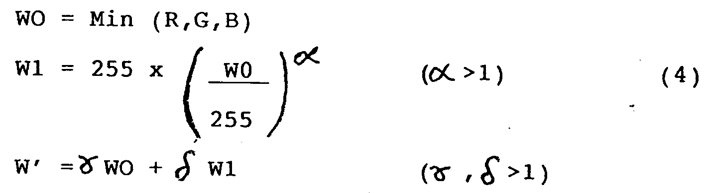
- According to the non-linear conversion expressed by the equations (4), the non-linear conversion characteristic can approximate to the optimum conversion characteristic easily and the quality of the displayed image can be improved.
- Figure 12 shows a block diagram of another image processing apparatus having the function of suppressing the white component expressed by the equations (4).
- The image processing apparatus comprises a minimum value detector 11, a
non-linear converter 12, pseud halftone processor 14-1 - 14-4 and adisplay 15, which are similar to those shown in Figure 1 and Figure 11. - In Figure 12, a
matrix unit 16 is provided instead of the subtractors 13-1 - 13-3 shown in Figure 1 and Figure 11. - The minimum value detector 11 detects a minimum value among the R,G,B colour data and outputs the detected minimum value as WO data.
- The
non-linear converter 12 performs the non-linear conversion on the inputted WO data in accordance with the non-linear characteristic f(W) shown in Figure 10 (B) and outputs the W1 data. - The WO data and W1 data are supplied to the
matrix unit 16 together with the R,G,B colour data. - The
matrix unit 16 performs a matrix operation expressed by the equation (5) on the R,G,B colour data and the WO,W1 data to obtain the R′,G′,B′,W′ data for displaying a colour image.
- If "0" is substituted for the matrix parameters a41, a42, a43, and "" and "
 " are substituted for the matrix parameters a44 and a45, respectively, the arithmetic operation expressed by the equations (4) can be carried out.
- Alternatively, if the appropriate values are substituted for the matrix parameters a41, a42, a43, a44, a45, the W′ data representing the white component can be obtained in consideration with not only the white component (WO,W1) but also the R,G,B colour data.
- Namely, if those parameters are set in view of the characteristics in colour or brightness of the display, the colour can be displayed suitably.
- Moreover, by altering the values of the matrix parameters a11 - a35 which are used for obtaining the R′,G′,B′ data, the colour displayed on the basis of the R,G,B colour data can be modified. Therefore, by substituting appropriate values for these fifteen parameters, the colour to be displayed on the basis of the R,G,B colour data can be suitable.
- The R′,G′,B′,W′ data from the
matrix unit 16 are subjected to the pseud halftone process by the pseud halftone processors 14-1 - 14-4, respectively, to form binary driving data, i.e. R˝, G˝, B˝, W˝ data which drive the liquid crystal cells provided with the R,G,B,W filters. The R˝,G˝,B˝,W˝ data are supplied to thedisplay 15. - As explained above, the white component is suppressed by using the suitable conversion characteristic, so the white pixels can be definitely prevented from dotting in the image having low brightness.
- Moreover, the matrix operation is used, so colour correction, for example, the correction of the difference between the colour defined by the R,G,B colour data and the colour actually displayed on the basis of the R,G,B colour data can be carried out as well as the suppressing of the white pixels. Accordingly, the colour displayed can be more suitable.
- Alternatively, if the matrix parameters are changeable, the colour conversion or the colour adjustment can be carried out by changing the matrix parameters.
- In the embodiments described above, the pseud halftone processors 14-1 - 14-4 are provided corresponding to the R,G,B,W colours, respectively, and the pseud halftone process, such as an error diffusion method, is performed on each colour.
- Alternatively, another process, which quantises the four-dimension space defined by the R,G,B,W data, to convert it into one of the sixteen states shown in Figure 6 and diffuses the error generated by the quantisation into pixels to be processed later, may be adopted as the pseud halftone process.
- In the embodiments,the display is composed of liquid crystal cells each of which displays a binary image. However, a display device, which is composed of liquid crystal cells or other display elements each of which can display an image having more than two multi-levels may be used. In this case, a multi-level pseud halftone process may be adopted as the pseud halftone process.
- Moreover, other types of display devices, such as a cathode-ray tube or a light-emitting diode display, may be used instead of the liquid crystal display disclosed in the embodiments.
- Instead of the R,G,B colour space signals, other colour space signals, such as YMC (yellow, magenta, cyan), L*a*b*, YIQ, may be easily adopted as colour data representing a colour image to be displayed.
- Such colour data may be supplied from an image scanner which can read a colour image, a colour video camera or a still video camera as well as the host computer.
- It will be appreciated that the combination of pseud halftone processors and display may be used without the white filters.
- It will be appreciated that in pseud halftone processing the "number" or "rate" of pixels corresponds to the ratio of activated pixels in a unit area, these activated pixels being transparent liquid crystal cells in the case of a ferroelectric liquid crystal display.
- The present invention was explained above in reference to a few preferred embodiments, but needless to say, the present invention is not limited to these embodiments but various modifications and changes are possible.
Claims (51)
- Image processing apparatus, comprising:
extraction means for extracting white component data from colour data representing a colour image;
generating means for generating colour display data on the basis of the colour data and the white component data, the colour display data including white display data; and
display means for displaying a colour image in accordance with the colour display data, said display means displaying white pixels in accordance with the white display data. - Apparatus according to claim 1, wherein said display means further displays red, green and blue pixels.
- Apparatus according to claim 1, wherein said display means has a liquid crystal display panel which is composed of a plurality of liquid crystal cells.
- Apparatus according to claim 3, wherein said liquid crystal display panel is composed of ferroelectric liquid crystal.
- Apparatus according to claim 1, wherein said extraction means extracts a minimum value among the colour data as the white component data.
- Apparatus according to claim 5, wherein said extraction means detects a minimum value among red, green and blue data included in the colour data.
- Apparatus according to claim 1, wherein said generating means generates the colour display data by removing the white component data from the colour data.
- Apparatus according to claim 7, wherein said generating means subtracts the white component data from red, green and blue data included in the colour data.
- Image processing apparatus, comprising:
extraction means for extracting white component data from colour data representing a colour image;
suppressing means for suppressing the white component data;
generating means for generating colour display data on the basis of the colour data and the suppressed white component data; and
display means for displaying a colour image in accordance with the colour display data. - Apparatus according to claim 9, wherein said display means displays white pixels in accordance with the colour display data.
- Apparatus according to claim 10, wherein said display means further displays red, green and blue pixels.
- Apparatus according to claim 9, wherein said display means has a liquid crystal display panel which is composed of a plurality of liquid crystal cells.
- Apparatus according to claim 12, wherein said liquid crystal display panel is composed of ferroelectric liquid crystal.
- Apparatus according to claim 9, wherein said suppressing means suppresses the white component data in accordance with a non-linear characteristic.
- Apparatus according to claim 9, wherein said extracting means extracts a minimum value among the colour data as the white component data.
- Apparatus according to claim 15, wherein said extraction means extracts a minimum value among red, green and blue data included in the colour data.
- Apparatus according to claim 9, wherein said generating means generates the colour display data by removing the suppressed white component data from the colour data.
- Apparatus according to claim 17, wherein said generating means subtracts the suppressed white component data from red, green and blue data included in the colour data.
- Image processing apparatus, comprising:
input means for inputting multi-level colour data representing a colour image;
pseud halftone processing means for performing on the multi-level colour data a pseud halftone process to express a halftone image by controlling the rate of pixels in a unit area; and
display means for displaying a colour image in accordance with the colour data subjected to the pseud halftone process. - Apparatus according to claim 19, wherein said display means is composed of a plurality of display elements, each of which displays binary image.
- Apparatus according to claim 19, wherein said display means has a liquid crystal display panel which consists of a plurality of liquid crystal cells.
- Apparatus according to claim 21, wherein each of said liquid crystal cells displays binary image.
- Apparatus according to claim 21, wherein said liquid crystal display panel is composed of ferroelectric liquid crystal.
- Apparatus according to claim 19, wherein said pseud halftone processing means performs the pseud halftone process in accordance with an error diffusion method.
- Apparatus according to claim 19, wherein the multi-level colour data includes white display data, and said di.splay means displays white pixels in accordance with the white display data subjected to the pseud halftone process.
- Image processing method, comprising:
extracting white component data from colour data representing a colour image;
generating colour display data on the basis of the colour data and the white component data, the colour display data including white display data; and
displaying a colour image in accordance with the colour display data, the colour image comprising white pixel in accordance with the white display data. - Method according to claim 26, wherein the colour image is displayed by using red, green, blue and white pixels.
- Method according to claim 26, wherein the colour image is displayed by a liquid crystal display panel which is composed of a plurality of liquid crystal cells.
- Method according to claim 28, wherein the liquid crystal di.splay panel is composed of ferroelectric liquid crystal.
- Method according to claim 26, wherein a minimum value among the colour data is extracted as the white component data.
- Method according to claim 30, wherein the minimum value among red; green and blue data included in the colour data is extracted as the white component data.
- Method according to claim 26, wherein the colour display data are generated by removing the white component data from the colour data.
- Method according to claim 32, wherein the colour display data are generated by subtracting the white component data from red, green and blue data included in the colour data.
- Image processing method, comprising:
extracting white component data from colour data representing a colour image;
suppressing the white component data;
generating colour display data on the basis of the colour data and the suppressed white component data; and
displaying a colour image in accordance with the colour display data. - Method according to claim 34, wherein the colour image is displayed by using red, green, blue and white pixels.
- Method according to claim 34, wherein the colour image is displayed by a liquid crystal display panel which is composed of a plurality of liquid crystal cells.
- Method according to claim 36, wherein the liquid crystal display panel is composed of ferroelectric liquid crystal.
- Method according to claim 34, wherein the white component is suppressed in accordance with a non-linear characteristic.
- Method according to claim 34, wherein a minimum value among the colour data is extracted as the white component data.
- Method according to claim 39, wherein the minimum value among red, green and blue data included in the colour data is extracted as the white component data.
- Method according to claim 34, wherein the colour display data are generated by removing the suppressed white component data from the colour data.
- Method according to claim 41, wherein the colour display data are generated by subtracting the suppressed white component data from red, green and blue data included in the colour data.
- Image processing method, comprising:
inputting multi-level colour data representing a colour image;
performing on the multi-level colour data a pseud halftone process to express a halftone image by controlling the rate of pixels in a unit area; and
displaying a colour image in accordance with the colour data subjected to the pseud halftone process. - Method according to claim 42, wherein the colour image is displayed by a plurality of display elements, each of which displays a binary image.
- Method according to claim 43, wherein the colour image is displayed by a liquid crystal display panel which is composed of a plurality of liquid crystal cells.
- Method according to claim 45, wherein each of said liquid crystal cells displays a binary image.
- Method according to claim 45, wherein said liquid crystal display panel is composed of ferroelectric liquid crystal.
- Method according to claim 43, wherein the pseud halftone process is performed in accordance with an error diffusion method.
- Image processing apparatus, comprising:
input means for inputting colour data representing a colour image;
processing means for processing the colour data to produce colour display data; and
display means for displaying a colour image on the basis of the colour display data;
characterised in that said display means displays the colour image using a plurality of two level pixels,
and that said processing means produces the colour display data which expresses halftone images by using the plurality of two level pixels. - Apparatus according to claim 49, wherein said processing means comprises:
extraction means for extracting white component data from the colour data; and
generating means for generating colour display data on the basis of the colour data and the white component data, the colour display data including white display data,
and said display means displays white pixels in accordance with the white display data. - Apparatus according to claim 49, wherein said processing means comprises:
pseud halftone processing means for performin on the colour data a pseud halftone process to express a halftone image by controlling the number of pixels in a unit area.
Applications Claiming Priority (2)
| Application Number | Priority Date | Filing Date | Title |
|---|---|---|---|
| JP291453/91 | 1991-11-07 | ||
| JP29145391 | 1991-11-07 |
Publications (3)
| Publication Number | Publication Date |
|---|---|
| EP0541295A2 true EP0541295A2 (en) | 1993-05-12 |
| EP0541295A3 EP0541295A3 (en) | 1994-07-06 |
| EP0541295B1 EP0541295B1 (en) | 1998-08-19 |
Family
ID=17769065
Family Applications (1)
| Application Number | Title | Priority Date | Filing Date |
|---|---|---|---|
| EP92309931A Expired - Lifetime EP0541295B1 (en) | 1991-11-07 | 1992-10-29 | Image processing apparatus |
Country Status (5)
| Country | Link |
|---|---|
| US (1) | US5929843A (en) |
| EP (1) | EP0541295B1 (en) |
| JP (1) | JPH05241551A (en) |
| CA (1) | CA2081643C (en) |
| DE (1) | DE69226689T2 (en) |
Cited By (19)
| Publication number | Priority date | Publication date | Assignee | Title |
|---|---|---|---|---|
| EP0673161A3 (en) * | 1994-03-15 | 1996-04-03 | Canon Kk | Video information display system and display apparatus applicable to the same. |
| EP0700215A3 (en) * | 1994-08-04 | 1996-06-19 | Sony Corp | Plane sequential color display apparatus and method for driving same |
| WO2001037251A1 (en) * | 1999-11-12 | 2001-05-25 | Koninklijke Philips Electronics N.V. | Liquid crystal display device witr high brightness |
| WO2001037249A2 (en) * | 1999-11-12 | 2001-05-25 | Koninklijke Philips Electronics N.V. | Liquid crystal display apparatus with improved luminance control |
| EP1104923A2 (en) * | 1999-11-06 | 2001-06-06 | Samsung Electronics Co., Ltd. | Colour sequential light valve display device |
| WO2005091263A1 (en) * | 2004-03-19 | 2005-09-29 | Koninklijke Philips Electronics N.V. | Active matrix display with pixel to pixel non-uniformity improvement at low luminance level |
| WO2006035246A1 (en) * | 2004-09-30 | 2006-04-06 | Cambridge Display Technology Limited | Multi-line addressing methods and apparatus |
| EP1748405A3 (en) * | 2005-07-29 | 2007-06-06 | Samsung Electronics Co., Ltd. | Video signal processor, display device, and method of driving the same |
| EP1947632A3 (en) * | 2003-05-07 | 2010-02-17 | Samsung Electronics Co., Ltd. | Four-color data processing system |
| US7821065B2 (en) | 1999-03-02 | 2010-10-26 | Semiconductor Energy Laboratory Co., Ltd. | Semiconductor device comprising a thin film transistor comprising a semiconductor thin film and method of manufacturing the same |
| US7851797B2 (en) * | 1999-12-14 | 2010-12-14 | Semiconductor Energy Laboratory Co., Ltd. | Display device including a color filter or color filters over a pixel portion and a driving circuit for driving the pixel portion |
| US7944410B2 (en) | 2004-09-30 | 2011-05-17 | Cambridge Display Technology Limited | Multi-line addressing methods and apparatus |
| US7953682B2 (en) | 2004-12-23 | 2011-05-31 | Cambridge Display Technology Limited | Method of driving a display using non-negative matrix factorization to determine a pair of matrices for representing features of pixel data in an image data matrix and determining weights of said features such that a product of the matrices approximates the image data matrix |
| US8207981B2 (en) | 2003-12-30 | 2012-06-26 | Samsung Electronics Co., Ltd. | Apparatus and method of converting image signal for four-color display device, and display device including the same |
| US8237638B2 (en) | 2004-09-30 | 2012-08-07 | Cambridge Display Technology Limited | Multi-line addressing methods and apparatus |
| EP2551842A1 (en) * | 2011-03-22 | 2013-01-30 | Sony Corporation | Display device |
| TWI419120B (en) * | 2004-09-30 | 2013-12-11 | 劍橋展示工業有限公司 | Multi-line addressing methods and apparatus |
| EP2713362A3 (en) * | 2012-09-19 | 2014-11-26 | Samsung Display Co., Ltd. | Display device and method of driving the same |
| EP3101691A1 (en) * | 2002-12-16 | 2016-12-07 | Global OLED Technology LLC | A color oled display with improved power efficiency |
Families Citing this family (107)
| Publication number | Priority date | Publication date | Assignee | Title |
|---|---|---|---|---|
| JP4236291B2 (en) * | 1996-07-30 | 2009-03-11 | ユニスプレイ・エス・アー | Display system |
| TW417074B (en) * | 1996-09-06 | 2001-01-01 | Matsushita Electric Ind Co Ltd | Display device |
| DE19746329A1 (en) * | 1997-09-13 | 1999-03-18 | Gia Chuong Dipl Ing Phan | Display device for e.g. video |
| KR100314097B1 (en) | 1999-10-08 | 2001-11-26 | 윤종용 | Method and apparatus for generating white component and for controlling the brightness in display devices |
| JP3560543B2 (en) | 1999-11-06 | 2004-09-02 | 三星電子株式会社 | Display device using two liquid crystal display panels |
| TW504928B (en) * | 2001-04-03 | 2002-10-01 | Chunghwa Picture Tubes Ltd | Compensation method for improving color purity and color temperature of plasma display panel by adjusting the intensity of input image signals |
| US7184066B2 (en) * | 2001-05-09 | 2007-02-27 | Clairvoyante, Inc | Methods and systems for sub-pixel rendering with adaptive filtering |
| US7307646B2 (en) * | 2001-05-09 | 2007-12-11 | Clairvoyante, Inc | Color display pixel arrangements and addressing means |
| US7123277B2 (en) | 2001-05-09 | 2006-10-17 | Clairvoyante, Inc. | Conversion of a sub-pixel format data to another sub-pixel data format |
| US7714824B2 (en) * | 2001-06-11 | 2010-05-11 | Genoa Color Technologies Ltd. | Multi-primary display with spectrally adapted back-illumination |
| JP4892804B2 (en) * | 2001-09-04 | 2012-03-07 | パナソニック株式会社 | Sequential color display device |
| US7583279B2 (en) * | 2004-04-09 | 2009-09-01 | Samsung Electronics Co., Ltd. | Subpixel layouts and arrangements for high brightness displays |
| US7027105B2 (en) * | 2002-02-08 | 2006-04-11 | Samsung Electronics Co., Ltd. | Method and apparatus for changing brightness of image |
| US7307644B2 (en) * | 2002-06-12 | 2007-12-11 | Ati Technologies, Inc. | Method and system for efficient interfacing to frame sequential display devices |
| EP1388818B1 (en) * | 2002-08-10 | 2011-06-22 | Samsung Electronics Co., Ltd. | Method and apparatus for rendering image signal |
| TW200405082A (en) * | 2002-09-11 | 2004-04-01 | Samsung Electronics Co Ltd | Four color liquid crystal display and driving device and method thereof |
| KR100895304B1 (en) * | 2002-09-11 | 2009-05-07 | 삼성전자주식회사 | Liquid crystal device and driving device thereof |
| US7184067B2 (en) * | 2003-03-13 | 2007-02-27 | Eastman Kodak Company | Color OLED display system |
| KR100927016B1 (en) | 2002-12-30 | 2009-11-16 | 엘지디스플레이 주식회사 | LCD and its driving method |
| US7046256B2 (en) * | 2003-01-22 | 2006-05-16 | Clairvoyante, Inc | System and methods of subpixel rendering implemented on display panels |
| US7167186B2 (en) * | 2003-03-04 | 2007-01-23 | Clairvoyante, Inc | Systems and methods for motion adaptive filtering |
| US20040196302A1 (en) | 2003-03-04 | 2004-10-07 | Im Moon Hwan | Systems and methods for temporal subpixel rendering of image data |
| KR100923497B1 (en) * | 2003-03-07 | 2009-10-27 | 엘지디스플레이 주식회사 | Liquid crystal display device and driving method the same |
| US7352374B2 (en) * | 2003-04-07 | 2008-04-01 | Clairvoyante, Inc | Image data set with embedded pre-subpixel rendered image |
| US7091941B2 (en) * | 2003-04-11 | 2006-08-15 | Eastman Kodak Company | Color OLED display with improved power efficiency |
| US7230584B2 (en) | 2003-05-20 | 2007-06-12 | Clairvoyante, Inc | Projector systems with reduced flicker |
| US7268748B2 (en) | 2003-05-20 | 2007-09-11 | Clairvoyante, Inc | Subpixel rendering for cathode ray tube devices |
| US6897876B2 (en) * | 2003-06-26 | 2005-05-24 | Eastman Kodak Company | Method for transforming three color input signals to four or more output signals for a color display |
| JP2005055658A (en) * | 2003-08-04 | 2005-03-03 | Seiko Epson Corp | Electrooptical device and its driving method, and electronic apparatus |
| US6980219B2 (en) * | 2003-10-21 | 2005-12-27 | Clairvoyante, Inc | Hue angle calculation system and methods |
| US7176935B2 (en) * | 2003-10-21 | 2007-02-13 | Clairvoyante, Inc. | Gamut conversion system and methods |
| US7598961B2 (en) * | 2003-10-21 | 2009-10-06 | Samsung Electronics Co., Ltd. | method and apparatus for converting from a source color space to a target color space |
| US7525526B2 (en) | 2003-10-28 | 2009-04-28 | Samsung Electronics Co., Ltd. | System and method for performing image reconstruction and subpixel rendering to effect scaling for multi-mode display |
| US7084923B2 (en) | 2003-10-28 | 2006-08-01 | Clairvoyante, Inc | Display system having improved multiple modes for displaying image data from multiple input source formats |
| CN100440278C (en) | 2003-10-30 | 2008-12-03 | 松下电器产业株式会社 | Color image processing apparatus, color image processing method, program, and recording medium |
| KR101129060B1 (en) * | 2003-10-30 | 2012-04-12 | 파나소닉 주식회사 | Display apparatus, display method, program and recording medium |
| CN1910901B (en) * | 2003-11-04 | 2013-11-20 | 皇家飞利浦电子股份有限公司 | Smart clipper for mobile displays |
| US6885380B1 (en) | 2003-11-07 | 2005-04-26 | Eastman Kodak Company | Method for transforming three colors input signals to four or more output signals for a color display |
| KR100607144B1 (en) * | 2003-12-29 | 2006-08-01 | 엘지.필립스 엘시디 주식회사 | liquid crystal display |
| KR101029432B1 (en) * | 2003-12-29 | 2011-04-14 | 엘지디스플레이 주식회사 | Method and Apparatus of Driving Liquid Crystal Display |
| US7333080B2 (en) * | 2004-03-29 | 2008-02-19 | Eastman Kodak Company | Color OLED display with improved power efficiency |
| US7248268B2 (en) * | 2004-04-09 | 2007-07-24 | Clairvoyante, Inc | Subpixel rendering filters for high brightness subpixel layouts |
| US7301543B2 (en) | 2004-04-09 | 2007-11-27 | Clairvoyante, Inc. | Systems and methods for selecting a white point for image displays |
| US7619637B2 (en) * | 2004-04-09 | 2009-11-17 | Samsung Electronics Co., Ltd. | Systems and methods for improved gamut mapping from one image data set to another |
| KR101090247B1 (en) * | 2004-04-19 | 2011-12-06 | 삼성전자주식회사 | Apparatus and method of driving 4 color device display |
| KR100716976B1 (en) * | 2004-07-15 | 2007-05-10 | 삼성전자주식회사 | Method for displaying an image in the image display device with sequential driving manner |
| US7742134B2 (en) * | 2004-12-09 | 2010-06-22 | Au Optronics Corporation | Transflective color-balanced liquid crystal display |
| US20060139527A1 (en) * | 2004-12-27 | 2006-06-29 | Wei-Chih Chang | Liquid crystal display device with transmission and reflective display modes and method of displaying balanced chromaticity image for the same |
| US20060139522A1 (en) * | 2004-12-27 | 2006-06-29 | Toppoly Optoelectronics Corp. | Transflective liquid crystal display device with balanced chromaticity |
| TW200623001A (en) * | 2004-12-31 | 2006-07-01 | Wintek Corp | Image-processing device and method for enhancing the luminance and the image quality of display panels |
| WO2006077554A2 (en) * | 2005-01-24 | 2006-07-27 | Koninklijke Philips Electronics N.V. | Method of driving displays comprising a conversion from the rgb colour space to the rgbw colour space |
| WO2006080237A1 (en) * | 2005-01-26 | 2006-08-03 | Sharp Kabushiki Kaisha | Display device |
| JP2006267149A (en) * | 2005-03-22 | 2006-10-05 | Sanyo Electric Co Ltd | Display apparatus |
| JP2006267148A (en) * | 2005-03-22 | 2006-10-05 | Sanyo Electric Co Ltd | Display apparatus |
| JP4938761B2 (en) * | 2005-04-04 | 2012-05-23 | コーニンクレッカ フィリップス エレクトロニクス エヌ ヴィ | How to convert signals for multi-primary displays |
| CN1882103B (en) * | 2005-04-04 | 2010-06-23 | 三星电子株式会社 | Systems and methods for implementing improved gamut mapping algorithms |
| JP4883932B2 (en) * | 2005-04-26 | 2012-02-22 | 三洋電機株式会社 | Display device |
| JP4679242B2 (en) * | 2005-05-25 | 2011-04-27 | 三洋電機株式会社 | Display device |
| TW200643848A (en) * | 2005-06-01 | 2006-12-16 | Wintek Corp | Method and apparatus for four-color data conversion |
| US20070109284A1 (en) | 2005-08-12 | 2007-05-17 | Semiconductor Energy Laboratory Co., Ltd. | Display device |
| US7742205B2 (en) * | 2005-12-16 | 2010-06-22 | Vp Assets Limited Registered In British Virgin Islands | Perceptual color matching method between two different polychromatic displays |
| US7764252B2 (en) * | 2005-12-22 | 2010-07-27 | Global Oled Technology Llc | Electroluminescent display brightness level adjustment |
| US7564530B2 (en) * | 2005-12-29 | 2009-07-21 | Au Optronics Corporation | Sub-pixel structure in transflective color liquid crystal display |
| US20070159492A1 (en) * | 2006-01-11 | 2007-07-12 | Wintek Corporation | Image processing method and pixel arrangement used in the same |
| WO2007116589A1 (en) * | 2006-04-10 | 2007-10-18 | Sharp Kabushiki Kaisha | Image display, image display drive method, drive program, and computer-readable recording medium |
| WO2007125630A1 (en) * | 2006-04-26 | 2007-11-08 | Sharp Kabushiki Kaisha | Image display device, method for driving image display device, driving program, and computer readable recording medium |
| US7592996B2 (en) * | 2006-06-02 | 2009-09-22 | Samsung Electronics Co., Ltd. | Multiprimary color display with dynamic gamut mapping |
| JP2007334223A (en) * | 2006-06-19 | 2007-12-27 | Toshiba Matsushita Display Technology Co Ltd | Liquid crystal display device |
| US7876341B2 (en) * | 2006-08-28 | 2011-01-25 | Samsung Electronics Co., Ltd. | Subpixel layouts for high brightness displays and systems |
| US8018476B2 (en) | 2006-08-28 | 2011-09-13 | Samsung Electronics Co., Ltd. | Subpixel layouts for high brightness displays and systems |
| WO2008039764A2 (en) | 2006-09-30 | 2008-04-03 | Clairvoyante, Inc. | Systems and methods for reducing desaturation of images rendered on high brightness displays |
| US7911486B2 (en) * | 2006-10-30 | 2011-03-22 | Himax Display, Inc. | Method and device for images brightness control, image processing and color data generation in display devices |
| US8134647B2 (en) * | 2006-11-09 | 2012-03-13 | Wintek Corporation | Image processing method and apparatus |
| US7477778B2 (en) * | 2006-12-26 | 2009-01-13 | Texas Instruments Incorporated | Sequential color reproduction method |
| US8933972B2 (en) * | 2007-02-01 | 2015-01-13 | Google Technology Holdings LLC | Luminance adjustment in a display unit |
| JP2008209708A (en) * | 2007-02-27 | 2008-09-11 | Kyocera Corp | Image display device and driving method for the image-display device |
| US20080252797A1 (en) * | 2007-04-13 | 2008-10-16 | Hamer John W | Method for input-signal transformation for rgbw displays with variable w color |
| US8130192B2 (en) * | 2007-06-15 | 2012-03-06 | Ricoh Co., Ltd. | Method for reducing image artifacts on electronic paper displays |
| KR101329140B1 (en) | 2007-08-27 | 2013-11-14 | 삼성전자주식회사 | System and method for enhancing saturation of rgbw image signal |
| JP5358918B2 (en) * | 2007-09-28 | 2013-12-04 | カシオ計算機株式会社 | Driving method of liquid crystal display element |
| JP5029266B2 (en) * | 2007-09-28 | 2012-09-19 | カシオ計算機株式会社 | Driving method of liquid crystal display element |
| US8094933B2 (en) * | 2007-12-13 | 2012-01-10 | Global Oled Technology Llc | Method for converting an input color signal |
| JP5430068B2 (en) * | 2008-02-15 | 2014-02-26 | 株式会社ジャパンディスプレイ | Display device |
| CN101676977B (en) * | 2008-09-19 | 2014-08-13 | 群创光电股份有限公司 | Brightness regulation device, method and electronic system comprising same |
| KR101479993B1 (en) * | 2008-10-14 | 2015-01-08 | 삼성디스플레이 주식회사 | Four color display device and method of converting image signal therefor |
| JP5415895B2 (en) * | 2009-10-21 | 2014-02-12 | グローバル・オーエルイーディー・テクノロジー・リミテッド・ライアビリティ・カンパニー | Display device |
| CN101694764B (en) * | 2009-10-26 | 2011-11-09 | 友达光电股份有限公司 | Flat panel display device with dynamic adjustment mechanism and image display method thereof |
| JP5619429B2 (en) * | 2010-01-28 | 2014-11-05 | 株式会社ジャパンディスプレイ | Driving method of image display device and driving method of image display device assembly |
| TWI430247B (en) * | 2010-02-04 | 2014-03-11 | Chunghwa Picture Tubes Ltd | Method for adjusting the colors of color sequential lcd |
| TW201142807A (en) * | 2010-05-20 | 2011-12-01 | Chunghwa Picture Tubes Ltd | RGBW display system and method for displaying images thereof |
| CN101887681B (en) * | 2010-07-16 | 2012-07-25 | 友达光电股份有限公司 | Red-green-blue-white display device and control method |
| WO2012049845A1 (en) * | 2010-10-12 | 2012-04-19 | パナソニック株式会社 | Color signal processing device |
| JP5520208B2 (en) * | 2010-12-16 | 2014-06-11 | グローバル・オーエルイーディー・テクノロジー・リミテッド・ライアビリティ・カンパニー | OLED display device |
| TWI463464B (en) | 2010-12-17 | 2014-12-01 | Chunghwa Picture Tubes Ltd | Backlight adjustment device of a display and method thereof |
| US8619103B2 (en) | 2011-01-31 | 2013-12-31 | Global Oled Technology Llc | Electroluminescent device multilevel-drive chromaticity-shift compensation |
| US9183797B2 (en) | 2011-04-13 | 2015-11-10 | Sharp Kabushiki Kaisha | Display device and control method for display device |
| US8896641B2 (en) * | 2011-06-01 | 2014-11-25 | Lg Display Co., Ltd. | Organic light emitting diode display device and method of driving the same |
| JP5654525B2 (en) | 2011-09-30 | 2015-01-14 | 富士フイルム株式会社 | Liquid crystal display device and driving method of liquid crystal display device |
| KR20140018606A (en) | 2012-08-02 | 2014-02-13 | 삼성디스플레이 주식회사 | Display device and driving method thereof |
| TW201411586A (en) | 2012-09-06 | 2014-03-16 | Sony Corp | Image display device, driving method for image display device, signal generating device, signal generating program and signal generating method |
| KR102090705B1 (en) * | 2012-09-07 | 2020-03-19 | 삼성디스플레이 주식회사 | Display Device including RGBW Sub-Pixel and Method of Driving thereof |
| KR101984735B1 (en) * | 2012-10-26 | 2019-06-03 | 삼성디스플레이 주식회사 | Display Device including RGBW Sub-Pixel and Method of Driving thereof |
| JP2014134731A (en) * | 2013-01-11 | 2014-07-24 | Sony Corp | Display device, image processing system, image processing method, and electronic apparatus |
| JP5963933B2 (en) | 2013-02-14 | 2016-08-03 | 三菱電機株式会社 | Signal conversion apparatus and method, program, and recording medium |
| US10444592B2 (en) * | 2017-03-09 | 2019-10-15 | E Ink Corporation | Methods and systems for transforming RGB image data to a reduced color set for electro-optic displays |
| CN108492794B (en) * | 2018-04-03 | 2020-05-15 | 京东方科技集团股份有限公司 | Method and device for converting RGB image signal into RGBW image signal |
| JP7455521B2 (en) * | 2019-06-20 | 2024-03-26 | エルジー ディスプレイ カンパニー リミテッド | Display control device, display device, and display control method |
Citations (3)
| Publication number | Priority date | Publication date | Assignee | Title |
|---|---|---|---|---|
| FR2534052A1 (en) * | 1982-10-01 | 1984-04-06 | Suwa Seikosha Kk | LIQUID CRYSTAL DISPLAY DEVICE |
| EP0330361A2 (en) * | 1988-02-16 | 1989-08-30 | General Electric Company | Color display device |
| EP0378780A1 (en) * | 1989-01-13 | 1990-07-25 | International Business Machines Corporation | Error propagated image halftoning with time-varying phase shift |
Family Cites Families (12)
| Publication number | Priority date | Publication date | Assignee | Title |
|---|---|---|---|---|
| US2183525A (en) * | 1939-02-18 | 1939-12-19 | Eastman Kodak Co | Black printer |
| NL112289C (en) * | 1955-06-15 | |||
| DE960249C (en) * | 1955-11-14 | 1957-03-21 | Hell Rudolf Dr Ing Fa | Reproductive process and device for converting a three-color separation into a four-color separation |
| GB1315970A (en) * | 1970-02-24 | 1973-05-09 | Ipc Services Ltd | Colour facsimile transmission system |
| US4367924A (en) * | 1980-01-08 | 1983-01-11 | Clark Noel A | Chiral smectic C or H liquid crystal electro-optical device |
| US4513281A (en) * | 1982-04-05 | 1985-04-23 | At&T Bell Laboratories | AC plasma panel shift with intensity control |
| US5189406A (en) * | 1986-09-20 | 1993-02-23 | Thorn Emi Plc | Display device |
| US4958218A (en) * | 1987-12-16 | 1990-09-18 | Canon Kabushiki Kaisha | Image processing method and apparatus with dot-processing |
| US5059963A (en) * | 1988-01-12 | 1991-10-22 | Sharp Kabushiki Kaisha | Two-level display device with hatching control means |
| JP2667204B2 (en) * | 1988-06-18 | 1997-10-27 | 株式会社日立製作所 | Gradation display device |
| JPH02291521A (en) * | 1989-04-28 | 1990-12-03 | Hitachi Ltd | Half-tone display system and half-tone display controller |
| US5479204A (en) * | 1990-08-28 | 1995-12-26 | Fuji Photo Film Co., Ltd. | Negative-image signal processing apparatus |
-
1992
- 1992-09-08 JP JP4239593A patent/JPH05241551A/en active Pending
- 1992-10-28 CA CA002081643A patent/CA2081643C/en not_active Expired - Lifetime
- 1992-10-29 EP EP92309931A patent/EP0541295B1/en not_active Expired - Lifetime
- 1992-10-29 DE DE69226689T patent/DE69226689T2/en not_active Expired - Lifetime
-
1996
- 1996-12-26 US US08/774,004 patent/US5929843A/en not_active Expired - Lifetime
Patent Citations (3)
| Publication number | Priority date | Publication date | Assignee | Title |
|---|---|---|---|---|
| FR2534052A1 (en) * | 1982-10-01 | 1984-04-06 | Suwa Seikosha Kk | LIQUID CRYSTAL DISPLAY DEVICE |
| EP0330361A2 (en) * | 1988-02-16 | 1989-08-30 | General Electric Company | Color display device |
| EP0378780A1 (en) * | 1989-01-13 | 1990-07-25 | International Business Machines Corporation | Error propagated image halftoning with time-varying phase shift |
Non-Patent Citations (1)
| Title |
|---|
| IBM TECHNICAL DISCLOSURE BULLETIN vol. 28, no. 1 , June 1985 , NEW YORK US pages 438 - 438 'Digital color halftone reproduction' * |
Cited By (45)
| Publication number | Priority date | Publication date | Assignee | Title |
|---|---|---|---|---|
| EP0673161A3 (en) * | 1994-03-15 | 1996-04-03 | Canon Kk | Video information display system and display apparatus applicable to the same. |
| US6232947B1 (en) | 1994-03-15 | 2001-05-15 | Canon Kabushiki Kaisha | Video information display system including a reflective type active matrix addressed liquid crystal display and method for synthetically combining and editing data |
| US7382335B2 (en) | 1994-03-15 | 2008-06-03 | Canon Kabushiki Kaisha | Video information display system and display apparatus applicable to the same |
| US7304629B2 (en) | 1994-03-15 | 2007-12-04 | Canon Kabushiki Kaisha | Video information display system and display apparatus applicable to the same |
| US6747613B2 (en) | 1994-03-15 | 2004-06-08 | Canon Kabushiki Kaisha | Video information display system and display apparatus applicable to the same |
| EP0700215A3 (en) * | 1994-08-04 | 1996-06-19 | Sony Corp | Plane sequential color display apparatus and method for driving same |
| US5828362A (en) * | 1994-08-04 | 1998-10-27 | Sony Corporation | Plane sequential color display apparatus and method for driving same |
| US8445962B2 (en) | 1999-03-02 | 2013-05-21 | Semiconductor Energy Laboratory Co., Ltd. | Semiconductor device and method of manufacturing the same |
| US8847316B2 (en) | 1999-03-02 | 2014-09-30 | Semiconductor Energy Laboratory Co., Ltd. | Semiconductor device and method of manufacturing the same |
| US7821065B2 (en) | 1999-03-02 | 2010-10-26 | Semiconductor Energy Laboratory Co., Ltd. | Semiconductor device comprising a thin film transistor comprising a semiconductor thin film and method of manufacturing the same |
| US9153604B2 (en) | 1999-03-02 | 2015-10-06 | Semiconductor Energy Laboratory Co., Ltd. | Semiconductor device and method of manufacturing the same |
| EP1104923A2 (en) * | 1999-11-06 | 2001-06-06 | Samsung Electronics Co., Ltd. | Colour sequential light valve display device |
| EP1104923A3 (en) * | 1999-11-06 | 2001-06-20 | Samsung Electronics Co., Ltd. | Colour sequential light valve display device |
| US6750874B1 (en) | 1999-11-06 | 2004-06-15 | Samsung Electronics Co., Ltd. | Display device using single liquid crystal display panel |
| KR100777791B1 (en) * | 1999-11-12 | 2007-11-22 | 티피오 홍콩 홀딩 리미티드 | Liquid crystal display device with high brightness |
| KR100777793B1 (en) * | 1999-11-12 | 2007-11-22 | 티피오 홍콩 홀딩 리미티드 | Liquid crystal display apparatus |
| WO2001037249A3 (en) * | 1999-11-12 | 2002-02-07 | Koninkl Philips Electronics Nv | Liquid crystal display apparatus with improved luminance control |
| US7277075B1 (en) | 1999-11-12 | 2007-10-02 | Tpo Hong Kong Holding Limited | Liquid crystal display apparatus |
| CN100437719C (en) * | 1999-11-12 | 2008-11-26 | 统宝香港控股有限公司 | Liquid crystal display device with high brightness |
| WO2001037249A2 (en) * | 1999-11-12 | 2001-05-25 | Koninklijke Philips Electronics N.V. | Liquid crystal display apparatus with improved luminance control |
| WO2001037251A1 (en) * | 1999-11-12 | 2001-05-25 | Koninklijke Philips Electronics N.V. | Liquid crystal display device witr high brightness |
| US7851797B2 (en) * | 1999-12-14 | 2010-12-14 | Semiconductor Energy Laboratory Co., Ltd. | Display device including a color filter or color filters over a pixel portion and a driving circuit for driving the pixel portion |
| EP3101691A1 (en) * | 2002-12-16 | 2016-12-07 | Global OLED Technology LLC | A color oled display with improved power efficiency |
| EP1947632A3 (en) * | 2003-05-07 | 2010-02-17 | Samsung Electronics Co., Ltd. | Four-color data processing system |
| US8207981B2 (en) | 2003-12-30 | 2012-06-26 | Samsung Electronics Co., Ltd. | Apparatus and method of converting image signal for four-color display device, and display device including the same |
| WO2005091263A1 (en) * | 2004-03-19 | 2005-09-29 | Koninklijke Philips Electronics N.V. | Active matrix display with pixel to pixel non-uniformity improvement at low luminance level |
| US7944410B2 (en) | 2004-09-30 | 2011-05-17 | Cambridge Display Technology Limited | Multi-line addressing methods and apparatus |
| US8237635B2 (en) | 2004-09-30 | 2012-08-07 | Cambridge Display Technology Limited | Multi-line addressing methods and apparatus |
| US8237638B2 (en) | 2004-09-30 | 2012-08-07 | Cambridge Display Technology Limited | Multi-line addressing methods and apparatus |
| WO2006035246A1 (en) * | 2004-09-30 | 2006-04-06 | Cambridge Display Technology Limited | Multi-line addressing methods and apparatus |
| US8115704B2 (en) | 2004-09-30 | 2012-02-14 | Cambridge Display Technology Limited | Multi-line addressing methods and apparatus |
| KR101335004B1 (en) * | 2004-09-30 | 2013-11-29 | 캠브리지 디스플레이 테크놀로지 리미티드 | Multi-line addressing methods and apparatus |
| TWI419120B (en) * | 2004-09-30 | 2013-12-11 | 劍橋展示工業有限公司 | Multi-line addressing methods and apparatus |
| US7953682B2 (en) | 2004-12-23 | 2011-05-31 | Cambridge Display Technology Limited | Method of driving a display using non-negative matrix factorization to determine a pair of matrices for representing features of pixel data in an image data matrix and determining weights of said features such that a product of the matrices approximates the image data matrix |
| EP1748405A3 (en) * | 2005-07-29 | 2007-06-06 | Samsung Electronics Co., Ltd. | Video signal processor, display device, and method of driving the same |
| CN103003868A (en) * | 2011-03-22 | 2013-03-27 | 索尼公司 | Display device |
| KR20130141343A (en) * | 2011-03-22 | 2013-12-26 | 소니 주식회사 | Display device |
| TWI497469B (en) * | 2011-03-22 | 2015-08-21 | Sony Corp | Display device |
| EP2551842A4 (en) * | 2011-03-22 | 2013-11-13 | Sony Corp | Display device |
| CN103003868B (en) * | 2011-03-22 | 2016-04-20 | 索尼公司 | Display device |
| US9349310B2 (en) | 2011-03-22 | 2016-05-24 | Sony Corporation | Display device for displaying two-dimensional and three-dimensional images without a black matrix |
| EP3079147A1 (en) * | 2011-03-22 | 2016-10-12 | Sony Corporation | Display device |
| EP2551842A1 (en) * | 2011-03-22 | 2013-01-30 | Sony Corporation | Display device |
| EP2713362A3 (en) * | 2012-09-19 | 2014-11-26 | Samsung Display Co., Ltd. | Display device and method of driving the same |
| US9626915B2 (en) | 2012-09-19 | 2017-04-18 | Samsung Display Co., Ltd. | Display device with different sub-pixel arrangements and method of driving the same |
Also Published As
| Publication number | Publication date |
|---|---|
| DE69226689D1 (en) | 1998-09-24 |
| CA2081643C (en) | 2000-12-26 |
| EP0541295A3 (en) | 1994-07-06 |
| DE69226689T2 (en) | 1999-01-28 |
| EP0541295B1 (en) | 1998-08-19 |
| CA2081643A1 (en) | 1993-05-08 |
| JPH05241551A (en) | 1993-09-21 |
| US5929843A (en) | 1999-07-27 |
Similar Documents
| Publication | Publication Date | Title |
|---|---|---|
| EP0541295B1 (en) | Image processing apparatus | |
| EP1029322B1 (en) | Method of and apparatus for controlling contrast of liquid crystal displays while receiving large dynamic range video | |
| CN1154001C (en) | Fast addressing of bistable liquid crystal displays | |
| US7176867B2 (en) | Liquid crystal display and driving method thereof | |
| US5528257A (en) | Display device | |
| KR100558608B1 (en) | Adjusting subpixel intensity values based upon luminance characteristics of the subpixels in liquid crystal displays | |
| JP4679066B2 (en) | Display device and driving method | |
| EP1225558A1 (en) | Image quality improvement for liquid crystal displays | |
| KR100515468B1 (en) | Method and apparatus for driving passive matrix liquid crystal, method and apparatus for multiline addressing driving of passive matrix liquid crystal, and liquid crystal display panel | |
| KR100289354B1 (en) | LCD and its driving method | |
| US4938574A (en) | Method and apparatus for driving ferroelectric liquid crystal optical modulation device for providing a gradiational display | |
| TW201222516A (en) | Local dimming method and liquid crystal display | |
| JPH04355790A (en) | Liquid crystal display device and method and apparatus for driving display device | |
| WO1997008678A1 (en) | Frame rate control grayscale shading for liquid crystal display panels | |
| JP2006201537A (en) | Video display device, its driving method and electronic equipment | |
| CN113496682A (en) | Pixel data optimization method, pixel matrix driving device and display | |
| EP1735768A1 (en) | Overdriving a pixel of a matrix display | |
| US20040027322A1 (en) | Method and apparatus for dynamic gray level switching | |
| JPH1124637A (en) | Drive method for simple matrix liquid crystal display | |
| Alt et al. | A gray-scale addressing technique for thin-film-transistor/liquid crystal displays | |
| CN107680549A (en) | Frame rate control method | |
| US20060082559A1 (en) | Display device | |
| Wright et al. | 17.4: Low‐cost Method to Improve Viewing‐Angle Characteristics of Twisted‐Nematic Mode Liquid‐Crystal Displays | |
| JP2002207468A (en) | Processing of image data supplied to image display device | |
| JPH09281463A (en) | Method for setting frame frequency of liquid crystal display device, its drive method and electronic equipment using it |
Legal Events
| Date | Code | Title | Description |
|---|---|---|---|
| PUAI | Public reference made under article 153(3) epc to a published international application that has entered the european phase |
Free format text: ORIGINAL CODE: 0009012 |
|
| AK | Designated contracting states |
Kind code of ref document: A2 Designated state(s): DE FR GB IT NL |
|
| PUAL | Search report despatched |
Free format text: ORIGINAL CODE: 0009013 |
|
| AK | Designated contracting states |
Kind code of ref document: A3 Designated state(s): DE FR GB IT NL |
|
| 17P | Request for examination filed |
Effective date: 19941121 |
|
| 17Q | First examination report despatched |
Effective date: 19951215 |
|
| GRAG | Despatch of communication of intention to grant |
Free format text: ORIGINAL CODE: EPIDOS AGRA |
|
| GRAG | Despatch of communication of intention to grant |
Free format text: ORIGINAL CODE: EPIDOS AGRA |
|
| GRAH | Despatch of communication of intention to grant a patent |
Free format text: ORIGINAL CODE: EPIDOS IGRA |
|
| GRAH | Despatch of communication of intention to grant a patent |
Free format text: ORIGINAL CODE: EPIDOS IGRA |
|
| GRAA | (expected) grant |
Free format text: ORIGINAL CODE: 0009210 |
|
| AK | Designated contracting states |
Kind code of ref document: B1 Designated state(s): DE FR GB IT NL |
|
| PG25 | Lapsed in a contracting state [announced via postgrant information from national office to epo] |
Ref country code: NL Free format text: LAPSE BECAUSE OF FAILURE TO SUBMIT A TRANSLATION OF THE DESCRIPTION OR TO PAY THE FEE WITHIN THE PRESCRIBED TIME-LIMIT Effective date: 19980819 Ref country code: IT Free format text: LAPSE BECAUSE OF FAILURE TO SUBMIT A TRANSLATION OF THE DESCRIPTION OR TO PAY THE FEE WITHIN THE PRE;WARNING: LAPSES OF ITALIAN PATENTS WITH EFFECTIVE DATE BEFORE 2007 MAY HAVE OCCURRED AT ANY TIME BEFORE 2007. THE CORRECT EFFECTIVE DATE MAY BE DIFFERENT FROM THE ONE RECORDED.SCRIBED TIME-LIMIT Effective date: 19980819 |
|
| REF | Corresponds to: |
Ref document number: 69226689 Country of ref document: DE Date of ref document: 19980924 |
|
| ET | Fr: translation filed | ||
| NLV1 | Nl: lapsed or annulled due to failure to fulfill the requirements of art. 29p and 29m of the patents act | ||
| PLBE | No opposition filed within time limit |
Free format text: ORIGINAL CODE: 0009261 |
|
| STAA | Information on the status of an ep patent application or granted ep patent |
Free format text: STATUS: NO OPPOSITION FILED WITHIN TIME LIMIT |
|
| 26N | No opposition filed | ||
| REG | Reference to a national code |
Ref country code: GB Ref legal event code: IF02 |
|
| PGFP | Annual fee paid to national office [announced via postgrant information from national office to epo] |
Ref country code: FR Payment date: 20081024 Year of fee payment: 17 |
|
| REG | Reference to a national code |
Ref country code: FR Ref legal event code: ST Effective date: 20100630 |
|
| PG25 | Lapsed in a contracting state [announced via postgrant information from national office to epo] |
Ref country code: FR Free format text: LAPSE BECAUSE OF NON-PAYMENT OF DUE FEES Effective date: 20091102 |
|
| PGFP | Annual fee paid to national office [announced via postgrant information from national office to epo] |
Ref country code: DE Payment date: 20101031 Year of fee payment: 19 |
|
| PGFP | Annual fee paid to national office [announced via postgrant information from national office to epo] |
Ref country code: GB Payment date: 20101019 Year of fee payment: 19 |
|
| GBPC | Gb: european patent ceased through non-payment of renewal fee |
Effective date: 20111029 |
|
| PG25 | Lapsed in a contracting state [announced via postgrant information from national office to epo] |
Ref country code: DE Free format text: LAPSE BECAUSE OF NON-PAYMENT OF DUE FEES Effective date: 20120501 |
|
| REG | Reference to a national code |
Ref country code: DE Ref legal event code: R119 Ref document number: 69226689 Country of ref document: DE Effective date: 20120501 |
|
| PG25 | Lapsed in a contracting state [announced via postgrant information from national office to epo] |
Ref country code: GB Free format text: LAPSE BECAUSE OF NON-PAYMENT OF DUE FEES Effective date: 20111029 |