BACKGROUND OF THE INVENTION
This invention relates to the field of liquid ink printing systems, for
example ink jet printing systems, and, more particularly, to methods for
improving resolution and print quality in four-color ink jet printing systems.
Known ink jet color printing systems use a three-color, for example, Cyan,
Magenta and Yellow ("CMY") print head or "pen". All three colors are combined
to form
composite black (also called "process black") when black is needed. It is
preferable, however, to print with (true) black rather than composite black for the
following reasons:
Some ink jet printers employ both a color pen and a black pen, but not for
use at the same time. In other words, only one or the other pen may be used in the
printer at one time. Commercial examples are the Hewlett-Packard DeskWriter
C™ and DeskJet 500 C™. Because only one pen can be used at a time, a page is
either color or black, but not a mix of color and black on the same page. The user
must manually swap pens before a page prints if the wrong pen is in the printer.
When the color pen is in use, areas that should be black are printed using
composite black. This compromises print quality and printing speed, for the
reasons stated above.
Four-color printers are those having the three primary colors plus black
(CMYK) available for use within a single page. Known four-color (CMYK) ink
jet printers, however, have limited resolution and must print on special glossy
paper. For example, the Hewlett-Packard PaintJet XL™ contains four print heads,
one each for CMY and K. While that printer does not have to use composite
black, its resolution is only 180 dots per inch (DPI). The Kodak DOCONIX
Color 4 Printer also contains four print heads for CMYK, only at 192 DPI. The
Sharp JX-730 Color Ink Jet Printer is another four color printer that is 216 DPI.
Both the Kodak and Sharp printers can print black adjacent to color, but again, at
much lower resolution and only on special paper.
In EP-A-0325265 there is disclosed a method and
apparatus for processing a color image. Three primary color
signals are input and processed to obtain three "color
reproduction signals" and a "black reproduction signal."
Mathematical operations are disclosed for forming these
signals so as to carefully control density of the printed
image and the total amount of ink to be printed. The output
vales C, M, Y and K serve as cyan, magenta, yellow and black
image signals respectively which then are input to an ink
jet printer, for example, for producing a full-color image.
The processing comprises black extraction, UCR (under color
removal) and inking. The methods and apparatus disclosed in
this publication are directed to improved color images by
controlling density in ink volume.
In US-A-4908712 there is disclosed a method for
reproduction of a multi-tone color image by combination of
chromatic inks of cyan, magenta and yellow together with an
achromatic ink of black. In a region of tone levels which
are lower than a prescribed value, the image is formed by
complete under color removal by sole use of the achromatic
ink. In a region of tone levels which are higher than the
prescribed value, the reproduction of the image is attained
by performing under color removal at a ratio of decrease
relative to the rise of the tone levels by causing the
chromatic inks to overlap the achromatic ink.
In JP-A-1253454 there is disclosed an ink jet printer
which comprises a detecting unit for detecting transmitted
or reflected light from an original image, and means for
converting R, G, B voltage signals at the detecting unit
into a black component (K) and color components (Y, M, and
C). A proportion of black ink is derived for expressing
the black component in the original image and proportions of
yellow, magenta and cyan inks are derived for expressing the
other color components in the original image.
What is needed is a liquid ink printing system that allows mixing true
black and color inks within a printed page and provides for high resolution
printing on regular non-glossy paper. New inks are being developed for printing
at high resolution, for example 300 DPI (dots per inch) on plain paper, i.e. a
non-glossy paper such as bond paper used in a typewriter. Due to ink chemistry
limitations, however, the color and black inks cannot touch on the page, and in
fact cannot come within a minimum distance of each other on the page. When the
inks do come within the minimum distance, the color ink draws the dye out of the
black ink, causing the black ink to lighten. This lightening of the black ink on the
page yields unacceptable print quality, and must be avoided. Accordingly, a need
remains for maintaining a predetermined minimum spacing between black and
color inks on a printed page.
One approach to maintaining the minimum spacing required between color
and black inks would be to examine each color dot on the page and then see if any
of the surrounding dots within delta are black, and if they are, convert them to
process black. Such a method is not practical using present technology, for the
following reasons. There are approximately eight million dots on an 8.5" by 11"
page. For each dot, there are 138 surrounding dots within the minimum spacing
- delta (see FIG. 1), each of which must be examined. Also, once a dot is
converted from black to composite black it is made of CMY (color) inks.
Therefore, the algorithm must examine this new composited black dot's
surrounding 138 dots to see if any are made of K ink. These procedures would
easily require checking hundreds of millions or even billions of dots per page.
The processing time would be excessive and, therefore, such an approach is not
practical.
SUMMARY OF THE INVENTION
In accordance with the present invention there is provided a
method of processing bit-map color graphics image data as specified
in claim 1 hereinafter.
An object of the present invention, therefore, is to allow mixing color and
true black printing within a single printed page at high resolution.
Another object is to increase resolution in four-color liquid ink printing on
plain non-glossy paper.
Yet another object is to maximize use of true black ink rather than
composite black ink in a four-color (CMYK) printing system, while maintaining
a predetermined minimum spacing between true black ink and color ink to
preserve print quality.
A further object is to compensate for pen misalignment in a two-pen four-color
printing system.
Another object is to design and implement a very high speed strategy for
modifying bit-map color plane data so as to maximize use of true black ink while
maintaining a minimum spacing between black ink and color ink, all without
unduly slowing the printing process.
For example, the invention allows users to print a business letter
with a color bar-chart in the middle of a page of text. The black will be from the
black pen; the colors from the color pen.
The method initially separates data that represents black from data that
represents color. Data that represents black is moved into a "K plane" from the
CMY planes. In a four-color ink jet printer, the CMY planes control their
respective colors in the color pen, and the K plane controls the K pen.
In general, the present method calls for first identifying color graphics data
in the color (CMY) planes that represents process black (i.e. the corresponding
bits are turned on in all three CMY planes); and replacing that data with data in
the K plane. This is done in a manner that maintains a predetermined minimum
spacing - delta - between K plane bits and color plane bits. Initially, composite
black data is moved from the CMY planes to the K plane, thus changing it from
representing composite black to representing (true) black. But this cannot be
done blindly, as the new K plane data in some cases would violate the minimum
spacing restriction. In such cases, composite black must be used. So the method
next detects and corrects minimum spacing violations. The next step is to recheck
the data to detect new spacing violations resulting from the corrections, etc.
This re-checking may be implemented recursively, though it need not necessarily
be done in that manner. Additional details for carrying out these methods at high
speed, to maximize printing throughput, are disclosed.
The challenge in performing the needed color separation is to overcome the
overwhelming number of bits in the bit planes that must be examined. This
invention first compresses the data into eight dot by eight dot blocks of data.
Each of these blocks is on a byte boundary, allowing the algorithm to look at eight
dots at a time using single machine instructions. Furthermore, each 8 x 8 block is
represented in either a color table or a black table by just one bit. Byte
operations on the color or black tables take into account 512 dots on the page in
one machine instruction (each of the eight bits in a byte from the table represents
64 dots from the original 8 x 8 block. 64x8=512). Compressing the original CMY
planes (which are approximately 1 Megabyte each) into the color and black tables
(which are 16 Kilobytes each) allows the color separation technique to quickly
determine where K ink is next to CMY ink. When a color block is adjacent to a
black block, the data in the black block is moved from the K plane back to the
CMY planes. The process is complete when there are no black blocks adjacent to
color blocks.
The method proceeds with examining the true black data and the color data,
to detect data representing black dots within a predetermined minimum spacing
from color dots. If such data is detected, it is corrected by re-designating the
offending black data as composite black data for printing in color ink. This new
color data may be too close to black data, however. So the method further calls
for repeating the examining and re-designating steps until no black dots are
detected within the predetermined minimum spacing from color dots. After this
processing is completed, printing the data includes printing the true black data
using black ink, and printing the color data, including the composite black bits,
using color ink, thereby maintaining at least the minimum spacing between black
dots and color dots on the printed page.
In greater detail, the step of examining the data is done expeditiously by
first selecting a block size equal to at least the minimum spacing in both vertical
and horizontal dimensions. Next is partitioning the input data to define a series of
blocks of the selected block size. Each one of the series of blocks is designated as
one of color, black or white. Having done so, we examine the block designations
to detect black blocks adjacent color blocks. Where this occurs, the detected
black blocks are re-designated as color blocks. These steps are repeated until no
black blocks are detected adjacent color blocks, thereby ensuring at least the
minimum spacing between color data and black data. Thereafter, printing the
black blocks using black ink and printing the color blocks using color inks
completes the printing process. The processed data can of course be stored to a
file or otherwise transferred, for example, for deferred or remote printing
operations.
The designations of each block as color, white or black appear in a color
table and a black table. The black table has a series of bits, each black table bit
corresponding to a respective one of the K plane blocks, and indicating by its
binary state whether or not the corresponding K plane block is a black block.
Similarly, the color table has a series of bits, each color table bit corresponding to
a respective one of the color plane blocks and indicating whether or not the
corresponding color plane block is a color block. These steps provide for
examining the data implicitly by examining the color table and black table entries.
For each on bit in the color table, representing a color block, the method
calls for examining adjacent bits in the black table as follows. First, testing a
corresponding black table byte to detect an indication of a black block to the left
or right of the color table bit, thereby indirectly detecting a black block adjacent
the color block. The method further includes testing black table bytes directly
above and below the corresponding black table byte detect any adjacent on bits
indicating adjacent black blocks. Diagonally adjacent locations in the black table
are tested as well.
The invention thus includes methods of processing the graphics input data
for output at high resolution with adequate color separation. The resulting output
data may be used to drive a CRT or other color display device, or to control a
liquid-ink printer as is illustrated in the preferred embodiment. The new
methodology is useful in any output or rendering application in which separation
of one "color" (black in the example) from other colors by at least a minimum
spacing is desired.
The foregoing and other objects, features and advantages of the invention
will become more readily apparent from the following detailed description of a
preferred embodiment which proceeds with reference to the drawings.
BRIEF DESCRIPTION OF THE DRAWINGS
FIG. 1 is an illustration of an array of ink dot locations on a substrate.
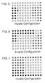
FIGS. 2-4 illustrate examples of valid configurations of ink drops applied
to a substrate in which a predetermined minimum distance (delta) is maintained
between each black dot and each color or composite black dot.
FIGS. 5-7 illustrate examples of invalid configurations of ink dots applied
to a substrate in that, in each example, at least one color or composite black dot is
located less than the minimum spacing from a black dot.
FIG. 8A illustrates a portion of a combined color plane which is partitioned
to form three rows by eight columns of blocks, each block consisting of eight
bytes of data.
FIG. 8B illustrates a portion of a color table in which each bit corresponds
to a respective one of the data blocks of FIG. 8A and indicates whether or not the
corresponding block has any color bits ON.
FIG. 9A illustrates a K (black) plane which is partitioned to form three
rows by eight columns of blocks in the same manner as the color plane of FIG.
8A.
FIG. 9B illustrates a portion of a black table in which each bit corresponds
to a respective one of the data blocks of FIG. 9A and indicates whether or not the
corresponding block has any K bits ON.
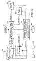
FIG. 10 is a conceptual diagram illustrating a method according to the
present invention of processing CMY color data for printing by a 4-color
(CMYK) liquid ink printing system so as to maximize use of black ink while
maintaining a predetermined minimum spacing between black blocks and color
blocks.
FIG. 11 is a flowchart of a process for determining whether a given block
of data is color, white or black, ie. whether a given block should be printed by the
color pen or the black pen.
FIG. 12 illustrates a portion of a color table in which one bit is ON, and
identifies the pertinent surrounding bits in the corresponding black table.
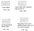
FIG. 13A is a portion of a color table with two bits ON.
FIG. 13B is the color table of FIG. 13A with neighbor bits turned ON.
FIG. 13C is a portion of a black table corresponding to FIGS. 13A and 13B.
FIG. 13D shows the resulting mask after logically ANDing the black table
of FIG. 13C with the mask of FIG. 13B.
FIG. 14A shows a portion of a color table in which the leftmost bit of one
byte is ON.
FIG. 14B is a portion of a black table corresponding to the color table of
FIG. 14A and indicating by 1's the bit adjacent the ON bit of FIG. 14A.
FIG. 14C is a portion of a color table in which the rightmost bit of a
selected byte is ON.
FIG. 14D is a portion of a black table corresponding to the color table of
FIG. 14C and indicating by 1's the bits adjacent the ON bit of FIG. 14C.
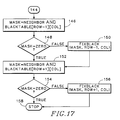
FIGS. 15-17 show a flowchart of a method of examining the color table
and black table to detect black blocks which are adjacent to color blocks.
FIG. 18 is a flowchart of a method of moving selected data into the color
planes from the black plane in order to correct minimum spacing violations.
FIGS. 19-21 illustrate operation of the invention as applied to a specific
example of a graphics image.
DETAILED DESCRIPTION OF THE PREFERRED EMBODIMENT
A. Introduction and Nomenclature
The colors Cyan, Magenta and Yellow are referred to as CMY. Black is
referred to as K (K instead of B, so as to not confuse this color with Blue). In an
example of a printer useful in connection with the present invention, two pens are
provided - one containing the color inks CMY and the other containing black ink.
These are called the color pen and the black pen, respectively. Black printed on
the page using the color pen (i.e. a combination of CMY) is called composite
black or process black. Hereafter, black printed on the page using the black pen
will simply be called black.
A dot (also called a pixel) is the smallest single area on the page that a pen
can place ink. For example, a commercial embodiment of the invention provides
for printing at a resolution of 300 Dots Per Inch (DPI) both vertically and
horizontally.
The input data to a printing system, or print data, indicates where to place
ink on the printed page in the form of bit-map planes. A plane conceptually is a
two-dimensional array of bits corresponding to a particular a page to be printed.
Each plane contains the data for one color. There may be three color planes, for
example CMY, as noted above. Any desired color may be obtained by
combinations of these colors. Other systems may use RGB (red-green-blue) color
planes, as is common in video display systems.
Each bit in a plane represents one dot location on the page. If the bit is on
(value 1), the ink for that color plane for that dot is printed. If the bit is off (value
0) nothing is printed for that color plane for that dot. Since all three color planes
are frequently considered together in this specification, we shall refer to "a bit in
the color planes" to mean the corresponding bits (i.e. those having the same
row/col location) in all three color planes. Similarly, we will refer to a "block of
data in the color planes" to mean the corresponding blocks of data in all three
color planes. In some systems, input data may comprise four planes, one each for
the colors CMY and one for black (K). Alternatively, the K plane may be derived
from the CMY color planes as explained below.
B. Restrictions on Ink Dot Positioning
The CMY inks and K ink are mutually exclusive, i.e. a dot can have either
some combination of CMY inks, or K ink, or no ink, but can never have a
combination of CMY inks and K ink. Accordingly, a dot can have one and only
one of the following printed on it:
C. Minimum Spacing
There is a further restriction on where the CMY and K inks can be placed
on the page. Along with not being able to be on the same dot, the CMY and K
inks cannot be within a predetermined minimum distance of each other. This
minimum spacing requirement varies with the print environment (e.g. paper
quality, temperature, humidity etc.). A useful minimum distance is two to three
dots. However, the problem of how close the CMY inks can be to the K ink is
complicated by the fact that, when two pens are positioned in an actual printer,
they can be mis-aligned. This misalignment can extend to a distance equivalent to
two to three dots. Consequently, in the preferred embodiment, the minimum
separation between CMY and K (black) inks is 6 dots (or pixels). In general, the
minimum spacing is referred to as delta. The actual number of dots depends
upon the application.
The distance 6 dots is a linear distance, for example 1/50th of an inch (at
300 DPI), which is also used for diagonal measures. FIG. 1 illustrates an array of
dot locations on a generally planar substrate such as a sheet of paper. Each dot
location is represented by a small open circle, except for one dot location at which
the circle is solid black. A circle about the solid black dot location illustrates a
radius of six dots. For example, if the dot array represented were 300 DPI, the
radius of the circle is approximately 1/50th of one inch.
If the solid black dot location represents a dot of black ink, then the circle
indicates which of the surrounding dots cannot be color or composite black.
Thus, any dot location that is on or within the circle cannot be printed by the color
pen. Conversely, if the dot in the center of the circle represents color or
composite black, then no dot that is on or within the circle should be printed with
the black pen.
A valid configuration of dots on a page is one that has no CMY ink within
delta dots of K ink. Figures 2 through 4 give examples of valid configurations of
ink drops on a page. In these figures, solid black circles represent a black dot(K
ink); shaded or hatched circles represent color or composite black dots (CMY
ink); and open circles represent white dots (no ink). FIGS. 5 through 7 illustrate
invalid configurations. In each of these figures, at least one CMY ink dot is
within delta (here six dots) of a black dot. Where the input data to a printing
system represents ink drop configurations that are invalid, i.e. that violate any of
above restrictions, the data must be modified before printing in order to maintain
print quality.
Since the bit plane data represent the inks that are printed on the page, the
restrictions described above concerning overlapping and minimum spacing
between color and black inks may conveniently be implemented by applying to
the restrictions to corresponding data in the bit planes. There can, for example, be
a bit turned on in the C and M planes for the same dot. There can never be a bit
turned on (or left on at print time) in the K plane and any of the CM or Y planes
for the corresponding dot, since this would violate the restriction that the CMY
and K inks must be mutually exclusive. If the same bit is on in all three CMY
planes, this represents a composite black dot. If no bit is on in any plane for a dot,
this is an empty dot (white space). Lastly, to implement the minimum spacing
restriction, if there is a bit turned on in the K plane, there cannot be a bit turned on
in the CM or Y planes within six dots of the corresponding bit location.
D. Data Structures
The method is preferably implemented in software, though special
hardware or a combination of the two may be used. Suitable code may be
executed to process the print data in any convenient location. For example, it may
be implemented in a "printer driver" program in a computer or in software in the
printer itself. In the preferred embodiment, three major data structures are
defined: the K plane, the color table and the black table. These will now be
discussed in detail.
1. The K plane
The K plane, as noted before, represents where to use the black pen on the
page. Each bit in the K plane represents one dot on the printed page. The K plane
thus has the same dimensions as the color planes. If a bit is on in the K plane,
none of the corresponding bits in the CMY planes can be on, nor can any of the
CMY plane bits be on within delta of the K plane bit. The K plane is represented
by reference number 60 in the diagram of FIG. 10.
2. The Color Table
The color table is a compressed representation of the CMY planes. It is
important to understand the relationship between the color table and the CMY
planes. Each bit in the color table represents a predetermined subset of the CMY
planes. In particular, each table bit represents a contiguous, rectangular array of
bits in the CMY planes called a block. To illustrate the concept, if the color
planes had dimensions 50 by 100 bits, they could be divided into, for example,
four equal, contiguous, rectangular arrays (blocks) of 25 by 50 bits each. In other
words, each block would be a quadrant of the color planes. If each such block is
represented by one bit in a color table, the color table would be two by two bits.
It may be said that the color data is compressed in this illustration by a factor of
1250 (i.e. 25 by 50 bits into one bit). (There is an additional factor of three, in
that three color planes (CMY) are compressed into one, for a total "compression"
of 3750:1)
It is advantageous for fastest processing, however, to "compress" the color
plane data in a manner based on the hardware byte size. In other words, to define
a block for a particular application so as to minimize machine instruction cycles,
as is familiar to those skilled in computer science. Since many processors use an
8-bit byte, each bit in the color table in a preferred embodiment represents one 8-bit
by 8-bit array in the CMY planes. Ergo, the size of a block in the preferred
embodiment is 8-bits by 8-bits. The individual color planes are represented by
reference numbers 54,56 and 58 in FIG. 10. The color table is 62 in the same
figure.
Additionally, the block size is selected to be at least equal to the minimum
spacing required between color dots and black dots. Recall that each data bit in
the color and K planes corresponds to a dot location on the printed page. Thus, an
8-bit by 8-bit block size is adequate as it exceeds, in both the vertical and
horizontal dimensions, the 6-dot minimum ink spacing requirement described
above. So a white block between color and black blocks ensures at least the
minimum spacing. For example, if the color table has a zero bit, indicating no
color bits for a particular block, then it would be permissible to have black ink to
one side of that block, and color ink(s) to the other side of that block, as there
would be at least eight white bits in between (the intervening block). This
exceeds the 6-dot delta minimum spacing requirement, while obviating the need
to explicitly check each one of the intervening bits.
FIG. 8A illustrates the concept of a "combined" color plane. Such a
combined plane of data may not actually be formed, but is useful here for
explaining how data is processed according to the invention. The combined
plane represents the logical OR function of all three (CMY) color planes, except
that it excludes (i.e. indicates as zero or off) bits which are on in all three color
planes. In this regard, it is not precisely the logic function: C OR M OR Y.
Rather, it is the logic function: C OR M OR Y AND NOT (C AND M AND Y).
Thus, if a particular bit is on in any of the three color planes, but not on in all
three color planes, then the corresponding bit will be on in the combined color
plane. This combined plane therefore indicates color, but not composite black.
The data is partitioned to define a regular array of blocks. In the figure, there are
three rows (numbered 1-3) by eight columns (numbered 1-8) in the array. Each
block consists of 8 bytes of data.
FIG. 8B shows three bytes of a color table corresponding to the combined
color plane of FIG. 8A. Each byte in FIG. 8B corresponds to a row in FIG. 8A;
each bit corresponding to one block of data. In FIG. 8A, note for example that the
8 by 8 block for row 1, column 1 of the color plane has bits turned on (value 1),
so the bit that represents that block in the color table is also turned on. Blocks in
the color plane that have no bits turned on (value 0) are represented in the color
table with a zero, as noted above. Even if only one bit is turned on in a block, as
appears in row 3, column 2, the corresponding bit in the color table is turned on.
The color table of FIG. 8B therefore indicates which blocks in the CMY color
planes have color but not composite black.
3. The Black Table
The black table is a compressed representation of the K plane data. The
same 8-bit by 8-bit block size is used as in the color table. Accordingly, the black
table and the color table are the same size, and each bit location in each table
corresponds to the same block location in the K-plane and in the color planes,
respectively. FIG. 9 shows the relationship between the K plane (FIG. 9A) and
the corresponding black table (FIG. 9B). The relationship is essentially the same
as that described with respect to FIG. 8, bearing in mind that all three color planes
(not shown individually) affect the color table, while the black table reflects
solely the single K plane.
In a preferred embodiment, it is advantageous to surround both the color
and black tables with an extra byte (along the top, left, right and bottom edges of
the array). These extra bytes are not essential, but they simplify dealing with the
special cases of conducting spacing checks (detailed below) along the table edges.
Essentially, where an extra byte is provided along an edge of a table, all of the
actual data can be processed as explained below, without "running out of data"
along the edges of the actual data. Use of these edge or margin bytes will be
apparent to those skilled in computer science in light of this specification and the
accompanying drawings.
E. Building the Color Table, Black Table and initial K Plane
FIG. 10 provides an overview of the above data structures and their
relationships to the principal steps in the new color separation method. The major
steps, in general, are as follows. First, in step 52, is building the color and black
tables that represent in a compressed format CMY and K (black) regions on the
printed page. Also, building an initial K plane of data. Next, step 66, is
examining the color and black tables to detect color blocks adjacent to black
blocks. If such adjacency is detected, changing the adjacent black block to a color
block by moving the corresponding K plane data into the color planes for printing
as composite black (also part of step 66), thereby enforcing the minimum ink
spacing requirements. After there are no black blocks adjacent to color blocks,
processing is complete and the color separation is done, stop 68.
Initially, the CMY planes (54,58,56) are loaded with the image to be
printed by the windowing system or application. If black is to be printed, the
same bit will be on in the CM and Y planes. In step 52, the CMY planes are read
and the color and black tables are created as detailed below. Also, the initial K
plane 60 is created. This initial K plane is a first attempt at performing color
separation, but it may be modified later. Each block will correctly be designated
as being either black, color, or white. No attempt is made at this stage (step 52) to
look at adjacent blocks, i.e. a color block next to a black block. Next these
procedures are described in greater detail.
In building the color table, black table and initial K plane, the CMY planes
are examined in 8-bit by 8-bit blocks. Each block will be designated as being in
one (and only one) of the following three states:
FIG. 11 is a flowchart of a procedure for making these state determinations
to build the color and black tables. The color and black tables are initially set to
all zeros. The procedure illustrated by the flowchart of FIG. 11 is performed once
for each 8 by 8 block on a page. Each byte in the block is examined until it can
be determined which of the three states - color, black, or white - the block is in.
In this description, the block under examination is called the "current block".
Referring to FIG. 11, a variable called row indicates which byte (in the
current block) is being examined. The indicated byte is referred to as the "current
byte" The procedure begins at step 70 by setting row equal to 1, representing the
first byte of the current block. Step 72 tests for the end of the block, given that a
block has only 8 rows. Since row is not equal to 9, the method proceeds to step
74. Step 74 tests whether the C, M OR Y byte ≠ 0. If the current byte in each of
the CM and Y planes is zero, then current byte represents white space. In that
case, we proceed via step 96 to the next byte in the block by incrementing row in
step 92.
Alternatively, if the current byte in any of the CM or Y planes is not equal
to zero, then the current byte is either a color byte or a black byte. Step 76
determines which one it is. If the C plane byte equals both the M and Y plane
bytes, then this byte is composite black.
Data corresponding to the current composite black block is presently
represented in the CMY planes. Step 78 copies the data from the C plane to the K
plane. Because there is now data in the K plane, the corresponding bit in the
black table is turned on (also in step 78). In step 80, the corresponding bytes in
the CMY planes are zeroed out (cleared), since the data is now represented in the
K plane. Thus, for the current byte, the data has been moved from the CMY
planes to the K plane. The method next proceeds (step 82) to examine the next
byte in the current block. The foregoing steps 92, 72, 74, 76, 78 and 80 are
repeated as long as composite black bytes are found.
If (or when) step 76 determines that the current byte is a color byte, i.e.
there are bits on in CM or Y that are not the same in all three, then the entire
current block must be designated as a color block, by definition. Accordingly, in
step 84, the bit in the color table that corresponds to this block is turned on. Next,
in step 86, we test whether or not (e.g. by a flag) black has been detected
previously within the current block. (A "black detected" flag would be cleared
after each block.) Note that, if black had been found in any of the previous bytes,
two things have already happened. First, the CMY data that represented black in
an earlier byte was moved to the K plane and erased from the CMY planes.
Second, the bit in the black table that represents the current block has already
been turned on.
The earlier move of black data from the color planes into the K plane is
consistent with the preference given to using black (rather than composite black)
wherever possible. Now, however, we have determined that there is color within
the same block. Since black is not allowed within the same block as color, we
must use composite black for all black within this block. The color pen (CMY)
must used to print that data.
Therefore, the next step 88 is copying data that had been determined to be
black in the previous bytes from the K plane back into the CMY planes. Also,
step 88 turns off the bit in the black table that represents this block. Once color
has been found, the process is complete for the current block (step 94). If a block
has no data in the CMY planes, the procedure will loop through steps 72, 74, 96,
92 and find nothing.
After the procedure illustrated in FIG. 11 has been applied to each block in
the CMY planes, each block has been designated as color, black or white. If a
block is color, the corresponding bit is on in the color table only. For black, the
corresponding bit is on in the black table only. For white, the corresponding bits
are off in both the color and black tables. Now that the state of each block of data
has been correctly determined and entered in a table, those tables can be used
advantageously for further processing the data at high speed.
F. Examining the Data to Detect Spacing Violations
The next step, according to the invention, is to examine each color block,
and determine if there are any black blocks adjacent to it. If there is no black
block adjacent a color block, then the data does not call for printing black ink
within one block (i.e. within eight dots or pixels) of color ink. This criterion more
than satisfies the six-dot minimum spacing required to avoid adversely affecting
the inks on the printed page.
An adjacent black block can occur in any one of 8 surrounding locations
relative to the color block; namely, to either side (in the same row), above or
below (in the same column), or diagonally adjacent (i.e. offset by one row and
one column in any of the four diagonal directions). The blocks of data are
examined implicitly by examining the corresponding tables, where each block is
represented by a single bit. Referring now to FIG. 12A, a color table, one bit is
turned on. FIG. 12B identifies the surrounding bits, represented by 1's, that must
be checked in the black table. If any one of the surrounding bits in the black
table is on or a 1, it signifies that there is a black block adjacent to a color block.
Thus, the color and black tables can be used to quickly determine where color
blocks are adjacent to black blocks.
It would be excessively time consuming, however, to examine each bit in
the color table to determine which bits are turned on, and then identify what
surrounding bits to look at in the black table, and then examine each of those
surrounding bits explicitly. A faster method of determining when a color block is
adjacent to a black block calls for examining bytes instead of bits in the color and
black tables, as follows.
1. Using Neighbor Bytes
Note that in FIG. 12, for a given 1 bit in the color table, three bits above
and three bits below must be checked in the black table. Additionally, the two
bits immediately left and right of the corresponding color bit must be checked in
the black table. This can be done quickly and efficiently using "masks" as
follows. The first step, for a given 1 bit in the color table (a "color bit"), is
turning on its neighbor bits to the left and to the right of the color bit. This is
called "smearing" the color bit. We call the resulting byte a neighbor byte. The
next step is logically ANDing the neighbor byte with each byte in the black table
that is located in the same column in the row above, the same row, and the row
below the current byte in the color table. The result of each ANDing operation is
called a mask. For each such AND operation, if the resulting mask is a value not
equal to zero, it indicates that there is a 1 or on bit in the black table (a "black
bit") located adjacent the location that corresponds to the color bit. Each such
black bit represents a black block adjacent the color block represented by the
color bit.
This technique is illustrated in FIG. 13. FIG. 13A shows an excerpt from a
color table, having a byte (in the second row) with two bits on. FIG. 13B shows
the came color table with the left and right neighbor bits turned on (the neighbor
byte). FIG. 13C shows the corresponding bytes in an exemplary black table.
Finally, FIG. 13 D shows the resulting mask after logically ANDing each byte in
the black table of FIG. 13 C with the neighbor byte of FIG. 13B.
The step of creating a neighbor byte (see FIG. 13B) can be implemented at
very high speed as follows. For each byte in the color table there are 256 possible
combinations of bits, and there are 256 corresponding patterns of bits (or neighbor
bytes) after the neighbor bits have been turned on. These neighbor bytes can be
pre-computed and stored in an array (called neighborarray) having 256 entries.
Each time the process detects one or more bits on in a color table byte, that color
table byte can be used as an index into the neighbor byte array to look up the
corresponding neighbor byte. This lookup procedure is represented by step 98 in
FIG. 15, in which the neighbor byte array is called neighborarray.
Referring now to FIG. 15, the first step 98 is to fetch the neighbor byte for
the current color table byte. A variable (called neighbor) is loaded with the
appropriate neighbor byte from the look-up table (neighborarray) specified by
the current byte (colortable[row][col]). This variable (neighbor) will be used to
quickly determine whether there are any black blocks adjacent to the color blocks
represented by the current byte in the color table. Specifically, in step 100,
neighbor is logically ANDed with the black table byte in the same row/column
location (blackTable[row][col]) to see if there are color blocks adjacent to black
blocks. The result byte is called mask.
The next step 102 is testing to determine whether the mask resulting from
the previous AND operation is equal to zero. If it is not (false), then there are
color blocks adjacent to black blocks. Each on bit (1) in the resulting mask
indicates an on bit in the black table byte adjacent the corresponding bit in the
color table. (Note that each bit in the black table byte that corresponds to an on
(1) bit in the color table byte is necessarily off (0) as black table bits and color
table bits are mutually exclusive.) This is corrected, step 120, by calling a
function called fixBlack, described in detail below. Briefly, fixBlack is a
procedure that, for a given mask pattern and row/column pair in the color/black
tables, moves the corresponding block of K plane data back into the CMY planes.
For each block moved, the corresponding black table bit is turned off and the
corresponding color table bit is turned on.
2. Special case - Leftmost Bit in Color Table Byte
The above technique does not address the case in which the "neighbor" bits
to be examined in the black table are in a different byte to the left or right. In
other words, when the color table bit of interest (a "1") is at either end of the byte,
three of the neighbor bits in the black table are in a neighboring byte (adjacent the
corresponding byte) and must be inspected explicitly. Thus, if the leftmost bit of
a color table byte is on, then the rightmost bit of the black table bytes to the left
of, upper left of, and lower left of the corresponding byte in the black table must
be checked. Similarly, if the rightmost bit of a color table byte is on, then the
leftmost bit of the black table bytes to the right of, upper right of, and lower right
of the corresponding byte in the black table must he checked explicitly. Figure 14
illustrates this relationship.
Referring now to FIG. 14, FIG. 14A shows a color table in which the
leftmost bit of a byte is on. FIG. 14B shows the corresponding portion of a black
table, in which the bits indicated with a "1" and numbered 200, 202 and 204 must
be checked to see if the corresponding blocks contain black. FIG. 14C shows
another color table in which the rightmost bit of a byte is on. FIG. 14D shows
the corresponding portion of a black table, in which the bits indicated with a "1"
and numbered 206, 208 and 210 must be checked to see if the corresponding
blocks contain black. Accordingly, a procedure for checking adjacent bits must
be able to cross byte boundaries in these special cases.
In general, if any bit is on in a color table byte, it is necessary to detect
every occurrence of a black table bit that is on adjacent the bit location in the
black table that corresponds to the on color table bit. FIG. 15 is a flowchart of a
procedure (called findBlack) for this purpose. findBlack is passed the address,
i.e. the row and column indexes, of the byte in the color table that has at least one
bit on (the current byte). It is located at colortable[row][col].
If step 102 result is True, there is no conflicting bit in the black table within
the current byte. However, it remains to check for the special cases noted above.
First, step 104, is determining whether the leftmost bit in the current color table
byte is on. This is conveniently (and quickly) done by logically ANDing the
current byte (colortable [row][col]) with the number 128 and checking for zero-step
104. If the leftmost bit is not on (step 104=True), then checks of all three
bytes in the black table to the left (above, same row, and below) can be skipped,
so control passes to 124 (FIG. 16). If the result of step 104 is False, then the
leftmost bit of the current (color table) byte is on. Therefore, it remains to
examine adjacent black table bytes to the left, as follows.
In step 106, the indexes for the black table are [row-1] and [column-1].
This location corresponds to bit 200 in FIG. 14B. This byte in the blacktable is
ANDed with the number 1 and the result checked for zero in step 106. In other
words, the "mask" is a binary one, which is a byte with only the rightmost bit
turned on. If the result of step 106 is False, the rightmost bit of this black table
byte is on, adjacent to (above and left of) the leftmost bit of the color table byte.
Accordingly, in step 108, fixBlack is called to move the corresponding black
block to the CMY planes. If the result is True, the rightmost bit of this black table
byte is off (zero), and we proceed to step 110 directly without calling fixBlack.
Next, in step 110, the black table byte at [row], [column-1] is examined.
This location corresponds to bit 202 in FIG. 14B. If the rightmost bit of that byte
Is on, i.e. step 110 result=False, the rightmost bit of this black table byte is on,
adjacent to (left of) the leftmost bit of the color table byte. Accordingly, in step
112, fixBlack is called to move the corresponding black block to the CMY
planes. If the result is True, the rightmost bit of this black table byte is off (zero),
and we proceed to step 114 directly without calling fixBlack.
Finally, in step 114, the black table byte at [row+1], [column-1] is
examined. This location corresponds to bit 204 in FIG. 14B. If the rightmost bit
of that byte is on, i.e. step 114 result=False, the rightmost bit of this black table
byte is on, adjacent to (below and left of) the leftmost bit of the color table byte.
Accordingly, in step 116, fixBlack is called to move the corresponding black
block to the CMY planes. If the result is True, the rightmost bit of this black table
byte is off (zero), and we proceed to step 124 (FIG. 16) directly without calling
fixBlack.
At this point, for the current color table byte, the same byte in the black
table has been checked, and if necessary, the three bytes to the left have been
checked. What is left to do is check the bytes above, below and to the right of this
color table byte.
3. Special case - Rightmost Bit in Color Table Byte
Referring now to FIG. 16, refer to label 124. The first step 126 is to
examine the rightmost bit of the current color table byte. This is done by
logically ANDing the byte with the binary number 1 and testing the resulting byte
for zero - step 126. If the rightmost bit is on, result =False, each of the three
adjacent bytes to the right in the black table must be checked to see if the leftmost
bit is turned on. This process corresponds to checking bits 206, 208 and 210 in
FIG. 14D. If the rightmost bit of the color table is not on, result=True, these
checks can be skipped, so go to label 144 (FIG. 17).
Each of these bytes is checked in turn, in step 128 (above and to the right);
step 132 (same row - to the right); and step 136 (below and to the right). The
procedure is similar to that employed for checking bytes to the left side, described
above, so detail may be omitted. Note however that in FIG. 16 the adjacent bytes
are ANDed with the number 128 so as to detect the leftmost bit in the blacktable
byte, whereas the mask used in FIG. 15 was the number 1 to detect the rightmost
bit. After checking each black table byte, the fixBlack procedure is called, as
described above, to move data as necessary.
4. Testing Bytes Above and Below the Current Byte.
Lastly, the bytes above and below must be checked. More precisely, it
remains to examine the black table bytes above and below the black table location
corresponding to the current color table byte. Referring now to FIG. 17, start at
label 144. In the first step 146, mask is set to the value of neighbor logically
ANDed with the byte from the black table above the color table byte. Thus, the
black table index is set to [row -1][ col]. Recall that the value neighbor
corresponds, for example, to the byte shown in FIG. 13B. It is the current color
table byte with neighbor bits turned on. If the corresponding black table bytes are
as shown in FIG. 13C, the results after ANDing each black table byte with the
neighbor byte are as shown in FIG. 13D.
The next step 148 checks to see if the resulting value is equal to zero. If it
is not equal to zero (False), there are black blocks adjacent to color blocks, and
fixBlack is called with the appropriate values in step 150. The next step is to
examine the black table byte below the color table byte. If the result of step 148
is True, we proceed to the next test without calling fixblack in step 150.
The next step 152 is to set mask to the value of neighbor ANDed with the
byte from the black table below the color table byte. Thus, the black table index
is set to [row+1][ col]. Step 154 checks to see if the resulting value is equal to
zero. If mask is not equal to zero (False), there are black blocks adjacent to color
blocks, and in step 156 fixBlack is called to correct the violation. If mask is equal
to zero (True), the process is completed and stops 158.
At this point, for the current color byte only, the method has checked all
possible surrounding bits in the black table. For any black block adjacent to a
color block, that black block was moved from the K plane back to the CMY
planes, and the color and black tables updated accordingly. The foregoing
procedures illustrated in FIGS. 15-17 are repeated for each byte in the color table
that has any bits on. In other words, they are carried out for all blocks in the color
table that have at least one bit on.
G. Moving data from the K plane to CMY planes (fixBlack)
A preferred method of moving data from the black K plane back into the
CMY color planes is arbitrarily called fixblack, as noted above. This method is
illustrated in the flowchart of FIG. 18. The function fixBlack is passed three data
- mask, row and col (column). Row and column are the address or index of the
current byte. fixblack is called when that byte in the color and black tables
represents black adjacent to color. The mask, itself a byte, indicates (by a 1)
which bit in the current byte represents the black block to be moved. More than
one bit may be on in the mask.
Referring to FIG. 18, in the first step 160, a value called bit is initialized to
128, the leftmost bit of a byte. The bit will be shifted to the right, and at each
shift, will be used to see if the same bit is on in the mask. If so, then this is a
block that must be moved from the K plane to the CMY planes. Step 162 checks
that the value of bit is still greater than zero. If so, bit is ANDed with the mask
in step 164. If the result is not equal to zero (False), then in step 166 the K plane
data represented by this bit in the black table is moved to the CMY planes. Next,
in step 168, the bit value is shifted right by one, and the testing continues for the
rest of the byte.
After each of the eight bits in the mask are tested, the black and color tables
must be updated. In step 170, the black table byte is replaced by itself logically
ANDed with the binary complement of mask. In computer shorthand:
blackTable[row][col] = blackTable[row][col] AND NOT mask
This step turns off the mask bits in the black table. Next, in step 172, the color
table byte is ORd with the mask, thereby turning on the mask bits in the color
table.
Importantly, for the current byte in the color table, there are now new
entries. The corresponding new color blocks might be adjacent to existing black
blocks, which would violate the minimum spacing requirements. Therefore, in
step 174, findBlack must be called (again) for the current row/column.
findBlack refers to the procedures for finding and correcting adjacency
violations, detailed above with reference to the flowchart of FIGS. 15-17. The
methods called findBlack and fixBlack may be arranged to operate recursively,
though that is not essential. The specific implementation is a matter of design
choice, as long as processing continues until all minimum spacing violations are
detected and corrected. Is some cases, as shown below, changing data can
"propagate" over an entire page.
H. Example Illustrating Operation of the Invention
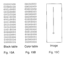
FIGS. 19-21 illustrate an example of operation of the invention. FIG. 19C
illustrates a graphics image. In that image, the vertical line is to be printed black.
At the lower end of the vertical line is a circle indicating color ink. The black line
thus abuts the color ink. In CMY color plane data, the black line would be
represented as composite black, and the circle as the desired color.
Initially, all of the composite black data is moved out of the color planes
and into a K plane for printing as true black. FIG. 19A shows the contents of a
black table and FIG. 19B shows the contents of a color table after this initial
processing has been completed. Only a single bit remains on in the color table
(row 12), indicating the color ink (the circle) in the image of FIG. 19C. A series
of 1's in the black table now represent the vertical black line in the image. The
initial table building corresponding to step 52 in FIG. 10 has been completed.
The next step is to examine these tables to detect black adjacent color and
make any necessary corrections. When the sole color bit is examined, the method
will detect an adjacent black bit, namely the black bit directly above the black
table location that corresponds to the color bit. Specifically, in step 146 (FIG.
17), mask=0011 1000 (neighbor) AND 0001 0000 (blackTable [row-1][col]).
The result is 0001 0000, so step 148 (mask=zero?) result is False. Accordingly,
in step 150, fixBlack is called to correct the minimum spacing violation.
fixBlack is passed the mask to identify the offending table bit, and the table row
and column locations. In this example, fixBlack receives the parameters: 0001
0000 (mask), 11 (row eleven), 1 (column 1 -- only one column in the example).
fixBlack moves the corresponding block of data from the K plane back into the
color planes, and updates the black and color tables accordingly (see FIG. 18). As
a consequence, the bit directly above the color bit in FIG. 19B is turned on. And
the corresponding bit in the black table is turned off.
Next findBlack is called, i.e. the procedure of FIGS. 15-17, to check the
black table bits surrounding the new color table bit (in row 11) to detect black
adjacent color once again. The black table bit in row 11 is now off, and is not at
issue. But the black table bit in row 10 is detected as being adjacent the color
table bit in row 11. Therefore, as before, the corresponding block of data is
moved from the K plane back into the color planes. The tables are updated, i.e.
the color table bit in row 10 is turned on, and the black table bit in row 10 is
turned off.
Once again the current color table bit, now row 10, is examined to detect
adjacent black bits in the black table. The black bit in row 9 will be detected and,
as before, the corresponding block of data moved from the K plane back into the
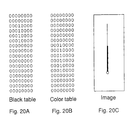
color planes. It may be seen that the foregoing steps are repeated, each cycle
moving a block of data from the K plane back into the color planes. After five
cycles, the data are as illustrated in FIG. 20A (black table) and FIG. 20B (color
table). The data shown in the tables of FIG. 20 is represented by the image of
FIG. 20C. Referring to FIG. 20C, the heavy (lower) portion of the vertical line
represents composite black, while the finer (upper) portion of the line represents
true black. This illustrates graphically how the composite black is "propagating"
up from the color region.
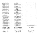
Note that, at this point in the process, a violation of the minimum spacing
requirement still exists where the composite black touches black, since composite
black is composed of color ink. Referring to the tables of FIG. 20, it may be seen
that the color bit in row 7 is adjacent (below) a black bit in the same position in
row 6. Accordingly, the foregoing process continues until all of the black data
has been converted back into composite black data. The final result appears in the
tables of FIG. 21A (black table) and FIG. 21B (color table). The data shown in
the tables of FIG. 21 is represented by the image of FIG. 21C. In that image. no
black ink is printed adjacent color ink. It may be observed, in this example, that
correction of an initial adjacency violation resulted in a new violation, correction
of which resulted in yet another new violation, etc., so that the correction
"propagated" over the entire image.