EP0539056B1 - Automotive electronics module - Google Patents
Automotive electronics module Download PDFInfo
- Publication number
- EP0539056B1 EP0539056B1 EP92309142A EP92309142A EP0539056B1 EP 0539056 B1 EP0539056 B1 EP 0539056B1 EP 92309142 A EP92309142 A EP 92309142A EP 92309142 A EP92309142 A EP 92309142A EP 0539056 B1 EP0539056 B1 EP 0539056B1
- Authority
- EP
- European Patent Office
- Prior art keywords
- cover
- housing
- weld
- module
- abutting
- Prior art date
- Legal status (The legal status is an assumption and is not a legal conclusion. Google has not performed a legal analysis and makes no representation as to the accuracy of the status listed.)
- Expired - Lifetime
Links
Images
Classifications
-
- B—PERFORMING OPERATIONS; TRANSPORTING
- B60—VEHICLES IN GENERAL
- B60R—VEHICLES, VEHICLE FITTINGS, OR VEHICLE PARTS, NOT OTHERWISE PROVIDED FOR
- B60R16/00—Electric or fluid circuits specially adapted for vehicles and not otherwise provided for; Arrangement of elements of electric or fluid circuits specially adapted for vehicles and not otherwise provided for
- B60R16/02—Electric or fluid circuits specially adapted for vehicles and not otherwise provided for; Arrangement of elements of electric or fluid circuits specially adapted for vehicles and not otherwise provided for electric constitutive elements
- B60R16/023—Electric or fluid circuits specially adapted for vehicles and not otherwise provided for; Arrangement of elements of electric or fluid circuits specially adapted for vehicles and not otherwise provided for electric constitutive elements for transmission of signals between vehicle parts or subsystems
- B60R16/0239—Electronic boxes
Definitions
- the present invention relates generally to automotive electronic control modules. More particularly, the present invention relates to an automotive electronic module enclosing electronic circuitry which is sealed hermetically by vibration welding.
- Automotive underhood electronic modules typically contain delicate circuitry such as integrated circuits, power circuit boards and the like used in various operating systems within the vehicle, such as an anti-lock brake system, an engine control system, multiplex system and others. During use, these modules are subjected to extremely harsh conditions such as heat, moisture, and vibration which could have deleterious effects upon the circuitry within the module if the modules are not sealed. Typically, the modules are sealed with a glue such as shown in U.S. Patent No. 3,909,504 and/or are filled with a resin or potting material, such as shown in U.S. Patent Nos. 4,546,412 and 4,899,257.
- a glue such as shown in U.S. Patent No. 3,909,504 and/or are filled with a resin or potting material, such as shown in U.S. Patent Nos. 4,546,412 and 4,899,257.
- Gluing processes are used in sealing the modules to control the amount of vibration imposed on the module to limit damage to the delicate circuitry inside.
- gluing the modules to seal them is a time-consuming manufacturing process. It would be advantageous to provide an alternative manufacturing process for sealing the modules.
- Vibration welding is a manufacturing process by which two work pieces are reciprocated linearly relative to one another under the application of a force, causing the mating surfaces of the work pieces to soften under the influence of friction. After a weld time interval, the work pieces are returned to their original position and they are held in forced contact for a sufficient length of time for the mating surfaces to solidify. Upon solidification, the force ceases and the work pieces are bonded together.
- a technique is shown in U.S. Patent No. 4, 377, 428. In Ultrasonics vol.5 no.
- the present invention provides a method for hermetically sealing an electronics module enclosing electronic circuitry, said module including a housing for receiving the circuitry therein, connection means disposed in said housing for providing electrical connection to said circuitry, and a cover enclosing said connection means, the method comprising the steps of:
- the present invention also provides an electronics module enclosing electronic circuitry, said module including;
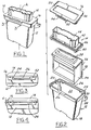
- FIG. 1 shows a perspective view of an anti-lock brake system electronics control module 10 which encloses electronic circuitry for controlling an anti-lock brake system of a vehicle.
- the anti-lock brake system module 10 will be used as an example only in the description of the present invention.
- the module 10 is fabricated from a thermoplastic material, such as ABS, glass-filled nylon, polyester, polypropylene or any of a number of known thermoplastic materials suitable for use in the underhood environment of an automobile.
- the module 10 comprises a housing 12 which receives the electronic circuitry therein and a connector 14 for providing electrical connection between the electronic circuitry in the housing 12 and the vehicle.
- the module also includes a cover 16 for enclosing the module.
- the housing 12 includes a closed-end 18, an open-end 20 and a receiving volume 22 defined therebetween for receiving the electronic circuitry therein.
- the open-end 20 of housing 12 includes a circumferential edge 24 extending therearound.
- a pair of locking tabs 26 depend from the circumferential edge 24 temporarily hold the control module assembly together prior to the sealing of the module.
- the housing 12 also includes a pair of securing tabs 28 having apertures 30 therein for receiving threaded fasteners to connect the module 10 to the vehicle.
- the receiving volume 22 is configured to receive the electronic circuitry, such as shown at 32.
- the electronic circuitry includes a power circuit board 34 containing the control electronics, such as are commonly known in the art.
- the circuit board is connected to a heat sink 36, typically manufactured of extruded or die cast aluminium as well as a plurality of connector pins 38.
- the connector pins 38 provide electrical connection means between the circuit board 34 and a mating male connector (not shown) disposed in the vehicle.
- the circuit board 34 is connected typically to the heat sink through the use of screws or clips, although the present invention is not meant to be limited to the circuitry described herein.
- the module 10 shown in Figure 1 further includes a connector 14 having a base portion 40 and a rectangular vertical wall 42 projecting perpendicularly therefrom.
- the vertical wall 42 defines a volume 44 into which a male mating connector is disposed to connect the vehicle to the control module 10.
- the connector 14 provides connection means for providing electrical connection between the module and the vehicle.
- the connector 14 further includes a circumferential lip 46 extending therearound. As can be seen in Figure 4, the circumferential lip 46 causes a space (d) between the cover 16 and the housing 12 in the assembled, but unsealed condition as will be described below.
- the circumferential lip 46 of the connector is configured to abut a generally planar portion 48 of the cover 16.
- the cover 16 is a generally planar member having the planar portion 48 and an aperture 50 defined therein through which pass the vertical walls 42 of the connector 14.
- the cover 16 also includes a pair of locking clips 52 having an elongated slot 54 therein for mating engagement with the tabs 26 of the housing 12.
- the clips 52 temporarily hold the module 10 into an assembled condition prior to the hermetic sealing of the module by the method of the present invention.
- the elongated slot 54 has a length greater than the length of the tabs 26 of the housing 12. As will be explained herein, this allows for the relative linear reciprocal movement of the cover 16 and the housing 12.
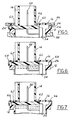
- Figures 5, 6 and 7, show a cross-sectional view of the upper portion of the module 10 of Figure 1 in the succeeding stages of sealing the module 10 according to the method of the present invention.
- Figure 5 shows the module 10 in an assembled, but unsealed condition, wherein the clips 52 of the cover 16 have engaged the locking tabs 26 of the housing.
- the cover 16 is shown as being press fit or interference fitted into an upper platen 56 of a vibration welding machine while the housing 12 is fit by an interference fit into a lower platen 58 of the vibration welding machine.
- the upper platen 56 and lower platen 58 comprise a first and second support means configured to undergo relative linear reciprocating motion along an axis perpendicular to the longitudinal axis of the housing (A) during the vibration welding of the module.
- the circumferential lip 46 of the connector 14 and the planar portion 48 of the cover 16 define a first abutting contact surface 60 resulting in the spacing (d) described earlier.
- the upper platen 56 and lower platen 58 reciprocate linearly relative to one another along an axis (A) perpendicular to the longitudinal axis of the housing (A) for a weld time of between one and three seconds.
- the upper platen provides a force, relative to the lower platen, sufficient to produce a pressure at the weld contact surface of between 13,8-17,2 bar (200-250 pounds per square inch), while the upper platen 56 reciprocates at a minimum frequency of 150 Hz. In the preferred embodiment, the upper platen 56 reciprocates relative to the lower platen 58 at an approximate frequency of 240 Hz.
- the application of the force causes the abutting contact surface 60 to melt forming a weld contact surface 62 between the circumferential lip 46 of the connector 14 and the planar portion 48 of the cover 16 as shown at 62 in Figure 6.
- a second abutting contact surface 64 is defined between the circumferential edge 24 of the housing 12 and the planar portion 48 of the cover 16. While the weld at contact surface 62 is still molten, the upper platen 56 and lower platen 58 maintain the reciprocal linear motion while still maintaining the predetermined applied force. This causes the weld contact surface 62 to remain molten while a second weld contact surface, 66 in Figure 7, is formed between the circumferential edge 24 of housing 12 and the planar portion 48 of the cover 16.
- the reciprocating motion is stopped but the force is maintained until the first and second weld surfaces can rigidify, in approximately one second.
- the cover 16 becomes simultaneously welded to the connector 14 and the housing 12 along two weld surfaces, 62, 64.
- the upper and lower platens are moved apart and the module is then removed from the lower platen and is ready to be installed into a vehicle.
- the cover of the module may be sealed hermetically to a housing directly, without the intermediate step of sealing the cover to a connector.
Description
- The present invention relates generally to automotive electronic control modules. More particularly, the present invention relates to an automotive electronic module enclosing electronic circuitry which is sealed hermetically by vibration welding.
- Automotive underhood electronic modules typically contain delicate circuitry such as integrated circuits, power circuit boards and the like used in various operating systems within the vehicle, such as an anti-lock brake system, an engine control system, multiplex system and others. During use, these modules are subjected to extremely harsh conditions such as heat, moisture, and vibration which could have deleterious effects upon the circuitry within the module if the modules are not sealed. Typically, the modules are sealed with a glue such as shown in U.S. Patent No. 3,909,504 and/or are filled with a resin or potting material, such as shown in U.S. Patent Nos. 4,546,412 and 4,899,257. Gluing processes are used in sealing the modules to control the amount of vibration imposed on the module to limit damage to the delicate circuitry inside. However, gluing the modules to seal them is a time-consuming manufacturing process. It would be advantageous to provide an alternative manufacturing process for sealing the modules.
- US-A-3 909 504 discloses the features defined in the preamble of claims 1 and 9.
- Vibration welding, or friction welding, is a manufacturing process by which two work pieces are reciprocated linearly relative to one another under the application of a force, causing the mating surfaces of the work pieces to soften under the influence of friction. After a weld time interval, the work pieces are returned to their original position and they are held in forced contact for a sufficient length of time for the mating surfaces to solidify. Upon solidification, the force ceases and the work pieces are bonded together. Such a technique is shown in U.S. Patent No. 4, 377, 428.
In Ultrasonics vol.5 no. 17, January 1967, page 17 "Ultrasonic Welding" there is described a system for the ultrasonic welding of plastics materials using a work horn which transmits vibrations generated by a piezoelectric transducer. The horn has a tip which is applied to the workpiece to transmit ultrasound through the workpiece to reach a joint to be welded. The upper surface of the joint vibrates while the lower surface remains stationary and the relative motion generates frictional heat which melts the surfaces of the joint. The vibrations applied to the workpiece pass through the horn tip while the tip is pressed against the workpiece and consequently the vibrations are aligned with the axis of the pressure applied through the horn. It has been heretofore unknown to use vibration welding to seal hermetically an electronics control module for a vehicle because of the potential damage which may be inflicted upon the internal circuitry of the module during the relative vibration of the sealing parts. - It is an object of the present invention to seal hermetically automotive electronic modules containing delicate electronic circuitry therein by vibration welding. These and other objects, features and advantages of the present invention will become apparent from the following summary, description, and claims which follow.
- The present invention provides a method for hermetically sealing an electronics module enclosing electronic circuitry, said module including a housing for receiving the circuitry therein, connection means disposed in said housing for providing electrical connection to said circuitry, and a cover enclosing said connection means, the method comprising the steps of:
- assembling said circuitry and said connection means in said housing;
- bringing a portion of said cover into abutting contact with a circumferential portion of said housing and;
- causing thermoplastic material along said abutting portions to melt to form a weld surface and thereafter to rigidify to weld said cover to said housing along said weld surface;
- supporting said housing in a first support means;
- supporting said cover in a second support means to dispose the planar portion thereof into abutting contact with a circumferential edge of said housing;
- applying a force to said cover in a direction parallel to the longitudinal axis of said housing for causing said cover to be in abutting surface contact with said circumferential edge and;
- causing said first and second support means to undergo relative linear reciprocating motion along an axis perpendicular to the longitudinal axis of said housing during a predetermined weld time interval for causing thermoplastic material along said respective abutting contact surfaces to melt to form a weld surface, and upon cessation of said reciprocating motion, to rigidify said weld surface, whereby said cover becomes welded to said housing along said weld surface.
- The present invention also provides an electronics module enclosing electronic circuitry, said module including;
- a housing for receiving the circuitry therein;
- connection means disposed in said housing for providing electrical connection to said circuitry and;
- a cover enclosing said connection means, a portion of the cover being in abutting contact with and welded to a circumferential portion of said housing by thermoplastic material which has been melted and thereafter rigidified to weld the cover to the housing;
- the cover has a planar portion in abutting contact with a circumferential edge of said housing;
- and the cover has been welded to the housing by the method provided by the invention as described in the preceding paragraph.
- The invention will now be described further, by way of example, with reference to the accompanying drawings in which:
- Figure 1 is a perspective view of an automotive electronic control module structured in accord with the principles of the present invention;
- Figure 2 is an exploded view of the module of Figure 1;
- Figure 3 is an enlarged view of a section of the module of Figure 1 taken along the line 3-3;
- Figure 4 is an enlarged view of the section of the module of Figure 1 taken along the line 3-3 before the assembly of the module; and
- Figures 5, 6, and 7 are cross sectional views of an upper portion of the module of Figure 1 showing the succeeding stages of hermetically sealing the module in accordance with the principles of the present invention.
- Referring now to the drawings, Figure 1 shows a perspective view of an anti-lock brake system
electronics control module 10 which encloses electronic circuitry for controlling an anti-lock brake system of a vehicle. It should be readily apparent to those skilled in the art that the present invention is not meant to be limited solely to an anti-lock brake system module as described hereinafter, but may suitably be employed with various other automotive modules, such as engine control modules, multiplex modules and the like. The anti-lockbrake system module 10 will be used as an example only in the description of the present invention. Themodule 10 is fabricated from a thermoplastic material, such as ABS, glass-filled nylon, polyester, polypropylene or any of a number of known thermoplastic materials suitable for use in the underhood environment of an automobile. - The
module 10 comprises ahousing 12 which receives the electronic circuitry therein and aconnector 14 for providing electrical connection between the electronic circuitry in thehousing 12 and the vehicle. The module also includes acover 16 for enclosing the module. - As shown in Figure 2, the
housing 12 includes a closed-end 18, an open-end 20 and a receivingvolume 22 defined therebetween for receiving the electronic circuitry therein. The open-end 20 ofhousing 12 includes acircumferential edge 24 extending therearound. A pair oflocking tabs 26 depend from thecircumferential edge 24 temporarily hold the control module assembly together prior to the sealing of the module. Thehousing 12 also includes a pair of securingtabs 28 havingapertures 30 therein for receiving threaded fasteners to connect themodule 10 to the vehicle. - The
receiving volume 22 is configured to receive the electronic circuitry, such as shown at 32. In the anti-lock brake system module described in Figure 2, the electronic circuitry includes apower circuit board 34 containing the control electronics, such as are commonly known in the art. The circuit board is connected to aheat sink 36, typically manufactured of extruded or die cast aluminium as well as a plurality ofconnector pins 38. Theconnector pins 38 provide electrical connection means between thecircuit board 34 and a mating male connector (not shown) disposed in the vehicle. Thecircuit board 34 is connected typically to the heat sink through the use of screws or clips, although the present invention is not meant to be limited to the circuitry described herein. - The
module 10 shown in Figure 1 further includes aconnector 14 having abase portion 40 and a rectangularvertical wall 42 projecting perpendicularly therefrom. Thevertical wall 42 defines avolume 44 into which a male mating connector is disposed to connect the vehicle to thecontrol module 10. As such, theconnector 14 provides connection means for providing electrical connection between the module and the vehicle. Theconnector 14 further includes acircumferential lip 46 extending therearound. As can be seen in Figure 4, thecircumferential lip 46 causes a space (d) between thecover 16 and thehousing 12 in the assembled, but unsealed condition as will be described below. - The
circumferential lip 46 of the connector is configured to abut a generallyplanar portion 48 of thecover 16. Thecover 16 is a generally planar member having theplanar portion 48 and anaperture 50 defined therein through which pass thevertical walls 42 of theconnector 14. Thecover 16 also includes a pair of lockingclips 52 having anelongated slot 54 therein for mating engagement with thetabs 26 of thehousing 12. Theclips 52 temporarily hold themodule 10 into an assembled condition prior to the hermetic sealing of the module by the method of the present invention. As can be seen in Figures 3 and 4, theelongated slot 54 has a length greater than the length of thetabs 26 of thehousing 12. As will be explained herein, this allows for the relative linear reciprocal movement of thecover 16 and thehousing 12. - Figures 5, 6 and 7, show a cross-sectional view of the upper portion of the
module 10 of Figure 1 in the succeeding stages of sealing themodule 10 according to the method of the present invention. Figure 5 shows themodule 10 in an assembled, but unsealed condition, wherein theclips 52 of thecover 16 have engaged thelocking tabs 26 of the housing. In Figure 5, thecover 16 is shown as being press fit or interference fitted into anupper platen 56 of a vibration welding machine while thehousing 12 is fit by an interference fit into alower platen 58 of the vibration welding machine. As such, theupper platen 56 andlower platen 58 comprise a first and second support means configured to undergo relative linear reciprocating motion along an axis perpendicular to the longitudinal axis of the housing (A) during the vibration welding of the module. - The
circumferential lip 46 of theconnector 14 and theplanar portion 48 of thecover 16 define a firstabutting contact surface 60 resulting in the spacing (d) described earlier. During the method of the present invention, after theelectronic circuitry 32, theconnector 14 and thecover 16 have been locked into the assembled condition by the mating engagement of theclips 52 and lockingtabs 26, theupper platen 56 andlower platen 58 reciprocate linearly relative to one another along an axis (A) perpendicular to the longitudinal axis of the housing (A) for a weld time of between one and three seconds. The upper platen provides a force, relative to the lower platen, sufficient to produce a pressure at the weld contact surface of between 13,8-17,2 bar (200-250 pounds per square inch), while theupper platen 56 reciprocates at a minimum frequency of 150 Hz. In the preferred embodiment, theupper platen 56 reciprocates relative to thelower platen 58 at an approximate frequency of 240 Hz. The application of the force causes the abuttingcontact surface 60 to melt forming aweld contact surface 62 between thecircumferential lip 46 of theconnector 14 and theplanar portion 48 of thecover 16 as shown at 62 in Figure 6. - When the
weld contact surface 62 is formed, a secondabutting contact surface 64 is defined between thecircumferential edge 24 of thehousing 12 and theplanar portion 48 of thecover 16. While the weld atcontact surface 62 is still molten, theupper platen 56 andlower platen 58 maintain the reciprocal linear motion while still maintaining the predetermined applied force. This causes theweld contact surface 62 to remain molten while a second weld contact surface, 66 in Figure 7, is formed between thecircumferential edge 24 ofhousing 12 and theplanar portion 48 of thecover 16. After a predetermined weld time interval of between 1-3 seconds, during which weld time the relative linear reciprocating motion of the upper and lower planes as well as the force between the upper and lower planes are maintained, the reciprocating motion is stopped but the force is maintained until the first and second weld surfaces can rigidify, in approximately one second. After the first and second weld surfaces 62, 64 have rigidified, thecover 16 becomes simultaneously welded to theconnector 14 and thehousing 12 along two weld surfaces, 62, 64. The upper and lower platens are moved apart and the module is then removed from the lower platen and is ready to be installed into a vehicle. - Various modifications and alterations of the present invention will be readily apparent to those of skill in the art. For example, the cover of the module may be sealed hermetically to a housing directly, without the intermediate step of sealing the cover to a connector. This would have beneficial use in modules wherein a connector such as that shown in the detailed description is unnecessary.
Claims (10)
- A method for hermetically sealing an electronics module (10) enclosing electronic circuitry (32), said module including a housing (12) for receiving the circuitry (32) therein, connection means (14) disposed in said housing (12) for providing electrical connection to said circuitry, and a cover (16) enclosing said connection means, the method comprising the steps of:assembling said circuitry (32) and said connection means (14) in said housing (12);bringing a portion of said cover (16) into abutting contact with a circumferential portion of said housing and;causing thermoplastic material along said abutting portions to melt to form a weld surface (66) and thereafter to rigidify to weld said cover (16) to said housing (12) along said weld surface;characterised in that the module is an automotive electronics module for a vehicle and the cover (16) includes a generally planar portion to be brought into abutting contact with said housing (12) and the method further comprises the steps of :supporting said housing (12) in a first support means (58);supporting said cover (16) in a second support means (56) to dispose the planar portion thereof into abutting contact with a circumferential edge of said housing (12);applying a force to said cover (16) in a direction parallel to the longitudinal axis of said housing (12) for causing said cover (16) to be in abutting surface contact with said circumferential edge (24); andcausing said first and second support means (56,58) to undergo relative linear reciprocating motion along an axis perpendicular to the longitudinal axis of said housing (12) during a predetermined weld time interval for causing thermoplastic material along said respective abutting contact surfaces to melt to form a weld surface (66), and upon cessation of said reciprocating motion, to rigidify said weld surface (66), whereby said cover (16) becomes welded to said housing (12) along said weld surface (66).
- A method according to claim 1, wherein the step of reciprocating said first and second support means (56,58) relative to one another occurs at a frequency greater than 150 Hz.
- A method according to claim 2, wherein the step of reciprocating said first and second support means (56,58) occurs at a frequency between 200 and 250 Hz.
- A method according to claim 1, 2, or 3 wherein the step of reciprocating said first and second support means (56,58) occurs for a minimum time interval of one second.
- A method according to claim 4, wherein the step of reciprocating said first and second support means (56,58) occurs for a time interval of between one and three seconds.
- A method according to any one of the preceding claims, wherein the step of applying a force to said cover (16) includes applying a minimum pressure of 13,8 bar at the weld contact surface.
- A method according to claim 6, wherein the step of applying a force to said cover (16) includes applying a pressure of 16,5 bar.
- A method according to any one of the preceding claims, wherein the connection means (14) has a circumferential lip (46) and the step of applying force to said cover (16) causes said cover to be in abutting surface contact with said circumferential lip (46);the step of reciprocating said first and second support means (56,58) causing thermoplastic material along the abutting surfaces of the cover (16) and the circumferential lip (46) to melt to form a further weld surface (62);the step of reciprocating said first and second support means (56,58) being maintained to melt the said weld surface (66) along the abutting contact surfaces of the cover (16) and the circumferential edge (24) of the housing (12) and upon cessation of said reciprocating motion, to rigidify both said weld surfaces (62,66) whereby said cover becomes simultaneously welded to said connection means (14) and said housing (12) along two weld surfaces.
- An electronics module (10) enclosing electronic circuitry (32), said module including:a housing (12) for receiving the circuitry (32) therein;connection means (14) disposed in said housing (12) for providing electrical connection to said circuitry and;a cover (16) enclosing said connection means, a portion of the cover (16) being in abutting contact with and welded to a circumferential portion of said housing by thermoplastic material which has been melted and thereafter rigidified to weld the cover (16) to the housing (12);characterised in that the module is an automotive electronics module for a vehicle;the cover (16) has a planar portion in abutting contact with a circumferential edge of said housing (12);and the cover (16) has been welded to the housing (12) by the method claimed in any one of claims 1 to 8.
- A module according to claim 9, wherein the connection means (14) has a circumferential lip (46), the cover (16) being in abutting surface contact with said circumferential lip (46); andthe cover has been simultaneously welded to said connection means (14) and said housing (12) along two weld surfaces in accordance with the method of claim 8.
Applications Claiming Priority (2)
| Application Number | Priority Date | Filing Date | Title |
|---|---|---|---|
| US779750 | 1985-09-24 | ||
| US07/779,750 US5264661A (en) | 1991-10-21 | 1991-10-21 | Automotive electronics module |
Publications (3)
| Publication Number | Publication Date |
|---|---|
| EP0539056A2 EP0539056A2 (en) | 1993-04-28 |
| EP0539056A3 EP0539056A3 (en) | 1994-01-19 |
| EP0539056B1 true EP0539056B1 (en) | 1997-05-28 |
Family
ID=25117422
Family Applications (1)
| Application Number | Title | Priority Date | Filing Date |
|---|---|---|---|
| EP92309142A Expired - Lifetime EP0539056B1 (en) | 1991-10-21 | 1992-10-05 | Automotive electronics module |
Country Status (3)
| Country | Link |
|---|---|
| US (2) | US5264661A (en) |
| EP (1) | EP0539056B1 (en) |
| DE (1) | DE69219992T2 (en) |
Families Citing this family (13)
| Publication number | Priority date | Publication date | Assignee | Title |
|---|---|---|---|---|
| US5264661A (en) * | 1991-10-21 | 1993-11-23 | Ford Motor Company | Automotive electronics module |
| JP2574258Y2 (en) * | 1993-02-12 | 1998-06-11 | 住友電装株式会社 | Waterproof housing |
| JP2891324B2 (en) * | 1994-05-25 | 1999-05-17 | 矢崎総業株式会社 | Waterproof seal structure of electrical junction box |
| FR2720594B1 (en) * | 1994-05-27 | 1996-06-28 | Siemens Automotive Sa | Electric case. |
| US6241836B1 (en) | 1994-10-17 | 2001-06-05 | Guide Corporation | Variable high pressure vibration welding process |
| US5763970A (en) * | 1997-03-03 | 1998-06-09 | Lexmark International, Inc. | Encoder system with cover mounted encoder |
| US6193833B1 (en) * | 1998-09-04 | 2001-02-27 | Spx Corporation | Method of laser welding transmission filter housing components |
| US6625949B2 (en) * | 2001-02-01 | 2003-09-30 | Guardian Industries Corp. | Method of manufacturing automotive trim using vibration welding, and resulting article |
| US8092044B1 (en) | 2008-11-21 | 2012-01-10 | Tomar Electronics, Inc. | LED light assembly and related methods |
| US8508944B2 (en) * | 2010-04-01 | 2013-08-13 | Fsp Technology Inc. | Power supply device and power supply module |
| KR101418683B1 (en) * | 2013-06-11 | 2014-07-14 | 현대오트론 주식회사 | Electronic control apparatus for vehicle using water proof type housing sealing and method thereof |
| WO2017059092A1 (en) * | 2015-09-30 | 2017-04-06 | Duke University | Ascorbate formulations and methods of use as contrast agents |
| JP7070677B2 (en) * | 2018-06-19 | 2022-05-18 | 株式会社オートネットワーク技術研究所 | Electrical junction box |
Family Cites Families (18)
| Publication number | Priority date | Publication date | Assignee | Title |
|---|---|---|---|---|
| FR1169705A (en) * | 1956-04-30 | 1959-01-05 | Process for enclosing in a sealed container an apparatus or instrument of an electrical or electronic type such as a capacitor, transformer, transducer or other | |
| US3062695A (en) * | 1959-06-30 | 1962-11-06 | Walter E Hull | Methods of and means for securing together thermoplastic members |
| GB1456855A (en) * | 1973-03-09 | 1976-12-01 | Dunlop Ltd | Method of producing rubber-plastics composites |
| US3909504A (en) * | 1973-11-05 | 1975-09-30 | Carrier Tel Corp America Inc | Ruggedized package for electronic components and the like |
| US4239575A (en) * | 1978-10-26 | 1980-12-16 | William C. Heller, Jr. | Method and apparatus for movement of heated thermoplastic elements for shear-fusion bonding of such thermoplastic elements |
| JPS57130842A (en) * | 1981-02-06 | 1982-08-13 | Nippon Denso Co Ltd | Electronic system for mounting on vehicle |
| US4377428A (en) * | 1981-06-15 | 1983-03-22 | Branson Ultrasonics Corporation | Method of friction welding |
| JPS59208800A (en) * | 1983-05-12 | 1984-11-27 | 株式会社日立製作所 | Electronic device for vehicle |
| US4784709A (en) * | 1984-03-14 | 1988-11-15 | Environmental Protection Polymers, Inc. | Seamless overpack and spin welding apparatus for making same |
| JPH0337268Y2 (en) * | 1984-09-13 | 1991-08-07 | ||
| JPS62149856U (en) * | 1986-03-14 | 1987-09-22 | ||
| DE3618066C1 (en) * | 1986-05-29 | 1987-12-03 | Licentia Gmbh | Method for sealing a cup-shaped housing of an electrical component made of metal with a plastic cover |
| US4766520A (en) * | 1986-12-05 | 1988-08-23 | Capsonic Group, Inc. | Injection molded circuit housing |
| JPH0615457Y2 (en) * | 1988-07-15 | 1994-04-20 | 矢崎総業株式会社 | Electrical junction box |
| US5064485A (en) * | 1990-04-23 | 1991-11-12 | Shell Oil Company | Method for the resilient spinwelding of thermoplastic articles |
| US5223672A (en) * | 1990-06-11 | 1993-06-29 | Trw Inc. | Hermetically sealed aluminum package for hybrid microcircuits |
| DE9111118U1 (en) * | 1991-09-07 | 1991-10-17 | Hella Kg Hueck & Co, 4780 Lippstadt, De | |
| US5264661A (en) * | 1991-10-21 | 1993-11-23 | Ford Motor Company | Automotive electronics module |
-
1991
- 1991-10-21 US US07/779,750 patent/US5264661A/en not_active Expired - Lifetime
-
1992
- 1992-10-05 DE DE69219992T patent/DE69219992T2/en not_active Expired - Fee Related
- 1992-10-05 EP EP92309142A patent/EP0539056B1/en not_active Expired - Lifetime
-
1993
- 1993-09-03 US US08/115,605 patent/US5855707A/en not_active Expired - Fee Related
Also Published As
| Publication number | Publication date |
|---|---|
| DE69219992D1 (en) | 1997-07-03 |
| EP0539056A2 (en) | 1993-04-28 |
| EP0539056A3 (en) | 1994-01-19 |
| US5855707A (en) | 1999-01-05 |
| DE69219992T2 (en) | 1997-09-11 |
| US5264661A (en) | 1993-11-23 |
Similar Documents
| Publication | Publication Date | Title |
|---|---|---|
| EP0539056B1 (en) | Automotive electronics module | |
| US4859378A (en) | Method of ultrasonically assembling workpieces | |
| US6552911B1 (en) | Electrical device | |
| US5808868A (en) | Electronic module with power components | |
| CN104685975B (en) | Component enclosure for electronic module | |
| RU2509008C2 (en) | Automotive safety means control unit and method of its assembly | |
| US20050191472A1 (en) | Laser welding of resin members using a ridge for enhancing weld strength | |
| KR20060126663A (en) | Electronic control unit for motor vehicle braking systems | |
| EP1016515B1 (en) | Method for vibration welding of plastic components | |
| EP1323590B1 (en) | Structure of installation | |
| US4860445A (en) | Method of mounting electrical contacts in connector body | |
| EP0816000B1 (en) | Ultrasonically activated solder bath apparatus | |
| EP0733906A1 (en) | Electronic die package assembly having a support and method | |
| JP4269638B2 (en) | Ultrasonic welding method of resin package | |
| US5271785A (en) | Method of inserting an insert in an opening of a plastic part | |
| JP2001525985A (en) | Flexible seal and method of making it | |
| KR880013777A (en) | Package, its manufacturing method and manufacturing apparatus | |
| JP2003231181A (en) | Lap connected board product and method for connecting the same | |
| US8448512B2 (en) | Sensor system and method for producing a sensor system | |
| KR19990082044A (en) | Electric device | |
| US6042689A (en) | Apparatus for joining flat electrical components of variable size | |
| US6177727B1 (en) | Saddle bracket for solid state pressure gauge | |
| US4448321A (en) | Fastening system | |
| ATE168492T1 (en) | METHOD FOR FIXING A MAGNETIC PLATE TO A PLATE SUBSTRATE | |
| JP2606734Y2 (en) | Fastening mechanism for automotive interior parts |
Legal Events
| Date | Code | Title | Description |
|---|---|---|---|
| PUAI | Public reference made under article 153(3) epc to a published international application that has entered the european phase |
Free format text: ORIGINAL CODE: 0009012 |
|
| AK | Designated contracting states |
Kind code of ref document: A2 Designated state(s): DE FR GB |
|
| PUAL | Search report despatched |
Free format text: ORIGINAL CODE: 0009013 |
|
| AK | Designated contracting states |
Kind code of ref document: A3 Designated state(s): DE FR GB |
|
| 17P | Request for examination filed |
Effective date: 19940614 |
|
| 17Q | First examination report despatched |
Effective date: 19951219 |
|
| GRAG | Despatch of communication of intention to grant |
Free format text: ORIGINAL CODE: EPIDOS AGRA |
|
| GRAH | Despatch of communication of intention to grant a patent |
Free format text: ORIGINAL CODE: EPIDOS IGRA |
|
| GRAH | Despatch of communication of intention to grant a patent |
Free format text: ORIGINAL CODE: EPIDOS IGRA |
|
| GRAA | (expected) grant |
Free format text: ORIGINAL CODE: 0009210 |
|
| AK | Designated contracting states |
Kind code of ref document: B1 Designated state(s): DE FR GB |
|
| ET | Fr: translation filed | ||
| REF | Corresponds to: |
Ref document number: 69219992 Country of ref document: DE Date of ref document: 19970703 |
|
| PGFP | Annual fee paid to national office [announced via postgrant information from national office to epo] |
Ref country code: GB Payment date: 19970926 Year of fee payment: 6 |
|
| REG | Reference to a national code |
Ref country code: GB Ref legal event code: 746 Effective date: 19970912 |
|
| PLBE | No opposition filed within time limit |
Free format text: ORIGINAL CODE: 0009261 |
|
| STAA | Information on the status of an ep patent application or granted ep patent |
Free format text: STATUS: NO OPPOSITION FILED WITHIN TIME LIMIT |
|
| REG | Reference to a national code |
Ref country code: FR Ref legal event code: D6 |
|
| 26N | No opposition filed | ||
| PG25 | Lapsed in a contracting state [announced via postgrant information from national office to epo] |
Ref country code: GB Free format text: LAPSE BECAUSE OF NON-PAYMENT OF DUE FEES Effective date: 19981005 |
|
| GBPC | Gb: european patent ceased through non-payment of renewal fee |
Effective date: 19981005 |
|
| REG | Reference to a national code |
Ref country code: FR Ref legal event code: TP Ref country code: FR Ref legal event code: CD |
|
| PGFP | Annual fee paid to national office [announced via postgrant information from national office to epo] |
Ref country code: DE Payment date: 20001005 Year of fee payment: 9 |
|
| PGFP | Annual fee paid to national office [announced via postgrant information from national office to epo] |
Ref country code: FR Payment date: 20001018 Year of fee payment: 9 |
|
| PG25 | Lapsed in a contracting state [announced via postgrant information from national office to epo] |
Ref country code: FR Free format text: LAPSE BECAUSE OF NON-PAYMENT OF DUE FEES Effective date: 20020628 |
|
| PG25 | Lapsed in a contracting state [announced via postgrant information from national office to epo] |
Ref country code: DE Free format text: LAPSE BECAUSE OF NON-PAYMENT OF DUE FEES Effective date: 20020702 |
|
| REG | Reference to a national code |
Ref country code: FR Ref legal event code: ST |