EP0538183A1 - Bandscheibenprothese - Google Patents
Bandscheibenprothese Download PDFInfo
- Publication number
- EP0538183A1 EP0538183A1 EP92810584A EP92810584A EP0538183A1 EP 0538183 A1 EP0538183 A1 EP 0538183A1 EP 92810584 A EP92810584 A EP 92810584A EP 92810584 A EP92810584 A EP 92810584A EP 0538183 A1 EP0538183 A1 EP 0538183A1
- Authority
- EP
- European Patent Office
- Prior art keywords
- intervertebral disc
- disc prosthesis
- prosthesis according
- leaf spring
- leaf springs
- Prior art date
- Legal status (The legal status is an assumption and is not a legal conclusion. Google has not performed a legal analysis and makes no representation as to the accuracy of the status listed.)
- Granted
Links
Images


Classifications
-
- A—HUMAN NECESSITIES
- A61—MEDICAL OR VETERINARY SCIENCE; HYGIENE
- A61F—FILTERS IMPLANTABLE INTO BLOOD VESSELS; PROSTHESES; DEVICES PROVIDING PATENCY TO, OR PREVENTING COLLAPSING OF, TUBULAR STRUCTURES OF THE BODY, e.g. STENTS; ORTHOPAEDIC, NURSING OR CONTRACEPTIVE DEVICES; FOMENTATION; TREATMENT OR PROTECTION OF EYES OR EARS; BANDAGES, DRESSINGS OR ABSORBENT PADS; FIRST-AID KITS
- A61F2/00—Filters implantable into blood vessels; Prostheses, i.e. artificial substitutes or replacements for parts of the body; Appliances for connecting them with the body; Devices providing patency to, or preventing collapsing of, tubular structures of the body, e.g. stents
- A61F2/02—Prostheses implantable into the body
- A61F2/30—Joints
- A61F2/44—Joints for the spine, e.g. vertebrae, spinal discs
- A61F2/442—Intervertebral or spinal discs, e.g. resilient
-
- A—HUMAN NECESSITIES
- A61—MEDICAL OR VETERINARY SCIENCE; HYGIENE
- A61F—FILTERS IMPLANTABLE INTO BLOOD VESSELS; PROSTHESES; DEVICES PROVIDING PATENCY TO, OR PREVENTING COLLAPSING OF, TUBULAR STRUCTURES OF THE BODY, e.g. STENTS; ORTHOPAEDIC, NURSING OR CONTRACEPTIVE DEVICES; FOMENTATION; TREATMENT OR PROTECTION OF EYES OR EARS; BANDAGES, DRESSINGS OR ABSORBENT PADS; FIRST-AID KITS
- A61F2/00—Filters implantable into blood vessels; Prostheses, i.e. artificial substitutes or replacements for parts of the body; Appliances for connecting them with the body; Devices providing patency to, or preventing collapsing of, tubular structures of the body, e.g. stents
- A61F2/02—Prostheses implantable into the body
- A61F2/30—Joints
- A61F2002/30001—Additional features of subject-matter classified in A61F2/28, A61F2/30 and subgroups thereof
- A61F2002/30108—Shapes
- A61F2002/3011—Cross-sections or two-dimensional shapes
- A61F2002/30112—Rounded shapes, e.g. with rounded corners
- A61F2002/30133—Rounded shapes, e.g. with rounded corners kidney-shaped or bean-shaped
-
- A—HUMAN NECESSITIES
- A61—MEDICAL OR VETERINARY SCIENCE; HYGIENE
- A61F—FILTERS IMPLANTABLE INTO BLOOD VESSELS; PROSTHESES; DEVICES PROVIDING PATENCY TO, OR PREVENTING COLLAPSING OF, TUBULAR STRUCTURES OF THE BODY, e.g. STENTS; ORTHOPAEDIC, NURSING OR CONTRACEPTIVE DEVICES; FOMENTATION; TREATMENT OR PROTECTION OF EYES OR EARS; BANDAGES, DRESSINGS OR ABSORBENT PADS; FIRST-AID KITS
- A61F2/00—Filters implantable into blood vessels; Prostheses, i.e. artificial substitutes or replacements for parts of the body; Appliances for connecting them with the body; Devices providing patency to, or preventing collapsing of, tubular structures of the body, e.g. stents
- A61F2/02—Prostheses implantable into the body
- A61F2/30—Joints
- A61F2002/30001—Additional features of subject-matter classified in A61F2/28, A61F2/30 and subgroups thereof
- A61F2002/30108—Shapes
- A61F2002/3011—Cross-sections or two-dimensional shapes
- A61F2002/30138—Convex polygonal shapes
- A61F2002/30158—Convex polygonal shapes trapezoidal
-
- A—HUMAN NECESSITIES
- A61—MEDICAL OR VETERINARY SCIENCE; HYGIENE
- A61F—FILTERS IMPLANTABLE INTO BLOOD VESSELS; PROSTHESES; DEVICES PROVIDING PATENCY TO, OR PREVENTING COLLAPSING OF, TUBULAR STRUCTURES OF THE BODY, e.g. STENTS; ORTHOPAEDIC, NURSING OR CONTRACEPTIVE DEVICES; FOMENTATION; TREATMENT OR PROTECTION OF EYES OR EARS; BANDAGES, DRESSINGS OR ABSORBENT PADS; FIRST-AID KITS
- A61F2/00—Filters implantable into blood vessels; Prostheses, i.e. artificial substitutes or replacements for parts of the body; Appliances for connecting them with the body; Devices providing patency to, or preventing collapsing of, tubular structures of the body, e.g. stents
- A61F2/02—Prostheses implantable into the body
- A61F2/30—Joints
- A61F2002/30001—Additional features of subject-matter classified in A61F2/28, A61F2/30 and subgroups thereof
- A61F2002/30316—The prosthesis having different structural features at different locations within the same prosthesis; Connections between prosthetic parts; Special structural features of bone or joint prostheses not otherwise provided for
- A61F2002/30535—Special structural features of bone or joint prostheses not otherwise provided for
- A61F2002/30563—Special structural features of bone or joint prostheses not otherwise provided for having elastic means or damping means, different from springs, e.g. including an elastomeric core or shock absorbers
-
- A—HUMAN NECESSITIES
- A61—MEDICAL OR VETERINARY SCIENCE; HYGIENE
- A61F—FILTERS IMPLANTABLE INTO BLOOD VESSELS; PROSTHESES; DEVICES PROVIDING PATENCY TO, OR PREVENTING COLLAPSING OF, TUBULAR STRUCTURES OF THE BODY, e.g. STENTS; ORTHOPAEDIC, NURSING OR CONTRACEPTIVE DEVICES; FOMENTATION; TREATMENT OR PROTECTION OF EYES OR EARS; BANDAGES, DRESSINGS OR ABSORBENT PADS; FIRST-AID KITS
- A61F2/00—Filters implantable into blood vessels; Prostheses, i.e. artificial substitutes or replacements for parts of the body; Appliances for connecting them with the body; Devices providing patency to, or preventing collapsing of, tubular structures of the body, e.g. stents
- A61F2/02—Prostheses implantable into the body
- A61F2/30—Joints
- A61F2002/30001—Additional features of subject-matter classified in A61F2/28, A61F2/30 and subgroups thereof
- A61F2002/30316—The prosthesis having different structural features at different locations within the same prosthesis; Connections between prosthetic parts; Special structural features of bone or joint prostheses not otherwise provided for
- A61F2002/30535—Special structural features of bone or joint prostheses not otherwise provided for
- A61F2002/30565—Special structural features of bone or joint prostheses not otherwise provided for having spring elements
- A61F2002/30571—Leaf springs
-
- A—HUMAN NECESSITIES
- A61—MEDICAL OR VETERINARY SCIENCE; HYGIENE
- A61F—FILTERS IMPLANTABLE INTO BLOOD VESSELS; PROSTHESES; DEVICES PROVIDING PATENCY TO, OR PREVENTING COLLAPSING OF, TUBULAR STRUCTURES OF THE BODY, e.g. STENTS; ORTHOPAEDIC, NURSING OR CONTRACEPTIVE DEVICES; FOMENTATION; TREATMENT OR PROTECTION OF EYES OR EARS; BANDAGES, DRESSINGS OR ABSORBENT PADS; FIRST-AID KITS
- A61F2/00—Filters implantable into blood vessels; Prostheses, i.e. artificial substitutes or replacements for parts of the body; Appliances for connecting them with the body; Devices providing patency to, or preventing collapsing of, tubular structures of the body, e.g. stents
- A61F2/02—Prostheses implantable into the body
- A61F2/30—Joints
- A61F2002/30001—Additional features of subject-matter classified in A61F2/28, A61F2/30 and subgroups thereof
- A61F2002/30316—The prosthesis having different structural features at different locations within the same prosthesis; Connections between prosthetic parts; Special structural features of bone or joint prostheses not otherwise provided for
- A61F2002/30535—Special structural features of bone or joint prostheses not otherwise provided for
- A61F2002/30594—Special structural features of bone or joint prostheses not otherwise provided for slotted, e.g. radial or meridian slot ending in a polar aperture, non-polar slots, horizontal or arcuate slots
-
- A—HUMAN NECESSITIES
- A61—MEDICAL OR VETERINARY SCIENCE; HYGIENE
- A61F—FILTERS IMPLANTABLE INTO BLOOD VESSELS; PROSTHESES; DEVICES PROVIDING PATENCY TO, OR PREVENTING COLLAPSING OF, TUBULAR STRUCTURES OF THE BODY, e.g. STENTS; ORTHOPAEDIC, NURSING OR CONTRACEPTIVE DEVICES; FOMENTATION; TREATMENT OR PROTECTION OF EYES OR EARS; BANDAGES, DRESSINGS OR ABSORBENT PADS; FIRST-AID KITS
- A61F2/00—Filters implantable into blood vessels; Prostheses, i.e. artificial substitutes or replacements for parts of the body; Appliances for connecting them with the body; Devices providing patency to, or preventing collapsing of, tubular structures of the body, e.g. stents
- A61F2/02—Prostheses implantable into the body
- A61F2/30—Joints
- A61F2/30767—Special external or bone-contacting surface, e.g. coating for improving bone ingrowth
- A61F2/30771—Special external or bone-contacting surface, e.g. coating for improving bone ingrowth applied in original prostheses, e.g. holes or grooves
- A61F2002/30841—Sharp anchoring protrusions for impaction into the bone, e.g. sharp pins, spikes
-
- A—HUMAN NECESSITIES
- A61—MEDICAL OR VETERINARY SCIENCE; HYGIENE
- A61F—FILTERS IMPLANTABLE INTO BLOOD VESSELS; PROSTHESES; DEVICES PROVIDING PATENCY TO, OR PREVENTING COLLAPSING OF, TUBULAR STRUCTURES OF THE BODY, e.g. STENTS; ORTHOPAEDIC, NURSING OR CONTRACEPTIVE DEVICES; FOMENTATION; TREATMENT OR PROTECTION OF EYES OR EARS; BANDAGES, DRESSINGS OR ABSORBENT PADS; FIRST-AID KITS
- A61F2/00—Filters implantable into blood vessels; Prostheses, i.e. artificial substitutes or replacements for parts of the body; Appliances for connecting them with the body; Devices providing patency to, or preventing collapsing of, tubular structures of the body, e.g. stents
- A61F2/02—Prostheses implantable into the body
- A61F2/30—Joints
- A61F2/30767—Special external or bone-contacting surface, e.g. coating for improving bone ingrowth
- A61F2/30771—Special external or bone-contacting surface, e.g. coating for improving bone ingrowth applied in original prostheses, e.g. holes or grooves
- A61F2002/30878—Special external or bone-contacting surface, e.g. coating for improving bone ingrowth applied in original prostheses, e.g. holes or grooves with non-sharp protrusions, for instance contacting the bone for anchoring, e.g. keels, pegs, pins, posts, shanks, stems, struts
- A61F2002/30879—Ribs
-
- A—HUMAN NECESSITIES
- A61—MEDICAL OR VETERINARY SCIENCE; HYGIENE
- A61F—FILTERS IMPLANTABLE INTO BLOOD VESSELS; PROSTHESES; DEVICES PROVIDING PATENCY TO, OR PREVENTING COLLAPSING OF, TUBULAR STRUCTURES OF THE BODY, e.g. STENTS; ORTHOPAEDIC, NURSING OR CONTRACEPTIVE DEVICES; FOMENTATION; TREATMENT OR PROTECTION OF EYES OR EARS; BANDAGES, DRESSINGS OR ABSORBENT PADS; FIRST-AID KITS
- A61F2/00—Filters implantable into blood vessels; Prostheses, i.e. artificial substitutes or replacements for parts of the body; Appliances for connecting them with the body; Devices providing patency to, or preventing collapsing of, tubular structures of the body, e.g. stents
- A61F2/02—Prostheses implantable into the body
- A61F2/30—Joints
- A61F2/30767—Special external or bone-contacting surface, e.g. coating for improving bone ingrowth
- A61F2/30771—Special external or bone-contacting surface, e.g. coating for improving bone ingrowth applied in original prostheses, e.g. holes or grooves
- A61F2002/30878—Special external or bone-contacting surface, e.g. coating for improving bone ingrowth applied in original prostheses, e.g. holes or grooves with non-sharp protrusions, for instance contacting the bone for anchoring, e.g. keels, pegs, pins, posts, shanks, stems, struts
- A61F2002/30891—Plurality of protrusions
- A61F2002/30892—Plurality of protrusions parallel
-
- A—HUMAN NECESSITIES
- A61—MEDICAL OR VETERINARY SCIENCE; HYGIENE
- A61F—FILTERS IMPLANTABLE INTO BLOOD VESSELS; PROSTHESES; DEVICES PROVIDING PATENCY TO, OR PREVENTING COLLAPSING OF, TUBULAR STRUCTURES OF THE BODY, e.g. STENTS; ORTHOPAEDIC, NURSING OR CONTRACEPTIVE DEVICES; FOMENTATION; TREATMENT OR PROTECTION OF EYES OR EARS; BANDAGES, DRESSINGS OR ABSORBENT PADS; FIRST-AID KITS
- A61F2/00—Filters implantable into blood vessels; Prostheses, i.e. artificial substitutes or replacements for parts of the body; Appliances for connecting them with the body; Devices providing patency to, or preventing collapsing of, tubular structures of the body, e.g. stents
- A61F2/02—Prostheses implantable into the body
- A61F2/30—Joints
- A61F2/30767—Special external or bone-contacting surface, e.g. coating for improving bone ingrowth
- A61F2/30907—Nets or sleeves applied to surface of prostheses or in cement
- A61F2002/30909—Nets
-
- A—HUMAN NECESSITIES
- A61—MEDICAL OR VETERINARY SCIENCE; HYGIENE
- A61F—FILTERS IMPLANTABLE INTO BLOOD VESSELS; PROSTHESES; DEVICES PROVIDING PATENCY TO, OR PREVENTING COLLAPSING OF, TUBULAR STRUCTURES OF THE BODY, e.g. STENTS; ORTHOPAEDIC, NURSING OR CONTRACEPTIVE DEVICES; FOMENTATION; TREATMENT OR PROTECTION OF EYES OR EARS; BANDAGES, DRESSINGS OR ABSORBENT PADS; FIRST-AID KITS
- A61F2230/00—Geometry of prostheses classified in groups A61F2/00 - A61F2/26 or A61F2/82 or A61F9/00 or A61F11/00 or subgroups thereof
- A61F2230/0002—Two-dimensional shapes, e.g. cross-sections
- A61F2230/0004—Rounded shapes, e.g. with rounded corners
- A61F2230/0015—Kidney-shaped, e.g. bean-shaped
-
- A—HUMAN NECESSITIES
- A61—MEDICAL OR VETERINARY SCIENCE; HYGIENE
- A61F—FILTERS IMPLANTABLE INTO BLOOD VESSELS; PROSTHESES; DEVICES PROVIDING PATENCY TO, OR PREVENTING COLLAPSING OF, TUBULAR STRUCTURES OF THE BODY, e.g. STENTS; ORTHOPAEDIC, NURSING OR CONTRACEPTIVE DEVICES; FOMENTATION; TREATMENT OR PROTECTION OF EYES OR EARS; BANDAGES, DRESSINGS OR ABSORBENT PADS; FIRST-AID KITS
- A61F2230/00—Geometry of prostheses classified in groups A61F2/00 - A61F2/26 or A61F2/82 or A61F9/00 or A61F11/00 or subgroups thereof
- A61F2230/0002—Two-dimensional shapes, e.g. cross-sections
- A61F2230/0017—Angular shapes
- A61F2230/0026—Angular shapes trapezoidal
-
- A—HUMAN NECESSITIES
- A61—MEDICAL OR VETERINARY SCIENCE; HYGIENE
- A61F—FILTERS IMPLANTABLE INTO BLOOD VESSELS; PROSTHESES; DEVICES PROVIDING PATENCY TO, OR PREVENTING COLLAPSING OF, TUBULAR STRUCTURES OF THE BODY, e.g. STENTS; ORTHOPAEDIC, NURSING OR CONTRACEPTIVE DEVICES; FOMENTATION; TREATMENT OR PROTECTION OF EYES OR EARS; BANDAGES, DRESSINGS OR ABSORBENT PADS; FIRST-AID KITS
- A61F2310/00—Prostheses classified in A61F2/28 or A61F2/30 - A61F2/44 being constructed from or coated with a particular material
- A61F2310/00005—The prosthesis being constructed from a particular material
- A61F2310/00011—Metals or alloys
- A61F2310/00023—Titanium or titanium-based alloys, e.g. Ti-Ni alloys
-
- Y—GENERAL TAGGING OF NEW TECHNOLOGICAL DEVELOPMENTS; GENERAL TAGGING OF CROSS-SECTIONAL TECHNOLOGIES SPANNING OVER SEVERAL SECTIONS OF THE IPC; TECHNICAL SUBJECTS COVERED BY FORMER USPC CROSS-REFERENCE ART COLLECTIONS [XRACs] AND DIGESTS
- Y10—TECHNICAL SUBJECTS COVERED BY FORMER USPC
- Y10S—TECHNICAL SUBJECTS COVERED BY FORMER USPC CROSS-REFERENCE ART COLLECTIONS [XRACs] AND DIGESTS
- Y10S606/00—Surgery
- Y10S606/907—Composed of particular material or coated
- Y10S606/91—Polymer
Definitions
- the invention relates to an intervertebral disc prosthesis whose external dimensions are shaped like a natural intervertebral disc, which connects two adjacent vertebrae in its axis and which has an upper and a lower receiving surface.
- the US Pat. No. 4,309,777 shows an intervertebral disc prosthesis which consists of a can with a lower and an upper half, which can be moved relative to one another by compression of inserted coil springs.
- This solution has the disadvantage that the can edges sliding against one another can jam under bending loads, that abrasion is generated, and that there is a relatively large empty volume enclosed in the can, which can fill with body fluid.
- the invention provides a remedy here. It solves the task of creating a simple intervertebral disc prosthesis that does not have the disadvantages mentioned above.
- the object is achieved in that the intervertebral disc body is in one piece, from a solid, consists of elastically deformable material and has transverse and partially overlapping slots transverse to the axis, adjacent slots forming parts of leaf springs in a covering area for the transmission of forces from one receiving surface to the other receiving surface.
- the advantages of the invention can be seen in the fact that the prosthesis is easy to handle and that it has a non-linear spring characteristic under bending load and pressure load, which ends in a path limitation.
- the dependent subclaims 2 to 12 relate to advantageous developments of the invention.
- an intervertebral disc prosthesis is shown, the outer dimensions of which are shaped like a natural intervertebral disc and connect two adjacent vertebrae to their upper and lower receiving surfaces.
- the intervertebral disc body is in one piece, consists of a solid, elastically deformable material and has parallel and partially overlapping slots transverse to the connecting axis.
- adjacent slits form parts of leaf springs in a covering area for the transmission of forces from one receiving surface to the other receiving surface.
- an intervertebral disk body 1 is provided on its upper boundary surface 2 and on its lower boundary surface 3 with a structured surface 19, which consists, for example, of a grid.
- a structured surface 19 which consists, for example, of a grid.
- slots 5 are provided in the intervertebral disc body 1, but never cut the intervertebral disc body 1 completely in half.
- These slots 5 are parallel to each other, partially overlap and form parts of leaf springs 7 in the overlap area 6 with their boundary surfaces 8 - if there are adjacent slots 5 - in the non-overlapping area of the adjacent slots 5 the spring action of the leaf springs 7 is achieved Clamping zones 9 interrupted.
- the forces acting on the intervertebral disc are transmitted from one leaf spring level to the next leaf spring level via the clamping zones 9.
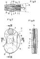
- FIG. 3 there are three clamping zones 9 on the leaf spring 12 in the uppermost leaf spring level, two outer clamping zones 9 with a transition to the upper part and a central clamping zone 9 with a transition to the next lower leaf spring level, in which there is only a central clamping zone 9 on the leaf spring 15.
- three clamping zones 9 can be seen in the lowest leaf spring plane.
- the leaf springs with three clamping zones are stressed here on bending and tension, while the middle leaf spring 15 generates an additional force when bending, when its free end 14 rests on one side and acts as a travel limit when its free end 14 rests on both sides.
- the free ends 14 of the other leaf springs act as additional resistance and as a path limitation.
- the slots 5 are each cut from one side, the generatrix 17 of a slot 5 being at right angles to the generatrix 17 of the neighboring slot 5.
- the slits 5 cut in the opposite medial direction are symmetrical to one another in order not to produce a lateral bend between the upper receiving surface 2 and the lower receiving surface 3 when the pressure is centric.
- the slot width 10 and the leaf spring thickness 11 are selected such that when certain pressure and / or bending loads are exceeded, the slot width 10 on both sides of the leaf springs is reduced to zero at certain locations and path limits occur before the elasticity limit is reached on the leaf springs.
- intervertebral disc bodies depends on the material selected, which must have sufficient strength and elastic behavior.
- the slots 5 can be produced by sawing or spark-erosive wire cutting, with a tangential generatrix 17 resting in the base 16 of the slot.
- a further possibility consists in layering and connecting leaf springs which are provided with spacers corresponding to the slot width 10 in the clamping zones 9.
- Metallurgical joining techniques can be used for joining such a body in metals, while adhesives and binders with a correspondingly high affinity for the base material can be used for plastics and fiber composite materials.
- the structured surface 19, which in the example of FIGS. 1, 2, 3 is a metal grid 23, is excluded from the restrictions with regard to joining, which can be welded to a metallic intervertebral disc body 1 as well as partially enclosed by an intervertebral disc body 1 made of plastic .
- the receiving surface runs in a wedge shape from ventral to dorsal with a wedge angle 18 towards one another.
- a part of the receiving surfaces 2, 3 is convex, so that it can be anchored in intraoperatively produced concave counter surfaces, which are not shown.
- parts of a collar 21 projecting from the neighboring vertebra are shown in FIGS. 7 and 8, which are intended to prevent the intervertebral disk prosthesis from slipping.
- the clamping zones 9 are circular, so that a tangential generatrix 17 is only in the form of a point in the slot base 16 and can be rotated around the center of the circular clamping zone 9.
- round clamping zones 9 consists in a direction-independent introduction of force into the bending springs 7.
- leaf springs 15 are additionally shown, which only have a pronounced location as the clamping zone 9, in that one of the delimiting slots 5 is cut in from one side only. If, in this spring 15, a neighboring spring is pressed against the free end 14, an additional resistance builds up until there is a path limitation on the other side when striking the boundary surface 8 in the slot.
- Intervertebral disc body 1 can be equipped with non-linear characteristics for compression and bending if additional leaf springs come into engagement during the course of the deformation of leaf springs or if additional support points result from the deformation.
- Typical measurement results for compression and for flexion of an intervertebral disc prosthesis are shown in the diagrams in FIGS. 10 and 11.
- FIG. 10 shows the relationship between a compressive force in Newtons acting in axis 4 and the compression of the intervertebral disc body in millimeters.
- Figure 11 shows the bending moment in Newtons Meters for different bending angles in o for bending in the frontal direction and for bending in the lateral direction.
Abstract
Description
- Die Erfindung handelt von einer Bandscheibenprothese, die in ihren äusseren Abmessungen einer natürlichen Bandscheibe nachgeformt ist, die in ihrer Achse zwei benachbarte Wirbel verbindet und die eine obere und eine untere Aufnahmefläche aufweist.
- Die Patentschrift US 4,309,777 zeigt eine Bandscheibenprothese, die aus einer Dose mit einer unteren und einer oberen Hälfte, die unter Kompression von eingelegten Schraubenfedern gegeneinander beweglich sind. Diese Lösung hat den Nachteil, dass die aneinander gleitenden Dosenränder bei Biegebelastungen verklemmen können, dass Abrieb erzeugt wird und dass in der Dose ein eingeschlossenes relativ grosses Leervolumen besteht, welches sich mit Körperflüssigkeit füllen kann.
- Hier schafft die Erfindung Abhilfe. Sie löst die Aufgabe eine einfache Bandscheibenprothese zu schaffen, die die vorher erwähnten Nachteile nicht aufweist. Gemäss der Erfindung wird die Aufgabe dadurch gelöst, dass der Bandscheibenkörper einteilig ist, aus einem festen, elastisch deformierbarem Werkstoff besteht und quer zur Achse parallele und sich teilweise überdeckende Schlitze aufweist, wobei sich benachbarte Schlitze in einem Ueberdeckungsbereich Teile von Blattfedern zur Uebertragung von Kräften von einer Aufnahmefläche zur anderen Aufnahmefläche bilden.
- Die Vorteile der Erfindung sind darin zu sehen, dass die Prothese einfach in ihrer Handhabung ist und dass sie bei Biegebelastung und bei Druckbelastung eine nicht lineare Federcharakteristik besitzt, die in einer Wegbegrenzung endet. Die abhängigen Unteransprüche 2 bis 12 beziehen sich auf vorteilhafte Weiterbildungen der Erfindung.
- Im folgenden wird die Erfindung anhand von Ausführungsbeispielen beschrieben. Es zeigen:
- Figur 1 die Draufsicht auf eine erfindungsgemässe Bandscheibenprothese, die Blattfedern mit drei Einspannzonen aufweist;
- Figur 2 die Seitenansicht eines Schnitts durch die Bandscheibenprothese von Fig. 1;
- Figur 3 die Frontalansicht eines Schnitts durch die Bandscheibenprothese von Fig. 1;
- Figur 4 die Draufsicht auf eine erfindungsgemässe Bandscheibenprothese, die Blattfedern mit zwei Einspannzonen aufweist;
- Figur 5 die Seitenansicht eines Schnitts durch die Bandscheibenprothese von Fig. 4;
- Figur 6 die Frontalansicht eines Schnitts durch die Bandscheibenprothese von Fig. 4;
- Figur 7 die Draufsicht auf eine erfindungsgemässe Bandscheibenprothese, die Blattfedern mit zwei Einspannzonen und Blattfedern mit einer Einspannzone aufweist;
- Figur 8 die Seitenansicht eines Schnitts durch die Bandscheibenprothese von Fig. 7;
- Figur 9 die Frontalansicht eines Schnitts durch die Bandscheibenprothese von Fig. 7;
- Figur 10 die nicht lineare Federcharakteristik bei vertikaler Kompression der Bandscheibenprothese (Druckkraft in Funktion von Auslenkung);
- Figur 11 die nicht lineare Federcharakteristik bei lateraler und bei frontaler Flexion der Bandscheibenprothese (Biegemoment in Funktion von Biegewinkel).
- In den Figuren ist eine Bandscheibenprothese gezeigt, die in ihren äusseren Abmessungen einer natürlichen Bandscheibe nachgeformt ist und zwei benachbarte Wirbel mit ihrer oberen und unteren Aufnahmefläche verbindet. Der Bandscheibenkörper ist einteilig, besteht aus einem festen, elastisch deformierbaren Werkstoff und weist quer zur verbindenden Achse parallele und sich teilweise überdeckende Schlitze auf. Dabei bilden sich benachbarte Schlitze in einem Ueberdeckungsbereich Teile von Blattfedern zur Uebertragung von Kräften von einer Aufnahmefläche zur anderen Aufnahmefläche.
- In einer Ausführung nach den Figuren 1, 2, 3 ist ein Bandscheibenkörper 1 auf seiner oberen Begrenzungsfläche 2 und auf seiner unteren Begrenzungsfläche 3 mit einer strukturierten Oberfläche 19 versehen, die beispielsweise aus einem Gitter besteht. Quer zur vertikalen Achse 4 sind im Bandscheibenkörper 1 Schlitze 5 angebracht, die den Bandscheibenkörper 1 aber nie ganz entzweischneiden. Diese Schlitze 5 sind parallel zueinander, überdecken sich teilweise und bilden mit ihren Begrenzungsflächen 8 - wenn es sich um benachbarte Schlitze 5 handelt - Teile von Blattfedern 7 im Ueberdeckungsbereich 6. Im sich nicht überdeckenden Bereich der benachbarten Schlitze 5 ist die Federwirkung der Blattfedern 7 durch Einspannzonen 9 unterbrochen. Die an der Bandscheibe angreifenden Kräfte werden von einer Blattfederebene zur nächsten Blattfederebene über die Einspannzonen 9 übertragen.
- In Figur 3 sind in der obersten Blattfederebene drei Einspannzonen 9 an der Blattfeder 12, zwei äussere Einspannzonen 9 mit Uebergang zum Oberteil und eine mittlere Einspannzone 9 mit Uebergang zur nächsten tieferen Blattfederebene, in der nur eine mittlere Einspannzone 9 an Blattfeder 15 vorhanden ist. In Figur 2 sind in der untersten Blattfederebene drei Einspannzonen 9 zu sehen. Die Blattfedern mit drei Einspannzonen werden hier auf Biegung und Zug beansprucht, während die mittlere Blattfeder 15 bei Biegung eine Zusatzkraft erzeugt, wenn ihr freies Ende 14 einseitig anliegt und als Wegbegrenzung wirkt, wenn ihr freies Ende 14 beidseitig anliegt. Ebenso wirken die freien Enden 14 der anderen Blattfedern als Zusatzwiderstand und als Wegbegrenzung.
- In einer Ausführung nach den Figuren 4, 5, 6 sind strukturierte Oberflächen 19 mit Spitzen 20 und Blattfedern 13 mit zwei Einspannzonen 9 gezeigt. Die Schlitze 5 sind jeweils von einer Seite her eingeschnitten, wobei die Erzeugende 17 eines Schlitzes 5 im rechten Winkel zu der Erzeugenden 17 des Nachbarschlitzes 5 steht. Die von medial entgegengesetzt eingeschnittenen Schlitze 5 sind abgesehen von den versetzten Ebenen symmetrisch zueinander, um bei zentrischer Druckbelastung keine seitliche Biegung zwischen der oberen Aufnahmefläche 2 und der unteren Aufnahmefläche 3 zu erzeugen. Schlitzbreite 10 und Blattfederdicke 11 sind so gewählt, dass beim Ueberschreiten bestimmter Druck- und/oder Biegebelastungen die Schlitzbreite 10 beidseitig der Blattfedern an bestimmten Orten auf Null reduziert wird und Wegbegrenzungen entstehen, bevor an den Blattfedern die Elastizitätsgrenze erreicht ist.
- Die Herstellung solcher Bandscheibenkörper hängt vom gewählten Werkstoff ab, der genügend Festigkeit und ein elastisches Verhalten aufweisen muss. Bei Metallen wie z.B. Titanlegierungen können die Schlitze 5 durch Sägen oder funkenerosives Drahtschneiden erzeugt werden, wobei eine tangentiale Erzeugende 17 im Grund 16 des Schlitzes anliegt. Eine weitere Möglichkeit besteht im Schichten und Verbinden von Blattfedern, die in den Einspannzonen 9 der Schlitzbreite 10 entsprechende Distanzierstücke erhalten. Zum Fügen eines solchen Körpers kommen bei Metallen metallurgische Verbindungstechniken in Frage, während bei Kunststoffen und Faserverbundwerkstoffen Kleber und Binder in Frage kommen, die eine entsprechend hohe Affinität zum Grundmaterial aufweisen. Von den Einschränkungen bezüglich fügen ist die strukturierte Oberfläche 19 ausgenommen, die im Beispiel der Figuren 1, 2, 3 ein Metallgitternetz 23 ist, das sowohl mit einem metallischen Bandscheibenkörper 1 verschweisst sein kann, als auch von einem Bandscheibenkörper 1 aus Kunststoff teilweise umschlossen sein kann.
- In einer Ausführung nach den Figuren 7, 8, 9 laufen die Aufnahmefläche von ventral nach dorsal keilförmig mit einem Keilwinkel 18 aufeinander zu. Ein Teil der Aufnahmeflächen 2, 3 ist konvex ausgeführt, damit er in intraoperativ erzeugten konkaven Gegenflächen, die nicht gezeigt sind, verankert werden kann. Als zusätzliche Verankerungshilfe sind in Figuren 7, 8 Teile eines zum Nachbarwirbel vorstehenden Kragens 21 gezeigt, die ein Verrutschen der Bandscheibenprothese verhindern sollen. Die Einspannzonen 9 sind kreisförmig ausgeführt, sodass eine tangentiale Erzeugende 17 nur noch punktförmig im Schlitzgrund 16 anliegt und um den Mittelpunkt der kreisförmigen Einspannzone 9 rotiert werden kann. Der Vorteil von runden Einspannzonen 9 besteht in einer richtungsunabhängigen Krafteinleitung in die Biegefedern 7. In Figur 8 sind zusätzlich Blattfedern 15 gezeigt, die als Einspannzone 9 nur einen ausgeprägten Ort besitzen, indem einer der begrenzenden Schlitze 5 nur von einer Seite eingeschnitten ist. Wird bei dieser Feder 15 eine Nachbarfeder gegen das freie Ende 14 gepresst, baut sich ein zusätzlicher Widerstand auf bis beim Anschlagen an der Begrenzungsfläche 8 im Schlitz auf der anderen Seite eine Wegbegrenzung entsteht.
- Bandscheibenkörper 1, können mit nicht linearen Charakteristiken für Kompression und Biegung ausgestattet werden, wenn im Verlauf der Deformation von Blattfedern zusätzliche Blattfedern in Eingriff kommen oder zusätzliche Abstützpunkte durch die Deformation entstehen. Typische Messresultate für Kompression und für Flexion einer Bandscheibenprothese sind in den Diagrammen der Figuren 10 und 11 gezeigt. Figur 10 zeigt die Abhängigkeit zwischen einer in Achse 4 angreifenden Druckkraft in Newton und der Kompression des Bandscheibenkörpers in Millimeter. Figur 11 zeigt das Biegemoment in Newton Meter für verschiedene Biegewinkel in o bei Biegung in frontaler Richtung und bei Biegung in seitlicher Richtung.
Claims (12)
- Bandscheibenprothese, die in ihren äusseren Abmessungen einer natürlichen Bandscheibe nachgeformt ist, die in ihrer Achse (4) zwei benachbarte Wirbel verbindet und die eine obere und eine untere Aufnahmefläche (2, 3) aufweist, dadurch gekennzeichnet, dass der Bandscheibenkörper (1) einteilig ist, aus einem festen, elastisch deformierbarem Werkstoff besteht und quer zur Achse (4) parallele und sich teilweise überdeckende Schlitze (5) aufweist, wobei sich benachbarte Schlitze (5) in einem Ueberdeckungsbereich (6) Teile von Blattfedern (7, 12, 13, 15) zur Uebertragung von Kräften von der oberen Aufnahmefläche (2) zur unteren Aufnahmefläche (3) bilden.
- Bandscheibenprothese entsprechend Anspruch 1, dadurch gekennzeichnet, dass Schlitzbreite (10) und Blattfederdicke (11) so gewählt sind, dass beim Ueberschreiten bestimmter Druck- und/oder Biegebelastungen die Schlitzbreite (10) an bestimmten Orten auf Null reduziert wird und Wegbegrenzungen entstehen bevor in den Blattfedern die Elastizitätsgrenze erreicht ist.
- Bandscheibenprothese nach einem der Ansprüche 1 oder 2, dadurch gekennzeichnet, dass der feste, elastisch deformierbare Werkstoff Metall ist.
- Bandscheibenprothese nach einem der Ansprüche 1 bis 3, dadurch gekennzeichnet, dass die Blattfeder (12) einer Ebene an drei ausgeprägten Orten eingespannt ist.
- Bandscheibenprothese nach einem der Ansprüche 1 bis 3, dadurch gekennzeichnet, dass die Blattfeder (13) einer Ebene an zwei ausgeprägten Orten eingespannt ist.
- Bandscheibenprothese nach einem der Ansprüche 1 bis 3, dadurch gekennzeichnet, dass die Blattfeder (15) einer Ebene an einem ausgeprägten Ort eingespannt ist.
- Bandscheibenprothese nach einem der Ansprüche 1 bis 6, dadurch gekennzeichnet, dass die freien Enden (14) von Blattfedern (7) bei einseitiger Reduktion der Schlitzbreite (10) auf Null als Biegefedern wirken und bei beidseitiger Reduktion der Schlitzbreite (10) auf Null als Wegbegrenzung wirken.
- Bandscheibenprothese nach einem der Ansprüche 1 bis 6, dadurch gekennzeichnet, dass Schlitze (5) in ihrem Grund (16) bezüglich Herstellung durch eine tangentiale Erzeugende (17) erreichbar sind.
- Bandscheibenprothese nach einem der Ansprüche 1 bis 8, dadurch gekennzeichnet, dass die Aufnahmeflächen (2, 3) von ventral nach dorsal keilförmig aufeinander zulaufen.
- Bandscheibenprothese nach einem der Ansprüche 1 bis 9, dadurch gekennzeichnet, dass die Aufnahmeflächen (2, 3) eine Strukturierung (19) für die Primärverankerung an den angrenzenden Wirbeln aufweisen.
- Bandscheibenprothese nach einem der Ansprüche 1 bis 8, dadurch gekennzeichnet, dass mindestens Teile der Aufnahmeflächen (2, 3) konvex ausgeführt sind, um sich in intraoperativ erzeugten konkaven Gegenflächen der angrenzenden Wirbel zu zentrieren und zu verankern.
- Bandscheibenprothese nach einem der Ansprüche 1 bis 9, dadurch gekennzeichnet, dass die Aufnahmeflächen (2, 3) Teile eines zum Nachbarwirbel vorstehenden Kragens (21) aufweisen, um ein Verrutschen der Bandscheibenprothese zu verhindern.
Applications Claiming Priority (2)
| Application Number | Priority Date | Filing Date | Title |
|---|---|---|---|
| CH255291 | 1991-08-30 | ||
| CH2552/91 | 1991-08-30 |
Publications (2)
| Publication Number | Publication Date |
|---|---|
| EP0538183A1 true EP0538183A1 (de) | 1993-04-21 |
| EP0538183B1 EP0538183B1 (de) | 1996-01-31 |
Family
ID=4236369
Family Applications (1)
| Application Number | Title | Priority Date | Filing Date |
|---|---|---|---|
| EP92810584A Expired - Lifetime EP0538183B1 (de) | 1991-08-30 | 1992-07-31 | Bandscheibenprothese |
Country Status (5)
| Country | Link |
|---|---|
| US (1) | US5320644A (de) |
| EP (1) | EP0538183B1 (de) |
| AT (1) | ATE133555T1 (de) |
| DE (1) | DE59205228D1 (de) |
| ES (1) | ES2082430T3 (de) |
Cited By (28)
| Publication number | Priority date | Publication date | Assignee | Title |
|---|---|---|---|---|
| WO1994026213A1 (de) * | 1993-05-11 | 1994-11-24 | Plus Endoprothetik Ag | Wirbelkörperimplantat |
| WO1995001763A1 (de) * | 1993-07-09 | 1995-01-19 | Lutz Biedermann | Platzhalter, insbesondere für eine bandscheibe |
| FR2717370A1 (fr) * | 1994-03-18 | 1995-09-22 | Moreau Patrice | Prothèse intervertébrale de stabilisation. |
| EP0677277A2 (de) * | 1994-03-18 | 1995-10-18 | Patrice Moreau | Wirbelprothese |
| EP0716841A1 (de) * | 1994-12-16 | 1996-06-19 | Tornier Sa | Elastische Bandscheibenprothese |
| FR2730405A1 (fr) * | 1995-02-10 | 1996-08-14 | Moreau Patrice | Prothese souple intervertebrale |
| FR2734148A1 (fr) * | 1995-05-15 | 1996-11-22 | Biomat | Prothese intervertebrale |
| FR2744627A1 (fr) * | 1996-02-09 | 1997-08-14 | Bouvet Jean Claude | Prothese destinee a restaurer une articulation entre deux os trouvant une application avantageuse comme prothese de hanche et prothese intervertebrale |
| WO1999020209A1 (en) * | 1997-10-17 | 1999-04-29 | Depuy Acromed, Inc. | Spinal disc prosthesis |
| WO1999022675A1 (en) * | 1997-10-31 | 1999-05-14 | Depuy Acromed, Inc. | Spinal disc prosthesis |
| WO2000023014A1 (en) * | 1998-10-20 | 2000-04-27 | Synthes Ag Chur | Strain regulating fusion cage for spinal fusion surgery |
| US6113638A (en) * | 1999-02-26 | 2000-09-05 | Williams; Lytton A. | Method and apparatus for intervertebral implant anchorage |
| US6143033A (en) * | 1998-01-30 | 2000-11-07 | Synthes (Usa) | Allogenic intervertebral implant |
| US6258125B1 (en) | 1998-08-03 | 2001-07-10 | Synthes (U.S.A.) | Intervertebral allograft spacer |
| DE19804022C2 (de) * | 1997-11-12 | 2002-09-19 | Schaefer Micomed Gmbh | Zwischenwirbelimplantat |
| US6511509B1 (en) | 1997-10-20 | 2003-01-28 | Lifenet | Textured bone allograft, method of making and using same |
| US6520993B2 (en) | 2000-12-29 | 2003-02-18 | Depuy Acromed, Inc. | Spinal implant |
| USRE38614E1 (en) * | 1998-01-30 | 2004-10-05 | Synthes (U.S.A.) | Intervertebral allograft spacer |
| WO2005094733A1 (de) * | 2004-04-02 | 2005-10-13 | Synthes Gmbh | Bandscheibenprothese oder künstlicher wirbelkörper |
| US6964686B2 (en) | 1999-05-17 | 2005-11-15 | Vanderbilt University | Intervertebral disc replacement prosthesis |
| WO2006013603A2 (en) * | 2004-08-05 | 2006-02-09 | Biomedica S.R.L. | Bone spacer |
| EP1779814A1 (de) | 2005-10-26 | 2007-05-02 | BIEDERMANN MOTECH GmbH | Implantat mit einstückigem Drehgelenk |
| US7331994B2 (en) | 1999-05-17 | 2008-02-19 | Vanderbilt University | Intervertebral disc replacement prosthesis |
| WO2008106912A1 (de) * | 2007-03-07 | 2008-09-12 | Ulrich Gmbh & Co. Kg | Zwischenwirbelimplantat mit elastischem bauteil |
| EP2108340A1 (de) * | 2001-03-23 | 2009-10-14 | Howmedica Osteonics Corp. | Modularimplantat zur Verwendung einer benachbarten Knochenstruktur |
| US8696749B2 (en) | 2002-04-25 | 2014-04-15 | Blackstone Medical, Inc. | Artificial intervertebral disc |
| US9597198B2 (en) | 2006-02-15 | 2017-03-21 | Ldr Medical | Transforaminal intersomatic cage for an intervertebral fusion graft and an instrument for implanting the cage |
| CN110433015A (zh) * | 2018-05-02 | 2019-11-12 | 曾昌和 | 一种骨质疏松脊椎体弹性椎间植入装置 |
Families Citing this family (249)
| Publication number | Priority date | Publication date | Assignee | Title |
|---|---|---|---|---|
| US5423816A (en) * | 1993-07-29 | 1995-06-13 | Lin; Chih I. | Intervertebral locking device |
| US5425772A (en) * | 1993-09-20 | 1995-06-20 | Brantigan; John W. | Prosthetic implant for intervertebral spinal fusion |
| US5824093A (en) * | 1994-10-17 | 1998-10-20 | Raymedica, Inc. | Prosthetic spinal disc nucleus |
| US5674296A (en) | 1994-11-14 | 1997-10-07 | Spinal Dynamics Corporation | Human spinal disc prosthesis |
| US5865845A (en) * | 1996-03-05 | 1999-02-02 | Thalgott; John S. | Prosthetic intervertebral disc |
| US6111164A (en) * | 1996-06-21 | 2000-08-29 | Musculoskeletal Transplant Foundation | Bone graft insert |
| US5728159A (en) * | 1997-01-02 | 1998-03-17 | Musculoskeletal Transplant Foundation | Serrated bone graft |
| US6022376A (en) * | 1997-06-06 | 2000-02-08 | Raymedica, Inc. | Percutaneous prosthetic spinal disc nucleus and method of manufacture |
| US20010016773A1 (en) * | 1998-10-15 | 2001-08-23 | Hassan Serhan | Spinal disc |
| US6482233B1 (en) | 1998-01-29 | 2002-11-19 | Synthes(U.S.A.) | Prosthetic interbody spacer |
| US6986788B2 (en) | 1998-01-30 | 2006-01-17 | Synthes (U.S.A.) | Intervertebral allograft spacer |
| DE29806830U1 (de) * | 1998-04-16 | 1998-07-02 | Aesculap Ag & Co Kg | Zwischenwirbelfusionsimplantat |
| US6241769B1 (en) | 1998-05-06 | 2001-06-05 | Cortek, Inc. | Implant for spinal fusion |
| US6296664B1 (en) * | 1998-06-17 | 2001-10-02 | Surgical Dynamics, Inc. | Artificial intervertebral disc |
| US6136031A (en) * | 1998-06-17 | 2000-10-24 | Surgical Dynamics, Inc. | Artificial intervertebral disc |
| AU748746B2 (en) | 1998-07-22 | 2002-06-13 | Spinal Dynamics Corporation | Threaded cylindrical multidiscoid single or multiple array disc prosthesis |
| CA2342633C (en) * | 1998-09-04 | 2007-11-13 | Spinal Dynamics Corporation | Peanut spectacle multi discoid thoraco-lumbar disc prosthesis |
| US20070038231A1 (en) * | 1999-05-28 | 2007-02-15 | Ferree Bret A | Methods and apparatus for treating disc herniation and preventing the extrusion of interbody bone graft |
| US6969404B2 (en) * | 1999-10-08 | 2005-11-29 | Ferree Bret A | Annulus fibrosis augmentation methods and apparatus |
| US6419704B1 (en) | 1999-10-08 | 2002-07-16 | Bret Ferree | Artificial intervertebral disc replacement methods and apparatus |
| US7273497B2 (en) * | 1999-05-28 | 2007-09-25 | Anova Corp. | Methods for treating a defect in the annulus fibrosis |
| US20060247665A1 (en) * | 1999-05-28 | 2006-11-02 | Ferree Bret A | Methods and apparatus for treating disc herniation and preventing the extrusion of interbody bone graft |
| US6520996B1 (en) | 1999-06-04 | 2003-02-18 | Depuy Acromed, Incorporated | Orthopedic implant |
| FR2797179B1 (fr) * | 1999-08-03 | 2002-03-08 | Michel Gau | Prothese nucleaire intervertebrale et son procede chirurgical d'implantation |
| US7435260B2 (en) * | 1999-08-13 | 2008-10-14 | Ferree Bret A | Use of morphogenetic proteins to treat human disc disease |
| US6685695B2 (en) * | 1999-08-13 | 2004-02-03 | Bret A. Ferree | Method and apparatus for providing nutrition to intervertebral disc tissue |
| US6755863B2 (en) * | 1999-10-08 | 2004-06-29 | Bret A. Ferree | Rotator cuff repair using engineered tissues |
| US6793677B2 (en) * | 1999-08-13 | 2004-09-21 | Bret A. Ferree | Method of providing cells and other biologic materials for transplantation |
| US7201776B2 (en) * | 1999-10-08 | 2007-04-10 | Ferree Bret A | Artificial intervertebral disc replacements with endplates |
| US6454804B1 (en) | 1999-10-08 | 2002-09-24 | Bret A. Ferree | Engineered tissue annulus fibrosis augmentation methods and apparatus |
| EP1624832A4 (de) | 1999-08-18 | 2008-12-24 | Intrinsic Therapeutics Inc | Vorrichtungen und verfahren zur augmentierung eines wirbelscheiben-nukleus |
| US7972337B2 (en) | 2005-12-28 | 2011-07-05 | Intrinsic Therapeutics, Inc. | Devices and methods for bone anchoring |
| US7507243B2 (en) * | 1999-08-18 | 2009-03-24 | Gregory Lambrecht | Devices and method for augmenting a vertebral disc |
| US7094258B2 (en) | 1999-08-18 | 2006-08-22 | Intrinsic Therapeutics, Inc. | Methods of reinforcing an annulus fibrosis |
| US8323341B2 (en) | 2007-09-07 | 2012-12-04 | Intrinsic Therapeutics, Inc. | Impaction grafting for vertebral fusion |
| US7553329B2 (en) | 1999-08-18 | 2009-06-30 | Intrinsic Therapeutics, Inc. | Stabilized intervertebral disc barrier |
| US7998213B2 (en) | 1999-08-18 | 2011-08-16 | Intrinsic Therapeutics, Inc. | Intervertebral disc herniation repair |
| US6425919B1 (en) | 1999-08-18 | 2002-07-30 | Intrinsic Orthopedics, Inc. | Devices and methods of vertebral disc augmentation |
| US6936072B2 (en) * | 1999-08-18 | 2005-08-30 | Intrinsic Therapeutics, Inc. | Encapsulated intervertebral disc prosthesis and methods of manufacture |
| JP4247519B2 (ja) | 1999-08-18 | 2009-04-02 | イントリンジック セラピューティックス インコーポレイテッド | 髄核オーグメンテーションおよび保定のための装置および方法 |
| US7717961B2 (en) | 1999-08-18 | 2010-05-18 | Intrinsic Therapeutics, Inc. | Apparatus delivery in an intervertebral disc |
| US6080158A (en) * | 1999-08-23 | 2000-06-27 | Lin; Chih-I | Intervertebral fusion device |
| US20030004574A1 (en) * | 1999-10-08 | 2003-01-02 | Ferree Bret A. | Disc and annulus augmentation using biologic tissue |
| US7060100B2 (en) * | 1999-10-08 | 2006-06-13 | Ferree Bret A | Artificial disc and joint replacements with modular cushioning components |
| US6648920B2 (en) * | 1999-10-08 | 2003-11-18 | Bret A. Ferree | Natural and synthetic supplements to engineered annulus and disc tissues |
| US7201774B2 (en) * | 1999-10-08 | 2007-04-10 | Ferree Bret A | Artificial intervertebral disc replacements incorporating reinforced wall sections |
| US20030026788A1 (en) * | 1999-10-08 | 2003-02-06 | Ferree Bret A. | Use of extracellular matrix tissue to preserve cultured cell phenotype |
| US20040186573A1 (en) * | 1999-10-08 | 2004-09-23 | Ferree Bret A. | Annulus fibrosis augmentation methods and apparatus |
| US6645247B2 (en) * | 1999-10-08 | 2003-11-11 | Bret A. Ferree | Supplementing engineered annulus tissues with autograft of allograft tendons |
| US6648919B2 (en) * | 1999-10-14 | 2003-11-18 | Bret A. Ferree | Transplantation of engineered meniscus tissue to the intervertebral disc |
| US7935147B2 (en) | 1999-10-20 | 2011-05-03 | Anulex Technologies, Inc. | Method and apparatus for enhanced delivery of treatment device to the intervertebral disc annulus |
| US8128698B2 (en) | 1999-10-20 | 2012-03-06 | Anulex Technologies, Inc. | Method and apparatus for the treatment of the intervertebral disc annulus |
| US8632590B2 (en) | 1999-10-20 | 2014-01-21 | Anulex Technologies, Inc. | Apparatus and methods for the treatment of the intervertebral disc |
| US6592625B2 (en) | 1999-10-20 | 2003-07-15 | Anulex Technologies, Inc. | Spinal disc annulus reconstruction method and spinal disc annulus stent |
| US7615076B2 (en) | 1999-10-20 | 2009-11-10 | Anulex Technologies, Inc. | Method and apparatus for the treatment of the intervertebral disc annulus |
| US7951201B2 (en) | 1999-10-20 | 2011-05-31 | Anulex Technologies, Inc. | Method and apparatus for the treatment of the intervertebral disc annulus |
| US7004970B2 (en) | 1999-10-20 | 2006-02-28 | Anulex Technologies, Inc. | Methods and devices for spinal disc annulus reconstruction and repair |
| US7052516B2 (en) | 1999-10-20 | 2006-05-30 | Anulex Technologies, Inc. | Spinal disc annulus reconstruction method and deformable spinal disc annulus stent |
| US6592624B1 (en) * | 1999-11-24 | 2003-07-15 | Depuy Acromed, Inc. | Prosthetic implant element |
| US6805695B2 (en) | 2000-04-04 | 2004-10-19 | Spinalabs, Llc | Devices and methods for annular repair of intervertebral discs |
| US20020130112A1 (en) * | 2000-06-05 | 2002-09-19 | Mark Manasas | Orthopedic implant and method of making metal articles |
| USD494274S1 (en) | 2000-06-12 | 2004-08-10 | Ortho Development Corporation | Implant |
| US6579318B2 (en) | 2000-06-12 | 2003-06-17 | Ortho Development Corporation | Intervertebral spacer |
| FR2812185B1 (fr) | 2000-07-25 | 2003-02-28 | Spine Next Sa | Piece de liaison semi-rigide pour la stabilisation du rachis |
| US6610093B1 (en) | 2000-07-28 | 2003-08-26 | Perumala Corporation | Method and apparatus for stabilizing adjacent vertebrae |
| CA2429246C (en) * | 2000-08-08 | 2011-06-07 | Vincent Bryan | Implantable joint prosthesis |
| US7125380B2 (en) * | 2000-08-08 | 2006-10-24 | Warsaw Orthopedic, Inc. | Clamping apparatus and methods |
| US6949105B2 (en) | 2000-08-08 | 2005-09-27 | Sdgi Holdings, Inc. | Method and apparatus for stereotactic implantation |
| US7601174B2 (en) * | 2000-08-08 | 2009-10-13 | Warsaw Orthopedic, Inc. | Wear-resistant endoprosthetic devices |
| US7226480B2 (en) * | 2000-08-15 | 2007-06-05 | Depuy Spine, Inc. | Disc prosthesis |
| US6458159B1 (en) * | 2000-08-15 | 2002-10-01 | John S. Thalgott | Disc prosthesis |
| US6824565B2 (en) | 2000-09-08 | 2004-11-30 | Nabil L. Muhanna | System and methods for inserting a vertebral spacer |
| US8628575B2 (en) | 2000-08-29 | 2014-01-14 | Nabil L. Muhanna | Vertebral body replacement and method of use |
| US20020026244A1 (en) * | 2000-08-30 | 2002-02-28 | Trieu Hai H. | Intervertebral disc nucleus implants and methods |
| US6620196B1 (en) | 2000-08-30 | 2003-09-16 | Sdgi Holdings, Inc. | Intervertebral disc nucleus implants and methods |
| US20050154463A1 (en) * | 2000-08-30 | 2005-07-14 | Trieu Hal H. | Spinal nucleus replacement implants and methods |
| ES2303972T3 (es) | 2000-08-30 | 2008-09-01 | Warsaw Orthopedic, Inc. | Implantes de disco intervertebral. |
| US7503936B2 (en) * | 2000-08-30 | 2009-03-17 | Warsaw Orthopedic, Inc. | Methods for forming and retaining intervertebral disc implants |
| US7204851B2 (en) * | 2000-08-30 | 2007-04-17 | Sdgi Holdings, Inc. | Method and apparatus for delivering an intervertebral disc implant |
| US6743257B2 (en) * | 2000-12-19 | 2004-06-01 | Cortek, Inc. | Dynamic implanted intervertebral spacer |
| US6562045B2 (en) | 2001-02-13 | 2003-05-13 | Sdgi Holdings, Inc. | Machining apparatus |
| US7179295B2 (en) * | 2001-10-05 | 2007-02-20 | Nebojsa Kovacevic | Prosthetic shock absorber |
| US7025787B2 (en) * | 2001-11-26 | 2006-04-11 | Sdgi Holdings, Inc. | Implantable joint prosthesis and associated instrumentation |
| US20060129242A1 (en) * | 2001-12-28 | 2006-06-15 | Brian Bergeron | Pseudo arthrosis device |
| US6736850B2 (en) * | 2001-12-28 | 2004-05-18 | Spinal Concepts, Inc. | Vertebral pseudo arthrosis device and method |
| US7708776B1 (en) | 2002-01-16 | 2010-05-04 | Nuvasive, Inc. | Intervertebral disk replacement system and methods |
| US20060004454A1 (en) * | 2002-04-24 | 2006-01-05 | Ferree Bret A | Assembled disc spacers |
| US20040030391A1 (en) * | 2002-04-24 | 2004-02-12 | Bret Ferree | Artificial intervertebral disc spacers |
| US8388684B2 (en) | 2002-05-23 | 2013-03-05 | Pioneer Signal Technology, Inc. | Artificial disc device |
| US7001433B2 (en) | 2002-05-23 | 2006-02-21 | Pioneer Laboratories, Inc. | Artificial intervertebral disc device |
| JP4256345B2 (ja) * | 2002-08-15 | 2009-04-22 | コップス,ジャスティン,ケー. | 椎間板インプラント |
| JP4456481B2 (ja) | 2002-08-15 | 2010-04-28 | ガーバー,デイヴィッド | 制御された人工椎間板インプラント |
| US7101400B2 (en) * | 2002-08-19 | 2006-09-05 | Jeffery Thramann | Shaped memory artificial disc and methods of engrafting the same |
| US20060293753A1 (en) * | 2002-08-19 | 2006-12-28 | Lanx, Llc | Corrective artificial disc |
| US6966929B2 (en) | 2002-10-29 | 2005-11-22 | St. Francis Medical Technologies, Inc. | Artificial vertebral disk replacement implant with a spacer |
| US7083649B2 (en) * | 2002-10-29 | 2006-08-01 | St. Francis Medical Technologies, Inc. | Artificial vertebral disk replacement implant with translating pivot point |
| US7497859B2 (en) | 2002-10-29 | 2009-03-03 | Kyphon Sarl | Tools for implanting an artificial vertebral disk |
| US7273496B2 (en) * | 2002-10-29 | 2007-09-25 | St. Francis Medical Technologies, Inc. | Artificial vertebral disk replacement implant with crossbar spacer and method |
| US20040133278A1 (en) * | 2002-10-31 | 2004-07-08 | Marino James F. | Spinal disc implant |
| EP2329778A3 (de) | 2003-01-31 | 2012-06-20 | Spinalmotion, Inc. | Anzeige für die Wirbelsäulenmittellinie |
| WO2004066884A1 (en) | 2003-01-31 | 2004-08-12 | Spinalmotion, Inc. | Intervertebral prosthesis placement instrument |
| US20040158254A1 (en) * | 2003-02-12 | 2004-08-12 | Sdgi Holdings, Inc. | Instrument and method for milling a path into bone |
| WO2004089240A2 (en) * | 2003-04-04 | 2004-10-21 | Theken Disc, Llc | Artificial disc prosthesis |
| US7575599B2 (en) | 2004-07-30 | 2009-08-18 | Spinalmotion, Inc. | Intervertebral prosthetic disc with metallic core |
| US10052211B2 (en) | 2003-05-27 | 2018-08-21 | Simplify Medical Pty Ltd. | Prosthetic disc for intervertebral insertion |
| US20090076614A1 (en) * | 2007-09-17 | 2009-03-19 | Spinalmotion, Inc. | Intervertebral Prosthetic Disc with Shock Absorption Core |
| WO2004105638A2 (en) | 2003-05-27 | 2004-12-09 | Spinalmotion, Inc. | Prosthetic disc for intervertebral insertion |
| US7537612B2 (en) * | 2003-06-20 | 2009-05-26 | Warsaw Orthopedic, Inc. | Lumbar composite nucleus |
| ATE499910T1 (de) | 2003-06-20 | 2011-03-15 | Intrinsic Therapeutics Inc | Vorrichtung zur abgabe eines implantats durch einen ringförmigen defekt in einer bandscheibe |
| US20040260300A1 (en) | 2003-06-20 | 2004-12-23 | Bogomir Gorensek | Method of delivering an implant through an annular defect in an intervertebral disc |
| US20050015150A1 (en) * | 2003-07-17 | 2005-01-20 | Lee Casey K. | Intervertebral disk and nucleus prosthesis |
| US7909869B2 (en) | 2003-08-05 | 2011-03-22 | Flexuspine, Inc. | Artificial spinal unit assemblies |
| US7753958B2 (en) | 2003-08-05 | 2010-07-13 | Gordon Charles R | Expandable intervertebral implant |
| US7799082B2 (en) * | 2003-08-05 | 2010-09-21 | Flexuspine, Inc. | Artificial functional spinal unit system and method for use |
| DE10348329B3 (de) * | 2003-10-17 | 2005-02-17 | Biedermann Motech Gmbh | Stabförmiges Element für die Anwendung in der Wirbelsäulen- oder Unfallchirurgie,Stabilisierungseinrichtung mit einem solchen stabförmigen Element und Herstellungsverfahren für das stabförmige Element |
| DE102004021861A1 (de) * | 2004-05-04 | 2005-11-24 | Biedermann Motech Gmbh | Flexibler Platzhalter |
| WO2005039454A2 (en) * | 2003-10-17 | 2005-05-06 | Biedermann Motech Gmbh | Flexible implant |
| US9445916B2 (en) | 2003-10-22 | 2016-09-20 | Pioneer Surgical Technology, Inc. | Joint arthroplasty devices having articulating members |
| US7320707B2 (en) | 2003-11-05 | 2008-01-22 | St. Francis Medical Technologies, Inc. | Method of laterally inserting an artificial vertebral disk replacement implant with crossbar spacer |
| US8632570B2 (en) * | 2003-11-07 | 2014-01-21 | Biedermann Technologies Gmbh & Co. Kg | Stabilization device for bones comprising a spring element and manufacturing method for said spring element |
| US20050149192A1 (en) * | 2003-11-20 | 2005-07-07 | St. Francis Medical Technologies, Inc. | Intervertebral body fusion cage with keels and implantation method |
| US7837732B2 (en) * | 2003-11-20 | 2010-11-23 | Warsaw Orthopedic, Inc. | Intervertebral body fusion cage with keels and implantation methods |
| US7691146B2 (en) | 2003-11-21 | 2010-04-06 | Kyphon Sarl | Method of laterally inserting an artificial vertebral disk replacement implant with curved spacer |
| US20050154462A1 (en) | 2003-12-02 | 2005-07-14 | St. Francis Medical Technologies, Inc. | Laterally insertable artificial vertebral disk replacement implant with translating pivot point |
| US20050209603A1 (en) | 2003-12-02 | 2005-09-22 | St. Francis Medical Technologies, Inc. | Method for remediation of intervertebral disks |
| US7217291B2 (en) * | 2003-12-08 | 2007-05-15 | St. Francis Medical Technologies, Inc. | System and method for replacing degenerated spinal disks |
| US7695517B2 (en) * | 2003-12-10 | 2010-04-13 | Axiomed Spine Corporation | Apparatus for replacing a damaged spinal disc |
| US20050165487A1 (en) * | 2004-01-28 | 2005-07-28 | Muhanna Nabil L. | Artificial intervertebral disc |
| US7083651B2 (en) * | 2004-03-03 | 2006-08-01 | Joint Synergy, Llc | Spinal implant |
| US7115144B2 (en) | 2004-03-02 | 2006-10-03 | Joint Synergy, Llc | Spinal implant |
| US7491239B2 (en) | 2005-02-23 | 2009-02-17 | Joint Synergy, Llc | Interior insert ball and dual socket joint |
| US7195644B2 (en) * | 2004-03-02 | 2007-03-27 | Joint Synergy, Llc | Ball and dual socket joint |
| US20050222683A1 (en) * | 2004-03-31 | 2005-10-06 | Sdgi Holdings | Shape memory alloy disc replacement device |
| US7887587B2 (en) * | 2004-06-04 | 2011-02-15 | Synthes Usa, Llc | Soft tissue spacer |
| US8172904B2 (en) * | 2004-06-30 | 2012-05-08 | Synergy Disc Replacement, Inc. | Artificial spinal disc |
| US9237958B2 (en) * | 2004-06-30 | 2016-01-19 | Synergy Disc Replacement Inc. | Joint prostheses |
| EP1773256B1 (de) * | 2004-06-30 | 2019-11-27 | Synergy Disc Replacement Inc. | Künstliche bandscheibe |
| US7585326B2 (en) | 2004-08-06 | 2009-09-08 | Spinalmotion, Inc. | Methods and apparatus for intervertebral disc prosthesis insertion |
| US7303074B2 (en) * | 2004-09-22 | 2007-12-04 | Dombrowski Trudy M | Foldable organizer device |
| US20080004704A1 (en) * | 2004-09-23 | 2008-01-03 | Katz Akiva R | Inter-Vertebral Disc Prosthesis |
| US7575600B2 (en) | 2004-09-29 | 2009-08-18 | Kyphon Sarl | Artificial vertebral disk replacement implant with translating articulation contact surface and method |
| US7481840B2 (en) | 2004-09-29 | 2009-01-27 | Kyphon Sarl | Multi-piece artificial spinal disk replacement device with selectably positioning articulating element |
| US20060089719A1 (en) * | 2004-10-21 | 2006-04-27 | Trieu Hai H | In situ formation of intervertebral disc implants |
| ES2387194T3 (es) * | 2005-01-19 | 2012-09-17 | Nexgen Spine, Inc. | Fijación de elastómero a estructuras rígidas |
| KR20070115886A (ko) * | 2005-01-19 | 2007-12-06 | 넥스젠 스파인 인코포레이티드 | 엘라스토머 추간판 인공삽입물 |
| US8083797B2 (en) | 2005-02-04 | 2011-12-27 | Spinalmotion, Inc. | Intervertebral prosthetic disc with shock absorption |
| US7578847B2 (en) * | 2005-03-03 | 2009-08-25 | Cervical Xpand, Llc | Posterior lumbar intervertebral stabilizer |
| US7799080B2 (en) * | 2005-04-22 | 2010-09-21 | Doty Keith L | Spinal disc prosthesis and methods of use |
| US7361192B2 (en) * | 2005-04-22 | 2008-04-22 | Doty Keith L | Spinal disc prosthesis and methods of use |
| US20060276900A1 (en) * | 2005-06-01 | 2006-12-07 | Carpenter Clyde T | Anatomic total disc replacement |
| US20070016301A1 (en) * | 2005-07-14 | 2007-01-18 | Medical Device Concepts Llc. | Multi-axial interbody spacer device |
| US8328851B2 (en) | 2005-07-28 | 2012-12-11 | Nuvasive, Inc. | Total disc replacement system and related methods |
| EP1757243B1 (de) | 2005-08-24 | 2008-05-28 | BIEDERMANN MOTECH GmbH | Stabförmiges Element für die Anwendung in der Wirbelsäulen- oder Unfallchirurgie und Stabilisierungseinrichtung mit einem solchen Element |
| US20070088439A1 (en) * | 2005-10-13 | 2007-04-19 | Jeffery Thramann | Artificial disc with endplates having cages to promote bone fusion |
| CA2627345A1 (en) | 2005-10-24 | 2007-05-03 | Nexgen Spine, Inc. | Intervertebral disc replacement and associated instrumentation |
| US8753399B2 (en) * | 2005-11-28 | 2014-06-17 | Stryker Spine | Dynamic interbody device |
| WO2007075411A2 (en) * | 2005-12-16 | 2007-07-05 | Thomas Haider Patents, A Limited Liability Company | An intervertebral prosthesis for supporting adjacent vertebral bodies enabling the creation of soft fusion and method |
| US20070179618A1 (en) * | 2006-01-31 | 2007-08-02 | Sdgi Holdings, Inc. | Intervertebral prosthetic disc |
| US20070179615A1 (en) * | 2006-01-31 | 2007-08-02 | Sdgi Holdings, Inc. | Intervertebral prosthetic disc |
| US8118869B2 (en) | 2006-03-08 | 2012-02-21 | Flexuspine, Inc. | Dynamic interbody device |
| US20070225806A1 (en) * | 2006-03-24 | 2007-09-27 | Sdgi Holdings, Inc. | Arthroplasty device |
| US8734519B2 (en) | 2006-04-12 | 2014-05-27 | Spinalmotion, Inc. | Posterior spinal device and method |
| WO2010062971A1 (en) | 2008-11-26 | 2010-06-03 | Anova Corporation | Methods and apparatus for anulus repair |
| US8764835B2 (en) * | 2006-06-13 | 2014-07-01 | Bret A. Ferree | Intervertebral disc treatment methods and apparatus |
| US8834496B2 (en) | 2006-06-13 | 2014-09-16 | Bret A. Ferree | Soft tissue repair methods and apparatus |
| US9232938B2 (en) | 2006-06-13 | 2016-01-12 | Anova Corp. | Method and apparatus for closing fissures in the annulus fibrosus |
| US8043377B2 (en) | 2006-09-02 | 2011-10-25 | Osprey Biomedical, Inc. | Implantable intervertebral fusion device |
| US8715350B2 (en) | 2006-09-15 | 2014-05-06 | Pioneer Surgical Technology, Inc. | Systems and methods for securing an implant in intervertebral space |
| WO2008039850A2 (en) | 2006-09-26 | 2008-04-03 | Nexgen Spine, Inc. | Intervertebral. prosthesis endplate having double dome and surgical tools for preparing the vertebral body endplate to receive the prosthesis |
| US20080082172A1 (en) * | 2006-09-29 | 2008-04-03 | Jackson Roger P | Interspinous process spacer |
| US8092533B2 (en) * | 2006-10-03 | 2012-01-10 | Warsaw Orthopedic, Inc. | Dynamic devices and methods for stabilizing vertebral members |
| US20080161920A1 (en) * | 2006-10-03 | 2008-07-03 | Warsaw Orthopedic, Inc. | Dynamizing Interbody Implant and Methods for Stabilizing Vertebral Members |
| US8066750B2 (en) | 2006-10-06 | 2011-11-29 | Warsaw Orthopedic, Inc | Port structures for non-rigid bone plates |
| US8105382B2 (en) | 2006-12-07 | 2012-01-31 | Interventional Spine, Inc. | Intervertebral implant |
| US7905922B2 (en) | 2006-12-20 | 2011-03-15 | Zimmer Spine, Inc. | Surgical implant suitable for replacement of an intervertebral disc |
| US9066811B2 (en) * | 2007-01-19 | 2015-06-30 | Flexuspine, Inc. | Artificial functional spinal unit system and method for use |
| FR2917287B1 (fr) * | 2007-06-15 | 2010-09-03 | Ldr Medical | Prothese intervertebrale |
| US8900307B2 (en) | 2007-06-26 | 2014-12-02 | DePuy Synthes Products, LLC | Highly lordosed fusion cage |
| US20090043391A1 (en) | 2007-08-09 | 2009-02-12 | Spinalmotion, Inc. | Customized Intervertebral Prosthetic Disc with Shock Absorption |
| US20110196492A1 (en) | 2007-09-07 | 2011-08-11 | Intrinsic Therapeutics, Inc. | Bone anchoring systems |
| FR2921820B1 (fr) * | 2007-10-05 | 2011-09-16 | Vincent Pointillart | Prothese intervertebrale |
| US8758441B2 (en) | 2007-10-22 | 2014-06-24 | Spinalmotion, Inc. | Vertebral body replacement and method for spanning a space formed upon removal of a vertebral body |
| US8182514B2 (en) * | 2007-10-22 | 2012-05-22 | Flexuspine, Inc. | Dampener system for a posterior stabilization system with a fixed length elongated member |
| US8157844B2 (en) * | 2007-10-22 | 2012-04-17 | Flexuspine, Inc. | Dampener system for a posterior stabilization system with a variable length elongated member |
| US8523912B2 (en) * | 2007-10-22 | 2013-09-03 | Flexuspine, Inc. | Posterior stabilization systems with shared, dual dampener systems |
| US8267965B2 (en) * | 2007-10-22 | 2012-09-18 | Flexuspine, Inc. | Spinal stabilization systems with dynamic interbody devices |
| US8187330B2 (en) | 2007-10-22 | 2012-05-29 | Flexuspine, Inc. | Dampener system for a posterior stabilization system with a variable length elongated member |
| US8162994B2 (en) * | 2007-10-22 | 2012-04-24 | Flexuspine, Inc. | Posterior stabilization system with isolated, dual dampener systems |
| AU2008316600B2 (en) | 2007-10-25 | 2014-09-18 | Jeffery D. Arnett | Systems and methods for vertebral disc replacement |
| CN101909548B (zh) | 2008-01-17 | 2014-07-30 | 斯恩蒂斯有限公司 | 可膨胀椎间植入件以及制造它的相关方法 |
| US8764833B2 (en) | 2008-03-11 | 2014-07-01 | Spinalmotion, Inc. | Artificial intervertebral disc with lower height |
| US20110029087A1 (en) * | 2008-04-04 | 2011-02-03 | Haider Thomas T | Intervertebral prostheses with compliant filler material for supporting adjacent vertebral bodies and method |
| WO2009124269A1 (en) | 2008-04-05 | 2009-10-08 | Synthes Usa, Llc | Expandable intervertebral implant |
| US9034038B2 (en) | 2008-04-11 | 2015-05-19 | Spinalmotion, Inc. | Motion limiting insert for an artificial intervertebral disc |
| US8470045B2 (en) * | 2008-05-05 | 2013-06-25 | K2M, Inc. | Endplate for an intervertebral prosthesis and prosthesis incorporating the same |
| KR20110009216A (ko) | 2008-05-05 | 2011-01-27 | 스피날모우션, 인코포레이티드 | 폴리아릴에테르케톤 인공 추간판 |
| US9220603B2 (en) | 2008-07-02 | 2015-12-29 | Simplify Medical, Inc. | Limited motion prosthetic intervertebral disc |
| EP2299944A4 (de) | 2008-07-17 | 2013-07-31 | Spinalmotion Inc | System zur platzierung künstlicher bandscheiben |
| EP2299941A1 (de) | 2008-07-18 | 2011-03-30 | Spinalmotion Inc. | Bandscheibenprothese für die hintere wirbelsäule |
| US7927375B2 (en) | 2008-09-12 | 2011-04-19 | Doty Keith L | Dynamic six-degrees-of-freedom intervertebral spinal disc prosthesis |
| US8163022B2 (en) | 2008-10-14 | 2012-04-24 | Anulex Technologies, Inc. | Method and apparatus for the treatment of the intervertebral disc annulus |
| US8216316B2 (en) | 2008-12-17 | 2012-07-10 | X-Spine Systems, Inc. | Prosthetic implant with biplanar angulation and compound angles |
| US8157865B2 (en) * | 2009-01-22 | 2012-04-17 | Stephen Hochschuler | Apparatus and method for stabilizing adjacent bone portions |
| ES2352722B8 (es) * | 2009-01-26 | 2012-07-06 | Surgival Co., S.A. | Caja intersomática para fusión vertebral. |
| JP2012519516A (ja) * | 2009-03-05 | 2012-08-30 | ディーエスエム アイピー アセッツ ビー.ブイ. | 脊椎固定ケージ |
| US9526620B2 (en) | 2009-03-30 | 2016-12-27 | DePuy Synthes Products, Inc. | Zero profile spinal fusion cage |
| US8226724B2 (en) * | 2009-06-18 | 2012-07-24 | Doty Keith L | Intervertebral spinal disc prosthesis |
| US9028553B2 (en) | 2009-11-05 | 2015-05-12 | DePuy Synthes Products, Inc. | Self-pivoting spinal implant and associated instrumentation |
| US9393129B2 (en) | 2009-12-10 | 2016-07-19 | DePuy Synthes Products, Inc. | Bellows-like expandable interbody fusion cage |
| US8652153B2 (en) | 2010-01-11 | 2014-02-18 | Anulex Technologies, Inc. | Intervertebral disc annulus repair system and bone anchor delivery tool |
| US8979860B2 (en) | 2010-06-24 | 2015-03-17 | DePuy Synthes Products. LLC | Enhanced cage insertion device |
| US9907560B2 (en) | 2010-06-24 | 2018-03-06 | DePuy Synthes Products, Inc. | Flexible vertebral body shavers |
| TW201215379A (en) | 2010-06-29 | 2012-04-16 | Synthes Gmbh | Distractible intervertebral implant |
| US9402732B2 (en) | 2010-10-11 | 2016-08-02 | DePuy Synthes Products, Inc. | Expandable interspinous process spacer implant |
| US8353964B2 (en) | 2010-11-04 | 2013-01-15 | Carpenter Clyde T | Anatomic total disc replacement |
| US8512408B2 (en) | 2010-12-17 | 2013-08-20 | Warsaw Orthopedic, Inc. | Flexiable spinal implant |
| AU2012231108B2 (en) | 2011-03-22 | 2015-10-22 | DePuy Synthes Products, LLC | Universal trial for lateral cages |
| US8388687B2 (en) | 2011-03-25 | 2013-03-05 | Flexuspine, Inc. | Interbody device insertion systems and methods |
| US8277505B1 (en) | 2011-06-10 | 2012-10-02 | Doty Keith L | Devices for providing up to six-degrees of motion having kinematically-linked components and methods of use |
| US8685101B2 (en) | 2011-10-10 | 2014-04-01 | DePuy Synthes Products, LLC | Implant with compliant layer |
| US9526627B2 (en) | 2011-11-17 | 2016-12-27 | Exactech, Inc. | Expandable interbody device system and method |
| US8287598B1 (en) | 2011-12-05 | 2012-10-16 | TrueMotion Spine, Inc. | True spinal motion preserving, shock absorbing, intervertebral spinal disc prosthesis |
| US9241807B2 (en) | 2011-12-23 | 2016-01-26 | Pioneer Surgical Technology, Inc. | Systems and methods for inserting a spinal device |
| US9226764B2 (en) | 2012-03-06 | 2016-01-05 | DePuy Synthes Products, Inc. | Conformable soft tissue removal instruments |
| US20130261746A1 (en) * | 2012-03-28 | 2013-10-03 | Linares Medical Devices, Llc | Implantable inter-vertebral disk having upper and lower layers of a metal exhibiting bone fusing characteristics and which sandwich therebetween a soft plastic cushioning disc for providing dynamic properties mimicking that of a natural inter-vertebral disc |
| US10022245B2 (en) | 2012-12-17 | 2018-07-17 | DePuy Synthes Products, Inc. | Polyaxial articulating instrument |
| WO2014117107A1 (en) | 2013-01-28 | 2014-07-31 | Cartiva, Inc. | Systems and methods for orthopedic repair |
| US9737294B2 (en) | 2013-01-28 | 2017-08-22 | Cartiva, Inc. | Method and system for orthopedic repair |
| US9492288B2 (en) | 2013-02-20 | 2016-11-15 | Flexuspine, Inc. | Expandable fusion device for positioning between adjacent vertebral bodies |
| US9522070B2 (en) | 2013-03-07 | 2016-12-20 | Interventional Spine, Inc. | Intervertebral implant |
| US10327910B2 (en) | 2013-03-14 | 2019-06-25 | X-Spine Systems, Inc. | Spinal implant and assembly |
| AT14375U1 (de) | 2014-02-12 | 2015-10-15 | Ho Med Handelsgesellschaft M B H | Implantat zum Einsetzen zwischen Wirbelkörper der Wirbelsäule |
| US10398565B2 (en) | 2014-04-24 | 2019-09-03 | Choice Spine, Llc | Limited profile intervertebral implant with incorporated fastening and locking mechanism |
| US9517144B2 (en) | 2014-04-24 | 2016-12-13 | Exactech, Inc. | Limited profile intervertebral implant with incorporated fastening mechanism |
| US11426290B2 (en) | 2015-03-06 | 2022-08-30 | DePuy Synthes Products, Inc. | Expandable intervertebral implant, system, kit and method |
| US10561504B2 (en) | 2016-01-19 | 2020-02-18 | K2M, Inc. | Surgical instrument and methods of use thereof |
| JP6995789B2 (ja) | 2016-06-28 | 2022-01-17 | イーアイティー・エマージング・インプラント・テクノロジーズ・ゲーエムベーハー | 拡張可能かつ角度調節可能な椎間ケージ |
| JP7019616B2 (ja) | 2016-06-28 | 2022-02-15 | イーアイティー・エマージング・インプラント・テクノロジーズ・ゲーエムベーハー | 関節運動式継手を備えた拡張可能かつ角度調節可能な椎間ケージ |
| US10398563B2 (en) | 2017-05-08 | 2019-09-03 | Medos International Sarl | Expandable cage |
| US11344424B2 (en) | 2017-06-14 | 2022-05-31 | Medos International Sarl | Expandable intervertebral implant and related methods |
| US10966843B2 (en) | 2017-07-18 | 2021-04-06 | DePuy Synthes Products, Inc. | Implant inserters and related methods |
| US11045331B2 (en) | 2017-08-14 | 2021-06-29 | DePuy Synthes Products, Inc. | Intervertebral implant inserters and related methods |
| JP2020533070A (ja) | 2017-09-08 | 2020-11-19 | パイオニア サージカル テクノロジー インコーポレイテッド | 椎間インプラント、器具、及び方法 |
| USD907771S1 (en) | 2017-10-09 | 2021-01-12 | Pioneer Surgical Technology, Inc. | Intervertebral implant |
| US10893951B2 (en) * | 2018-08-07 | 2021-01-19 | Minimally Invasive Spinal Technology, LLC | Device and method for correcting spinal deformities in patients |
| US11446156B2 (en) | 2018-10-25 | 2022-09-20 | Medos International Sarl | Expandable intervertebral implant, inserter instrument, and related methods |
| US11426286B2 (en) | 2020-03-06 | 2022-08-30 | Eit Emerging Implant Technologies Gmbh | Expandable intervertebral implant |
| US11850160B2 (en) | 2021-03-26 | 2023-12-26 | Medos International Sarl | Expandable lordotic intervertebral fusion cage |
| US11752009B2 (en) | 2021-04-06 | 2023-09-12 | Medos International Sarl | Expandable intervertebral fusion cage |
Citations (2)
| Publication number | Priority date | Publication date | Assignee | Title |
|---|---|---|---|---|
| FR2124815A5 (de) * | 1971-01-25 | 1972-09-22 | Gutter Lab Inc | |
| US4714469A (en) * | 1987-02-26 | 1987-12-22 | Pfizer Hospital Products Group, Inc. | Spinal implant |
Family Cites Families (8)
| Publication number | Priority date | Publication date | Assignee | Title |
|---|---|---|---|---|
| US3707731A (en) * | 1971-06-09 | 1973-01-02 | R Morgan | Artificial leg |
| US3951366A (en) * | 1974-12-23 | 1976-04-20 | Abernathy William J | Hanger |
| SU727489A2 (ru) * | 1977-07-27 | 1980-04-15 | Предприятие П/Я А-7701 | Подвеска сидень |
| US4309777A (en) * | 1980-11-13 | 1982-01-12 | Patil Arun A | Artificial intervertebral disc |
| US4752058A (en) * | 1986-12-04 | 1988-06-21 | Weber Milton N | Shock-absorbing support rail |
| CA1283501C (en) * | 1987-02-12 | 1991-04-30 | Thomas P. Hedman | Artificial spinal disc |
| DE3809793A1 (de) * | 1988-03-23 | 1989-10-05 | Link Waldemar Gmbh Co | Chirurgischer instrumentensatz |
| DE8807485U1 (de) * | 1988-06-06 | 1989-08-10 | Mecron Medizinische Produkte Gmbh, 1000 Berlin, De |
-
1992
- 1992-07-30 US US07/922,711 patent/US5320644A/en not_active Expired - Lifetime
- 1992-07-31 ES ES92810584T patent/ES2082430T3/es not_active Expired - Lifetime
- 1992-07-31 AT AT92810584T patent/ATE133555T1/de not_active IP Right Cessation
- 1992-07-31 EP EP92810584A patent/EP0538183B1/de not_active Expired - Lifetime
- 1992-07-31 DE DE59205228T patent/DE59205228D1/de not_active Expired - Lifetime
Patent Citations (2)
| Publication number | Priority date | Publication date | Assignee | Title |
|---|---|---|---|---|
| FR2124815A5 (de) * | 1971-01-25 | 1972-09-22 | Gutter Lab Inc | |
| US4714469A (en) * | 1987-02-26 | 1987-12-22 | Pfizer Hospital Products Group, Inc. | Spinal implant |
Cited By (45)
| Publication number | Priority date | Publication date | Assignee | Title |
|---|---|---|---|---|
| WO1994026213A1 (de) * | 1993-05-11 | 1994-11-24 | Plus Endoprothetik Ag | Wirbelkörperimplantat |
| WO1995001763A1 (de) * | 1993-07-09 | 1995-01-19 | Lutz Biedermann | Platzhalter, insbesondere für eine bandscheibe |
| US5609637A (en) * | 1993-07-09 | 1997-03-11 | Biedermann; Lutz | Space keeper, in particular for an intervertebral disk |
| FR2717370A1 (fr) * | 1994-03-18 | 1995-09-22 | Moreau Patrice | Prothèse intervertébrale de stabilisation. |
| EP0677277A2 (de) * | 1994-03-18 | 1995-10-18 | Patrice Moreau | Wirbelprothese |
| EP0677277A3 (de) * | 1994-03-18 | 1996-02-28 | Patrice Moreau | Wirbelprothese. |
| EP0716841A1 (de) * | 1994-12-16 | 1996-06-19 | Tornier Sa | Elastische Bandscheibenprothese |
| FR2728159A1 (fr) * | 1994-12-16 | 1996-06-21 | Tornier Sa | Prothese discale elastique |
| FR2730405A1 (fr) * | 1995-02-10 | 1996-08-14 | Moreau Patrice | Prothese souple intervertebrale |
| FR2734148A1 (fr) * | 1995-05-15 | 1996-11-22 | Biomat | Prothese intervertebrale |
| FR2744627A1 (fr) * | 1996-02-09 | 1997-08-14 | Bouvet Jean Claude | Prothese destinee a restaurer une articulation entre deux os trouvant une application avantageuse comme prothese de hanche et prothese intervertebrale |
| FR2761878A1 (fr) * | 1996-02-09 | 1998-10-16 | Jean Claude Bouvet | Prothese destinee a restaurer une articulation entre deux os et application, notamment, comme prothese de hanche et intervertebrale |
| WO1999020209A1 (en) * | 1997-10-17 | 1999-04-29 | Depuy Acromed, Inc. | Spinal disc prosthesis |
| US6669732B2 (en) | 1997-10-17 | 2003-12-30 | Depuy Acromed, Inc. | Spinal disc |
| US6511509B1 (en) | 1997-10-20 | 2003-01-28 | Lifenet | Textured bone allograft, method of making and using same |
| WO1999022675A1 (en) * | 1997-10-31 | 1999-05-14 | Depuy Acromed, Inc. | Spinal disc prosthesis |
| DE19804022C2 (de) * | 1997-11-12 | 2002-09-19 | Schaefer Micomed Gmbh | Zwischenwirbelimplantat |
| USRE38614E1 (en) * | 1998-01-30 | 2004-10-05 | Synthes (U.S.A.) | Intervertebral allograft spacer |
| US6143033A (en) * | 1998-01-30 | 2000-11-07 | Synthes (Usa) | Allogenic intervertebral implant |
| US6258125B1 (en) | 1998-08-03 | 2001-07-10 | Synthes (U.S.A.) | Intervertebral allograft spacer |
| US6395035B2 (en) | 1998-10-20 | 2002-05-28 | Synthes (U.S.A.) | Strain regulating fusion cage for spinal fusion surgery |
| AU739444B2 (en) * | 1998-10-20 | 2001-10-11 | Synthes Gmbh | Strain regulating fusion cage for spinal fusion surgery |
| WO2000023014A1 (en) * | 1998-10-20 | 2000-04-27 | Synthes Ag Chur | Strain regulating fusion cage for spinal fusion surgery |
| US6113638A (en) * | 1999-02-26 | 2000-09-05 | Williams; Lytton A. | Method and apparatus for intervertebral implant anchorage |
| US6964686B2 (en) | 1999-05-17 | 2005-11-15 | Vanderbilt University | Intervertebral disc replacement prosthesis |
| US7331994B2 (en) | 1999-05-17 | 2008-02-19 | Vanderbilt University | Intervertebral disc replacement prosthesis |
| US6520993B2 (en) | 2000-12-29 | 2003-02-18 | Depuy Acromed, Inc. | Spinal implant |
| EP2108340A1 (de) * | 2001-03-23 | 2009-10-14 | Howmedica Osteonics Corp. | Modularimplantat zur Verwendung einer benachbarten Knochenstruktur |
| US8696749B2 (en) | 2002-04-25 | 2014-04-15 | Blackstone Medical, Inc. | Artificial intervertebral disc |
| KR101041668B1 (ko) * | 2004-04-02 | 2011-06-14 | 신세스 게엠바하 | 인공보철 추간원판 또는 인공의 척추골 |
| WO2005094733A1 (de) * | 2004-04-02 | 2005-10-13 | Synthes Gmbh | Bandscheibenprothese oder künstlicher wirbelkörper |
| CN100508915C (zh) * | 2004-04-02 | 2009-07-08 | 斯恩蒂斯有限公司 | 椎间盘假体 |
| WO2006013603A2 (en) * | 2004-08-05 | 2006-02-09 | Biomedica S.R.L. | Bone spacer |
| WO2006013603A3 (en) * | 2004-08-05 | 2006-06-01 | Biomedica S R L | Bone spacer |
| EP1943986A3 (de) * | 2005-10-26 | 2008-10-01 | BIEDERMANN MOTECH GmbH | Implantat mit einstückigem Drehgelenk |
| EP1943987A3 (de) * | 2005-10-26 | 2009-01-14 | BIEDERMANN MOTECH GmbH | Implantat mit einstückigem Drehgelenk |
| EP1779814A1 (de) | 2005-10-26 | 2007-05-02 | BIEDERMANN MOTECH GmbH | Implantat mit einstückigem Drehgelenk |
| US8152849B2 (en) | 2005-10-26 | 2012-04-10 | Biedermann Motech Gmbh & Co. Kg | Implant with one piece swivel joint |
| CN1954786B (zh) * | 2005-10-26 | 2012-11-14 | 比德曼莫泰赫有限公司 | 带有一体回转接头的植入物 |
| US10758363B2 (en) | 2006-02-15 | 2020-09-01 | Ldr Medical | Transforaminal intersomatic cage for an intervertebral fusion graft and an instrument for implanting the cage |
| US9597198B2 (en) | 2006-02-15 | 2017-03-21 | Ldr Medical | Transforaminal intersomatic cage for an intervertebral fusion graft and an instrument for implanting the cage |
| WO2008106912A1 (de) * | 2007-03-07 | 2008-09-12 | Ulrich Gmbh & Co. Kg | Zwischenwirbelimplantat mit elastischem bauteil |
| CN101668495B (zh) * | 2007-03-07 | 2012-11-14 | 乌尔里克两合公司 | 带有弹性部件的椎间植入物 |
| RU2443400C2 (ru) * | 2007-03-07 | 2012-02-27 | Ульрих Гмбх Унд Ко. Кг | Межпозвонковый имплантат с эластичным конструктивным элементом |
| CN110433015A (zh) * | 2018-05-02 | 2019-11-12 | 曾昌和 | 一种骨质疏松脊椎体弹性椎间植入装置 |
Also Published As
| Publication number | Publication date |
|---|---|
| ES2082430T3 (es) | 1996-03-16 |
| ATE133555T1 (de) | 1996-02-15 |
| EP0538183B1 (de) | 1996-01-31 |
| US5320644A (en) | 1994-06-14 |
| DE59205228D1 (de) | 1996-03-14 |
Similar Documents
| Publication | Publication Date | Title |
|---|---|---|
| EP0538183B1 (de) | Bandscheibenprothese | |
| DE60107818T2 (de) | Bandscheibenprothese für halswirbelsäule | |
| DE60105639T2 (de) | Zwischenwirbelimplantat mit verformbarem keil | |
| EP0230989B1 (de) | Federbrett für einen Ski | |
| DE29924985U1 (de) | Zwischenwirbelimplantat | |
| EP1250898A1 (de) | Sytem von Bandscheibenprothesen | |
| WO2004034936A1 (de) | Zwischenwirbelprothese | |
| DE2537807B2 (de) | Oberschenkelteil einer Hüftgelenkendoprothese | |
| DE2507474A1 (de) | Kupplungsstab zum verbinden der enden von foerderbaendern | |
| EP0268115A1 (de) | Platzhalter, insbesondere für einen Wirbel | |
| DE2344569B2 (de) | Schultergelenk-endoprothese | |
| DE69916076T2 (de) | Zwischenwirbelkäfig | |
| EP0229836B1 (de) | Werkzeug für spanabhebende bearbeitung | |
| EP0510303B1 (de) | Vibrationsdämpfungselement an einer Waage | |
| EP1124123A2 (de) | Vorrichtung zum Befestigen von Ausgleichsgewichten zum Unwuchtausgleich | |
| DE3136636A1 (de) | Tibiaplateau aus kunststoff mit einer unterlagplatte aus hartem material | |
| DE3608019A1 (de) | Verbindungselement fuer mehrere lichtwellenleiter | |
| EP1128789B1 (de) | Fussprothese | |
| WO2009018917A1 (de) | Zange | |
| DE3920993C2 (de) | Magazinfeder | |
| DE202006019123U1 (de) | Federelement für eine Federkernmatratze oder eine Untermatratze | |
| DE2026171A1 (de) | Tellerfeder | |
| CH695253A5 (de) | Vorrichtung zur Befestigung eines Schwingungsdämpfers an einem Freileitungsseil. | |
| DE866578C (de) | Allseitig bewegliches Gelenk | |
| DE19530570C2 (de) | Stützsystem |
Legal Events
| Date | Code | Title | Description |
|---|---|---|---|
| PUAI | Public reference made under article 153(3) epc to a published international application that has entered the european phase |
Free format text: ORIGINAL CODE: 0009012 |
|
| AK | Designated contracting states |
Kind code of ref document: A1 Designated state(s): AT BE CH DE ES FR GB IT LI NL SE |
|
| 17P | Request for examination filed |
Effective date: 19930922 |
|
| 17Q | First examination report despatched |
Effective date: 19950531 |
|
| GRAA | (expected) grant |
Free format text: ORIGINAL CODE: 0009210 |
|
| AK | Designated contracting states |
Kind code of ref document: B1 Designated state(s): AT BE CH DE ES FR GB IT LI NL SE |
|
| REF | Corresponds to: |
Ref document number: 133555 Country of ref document: AT Date of ref document: 19960215 Kind code of ref document: T |
|
| REF | Corresponds to: |
Ref document number: 59205228 Country of ref document: DE Date of ref document: 19960314 |
|
| REG | Reference to a national code |
Ref country code: ES Ref legal event code: FG2A Ref document number: 2082430 Country of ref document: ES Kind code of ref document: T3 |
|
| GBT | Gb: translation of ep patent filed (gb section 77(6)(a)/1977) |
Effective date: 19960221 |
|
| REG | Reference to a national code |
Ref country code: CH Ref legal event code: NV Representative=s name: SULZER MANAGEMENT AG |
|
| ITF | It: translation for a ep patent filed |
Owner name: ING. ZINI MARANESI & C. S.R.L. |
|
| ET | Fr: translation filed | ||
| PLBE | No opposition filed within time limit |
Free format text: ORIGINAL CODE: 0009261 |
|
| STAA | Information on the status of an ep patent application or granted ep patent |
Free format text: STATUS: NO OPPOSITION FILED WITHIN TIME LIMIT |
|
| 26N | No opposition filed | ||
| REG | Reference to a national code |
Ref country code: GB Ref legal event code: IF02 |
|
| REG | Reference to a national code |
Ref country code: CH Ref legal event code: PUE Owner name: ZIMMER GMBH Free format text: SULZER MEDIZINALTECHNIK AG#FROESCHENWEIDSTRASSE 10#CH-8404 WINTERTHUR (CH) -TRANSFER TO- ZIMMER GMBH#SULZER ALLEE 8#8404 WINTERTHUR (CH) |
|
| NLS | Nl: assignments of ep-patents |
Owner name: ZIMMER GMBH Effective date: 20061010 Owner name: SULZER ORTHOPEDICS LTD. Effective date: 20061010 Owner name: ALLO PRO AG Effective date: 20061010 |
|
| NLT1 | Nl: modifications of names registered in virtue of documents presented to the patent office pursuant to art. 16 a, paragraph 1 |
Owner name: SULZER ORTHOPAEDIE AG Owner name: SULZER MEDICA AG Owner name: CENTERPULSE ORTHOPEDICS LTD. |
|
| REG | Reference to a national code |
Ref country code: FR Ref legal event code: TP Ref country code: FR Ref legal event code: CD Ref country code: FR Ref legal event code: CA |
|
| BECA | Be: change of holder's address |
Owner name: *ZIMMER G.M.B.H.SULZER ALLEE 8, CH-8404 WINTERTHUR Effective date: 20060802 |
|
| BECH | Be: change of holder |
Owner name: *ZIMMER G.M.B.H. Effective date: 20060802 |
|
| BECN | Be: change of holder's name |
Owner name: *ZIMMER G.M.B.H.SULZER ALLEE 8, CH-8404 WINTERTHUR Effective date: 20060802 Owner name: *ZIMMER G.M.B.H. Effective date: 20060802 |
|
| PGFP | Annual fee paid to national office [announced via postgrant information from national office to epo] |
Ref country code: ES Payment date: 20080729 Year of fee payment: 17 |
|
| PGFP | Annual fee paid to national office [announced via postgrant information from national office to epo] |
Ref country code: NL Payment date: 20080716 Year of fee payment: 17 Ref country code: IT Payment date: 20080725 Year of fee payment: 17 Ref country code: AT Payment date: 20080715 Year of fee payment: 17 |
|
| PGFP | Annual fee paid to national office [announced via postgrant information from national office to epo] |
Ref country code: SE Payment date: 20080714 Year of fee payment: 17 Ref country code: BE Payment date: 20080814 Year of fee payment: 17 |
|
| BERE | Be: lapsed |
Owner name: *ZIMMER G.M.B.H. Effective date: 20090731 |
|
| REG | Reference to a national code |
Ref country code: GB Ref legal event code: 732E Free format text: REGISTERED BETWEEN 20100114 AND 20100120 |
|
| REG | Reference to a national code |
Ref country code: GB Ref legal event code: 732E Free format text: REGISTERED BETWEEN 20100121 AND 20100127 |
|
| NLV4 | Nl: lapsed or anulled due to non-payment of the annual fee |
Effective date: 20100201 |
|
| PG25 | Lapsed in a contracting state [announced via postgrant information from national office to epo] |
Ref country code: BE Free format text: LAPSE BECAUSE OF NON-PAYMENT OF DUE FEES Effective date: 20090731 Ref country code: AT Free format text: LAPSE BECAUSE OF NON-PAYMENT OF DUE FEES Effective date: 20090731 |
|
| REG | Reference to a national code |
Ref country code: ES Ref legal event code: FD2A Effective date: 20090801 |
|
| PG25 | Lapsed in a contracting state [announced via postgrant information from national office to epo] |
Ref country code: ES Free format text: LAPSE BECAUSE OF NON-PAYMENT OF DUE FEES Effective date: 20090801 |
|
| PG25 | Lapsed in a contracting state [announced via postgrant information from national office to epo] |
Ref country code: IT Free format text: LAPSE BECAUSE OF NON-PAYMENT OF DUE FEES Effective date: 20090731 |
|
| PG25 | Lapsed in a contracting state [announced via postgrant information from national office to epo] |
Ref country code: SE Free format text: LAPSE BECAUSE OF NON-PAYMENT OF DUE FEES Effective date: 20090801 |
|
| PGFP | Annual fee paid to national office [announced via postgrant information from national office to epo] |
Ref country code: FR Payment date: 20110729 Year of fee payment: 20 Ref country code: CH Payment date: 20110725 Year of fee payment: 20 |
|
| PGFP | Annual fee paid to national office [announced via postgrant information from national office to epo] |
Ref country code: DE Payment date: 20110722 Year of fee payment: 20 Ref country code: GB Payment date: 20110721 Year of fee payment: 20 |
|
| REG | Reference to a national code |
Ref country code: DE Ref legal event code: R071 Ref document number: 59205228 Country of ref document: DE |
|
| REG | Reference to a national code |
Ref country code: DE Ref legal event code: R071 Ref document number: 59205228 Country of ref document: DE |
|
| REG | Reference to a national code |
Ref country code: CH Ref legal event code: PL |
|
| REG | Reference to a national code |
Ref country code: GB Ref legal event code: PE20 Expiry date: 20120730 |
|
| PG25 | Lapsed in a contracting state [announced via postgrant information from national office to epo] |
Ref country code: NL Free format text: LAPSE BECAUSE OF NON-PAYMENT OF DUE FEES Effective date: 20100201 |
|
| PG25 | Lapsed in a contracting state [announced via postgrant information from national office to epo] |
Ref country code: GB Free format text: LAPSE BECAUSE OF EXPIRATION OF PROTECTION Effective date: 20120730 Ref country code: DE Free format text: LAPSE BECAUSE OF EXPIRATION OF PROTECTION Effective date: 20120801 |