EP0537526A1 - Controlling apparatus for continuous electrolytic ion water producing apparatus - Google Patents
Controlling apparatus for continuous electrolytic ion water producing apparatus Download PDFInfo
- Publication number
- EP0537526A1 EP0537526A1 EP92116419A EP92116419A EP0537526A1 EP 0537526 A1 EP0537526 A1 EP 0537526A1 EP 92116419 A EP92116419 A EP 92116419A EP 92116419 A EP92116419 A EP 92116419A EP 0537526 A1 EP0537526 A1 EP 0537526A1
- Authority
- EP
- European Patent Office
- Prior art keywords
- current
- electrolytic
- electrolyzing
- ion water
- pulse width
- Prior art date
- Legal status (The legal status is an assumption and is not a legal conclusion. Google has not performed a legal analysis and makes no representation as to the accuracy of the status listed.)
- Withdrawn
Links
Images


Classifications
-
- C—CHEMISTRY; METALLURGY
- C02—TREATMENT OF WATER, WASTE WATER, SEWAGE, OR SLUDGE
- C02F—TREATMENT OF WATER, WASTE WATER, SEWAGE, OR SLUDGE
- C02F1/00—Treatment of water, waste water, or sewage
- C02F1/46—Treatment of water, waste water, or sewage by electrochemical methods
-
- C—CHEMISTRY; METALLURGY
- C02—TREATMENT OF WATER, WASTE WATER, SEWAGE, OR SLUDGE
- C02F—TREATMENT OF WATER, WASTE WATER, SEWAGE, OR SLUDGE
- C02F1/00—Treatment of water, waste water, or sewage
- C02F1/46—Treatment of water, waste water, or sewage by electrochemical methods
- C02F1/461—Treatment of water, waste water, or sewage by electrochemical methods by electrolysis
- C02F1/46104—Devices therefor; Their operating or servicing
-
- G—PHYSICS
- G05—CONTROLLING; REGULATING
- G05D—SYSTEMS FOR CONTROLLING OR REGULATING NON-ELECTRIC VARIABLES
- G05D21/00—Control of chemical or physico-chemical variables, e.g. pH value
- G05D21/02—Control of chemical or physico-chemical variables, e.g. pH value characterised by the use of electric means
-
- C—CHEMISTRY; METALLURGY
- C02—TREATMENT OF WATER, WASTE WATER, SEWAGE, OR SLUDGE
- C02F—TREATMENT OF WATER, WASTE WATER, SEWAGE, OR SLUDGE
- C02F2201/00—Apparatus for treatment of water, waste water or sewage
- C02F2201/46—Apparatus for electrochemical processes
- C02F2201/461—Electrolysis apparatus
- C02F2201/46105—Details relating to the electrolytic devices
- C02F2201/4612—Controlling or monitoring
- C02F2201/46125—Electrical variables
- C02F2201/4613—Inversing polarity
-
- C—CHEMISTRY; METALLURGY
- C02—TREATMENT OF WATER, WASTE WATER, SEWAGE, OR SLUDGE
- C02F—TREATMENT OF WATER, WASTE WATER, SEWAGE, OR SLUDGE
- C02F2201/00—Apparatus for treatment of water, waste water or sewage
- C02F2201/46—Apparatus for electrochemical processes
- C02F2201/461—Electrolysis apparatus
- C02F2201/46105—Details relating to the electrolytic devices
- C02F2201/4612—Controlling or monitoring
- C02F2201/46145—Fluid flow
-
- C—CHEMISTRY; METALLURGY
- C02—TREATMENT OF WATER, WASTE WATER, SEWAGE, OR SLUDGE
- C02F—TREATMENT OF WATER, WASTE WATER, SEWAGE, OR SLUDGE
- C02F2201/00—Apparatus for treatment of water, waste water or sewage
- C02F2201/46—Apparatus for electrochemical processes
- C02F2201/461—Electrolysis apparatus
- C02F2201/46105—Details relating to the electrolytic devices
- C02F2201/4612—Controlling or monitoring
- C02F2201/4615—Time
-
- C—CHEMISTRY; METALLURGY
- C02—TREATMENT OF WATER, WASTE WATER, SEWAGE, OR SLUDGE
- C02F—TREATMENT OF WATER, WASTE WATER, SEWAGE, OR SLUDGE
- C02F2201/00—Apparatus for treatment of water, waste water or sewage
- C02F2201/46—Apparatus for electrochemical processes
- C02F2201/461—Electrolysis apparatus
- C02F2201/46105—Details relating to the electrolytic devices
- C02F2201/4616—Power supply
- C02F2201/4617—DC only
Definitions
- This invention relates to a continuous electrolytic ion water producing apparatus which electrolyzes water such as city water to continuously produce alkali ion water and acid ion water, and more particularly to a controlling apparatus which controls a continuous electrolytic ion water producing apparatus of the type mentioned so that an excess current is automatically prevented from flowing to an electrolyzing cell.
- a continuous electrolytic ion water producing apparatus which applies a dc voltage between a pair of positive and negative electrodes in drinking water such as city water to electrolyze the drinking water to directly produce alkali ion water and acid ion water is already known as one of producing apparatus for producing a medical substance.
- Alkali ion water is used to improve the acid physical constitution arising from eating habits of moderns principally depending upon meat to promote the health while acid ion water is used to wash the surface of a human body and so forth for make-up.
- the electrolyzing capacity of an electrolytic cell of an electrolytic ion water producing apparatus of the type mentioned that is, the hydrogen ion exponent (pH) value of electrolytic ion water produced, depends much upon the flow rate at the electrolytic cell, the electric conductivity, temperature and quality of water supplied to the electrolytic cell and so forth. Therefore, a range change-over switch is provided which varies the dc voltage to be applied to a power source circuit to adjust the electrolyzing strength to one of a plurality of stages.
- a required PH value of electrolytic ion water can be obtained if a user judges the flow rate and/or the quality of water and selects a suitable one of the ranges in accordance with the judgment.
- a range change-over operation of a user is sometimes performed in error.
- the electrolyzing strength is excessively low as a result of the range change-over operation in error, then electrolysis of water supplied may be insufficient, but there is no trouble.
- the electrolyzing strength is excessively high as a result of the range change-over operation in error while the flow rate is comparatively low or the electric conductivity of water supplied is comparatively high, then an excess current higher than a maximum safe current which is set in advance depending upon the capacity of a power source transformer and some other factor flows, resulting in overheat of the power source transformer, burning of an electric part or the possibility that a human body may be damaged by water produced which has an excessively high PH value. Therefore, a countermeasure for the prevention of an excess current is taken.
- One of the conventional countermeasures is to light up an indicator lamp to give a warning to a user in order to urge the user to perform a manual range lowering operation. It is another conventional countermeasure to provide an overheat preventing switch in the form of a bimetal thermo-switch for a power source transformer so that, when an excess current flows, the power supply is interrupted by operation of the switch.
- the manual range lowering operation is not always performed appropriately by a user, and in some cases, the manual range lowering operation may be performed in response to a warning in such a manner as to excessively decrease the electrolyzing strength beyond a necessary level.
- interruption of the power supply results in interruption of production of electrolytic ion water, and therefore, a range change-over operation and passing of water must be performed again from the beginning, resulting in low operability. Accordingly, in such a situation that an excess current flows, it is not possible to prevent such excess current to continuously obtain electrolytic ion water.
- a controlling apparatus for a continuous electrolytic ion water producing apparatus which includes an electrolytic cell, a pair of negative and positive electrodes accommodated in the electrolytic cell and a power source circuit for applying a dc voltage between the negative and positive electrodes, which comprises a current sensor for detecting an electrolytic current flowing through the electrolytic cell, a range change-over switch for adjusting the electrolyzing strength to one of a plurality of stages, a switching regulator connected in the power source circuit for controlling the dc voltage of the power source circuit to a level corresponding to a pulse width, and a control unit for setting the pulse width to one of a plurality of stages in response to a signal from the range change-over switch, reducing the thus set pulse width when the electrolytic current detected by the current sensor is an excess current, and delivering a signal of the pulse width thus set or reduced to the switching regulator.
- the controlling apparatus for a continuous electrolytic ion water producing apparatus when the electrolytic cell is energized by the power source circuit upon passage of water through the electrolytic cell, the water is electrolyzed in the electrolytic cell to produce electrolytic ion water, which is thus obtained from the continuous electrolytic ion water producing apparatus.
- the range change-over switch is manually operated, then the dc supply voltage of the power source circuit is controlled by the control unit and the switching regulator to produce an electrolyzing voltage in accordance with the operated position of the range change-over switch, and the water is thus electrolyzed at an electrolyzing strength of the electrolyzing voltage thus produced.
- the electrolytic current is always detected by the current sensor, and when the electrolytic current exceeds a preset value and an excess current is judged, the pulse width is decreased to automatically decrease the electrolyzing voltage and hence the electrolyzing capacity.
- the controlling apparatus for a continuous electrolytic ion water producing apparatus since the electrolyzing strength is automatically lowered when an excess current is judged during electrolyzing operation, overheat of the power source transformer, burning of some other electric part and so forth are prevented. Further, since the electrolytic cell is energized with a current lower than the excess current, harmless electrolytic ion water can be obtained continuously and also the operability is enhanced. Besides, when an excess current is judged, since the electrolyzlng voltage is lowered so that an excess current may not be produced, the safety is high.
- the control unit may include excess current judging means for judging from a signal from the current sensor whether or not the electrolytic current is an excess current which exceeds a preset value, a driver for controlling the switching regulator to switch on and off, oscillating means, and pulse with controlling means for setting the pulse width to one of the plurality of stages in response to a signal from the range changeover switch, outputting a pulse signal of the pulse width thus set to the driver and decrementing, when an excess current is judged by the excess current judging means, the thus set pulse width by one stage distance amount in response to a range down signal from the excess current judging means.
- the excess current judging means judges an excess current and outputs a range down signal when the condition wherein the electrolytic current exceeds the preset value of a maximum safe current continues for more than a fixed period of time and then restores its initial state when passage of water is interrupted.
- judgment of an excess current is performed each time water is allowed to pass through the electrolytic cell. Accordingly, the result of the judgment is accurate.
- control unit causes a range indicator to blink when an excess current is judged.
- a range change-over operation conducted is not appropriate.
- the continuous electrolytic ion water producing apparatus shown includes an inlet pipe 1 serving as a water pipe adapted to be connected to a city water pipe or the like to introduce city water into the continuous electrolytic ion water producing apparatus therethrough.
- the inlet pipe 1 communicates with a filter cartridge 2 for removing residual chlorine in city water introduced thereto.
- An outlet pipe 3 of the filter cartridge 2 communicates with an electrolytic cell 5 by way of a flow rate sensor 4 of the rotary type interposed between them.
- the electrolytic cell 5 is of the enclosed type, and the exit side of the inside thereof is partitioned by a partition or the like into two sections in which a negative electrode 6 and a positive electrode 7 are disposed separately.
- An outlet pipe 8 for alkali ion water is connected to the electrolytic cell 5 adjacent the negative electrode 6 while another outlet pipe 9 for acid ion water is connected to the electrolytic cell 5 adjacent the positive electrode 7 so that alkali ion water and acid ion water can be extracted separately from the output pipes 8 and 9, respectively.
- a power source circuit 10 is provided for the electrolytic cell 5 and includes an ac power source 11 connected to the primary winding of a power source transformer 12, a secondary winding of which is connected to a rectifying circuit 14.
- the positive and negative poles of the dc voltage output side of the rectifying circuit 14 are connected by way of a smoothing capacitor 15 to a switching regulator 16 of the pulse width modulating type (PWM) for controlling a dc power supply in a stepless manner.
- PWM pulse width modulating type
- the outputs of the switching regulator 16 are connected individually to the positive electrode 7 and the negative electrode 6 by way of a power source switch 17 and a polarity reversing switch 18.
- another secondary winding of the power source transformer 12 is connected by way of another rectifying circuit 19 and another smoothing capacitor 20 to a constant voltage circuit 21, which is connected to a control unit 40 so that a fixed voltage may be supplied to the control unit 40.
- a current sensor 22 for detecting an electrolytic current is provided at the secondary winding of the power source transformer 12 connected to the rectifying circuit 14, and an output signal of the current sensor 22 is inputted to the control unit 40.
- a reset switch 23 is provided for the filter cartridge 2 and resets upon exchanging of a filter, and a switch signal of the reset switch 23 is inputted to the control unit 40.
- the flow rate sensor 4 detects rotation of an electromagnetic vane wheel 4a disposed in the water pipe line by means of a Hall effect element 4b and outputs corresponding pulses.
- the pulse signal is inputted to the control unit 40 by way of a waveform shaping circuit 24.
- the control unit 40 counts pulses of the pulse signal from the flow rate sensor 4 to detect a flow rate of water, and the power source switch 17 is switched on and off by means of a relay 25 in response to the flow rate thus detected. Further, after stopping of flowing of water, a scale removing time is set in response to the water passing amount, and the polarity reversing switch 18 is changed over to the oppositely connecting position by means of another relay 26 in accordance with the scale removing time thus sent to automatically remove scale from the positive and negative electrodes 7 and 6.
- the electric control system further includes, as indicating means in the form of LEDs (light emitting diodes), a flow rate indicator 30, a range indicator 31, an acid/alkali indicator 32, an electrode cleaning indicator 33 which indicates that scale should be removed, a filter life indicator 34, and a melody indicator 35 which gives a warning to inhibit drinking of water when acid ion water is to be used, all connected to the control unit 40.
- the current sensor 22 of the controlling circuit shown may be of the type wherein an electrolytic current is detected in a contactless fashion by means of a magnetic core and a magnetic sensor or an electric current is detected from a voltage drop across a resistor in the circuit.
- the range change-over switch device 28 includes, for example, five switches 28a, 28b, 28c, 28d and 28e.
- the range change-over switch device 28 is constructed such that, when it should be set to its non-electrolyzing position, all of the switches 28a to 29e are positioned to their off positions, and when it should be set to an electrolyzing position, the switches 28a to 28e are selectively switched on as the electrolyzing strength is to be increased from its low condition.
- the range change-over switch 28 outputs a signal in accordance with the switching positions of the switches 28a to 28e.
- the switching regulator 16 includes a switching element 42 which is turned on and off by a driver 41, and a filter circuit 43 is connected to the switching element 42.
- the filter circuit 43 smoothes a pulse voltage Ep supplied thereto to produce an electrolyzing voltage Ec corresponding to a pulse width a of the pulse voltage Ep.
- the control unit 40 includes range detecting means 46 for receiving a signal from the range change-over switch device 28 and detecting a range position of the range change-over switch device 28.
- the control unit 40 further includes pulse width controlling means 45 for receiving a pulse signal of a predetermined frequency from oscillating means 44.
- a range signal from the range change-over switch device 28 is inputted to the pulse width controlling means 45.
- the pulse width controlling means 45 sets the pulse width a to one of a plurality of stages shown in Fig. 4 in accordance with the present range position of the range change-over switch device 28, and outputs a pulse signal of the pulse width a to the driver 41.
- the range signal is also inputted to an indicator circuit 47 to light up the range indicator 31 in accordance with the current range position to indicate the current range position.
- the control unit 40 further includes flow rate detecting means 48 for receiving a pulse signal from the flow rate sensor 4 and counting the number of pulses of the received pulse signal to detect a flow rate q.
- the flow rate q and the range signal are inputted to electrolysis judging means 49, at which the flow rate q is compared with a preset reference flow rate.
- the electrolysis judging means 49 outputs an off signal to the relay 25 by way of a driving circuit 50.
- the electrolysis judging means 47 outputs an on signal to the relay 25 when the flow rate q is equal to or higher than the reference flow rate.
- the control unit 40 further includes an excess current preventing control system.
- the excess current preventing control system includes electrolytic current detecting means 51 for receiving a signal from the current sensor 22 and normally detecting an electrolytic current I flowing through the electrolytic cell 5. The thus detected electrolytic current I is inputted to excess current judging means 52.
- the excess current judging means 52 compares the electrolytic current I with a preset value Im of a maximum safe current conforming to the capacity of the power source transformer 12, and operates timer means 53 when the electrolytic current I exceeds the present value Im. When such condition continues for a predetermined period of time, the excess current judging means 52 determines an excess current.
- the excess current judging means 52 outputs a range down signal to the pulse width controlling means 45 to give an instruction to reduce the pulse width a set with reference to Fig. 4 by one step distance amount.
- the range down signal is inputted also to the indicator circuit 47 so that the range indicator 31 may blink to indicate the signal.
- a signal from the electrolytic judging means 49 is inputted to the excess current judging means 52, and when an off signal is received as a result of interruption of passage of water from the electrolytic judging means 49, the initial state before the judgment is restored by the excess current judging means 52.
- city water is normally introduced into the electrolytic cell 5 by way of the inlet pipe 1.
- a fixed voltage is supplied to the control unit 40 from the constant voltage circuit 21 connected to the rectifying circuit 19 on the secondary winding side of the power source transformer 12 so that the control unit 40 can execute its controlling operation.
- the electrolysis judging means 49 judges a rest of electrolyzing operation and outputs an off signal to the relay 25. Consequently, the power switch 17 is turned off by the relay 25 thereby to deenergize the electrolytic cell 5 so that the non-electrolyzing condition is thereafter kept.
- the city water passes through the filter cartridge 2, by which residual chlorine of the city water is removed. Then, the city water flows into the electrolytic cell 5. Thereupon, a pulse signal from the flow rate sensor 4 is inputted to the control unit 40, at which a flow rate q is detected. Then, in case the range change-over switch 28 is at its non-electrolyzing position in which all of the switches 28a to 28c assume their off positions, a non-electrolyzing operation is determined by the electrolytic judging means 49 similarly as described above. Consequently, the electrolytic cell 5 remains in the non-electrolyzing condition. Accordingly, in this instance, the city water, from which chlorine has been removed, is obtained from the continuous electrolytic ion water producing apparatus.
- the range change-over switch 28 is manually operated to one of the electrolyzing strength range positions in accordance with a flow rate then, the range signal thereof is inputted to the indicator circuit 47 so that an LED of the range indicator 31 corresponding to the range position is lit to indicate the range position. Meanwhile, an electrolyzing operation is determined from the range signal by the electrolysis judging means 49, and an on signal is outputted from the electrolysis judging means 49 to the relay 25 so that the power source switch 17 is switched on by the relay 25. Consequently, the transformed voltage on the secondary winding side of the power source transformer 12 is converted into a dc voltage by the rectifying circuit 14, smoothed by the smoothing capacitor 15 and inputted to the switching regulator 16.
- the range signal is inputted also to the pulse width controlling means 45 of the control unit 40, at which a pulse width a is set in accordance with the range signal thus received, and a pulse signal of the pulse width a is outputted to the driver 41. Consequently, the switching element 42 of the switching regulator 16 operates to switch on and off in accordance with the pulse width a to produce such a pulse voltage Ep as shown in Fig. 5.
- the pulse voltage Ep is processed by the filter circuit 43.
- a dc supply voltage Es on the transformer 12 is controlled to a predetermined electrolyzing voltage Ec by way of a pulse voltage Ep in accordance with the range change-over condition of the range change-over switch device 28.
- the electrolyzing voltage Ec is applied to the positive electrode 7 and the negative electrode 6 of the electrolytic cell 5 by way of the power source switch 17 and the polarity reversing switch 18 in its regularly connecting position. Consequently, city water in the electrolytic cell 5 is electrolyzed at an electrolyzing strength of the electrolyzing voltage Ec.
- an electrolytic current I supplied to the electrolytic cell 5 in the range change-over condition described above is always detected by the current sensor 22.
- the electrolytic current I thus detected is inputted to the excess current judging means 52, at which it is judged whether or not an excess current is flowing.
- the electrolyzing current I is smaller than its maximum safe current and accordingly is safe, the electrolyzing condition conforming to the operated condition of the range change-over switch device 28 is maintained and a predetermined PH value of electrolytic ion water produced is obtained.
- the pulse width a is set to a comparatively great width so that the electrolyzing voltage Ec is controlled to a comparatively high value. Consequently, the very high electrolyzing voltage Ec is applied to the electrolytic cell 5 while the resistance of water in the electrolytic cell 5 is low, and as a result, a large amount of electrolytic current I flows through the electrolytic cell 5. Then, when the electrolytic current I exceeds the preset value Im of the maximum safe current and this condition continues for more than the predetermined period of time, an excess current is determined by the excess current judging means 52.
- a range down signal is inputted from the excess current judging means 52 to the pulse width controlling means 45, at which the pulse width a is lowered by one step distance amount as seen from Fig. 6 so that the electrolyzing strength is automatically decreased.
- the pulse width a is thereafter reduced by one by one step distance amount until it is settled to a pulse width as at a point of time when the determination of an excess current is cancelled. Consequently, water is electrolyzed with the electrolyzing strength conforming to the pulse width then. In this manner, the electrolytic current I is compulsorily controlled to a level below the maximum safe current, thereby preventing overheat of the power source transformer and so forth.
- the electrolytic cell 5 is continuously energized while the electrolyzing strength is controlled to a lowered condition as described above, and electrolytic ion water of a harmless PH value is obtained regularly.
- the range down signal is inputted to the indicator circuit 47 so that the range indicator 31 effects a blinking indication to let the user know a controlling condition of decreasing the electrolyzing strength.
- the power source switch 17 is switched off by way of the relay 25 by the electrolysis judging means 49 to deenergize the electrolytic cell 5 to enter a non-electrolyzing condition. Consequently, also judgment of the excess current judging means 52 is stopped, and consequently, outputtlng of the range down signal is cut and an initial condition is restored so that next judgment for an excess current is thereafter performed again.
Abstract
A controlling apparatus which can control a continuous electrolytic ion water producing apparatus so that an excess current when the electrolyzing strength is not adjusted appropriately can be prevented with certainty and harmless electrolytic ion water can be obtained continuously from the continuous electrolytic ion water producing apparatus. When water flows through the electrolytic cell (5), it is energized by a power source circuit (10) to electrolyze the water to obtain electrolytic ion water. When a range change-over switch is manually operated, a dc voltage of the power source circuit is controlled in response to the range change-over switch by a control unit and a switching regulator (16) to produce an electrolyzing voltage corresponding to the operated position of the range change-over switch. The water is thus electrolyzed with an electrolyzing strength of the electrolyzing voltage. During the electrolyzing operation, the electrolytic current is always detected by a current sensor (22), and when it exceeds a preset value and an excess current is judged, the pulse width is decreased to automatically decrease the electrolyzing voltage and hence the electrolyzing capacity.
Description
- This invention relates to a continuous electrolytic ion water producing apparatus which electrolyzes water such as city water to continuously produce alkali ion water and acid ion water, and more particularly to a controlling apparatus which controls a continuous electrolytic ion water producing apparatus of the type mentioned so that an excess current is automatically prevented from flowing to an electrolyzing cell.
- A continuous electrolytic ion water producing apparatus which applies a dc voltage between a pair of positive and negative electrodes in drinking water such as city water to electrolyze the drinking water to directly produce alkali ion water and acid ion water is already known as one of producing apparatus for producing a medical substance. Alkali ion water is used to improve the acid physical constitution arising from eating habits of moderns principally depending upon meat to promote the health while acid ion water is used to wash the surface of a human body and so forth for make-up.
- The electrolyzing capacity of an electrolytic cell of an electrolytic ion water producing apparatus of the type mentioned, that is, the hydrogen ion exponent (pH) value of electrolytic ion water produced, depends much upon the flow rate at the electrolytic cell, the electric conductivity, temperature and quality of water supplied to the electrolytic cell and so forth. Therefore, a range change-over switch is provided which varies the dc voltage to be applied to a power source circuit to adjust the electrolyzing strength to one of a plurality of stages. Thus, a required PH value of electrolytic ion water can be obtained if a user judges the flow rate and/or the quality of water and selects a suitable one of the ranges in accordance with the judgment.
- By the way, a range change-over operation of a user is sometimes performed in error. In this instance, if the electrolyzing strength is excessively low as a result of the range change-over operation in error, then electrolysis of water supplied may be insufficient, but there is no trouble. However, if the electrolyzing strength is excessively high as a result of the range change-over operation in error while the flow rate is comparatively low or the electric conductivity of water supplied is comparatively high, then an excess current higher than a maximum safe current which is set in advance depending upon the capacity of a power source transformer and some other factor flows, resulting in overheat of the power source transformer, burning of an electric part or the possibility that a human body may be damaged by water produced which has an excessively high PH value. Therefore, a countermeasure for the prevention of an excess current is taken.
- Various countermeasures for the prevention of an excess current are conventionally available. One of the conventional countermeasures is to light up an indicator lamp to give a warning to a user in order to urge the user to perform a manual range lowering operation. It is another conventional countermeasure to provide an overheat preventing switch in the form of a bimetal thermo-switch for a power source transformer so that, when an excess current flows, the power supply is interrupted by operation of the switch.
- However, with the former countermeasure, the manual range lowering operation is not always performed appropriately by a user, and in some cases, the manual range lowering operation may be performed in response to a warning in such a manner as to excessively decrease the electrolyzing strength beyond a necessary level. On the other hand, with the latter countermeasure, interruption of the power supply results in interruption of production of electrolytic ion water, and therefore, a range change-over operation and passing of water must be performed again from the beginning, resulting in low operability. Accordingly, in such a situation that an excess current flows, it is not possible to prevent such excess current to continuously obtain electrolytic ion water.
- It is an object of the present invention to provide a controlling apparatus which can control a continuous electrolytic ion water producing apparatus so that an excess current when the electrolyzing strengh is not adjusted appropriately can be prevented with certainty and harmless electrolytic ion water can be obtained continuously from the continuous electrolytic ion water producing apparatus.
- In order to attain the object, according to the present invention, there is provided a controlling apparatus for a continuous electrolytic ion water producing apparatus which includes an electrolytic cell, a pair of negative and positive electrodes accommodated in the electrolytic cell and a power source circuit for applying a dc voltage between the negative and positive electrodes, which comprises a current sensor for detecting an electrolytic current flowing through the electrolytic cell, a range change-over switch for adjusting the electrolyzing strength to one of a plurality of stages, a switching regulator connected in the power source circuit for controlling the dc voltage of the power source circuit to a level corresponding to a pulse width, and a control unit for setting the pulse width to one of a plurality of stages in response to a signal from the range change-over switch, reducing the thus set pulse width when the electrolytic current detected by the current sensor is an excess current, and delivering a signal of the pulse width thus set or reduced to the switching regulator.
- In the controlling apparatus for a continuous electrolytic ion water producing apparatus, when the electrolytic cell is energized by the power source circuit upon passage of water through the electrolytic cell, the water is electrolyzed in the electrolytic cell to produce electrolytic ion water, which is thus obtained from the continuous electrolytic ion water producing apparatus. In this instance, if the range change-over switch is manually operated, then the dc supply voltage of the power source circuit is controlled by the control unit and the switching regulator to produce an electrolyzing voltage in accordance with the operated position of the range change-over switch, and the water is thus electrolyzed at an electrolyzing strength of the electrolyzing voltage thus produced. Then, during the electrolyzing operation, the electrolytic current is always detected by the current sensor, and when the electrolytic current exceeds a preset value and an excess current is judged, the pulse width is decreased to automatically decrease the electrolyzing voltage and hence the electrolyzing capacity.
- Thus, with the controlling apparatus for a continuous electrolytic ion water producing apparatus, since the electrolyzing strength is automatically lowered when an excess current is judged during electrolyzing operation, overheat of the power source transformer, burning of some other electric part and so forth are prevented. Further, since the electrolytic cell is energized with a current lower than the excess current, harmless electrolytic ion water can be obtained continuously and also the operability is enhanced. Besides, when an excess current is judged, since the electrolyzlng voltage is lowered so that an excess current may not be produced, the safety is high.
- The control unit may include excess current judging means for judging from a signal from the current sensor whether or not the electrolytic current is an excess current which exceeds a preset value, a driver for controlling the switching regulator to switch on and off, oscillating means, and pulse with controlling means for setting the pulse width to one of the plurality of stages in response to a signal from the range changeover switch, outputting a pulse signal of the pulse width thus set to the driver and decrementing, when an excess current is judged by the excess current judging means, the thus set pulse width by one stage distance amount in response to a range down signal from the excess current judging means. In this instance, preferably the excess current judging means judges an excess current and outputs a range down signal when the condition wherein the electrolytic current exceeds the preset value of a maximum safe current continues for more than a fixed period of time and then restores its initial state when passage of water is interrupted. Thus, judgment of an excess current is performed each time water is allowed to pass through the electrolytic cell. Accordingly, the result of the judgment is accurate.
- Preferably, the control unit causes a range indicator to blink when an excess current is judged. The user thus can readily become aware that a range change-over operation conducted is not appropriate.
- The above and other objects, features and advantages of the present invention will become apparent from the following description and the appended claims, taken in conjunction with the accompanying drawings in which like parts or elements are denoted by like reference characters.
-
- Fig. 1 is a circuit diagram schematically showing a water flow route and a power source circuit of a continuous electrolytic ion producing apparatus in which a controlling apparatus according to the present invention is incorporated;
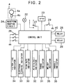
- Fig. 2 is a schematic circuit diagram of an electric control system for the continuous electrolytic ion water producing apparatus shown in Fig. 1:
- Fig. 3 is a block diagram of the controlling circuit of the controlling system shown in Fig. 2:
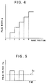
- Fig. 4 is a diagram showing a pulse width control map of pulse width controlling means of the controlling circuit shown in Fig. 3:
- Fig. 5 is a diagram showing a characteristic of a pulse voltage produced by the pulse width controlling means: and
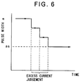
- Fig. 6 is a diagram illustrating a controlling condition of the controlling circuit of Fig. 3 when an excess current flows.
- Referring first to Fig. 1, there is shown a continuous electrolytic ion water producing apparatus in which a controlling apparatus according to the present invention is incorporated. The continuous electrolytic ion water producing apparatus shown includes an
inlet pipe 1 serving as a water pipe adapted to be connected to a city water pipe or the like to introduce city water into the continuous electrolytic ion water producing apparatus therethrough. Theinlet pipe 1 communicates with afilter cartridge 2 for removing residual chlorine in city water introduced thereto. Anoutlet pipe 3 of thefilter cartridge 2 communicates with anelectrolytic cell 5 by way of aflow rate sensor 4 of the rotary type interposed between them. Theelectrolytic cell 5 is of the enclosed type, and the exit side of the inside thereof is partitioned by a partition or the like into two sections in which a negative electrode 6 and a positive electrode 7 are disposed separately. Anoutlet pipe 8 for alkali ion water is connected to theelectrolytic cell 5 adjacent the negative electrode 6 while another outlet pipe 9 for acid ion water is connected to theelectrolytic cell 5 adjacent the positive electrode 7 so that alkali ion water and acid ion water can be extracted separately from theoutput pipes 8 and 9, respectively. - A
power source circuit 10 is provided for theelectrolytic cell 5 and includes anac power source 11 connected to the primary winding of apower source transformer 12, a secondary winding of which is connected to a rectifyingcircuit 14. The positive and negative poles of the dc voltage output side of the rectifyingcircuit 14 are connected by way of asmoothing capacitor 15 to aswitching regulator 16 of the pulse width modulating type (PWM) for controlling a dc power supply in a stepless manner. The outputs of theswitching regulator 16 are connected individually to the positive electrode 7 and the negative electrode 6 by way of apower source switch 17 and apolarity reversing switch 18. Meanwhile, in order to obtain a controlling power, another secondary winding of thepower source transformer 12 is connected by way of another rectifyingcircuit 19 and anothersmoothing capacitor 20 to aconstant voltage circuit 21, which is connected to acontrol unit 40 so that a fixed voltage may be supplied to thecontrol unit 40. - Referring now to Fig. 2, there is shown an electric control system for the continuous electrolytic ion water producing apparatus shown in Fig. 1. Referring also to Fig. 1, a
current sensor 22 for detecting an electrolytic current is provided at the secondary winding of thepower source transformer 12 connected to the rectifyingcircuit 14, and an output signal of thecurrent sensor 22 is inputted to thecontrol unit 40. Areset switch 23 is provided for thefilter cartridge 2 and resets upon exchanging of a filter, and a switch signal of thereset switch 23 is inputted to thecontrol unit 40. Theflow rate sensor 4 detects rotation of anelectromagnetic vane wheel 4a disposed in the water pipe line by means of aHall effect element 4b and outputs corresponding pulses. The pulse signal is inputted to thecontrol unit 40 by way of awaveform shaping circuit 24. Thecontrol unit 40 counts pulses of the pulse signal from theflow rate sensor 4 to detect a flow rate of water, and thepower source switch 17 is switched on and off by means of arelay 25 in response to the flow rate thus detected. Further, after stopping of flowing of water, a scale removing time is set in response to the water passing amount, and thepolarity reversing switch 18 is changed over to the oppositely connecting position by means of anotherrelay 26 in accordance with the scale removing time thus sent to automatically remove scale from the positive and negative electrodes 7 and 6. - Further connected to the
control unit 40 are an acid-alkali change-over switch 27 which is to be operated when one of acid ion water and alkali ion water is to be used, a range change-overswitch device 28 for adjusting the electrolyzing strength in a stepless manner, and amelody switch 29 which is manually operated when acid ion water is to be used. The electric control system further includes, as indicating means in the form of LEDs (light emitting diodes), aflow rate indicator 30, arange indicator 31, an acid/alkali indicator 32, anelectrode cleaning indicator 33 which indicates that scale should be removed, afilter life indicator 34, and amelody indicator 35 which gives a warning to inhibit drinking of water when acid ion water is to be used, all connected to thecontrol unit 40. - Referring now to Fig. 3, there is shown a controlling circuit of the electric control system shown in Fig. 2. The
current sensor 22 of the controlling circuit shown may be of the type wherein an electrolytic current is detected in a contactless fashion by means of a magnetic core and a magnetic sensor or an electric current is detected from a voltage drop across a resistor in the circuit. The range change-over switch device 28 includes, for example, fiveswitches over switch device 28 is constructed such that, when it should be set to its non-electrolyzing position, all of theswitches 28a to 29e are positioned to their off positions, and when it should be set to an electrolyzing position, theswitches 28a to 28e are selectively switched on as the electrolyzing strength is to be increased from its low condition. When the range is changed over, the range change-over switch 28 outputs a signal in accordance with the switching positions of theswitches 28a to 28e. The switchingregulator 16 includes a switchingelement 42 which is turned on and off by adriver 41, and afilter circuit 43 is connected to the switchingelement 42. Thefilter circuit 43 smoothes a pulse voltage Ep supplied thereto to produce an electrolyzing voltage Ec corresponding to a pulse width a of the pulse voltage Ep. - The
control unit 40 includesrange detecting means 46 for receiving a signal from the range change-over switch device 28 and detecting a range position of the range change-over switch device 28. Thecontrol unit 40 further includes pulse width controlling means 45 for receiving a pulse signal of a predetermined frequency from oscillating means 44. A range signal from the range change-over switch device 28 is inputted to the pulse width controlling means 45. The pulse width controlling means 45 sets the pulse width a to one of a plurality of stages shown in Fig. 4 in accordance with the present range position of the range change-over switch device 28, and outputs a pulse signal of the pulse width a to thedriver 41. The range signal is also inputted to anindicator circuit 47 to light up therange indicator 31 in accordance with the current range position to indicate the current range position. Thecontrol unit 40 further includes flow rate detecting means 48 for receiving a pulse signal from theflow rate sensor 4 and counting the number of pulses of the received pulse signal to detect a flow rate q. The flow rate q and the range signal are inputted to electrolysis judging means 49, at which the flow rate q is compared with a preset reference flow rate. Thus, when the flow rate q is lower than the preset reference flow rate, the electrolysis judging means 49 outputs an off signal to therelay 25 by way of a drivingcircuit 50. On the other hand, in response to the range signal when the range change-over switch device 28 is at its electrolyzing position in which one of theswitches 28a to 28e is at its on position, the electrolysis judging means 47 outputs an on signal to therelay 25 when the flow rate q is equal to or higher than the reference flow rate. - The
control unit 40 further includes an excess current preventing control system. The excess current preventing control system includes electrolytic current detecting means 51 for receiving a signal from thecurrent sensor 22 and normally detecting an electrolytic current I flowing through theelectrolytic cell 5. The thus detected electrolytic current I is inputted to excess current judging means 52. The excess current judging means 52 compares the electrolytic current I with a preset value Im of a maximum safe current conforming to the capacity of thepower source transformer 12, and operates timer means 53 when the electrolytic current I exceeds the present value Im. When such condition continues for a predetermined period of time, the excess current judging means 52 determines an excess current. Then, the excess current judging means 52 outputs a range down signal to the pulse width controlling means 45 to give an instruction to reduce the pulse width a set with reference to Fig. 4 by one step distance amount. The range down signal is inputted also to theindicator circuit 47 so that therange indicator 31 may blink to indicate the signal. Meanwhile, a signal from the electrolytic judging means 49 is inputted to the excess current judging means 52, and when an off signal is received as a result of interruption of passage of water from the electrolytic judging means 49, the initial state before the judgment is restored by the excess current judging means 52. - In operation, city water is normally introduced into the
electrolytic cell 5 by way of theinlet pipe 1. A fixed voltage is supplied to thecontrol unit 40 from theconstant voltage circuit 21 connected to the rectifyingcircuit 19 on the secondary winding side of thepower source transformer 12 so that thecontrol unit 40 can execute its controlling operation. Thus, when neither of alkali ion water and acid ion water is to be used, no pulse signal is inputted from theflow rate sensor 4 to thecontrol unit 40. Consequently, the electrolysis judging means 49 judges a rest of electrolyzing operation and outputs an off signal to therelay 25. Consequently, thepower switch 17 is turned off by therelay 25 thereby to deenergize theelectrolytic cell 5 so that the non-electrolyzing condition is thereafter kept. - Then, when water is allowed to pass through the continuous electrolytic ion water producing apparatus, the city water passes through the
filter cartridge 2, by which residual chlorine of the city water is removed. Then, the city water flows into theelectrolytic cell 5. Thereupon, a pulse signal from theflow rate sensor 4 is inputted to thecontrol unit 40, at which a flow rate q is detected. Then, in case the range change-over switch 28 is at its non-electrolyzing position in which all of theswitches 28a to 28c assume their off positions, a non-electrolyzing operation is determined by the electrolytic judging means 49 similarly as described above. Consequently, theelectrolytic cell 5 remains in the non-electrolyzing condition. Accordingly, in this instance, the city water, from which chlorine has been removed, is obtained from the continuous electrolytic ion water producing apparatus. - On the other hand, if, upon passage of water, the range change-
over switch 28 is manually operated to one of the electrolyzing strength range positions in accordance with a flow rate then, the range signal thereof is inputted to theindicator circuit 47 so that an LED of therange indicator 31 corresponding to the range position is lit to indicate the range position. Meanwhile, an electrolyzing operation is determined from the range signal by the electrolysis judging means 49, and an on signal is outputted from the electrolysis judging means 49 to therelay 25 so that thepower source switch 17 is switched on by therelay 25. Consequently, the transformed voltage on the secondary winding side of thepower source transformer 12 is converted into a dc voltage by the rectifyingcircuit 14, smoothed by the smoothingcapacitor 15 and inputted to the switchingregulator 16. In this instance, the range signal is inputted also to the pulse width controlling means 45 of thecontrol unit 40, at which a pulse width a is set in accordance with the range signal thus received, and a pulse signal of the pulse width a is outputted to thedriver 41. Consequently, the switchingelement 42 of the switchingregulator 16 operates to switch on and off in accordance with the pulse width a to produce such a pulse voltage Ep as shown in Fig. 5. The pulse voltage Ep is processed by thefilter circuit 43. - Thus, a dc supply voltage Es on the
transformer 12 is controlled to a predetermined electrolyzing voltage Ec by way of a pulse voltage Ep in accordance with the range change-over condition of the range change-over switch device 28. The electrolyzing voltage Ec is applied to the positive electrode 7 and the negative electrode 6 of theelectrolytic cell 5 by way of thepower source switch 17 and thepolarity reversing switch 18 in its regularly connecting position. Consequently, city water in theelectrolytic cell 5 is electrolyzed at an electrolyzing strength of the electrolyzing voltage Ec. Thus, if the polarity on the electrode side is changed over by thepolarity reversing switch 18 to theoutlet pipe 8 on the negative electrode 6 side, then alkali ion water containing a comparatively great amount of negative ions therein is obtained, but on the contrary if the polarity is changed over to the outlet pipe 9 on the positive electrode 7 side, then acid ion water containing a comparatively great amount of positive ions therein is obtained. - During such electrolyzing operation, an electrolytic current I supplied to the
electrolytic cell 5 in the range change-over condition described above is always detected by thecurrent sensor 22. The electrolytic current I thus detected is inputted to the excess current judging means 52, at which it is judged whether or not an excess current is flowing. In case the electrolyzing current I is smaller than its maximum safe current and accordingly is safe, the electrolyzing condition conforming to the operated condition of the range change-over switch device 28 is maintained and a predetermined PH value of electrolytic ion water produced is obtained. - On the other hand, when the flow rate is comparatively low or when the range change-
over switch device 28 is operated to a very high electrolyzing strength while the electric conductivity of water is high due to its comparatively high temperature, then the pulse width a is set to a comparatively great width so that the electrolyzing voltage Ec is controlled to a comparatively high value. Consequently, the very high electrolyzing voltage Ec is applied to theelectrolytic cell 5 while the resistance of water in theelectrolytic cell 5 is low, and as a result, a large amount of electrolytic current I flows through theelectrolytic cell 5. Then, when the electrolytic current I exceeds the preset value Im of the maximum safe current and this condition continues for more than the predetermined period of time, an excess current is determined by the excess current judging means 52. Thus, a range down signal is inputted from the excess current judging means 52 to the pulse width controlling means 45, at which the pulse width a is lowered by one step distance amount as seen from Fig. 6 so that the electrolyzing strength is automatically decreased. In this instance, as far as the determination of an excess current continues, the pulse width a is thereafter reduced by one by one step distance amount until it is settled to a pulse width as at a point of time when the determination of an excess current is cancelled. Consequently, water is electrolyzed with the electrolyzing strength conforming to the pulse width then. In this manner, the electrolytic current I is compulsorily controlled to a level below the maximum safe current, thereby preventing overheat of the power source transformer and so forth. - Further, in this instance, the
electrolytic cell 5 is continuously energized while the electrolyzing strength is controlled to a lowered condition as described above, and electrolytic ion water of a harmless PH value is obtained regularly. Meanwhile, the range down signal is inputted to theindicator circuit 47 so that therange indicator 31 effects a blinking indication to let the user know a controlling condition of decreasing the electrolyzing strength. Then, when the passage of water is interrupted, thepower source switch 17 is switched off by way of therelay 25 by the electrolysis judging means 49 to deenergize theelectrolytic cell 5 to enter a non-electrolyzing condition. Consequently, also judgment of the excess current judging means 52 is stopped, and consequently, outputtlng of the range down signal is cut and an initial condition is restored so that next judgment for an excess current is thereafter performed again. - Having now fully described the invention, it will be apparent to one of ordinary skill in the art that many changes and modifications can be made thereto without departing from the spirit and scope of the invention as set forth herein.
Claims (4)
- A controlling apparatus for a continuous electrolytic ion water producing apparatus which includes an electrolytic cell, a pair of negative and positive electrodes accommodated in said electrolytic cell and a power source circuit for applying a dc voltage between said negative and positive electrodes, comprising:
a current sensor for detecting an electrolytic current flowing through said electrolytic cell:
a range change-over switch for adjusting the electrolyzing strength to one of a plurality of stages:
a switching regulator connected in said power source circuit for controlling the dc voltage of said power source circuit to a level corresponding to a pulse width: and
a control unit for setting the pulse width to one of a plurality of stages in response to a signal from said range change-over switch, reducing the thus set pulse width when the electrolytic current detected by said current sensor is an excess current, and delivering a signal of the pulse width thus set or reduced to said switching regulator. - A controlling apparatus for a continuous electrolytic ion water producing apparatus according to claim 1, wherein said control unit includes excess current judging means for judging from a signal from said current sensor whether or not the electrolytic current is an excess current which exceeds a preset value, a driver for controlling said switching regulator to switch on and off, oscillating means, and pulse with controlling means for setting the pulse width to one of the plurality of stages in response to a signal from said range change-over switch, outputting a pulse signal of the pulse width thus set to said driver and decrementing, when an excess current is judged by said excess current judging means, the thus set pulse width by one stage distance amount in response to a range down signal from said excess current judging means.
- A controlling apparatus for a continuous electrolytic ion water producing apparatus according to claim 1, wherein said control unit causes a range indicator to blink when an excess current is judged.
- A controlling apparatus for a continuous electrolytic ion water producing apparatus according to claim 2, wherein said excess current judging means judges an excess current and outputs a range down signal when the condition wherein the electrolytic current exceeds the preset value of a maximum safe current continues for more than a fixed period of time and then restores its initial state when passage of water is interrupted.
Applications Claiming Priority (2)
| Application Number | Priority Date | Filing Date | Title |
|---|---|---|---|
| JP3290313A JP2804656B2 (en) | 1991-10-11 | 1991-10-11 | Control device for continuous electrolytic ionized water generator |
| JP290313/91 | 1991-10-11 |
Publications (1)
| Publication Number | Publication Date |
|---|---|
| EP0537526A1 true EP0537526A1 (en) | 1993-04-21 |
Family
ID=17754486
Family Applications (1)
| Application Number | Title | Priority Date | Filing Date |
|---|---|---|---|
| EP92116419A Withdrawn EP0537526A1 (en) | 1991-10-11 | 1992-09-24 | Controlling apparatus for continuous electrolytic ion water producing apparatus |
Country Status (6)
| Country | Link |
|---|---|
| US (1) | US5985108A (en) |
| EP (1) | EP0537526A1 (en) |
| JP (1) | JP2804656B2 (en) |
| KR (1) | KR0140377B1 (en) |
| CA (1) | CA2078807A1 (en) |
| TW (1) | TW239871B (en) |
Cited By (13)
| Publication number | Priority date | Publication date | Assignee | Title |
|---|---|---|---|---|
| EP0612693A1 (en) * | 1993-02-26 | 1994-08-31 | Hideo Hayakawa | Process and apparatus for improving quality of water |
| DE4410658A1 (en) * | 1994-03-26 | 1995-09-28 | Wt Wassertechn Gmbh | Method and device for treating industrial waste water by means of electrolysis |
| WO2002012137A2 (en) * | 2000-08-04 | 2002-02-14 | H2O Technologies, Limited | Method and apparatus for water treatment system for livestock and poultry use |
| WO2006071513A2 (en) * | 2004-12-28 | 2006-07-06 | Pionetics Corporation | Power supply for electrochemical ion exchange |
| US7780833B2 (en) | 2005-07-26 | 2010-08-24 | John Hawkins | Electrochemical ion exchange with textured membranes and cartridge |
| US7959780B2 (en) | 2004-07-26 | 2011-06-14 | Emporia Capital Funding Llc | Textured ion exchange membranes |
| US8562803B2 (en) | 2005-10-06 | 2013-10-22 | Pionetics Corporation | Electrochemical ion exchange treatment of fluids |
| GB2544147A (en) * | 2015-08-11 | 2017-05-10 | Miz Company Ltd | Hydrogen gas generator |
| US9757695B2 (en) | 2015-01-03 | 2017-09-12 | Pionetics Corporation | Anti-scale electrochemical apparatus with water-splitting ion exchange membrane |
| RU174537U1 (en) * | 2017-02-22 | 2017-10-19 | Федеральное государственное бюджетное образовательное учреждение высшего образования "Поволжский государственный технологический университет" | Installation for the continuous production of silver water with a high specified accuracy of the concentration of silver ions |
| RU182332U1 (en) * | 2018-03-28 | 2018-08-14 | Федеральное государственное бюджетное образовательное учреждение высшего образования "Поволжский государственный технологический университет" | Installation for the continuous production of silver water with a given concentration of silver ions |
| RU186864U1 (en) * | 2017-12-20 | 2019-02-06 | Федеральное государственное бюджетное образовательное учреждение высшего образования "Поволжский государственный технологический университет" | Installation for the continuous production of silver water |
| CN112591856A (en) * | 2020-12-04 | 2021-04-02 | 北京师范大学 | Electrocatalytic activity regulation and control method based on inert ion intercalation |
Families Citing this family (19)
| Publication number | Priority date | Publication date | Assignee | Title |
|---|---|---|---|---|
| JPH05329479A (en) * | 1992-05-29 | 1993-12-14 | Sanyo Electric Co Ltd | Alkaline water generator |
| US6200434B1 (en) * | 1998-02-27 | 2001-03-13 | Amano Corporation | Apparatus for producing electrolytic water |
| JP3443310B2 (en) * | 1998-03-09 | 2003-09-02 | ホシザキ電機株式会社 | Electrolyzed water generator |
| JP2000051858A (en) * | 1998-08-10 | 2000-02-22 | Osamu Miyake | Electrolytic ionic water maker |
| KR20020071255A (en) * | 2001-03-05 | 2002-09-12 | 주식회사 버룽 | Control apparatus for sterilization and disinfection system by metal ion under water diffusion by electric method |
| KR100476095B1 (en) * | 2002-12-09 | 2005-03-10 | 웅진코웨이주식회사 | Structure of controlling water ionizer |
| NL1022786C2 (en) * | 2003-02-26 | 2004-08-30 | Tendris Solutions Bv | Conversion circuit, system and method for performing an electrochemical process. |
| KR100669024B1 (en) * | 2005-06-18 | 2007-01-16 | 삼성전자주식회사 | Control method of ion generator |
| CN100499335C (en) * | 2005-10-13 | 2009-06-10 | 沈阳东宇馨波尔科技有限公司 | Semiconductor high-frequency switch frequency-change current change converting circuit |
| KR100653393B1 (en) * | 2006-01-03 | 2006-12-04 | 위니아만도 주식회사 | Water ionizer able to controlling the ph |
| KR100925350B1 (en) * | 2007-06-27 | 2009-11-09 | 장성만 | An purification system for manufacturing ionic-water |
| BR112014013734A8 (en) | 2011-12-06 | 2017-06-13 | Masco Corp | ozone distribution on a tap |
| AU2013313017A1 (en) * | 2012-09-07 | 2014-09-25 | Gamikon Pty Ltd | Electrolysis apparatus |
| US10767270B2 (en) | 2015-07-13 | 2020-09-08 | Delta Faucet Company | Electrode for an ozone generator |
| CA2946465C (en) | 2015-11-12 | 2022-03-29 | Delta Faucet Company | Ozone generator for a faucet |
| CN108463437B (en) | 2015-12-21 | 2022-07-08 | 德尔塔阀门公司 | Fluid delivery system comprising a disinfection device |
| JP6885758B2 (en) * | 2017-03-22 | 2021-06-16 | マクセルホールディングス株式会社 | Electrolyzed water generator |
| KR102516850B1 (en) * | 2022-05-06 | 2023-03-30 | 송인섭 | Nano water generator |
| NL2032699B1 (en) * | 2022-08-08 | 2024-02-16 | Sensiblue Ip B V | A method and device for disinfecting water and water supply system comprising said device |
Citations (2)
| Publication number | Priority date | Publication date | Assignee | Title |
|---|---|---|---|---|
| EP0329562A1 (en) * | 1988-02-18 | 1989-08-23 | Patrice Guy Noel Combe | Process for the treatment of liquids such as water, especially swimming pool water, and device and installation for carrying it out |
| US4946574A (en) * | 1989-09-11 | 1990-08-07 | Lin Chun Ew | Apparatus for the production of sterilized calcium-ion water |
Family Cites Families (5)
| Publication number | Priority date | Publication date | Assignee | Title |
|---|---|---|---|---|
| US4525253A (en) * | 1983-02-15 | 1985-06-25 | Med Products, Inc. | Method and apparatus for purification of water |
| US4734176A (en) * | 1987-01-27 | 1988-03-29 | Pure-N-Simple | Pulsed ion generator for water purification system |
| US4917782A (en) * | 1988-03-02 | 1990-04-17 | Advanced Water Systems, Inc. | Electrolytic liquid purification process and apparatus |
| JP2668087B2 (en) * | 1989-05-02 | 1997-10-27 | 株式会社イナックス | Ion water generator concentration setting device |
| JP3149138B2 (en) * | 1991-10-09 | 2001-03-26 | ミズ株式会社 | Control device for continuous electrolytic ionized water generator |
-
1991
- 1991-10-11 JP JP3290313A patent/JP2804656B2/en not_active Expired - Lifetime
-
1992
- 1992-08-25 TW TW081107452A patent/TW239871B/zh active
- 1992-09-14 US US07/944,281 patent/US5985108A/en not_active Expired - Fee Related
- 1992-09-22 CA CA002078807A patent/CA2078807A1/en not_active Abandoned
- 1992-09-24 EP EP92116419A patent/EP0537526A1/en not_active Withdrawn
- 1992-10-02 KR KR1019920018057A patent/KR0140377B1/en not_active IP Right Cessation
Patent Citations (2)
| Publication number | Priority date | Publication date | Assignee | Title |
|---|---|---|---|---|
| EP0329562A1 (en) * | 1988-02-18 | 1989-08-23 | Patrice Guy Noel Combe | Process for the treatment of liquids such as water, especially swimming pool water, and device and installation for carrying it out |
| US4946574A (en) * | 1989-09-11 | 1990-08-07 | Lin Chun Ew | Apparatus for the production of sterilized calcium-ion water |
Cited By (20)
| Publication number | Priority date | Publication date | Assignee | Title |
|---|---|---|---|---|
| EP0612693A1 (en) * | 1993-02-26 | 1994-08-31 | Hideo Hayakawa | Process and apparatus for improving quality of water |
| DE4410658A1 (en) * | 1994-03-26 | 1995-09-28 | Wt Wassertechn Gmbh | Method and device for treating industrial waste water by means of electrolysis |
| WO2002012137A2 (en) * | 2000-08-04 | 2002-02-14 | H2O Technologies, Limited | Method and apparatus for water treatment system for livestock and poultry use |
| WO2002012137A3 (en) * | 2000-08-04 | 2003-02-27 | H2O Technologies Ltd | Method and apparatus for water treatment system for livestock and poultry use |
| US7959780B2 (en) | 2004-07-26 | 2011-06-14 | Emporia Capital Funding Llc | Textured ion exchange membranes |
| WO2006071513A2 (en) * | 2004-12-28 | 2006-07-06 | Pionetics Corporation | Power supply for electrochemical ion exchange |
| WO2006071513A3 (en) * | 2004-12-28 | 2006-12-14 | Pionetics Inc | Power supply for electrochemical ion exchange |
| US7780833B2 (en) | 2005-07-26 | 2010-08-24 | John Hawkins | Electrochemical ion exchange with textured membranes and cartridge |
| US8293085B2 (en) | 2005-07-26 | 2012-10-23 | Pionetics Corporation | Cartridge having textured membrane |
| US9090493B2 (en) | 2005-10-06 | 2015-07-28 | Pionetics Corporation | Electrochemical ion exchange treatment of fluids |
| US8562803B2 (en) | 2005-10-06 | 2013-10-22 | Pionetics Corporation | Electrochemical ion exchange treatment of fluids |
| US9757695B2 (en) | 2015-01-03 | 2017-09-12 | Pionetics Corporation | Anti-scale electrochemical apparatus with water-splitting ion exchange membrane |
| GB2544147A (en) * | 2015-08-11 | 2017-05-10 | Miz Company Ltd | Hydrogen gas generator |
| US10435798B2 (en) | 2015-08-11 | 2019-10-08 | Miz Company Limited | Hydrogen gas generator |
| GB2544147B (en) * | 2015-08-11 | 2020-04-15 | Miz Company Ltd | Hydrogen gas generator |
| RU174537U1 (en) * | 2017-02-22 | 2017-10-19 | Федеральное государственное бюджетное образовательное учреждение высшего образования "Поволжский государственный технологический университет" | Installation for the continuous production of silver water with a high specified accuracy of the concentration of silver ions |
| RU186864U1 (en) * | 2017-12-20 | 2019-02-06 | Федеральное государственное бюджетное образовательное учреждение высшего образования "Поволжский государственный технологический университет" | Installation for the continuous production of silver water |
| RU182332U1 (en) * | 2018-03-28 | 2018-08-14 | Федеральное государственное бюджетное образовательное учреждение высшего образования "Поволжский государственный технологический университет" | Installation for the continuous production of silver water with a given concentration of silver ions |
| CN112591856A (en) * | 2020-12-04 | 2021-04-02 | 北京师范大学 | Electrocatalytic activity regulation and control method based on inert ion intercalation |
| CN112591856B (en) * | 2020-12-04 | 2021-12-14 | 北京师范大学 | Electrocatalytic activity regulation and control method based on inert ion intercalation |
Also Published As
| Publication number | Publication date |
|---|---|
| US5985108A (en) | 1999-11-16 |
| JP2804656B2 (en) | 1998-09-30 |
| KR0140377B1 (en) | 1998-06-15 |
| TW239871B (en) | 1995-02-01 |
| KR930007819A (en) | 1993-05-20 |
| CA2078807A1 (en) | 1993-04-12 |
| JPH05115877A (en) | 1993-05-14 |
Similar Documents
| Publication | Publication Date | Title |
|---|---|---|
| EP0537526A1 (en) | Controlling apparatus for continuous electrolytic ion water producing apparatus | |
| US5316646A (en) | Controlling apparatus for continuous electrolytic ion water producing apparatus | |
| EP1299309B1 (en) | Improved electrodeionization system | |
| US6168692B1 (en) | Apparatus for generating alkali ion water | |
| US5306409A (en) | Controlling apparatus for continuous electrolytic ion water producing apparatus | |
| EP0768279A1 (en) | Method of and apparatus for electrolyzing water | |
| EP2569254B1 (en) | Device for producing an electrochemically activated solution by means of an electrolysis process | |
| JP3192182B2 (en) | Control device for continuous electrolytic ionized water generator | |
| JP2018158290A (en) | Electrolyzed water generator | |
| JP3358236B2 (en) | Alkaline ion water purifier | |
| JPH089033B2 (en) | Continuous electrolytic ionized water generator | |
| JPH0691266A (en) | Control apparatus for continuous electrolytic water generator | |
| JP2515946B2 (en) | Electrolytic ionized water generator | |
| JP3319791B2 (en) | Electrolyzed water generator | |
| JPH07323285A (en) | Electrolyzed water producer | |
| JPH07185551A (en) | Ferromagnetic water generator | |
| JPH06134462A (en) | Ionized water generator | |
| JPH05154479A (en) | Equipment for producing electrolytically ionized water | |
| JPH07323286A (en) | Alkali ion water regulator | |
| JPH07124564A (en) | Electrolytic water making machine | |
| JPH07290059A (en) | Ionized water producer | |
| JP2000064082A (en) | Power source circuit of hypochlorite forming device | |
| JPH08132048A (en) | Electrolytic water forming apparatus | |
| JPH06238278A (en) | Control device for continuous electrolysis produced water generator | |
| JPH06238276A (en) | Control device of continuous electrolysis-produced water generator |
Legal Events
| Date | Code | Title | Description |
|---|---|---|---|
| PUAI | Public reference made under article 153(3) epc to a published international application that has entered the european phase |
Free format text: ORIGINAL CODE: 0009012 |
|
| AK | Designated contracting states |
Kind code of ref document: A1 Designated state(s): DE FR GB IT |
|
| 17P | Request for examination filed |
Effective date: 19930923 |
|
| RAP1 | Party data changed (applicant data changed or rights of an application transferred) |
Owner name: MIZ CO., LTD. |
|
| 17Q | First examination report despatched |
Effective date: 19950202 |
|
| STAA | Information on the status of an ep patent application or granted ep patent |
Free format text: STATUS: THE APPLICATION IS DEEMED TO BE WITHDRAWN |
|
| 18D | Application deemed to be withdrawn |
Effective date: 19950829 |