EP0536762A1 - Diamond cutter insert with a convex cutting surface - Google Patents
Diamond cutter insert with a convex cutting surface Download PDFInfo
- Publication number
- EP0536762A1 EP0536762A1 EP92117229A EP92117229A EP0536762A1 EP 0536762 A1 EP0536762 A1 EP 0536762A1 EP 92117229 A EP92117229 A EP 92117229A EP 92117229 A EP92117229 A EP 92117229A EP 0536762 A1 EP0536762 A1 EP 0536762A1
- Authority
- EP
- European Patent Office
- Prior art keywords
- diamond
- bit
- insert
- rock bit
- set forth
- Prior art date
- Legal status (The legal status is an assumption and is not a legal conclusion. Google has not performed a legal analysis and makes no representation as to the accuracy of the status listed.)
- Granted
Links
- 229910003460 diamond Inorganic materials 0.000 title claims abstract description 92
- 239000010432 diamond Substances 0.000 title claims abstract description 92
- 238000005520 cutting process Methods 0.000 title claims abstract description 33
- 239000000758 substrate Substances 0.000 claims abstract description 18
- 230000015572 biosynthetic process Effects 0.000 claims abstract description 12
- UONOETXJSWQNOL-UHFFFAOYSA-N tungsten carbide Chemical compound [W+]#[C-] UONOETXJSWQNOL-UHFFFAOYSA-N 0.000 claims abstract description 11
- 239000011435 rock Substances 0.000 claims description 16
- 238000005553 drilling Methods 0.000 claims description 14
- 239000012530 fluid Substances 0.000 claims description 9
- 238000010008 shearing Methods 0.000 claims 1
- 239000002131 composite material Substances 0.000 abstract description 12
- 230000009471 action Effects 0.000 abstract description 4
- 238000005755 formation reaction Methods 0.000 description 9
- 230000035515 penetration Effects 0.000 description 8
- 230000004044 response Effects 0.000 description 5
- 230000008901 benefit Effects 0.000 description 4
- 239000011230 binding agent Substances 0.000 description 4
- 239000011159 matrix material Substances 0.000 description 4
- 238000001816 cooling Methods 0.000 description 3
- 238000005516 engineering process Methods 0.000 description 3
- 229910052751 metal Inorganic materials 0.000 description 3
- 239000002184 metal Substances 0.000 description 3
- 238000004140 cleaning Methods 0.000 description 2
- 229910017052 cobalt Inorganic materials 0.000 description 2
- 239000010941 cobalt Substances 0.000 description 2
- GUTLYIVDDKVIGB-UHFFFAOYSA-N cobalt atom Chemical compound [Co] GUTLYIVDDKVIGB-UHFFFAOYSA-N 0.000 description 2
- 230000006378 damage Effects 0.000 description 2
- 230000032798 delamination Effects 0.000 description 2
- 238000011010 flushing procedure Methods 0.000 description 2
- 238000004519 manufacturing process Methods 0.000 description 2
- 230000009467 reduction Effects 0.000 description 2
- 238000005219 brazing Methods 0.000 description 1
- 230000015556 catabolic process Effects 0.000 description 1
- 239000003054 catalyst Substances 0.000 description 1
- 230000008859 change Effects 0.000 description 1
- 238000010276 construction Methods 0.000 description 1
- 239000012809 cooling fluid Substances 0.000 description 1
- 125000004122 cyclic group Chemical group 0.000 description 1
- 238000006731 degradation reaction Methods 0.000 description 1
- 230000020169 heat generation Effects 0.000 description 1
- 238000010438 heat treatment Methods 0.000 description 1
- 230000000266 injurious effect Effects 0.000 description 1
- 239000000463 material Substances 0.000 description 1
- 238000000034 method Methods 0.000 description 1
- 239000000203 mixture Substances 0.000 description 1
- 230000004048 modification Effects 0.000 description 1
- 238000012986 modification Methods 0.000 description 1
- 238000005457 optimization Methods 0.000 description 1
- 239000002245 particle Substances 0.000 description 1
- 239000011148 porous material Substances 0.000 description 1
- 230000008569 process Effects 0.000 description 1
- 238000005245 sintering Methods 0.000 description 1
- 239000003381 stabilizer Substances 0.000 description 1
- 230000007704 transition Effects 0.000 description 1
Images


Classifications
-
- E—FIXED CONSTRUCTIONS
- E21—EARTH DRILLING; MINING
- E21B—EARTH DRILLING, e.g. DEEP DRILLING; OBTAINING OIL, GAS, WATER, SOLUBLE OR MELTABLE MATERIALS OR A SLURRY OF MINERALS FROM WELLS
- E21B10/00—Drill bits
- E21B10/46—Drill bits characterised by wear resisting parts, e.g. diamond inserts
- E21B10/56—Button-type inserts
- E21B10/567—Button-type inserts with preformed cutting elements mounted on a distinct support, e.g. polycrystalline inserts
- E21B10/5673—Button-type inserts with preformed cutting elements mounted on a distinct support, e.g. polycrystalline inserts having a non planar or non circular cutting face
Definitions
- the present invention relates to diamond drag bits having cylindrical polycrystalline diamond faced inserts imbedded in the cutting face of a drag bit.
- the present invention relates to the optimization of the geometry of the cutting face of cutting elements, particularly of the type in which a diamond layer or other superhard material is adhered to a cemented carbide substrate to form a composite, and the composite is bonded to or integral with a support stud or cylinder.
- One type of cutting element used in rotary drilling operations in subterranean earth formations comprises an abrasive composite or compact mounted on a support cylinder or stud.
- the composite typically comprises a diamond layer adhered to a cemented carbide substrate, e.g., cemented tungsten carbide, containing a metal binder such as cobalt, and the substrate is brazed to the support cylinder or stud.
- the support cemented tungsten carbide cylinder may be integrally formed as part of the polycrystalline diamond substrate backing. Mounting of these cutting elements in a drilling bit is achieved by press fitting, brazing or otherwise securing the stud or cylinder into pre-drilled holes in the drill bit head.
- Fabrication of the composite is typically achieved by placing a cemented carbide cylinder into the working volume of a press. A mixture of diamond grains and a catalyst binder is placed atop the substrate and is compressed under ultra-high pressure and temperature conditions. In so doing, the metal binder migrates from the substrate and "sweeps" through the diamond grains to promote a sintering of the diamond grains. As a result, the diamond grains become bonded to each other to form a diamond layer and also bonded to the substrate along a planar interface. Metal binder (e.g. cobalt) remains disposed within the pores defined between the diamond grains.
- Metal binder e.g. cobalt
- a composite formed in this manner may be subject to a number of shortcomings.
- the coefficient of thermal expansion of the cemented tungsten carbide and diamond are somewhat close, but not exactly the same.
- the heating and cooling of the composite in the manufacturing process or during the work cycles the cutter undergoes in the drilling process create significantly high cyclic tensile stresses at the boundary of the diamond layer and the tungsten carbide substrate.
- the magnitude of these stresses is a function of the disparity of the thermal expansion coefficients. These stresses are quite often of such magnitude to cause delamination of the diamond layer.
- Another shortcoming of state of the art diamond composite compact technology described above is the difficulty of producing a composite compact with any shape other than a flat planar diamond cutting layer that has low enough residual tensile stresses at the diamond/carbide interface that will permit its use as a drilling tool.
- One object of the present invention is to modify the curvature geometry of the diamond cutting surface to significantly increase the drilling rate of the bit compared to the prior art.
- This curvature radius is optimized to the extent that, for a given range of rock strengths and types, the curvature gives the optimum back rake angle (negative rake angle) range to provide the best shear action on the rock considering the internal friction factor for that range of geological formations.
- a preferred diamond rock bit has one or more diamond inserts secured within a first cutting face formed on a rock bit body.
- the body has a second open threaded pin end, a fluid chamber and one or more nozzle passages through the cutting face.
- Such a diamond insert comprises a diamond cutter end, an intermediate cylindrical body and a base end.
- the cutter end has a convex surface with a radius from five to six times the radius of the cylindrical body.
- the curved surface provides positive and negative side rake angles to deflect detritus from the curved diamond surface and to help cool and clean the diamond cutters while drilling an earthen formation.
- the curvature radius is optimized to the extent that, for a given range of rock strengths and types, the curvature gives the optimum back rake angle range to provide the best shear action on the rock formation.
- the idealized curvature of the diamond cutting surface provides both positive and negative side rake to promote removal of drilled cuttings or other detritus from the cutting face, thereby presenting a clean cutting edge to the formation.
- the curved side rake surfaces are constantly wiped clean providing for constant drilling fluid flushing the diamond cutting edge. This greatly aids in cooling the cutters below their thermal degradation limit. This permits less wear on the cutter and greater drilling life.
- FIGURE 1 illustrates a diamond drag rock bit generally designated as 10.
- the drag bit comprises a bit body 12, threaded pin end 14 and cutting end generally designated as 16.
- a pair of tool groove slots 13 on opposite sides of the bit body 12 provide a means to remove the bit from a drill string (not shown).
- a bit face 18 that contains a multiplicity of diamond faced cylindrical studs generally designated as 20 extending therefrom.
- a diamond stud 20 for example, comprises a diamond disc 22, a cylindrical backing support segment 24 and a cylindrical stud body 26.
- the disc 22 is fabricated from a cemented tungsten carbide substrate 24 with a polycrystalline diamond layer sintered to the face of the substrate.
- the diamond layer for example, is formed with a convex surface having a radius between five and six times the radius of the stud body 26.
- the convex surface preferably forms a portion of a sphere with a radius about five times the radius of the stud body 26.
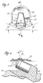
- FIGURE 2 illustrates the cutting end of the bit with the inserts 20 imbedded in, for example, a matrix of cemented tungsten carbide making up the head of the bit.
- Each of the inserts is strategically positioned in the face 18 of the bit.
- Formed in the cutting face of the bit is one or more fluid passages generally designated as 30.
- Each fluid passage communicates with a plenum chamber (not shown) formed within the bit body.
- a nozzle 34 is, for example, threaded into a nozzle opening 33 at the end of the fluid passage 30. Drilling fluid or "mud" is directed out of the nozzles 34 toward a borehole bottom 35 (Fig. 6) to clear detritus 37 from the bottom and to cool and clean each of the diamond inserts 20.
- the cutting face 18 additionally has raised ridges 40 that support insert protrusions 41.
- Each insert protrusion 41 partially encapsulates the base 26 of an insert.
- Each insert is positioned with the convex diamond disc 22 at a negative rake angle "A" with respect to the bottom of the borehole 35 (Fig. 6), that is, a negative rake angle relative to a plane transverse to the bit axis.
- a negative rake angle "A" with respect to the bottom of the borehole 35 (Fig. 6), that is, a negative rake angle relative to a plane transverse to the bit axis.
- FIGURE 3a illustrates a typical diamond domed insert 50 with a cylindrical base 51 having a 0.500 inch (12.7 mm) diameter with a dome radius of 0.500 inch (12.7 mm). While the foregoing domed insert 50 has many attributes of the present invention, it does not have the penetration rate of the insert 20. The slightly convex surface of disc 22 more closely approximates the fast penetration rate of a flat diamond insert 54 illustrated in the prior art of FIGURE 3b.
- the insert 54 has a cylindrical body 56 with a flat diamond disc 58 sintered to a tungsten carbide substrate cylinder 60 that is typically brazed to the body 56.
- the flat diamond insert 54 has been demonstrated to have an excellent penetration rate however, detritus build up in front of each disc 58 during bit operation in a borehole results in heat generation and ineffective cleaning and cooling that unfortunately equates to short bit life and early destruction of the diamond cutters 54.
- the diamond inserts 20 with a relatively large convex radius to the diamond cutting face 22 has the advantage of a fast penetration rate such as that demonstrated by the flat diamond cutter while retaining the detritus deflecting capabilities of the foregoing prior art dome cutter 50.
- the slightly domed insert 20 thus incorporates the best features of the prior art cutters 50 and 54 with none of the undesirable characteristics of either.
- FIGURE 5 illustrates an insert 20 mounted in a raised protrusion 42 extending above a ridge 40.
- the cutting end 16 affixed to bit body 12 is preferably fabricated from a matrix of tungsten carbide 19 molded in a female die.
- the die for example, forms insert pockets, raised protrusions 42, ridges 40, fluid passages 33, face 18, etc.
- Each insert 20 is partially encapsulated in the matrix 19 and is angled such that the end diamond disc 22 is at a negative rake angle "A" (Fig. 6).
- This angle "A” is between ten and twenty degrees with respect to a borehole bottom 35.
- the preferred rake angle is 20 degrees.
- the side rake angle is relative to a radial line from the center of the bit. If one has a flat cutter face, a positive side rake angle is presented when the cutter face is skewed with the edge nearer the center of the bit trailing the edge nearer the periphery of the bit. Conversely, a negative rake angle is when the edge of a flat cutter face is skewed so that the edge of the cutter face nearer the periphery of the bit trails the edge of the cutter face nearer the center of the bit.
- the slightly convex curvature of the present insert means that there is positive rake toward the center of the bit, while at the same time there is negative rake toward the periphery. This permits detritus to move laterally in both directions. The double cleaning action is obtained without sacrificing the desirable negative rake in the longitudinal direction on the bit (Fig. 6) because of the small curvature.
- An advantage of the present invention over the prior art is that the rearwardly curved surfaces of the inserts perform as small individual bit stabilizers, reducing the tendency of the drag bit to drill off-center, gyrate or whirl. This substantially reduces the injurious vibrations common to prior art flat face cutter bits. Minimizing vibrations greatly reduces impact damage to the diamond cutter edges and faces, thereby measurably increasing the life expectancy of the bit.
- An advantage of importance in the present invention is maintaining or increasing the physical strength and wear resistance of the diamond cutters. This is provided by having optimum diamond surface curvature to provide high drilling rates, but concurrently putting the diamond layer in a high compressive stress which minimizes delamination, chipping or fracturing of the diamond layer.
- FIGURE 7 the chart illustrates a reduction in torque when a domed insert (20 and 50) is utilized.
- the flat diamond inserts 54 tend to easily torque up and as a result, vibrate badly in a formation.
- the dome insert 50 of the prior art while it has less of a tendency to torque up and vibrate, bit penetration rate is far less than the flat faced prior art insert 54.
- the chart of FIGURE 9 indicates as the RPM (revolutions per minute) increases, the ROP is better for the second generation insert 20 than the prior art flat insert 54 and much better than the first generation dome insert 50.
- FIGURE 10 chart reveals the extended life of the insert 20 of the present invention over both the flat and dome inserts of the prior art.
Abstract
Description
- The present invention relates to diamond drag bits having cylindrical polycrystalline diamond faced inserts imbedded in the cutting face of a drag bit.
- More particularly, the present invention relates to the optimization of the geometry of the cutting face of cutting elements, particularly of the type in which a diamond layer or other superhard material is adhered to a cemented carbide substrate to form a composite, and the composite is bonded to or integral with a support stud or cylinder.
- One type of cutting element used in rotary drilling operations in subterranean earth formations comprises an abrasive composite or compact mounted on a support cylinder or stud. The composite typically comprises a diamond layer adhered to a cemented carbide substrate, e.g., cemented tungsten carbide, containing a metal binder such as cobalt, and the substrate is brazed to the support cylinder or stud. Alternatively, the support cemented tungsten carbide cylinder may be integrally formed as part of the polycrystalline diamond substrate backing. Mounting of these cutting elements in a drilling bit is achieved by press fitting, brazing or otherwise securing the stud or cylinder into pre-drilled holes in the drill bit head.
- Fabrication of the composite is typically achieved by placing a cemented carbide cylinder into the working volume of a press. A mixture of diamond grains and a catalyst binder is placed atop the substrate and is compressed under ultra-high pressure and temperature conditions. In so doing, the metal binder migrates from the substrate and "sweeps" through the diamond grains to promote a sintering of the diamond grains. As a result, the diamond grains become bonded to each other to form a diamond layer and also bonded to the substrate along a planar interface. Metal binder (e.g. cobalt) remains disposed within the pores defined between the diamond grains.
- A composite formed in this manner may be subject to a number of shortcomings. For example, the coefficient of thermal expansion of the cemented tungsten carbide and diamond are somewhat close, but not exactly the same. Thus, the heating and cooling of the composite in the manufacturing process or during the work cycles the cutter undergoes in the drilling process, create significantly high cyclic tensile stresses at the boundary of the diamond layer and the tungsten carbide substrate. The magnitude of these stresses is a function of the disparity of the thermal expansion coefficients. These stresses are quite often of such magnitude to cause delamination of the diamond layer.
- This limitation has been greatly minimized by adding a transition layer of mixed diamond particles and pre-sintered tungsten carbide between the full diamond layer and the carbide substrate, as taught by U.S. Patent Numbers 4,525,178 and 4,604,106.
- Another shortcoming of state of the art diamond composite compact technology described above is the difficulty of producing a composite compact with any shape other than a flat planar diamond cutting layer that has low enough residual tensile stresses at the diamond/carbide interface that will permit its use as a drilling tool.
- Using the technology of the above described U.S. patents, it is relatively simple to produce diamond composite compacts with concave, convex or other non flat cutting surfaces. This allows much greater freedom of design of drag type diamond compact drilling bits that are fitted with diamond cutters having significantly greater impact strength and wear resistance. This technology is taught in U.S. Patent Number 4,858,707.
- One object of the present invention is to modify the curvature geometry of the diamond cutting surface to significantly increase the drilling rate of the bit compared to the prior art. This curvature radius is optimized to the extent that, for a given range of rock strengths and types, the curvature gives the optimum back rake angle (negative rake angle) range to provide the best shear action on the rock considering the internal friction factor for that range of geological formations.
- A preferred diamond rock bit has one or more diamond inserts secured within a first cutting face formed on a rock bit body. The body has a second open threaded pin end, a fluid chamber and one or more nozzle passages through the cutting face. Such a diamond insert comprises a diamond cutter end, an intermediate cylindrical body and a base end. The cutter end has a convex surface with a radius from five to six times the radius of the cylindrical body. The curved surface provides positive and negative side rake angles to deflect detritus from the curved diamond surface and to help cool and clean the diamond cutters while drilling an earthen formation.
- The curvature radius is optimized to the extent that, for a given range of rock strengths and types, the curvature gives the optimum back rake angle range to provide the best shear action on the rock formation. The idealized curvature of the diamond cutting surface provides both positive and negative side rake to promote removal of drilled cuttings or other detritus from the cutting face, thereby presenting a clean cutting edge to the formation.
- The curved side rake surfaces are constantly wiped clean providing for constant drilling fluid flushing the diamond cutting edge. This greatly aids in cooling the cutters below their thermal degradation limit. This permits less wear on the cutter and greater drilling life.
- The above noted objects and advantages of the present invention will be more fully understood upon a study of the following description in conjunction with the detailed drawings wherein:
- FIGURE 1 is a perspective view of a diamond drag bit of the present invention;
- FIGURE 2 is a top view of the cutting head of the drag bit;
- FIGURES 3a and 3b depict a side view of a prior art diamond dome insert and a prior art diamond flat disc type insert, respectively;
- FIGURE 4 is a side view of a diamond insert of the present invention having a slightly convex diamond cutter disc with a disc cutter radius about five times the radius of the supporting stud body;
- FIGURE 5 is a top view of one of the cylindrical diamond inserts secured in a matrix forming the face of the drag bit;
- FIGURE 6 is a partial cross-section of a cylindrical diamond cutter illustrating the varying negative rake angle of the convex diamond face as the insert penetrates an earthen formation;
- FIGURE 7 is a chart indicating torque response of a dome vs. flat diamond cutter;
- FIGURE 8 is a chart comparing weight response of a flat vs. first and second generation diamond dome cutters;
- FIGURE 9 is a chart comparing RPM response of a flat vs. first and second generation diamond dome cutters; and
- FIGURE 10 is a cutter life chart comparing a flat vs. first and second generation diamond dome cutters.
- FIGURE 1 illustrates a diamond drag rock bit generally designated as 10. The drag bit comprises a
bit body 12, threadedpin end 14 and cutting end generally designated as 16. A pair oftool groove slots 13 on opposite sides of thebit body 12 provide a means to remove the bit from a drill string (not shown). - At the
cutting end 16 is formed abit face 18 that contains a multiplicity of diamond faced cylindrical studs generally designated as 20 extending therefrom. Such adiamond stud 20, for example, comprises adiamond disc 22, a cylindricalbacking support segment 24 and acylindrical stud body 26. - The
disc 22 is fabricated from a cementedtungsten carbide substrate 24 with a polycrystalline diamond layer sintered to the face of the substrate. The diamond layer, for example, is formed with a convex surface having a radius between five and six times the radius of thestud body 26. The convex surface preferably forms a portion of a sphere with a radius about five times the radius of thestud body 26. - FIGURE 2 illustrates the cutting end of the bit with the
inserts 20 imbedded in, for example, a matrix of cemented tungsten carbide making up the head of the bit. Each of the inserts is strategically positioned in theface 18 of the bit. Formed in the cutting face of the bit is one or more fluid passages generally designated as 30. Each fluid passage communicates with a plenum chamber (not shown) formed within the bit body. Anozzle 34 is, for example, threaded into a nozzle opening 33 at the end of thefluid passage 30. Drilling fluid or "mud" is directed out of thenozzles 34 toward a borehole bottom 35 (Fig. 6) to cleardetritus 37 from the bottom and to cool and clean each of thediamond inserts 20. - The
cutting face 18 additionally has raisedridges 40 that support insert protrusions 41. Each insert protrusion 41 partially encapsulates thebase 26 of an insert. Each insert is positioned with theconvex diamond disc 22 at a negative rake angle "A" with respect to the bottom of the borehole 35 (Fig. 6), that is, a negative rake angle relative to a plane transverse to the bit axis. Obviously, with a convex or spherically shapeddisc 22, the deeper the diamond cutter penetrates the formation 35, the negative rake angle will change accordingly. The rake angle "A" will be less negative the deeper the penetration of thedisc 22. - Moreover, with reference to FIGURE 5, since the
disc 22 is convex,detritus 37 is deflected away (angle "B") from the diamond cutting surfaces 39, hence flushing and cooling fluid is more readily able to maintain the integrity of the diamond during operation of the bit in a borehole. - The prior art depicted in FIGURE 3a illustrates a typical diamond
domed insert 50 with acylindrical base 51 having a 0.500 inch (12.7 mm) diameter with a dome radius of 0.500 inch (12.7 mm). While the foregoingdomed insert 50 has many attributes of the present invention, it does not have the penetration rate of theinsert 20. The slightly convex surface ofdisc 22 more closely approximates the fast penetration rate of aflat diamond insert 54 illustrated in the prior art of FIGURE 3b. - Referring now to the prior art shown in FIGURE 3b, the
insert 54 has acylindrical body 56 with aflat diamond disc 58 sintered to a tungsten carbide substrate cylinder 60 that is typically brazed to thebody 56. Theflat diamond insert 54 has been demonstrated to have an excellent penetration rate however, detritus build up in front of eachdisc 58 during bit operation in a borehole results in heat generation and ineffective cleaning and cooling that unfortunately equates to short bit life and early destruction of thediamond cutters 54. - The diamond inserts 20 with a relatively large convex radius to the
diamond cutting face 22 has the advantage of a fast penetration rate such as that demonstrated by the flat diamond cutter while retaining the detritus deflecting capabilities of the foregoing priorart dome cutter 50. The slightlydomed insert 20 thus incorporates the best features of theprior art cutters - Referring now to FIGURES 5 and 6, FIGURE 5 illustrates an
insert 20 mounted in a raisedprotrusion 42 extending above aridge 40. The cuttingend 16 affixed to bitbody 12 is preferably fabricated from a matrix of tungsten carbide 19 molded in a female die. The die, for example, forms insert pockets, raisedprotrusions 42,ridges 40,fluid passages 33,face 18, etc. - Each
insert 20 is partially encapsulated in the matrix 19 and is angled such that theend diamond disc 22 is at a negative rake angle "A" (Fig. 6). This angle "A" is between ten and twenty degrees with respect to a borehole bottom 35. The preferred rake angle is 20 degrees. - The top of such an insert 20 (Fig. 5) with the slightly
curved surface 23 provides both positive and negative side rake angles relative to a radial line and deflects debris away from an apex of thedisc 22. This characteristic is indicated by angle "B". As heretofore described, detritus does not build up against thecurved face 23 hence, the cutting face stays free of obstruction. The drilling rig mud or fluid easily cleans and cools each of the multiple diamond inserts affixed within the face of the cutting head. - The side rake angle is relative to a radial line from the center of the bit. If one has a flat cutter face, a positive side rake angle is presented when the cutter face is skewed with the edge nearer the center of the bit trailing the edge nearer the periphery of the bit. Conversely, a negative rake angle is when the edge of a flat cutter face is skewed so that the edge of the cutter face nearer the periphery of the bit trails the edge of the cutter face nearer the center of the bit. The slightly convex curvature of the present insert means that there is positive rake toward the center of the bit, while at the same time there is negative rake toward the periphery. This permits detritus to move laterally in both directions. The double cleaning action is obtained without sacrificing the desirable negative rake in the longitudinal direction on the bit (Fig. 6) because of the small curvature.
- An advantage of the present invention over the prior art is that the rearwardly curved surfaces of the inserts perform as small individual bit stabilizers, reducing the tendency of the drag bit to drill off-center, gyrate or whirl. This substantially reduces the injurious vibrations common to prior art flat face cutter bits. Minimizing vibrations greatly reduces impact damage to the diamond cutter edges and faces, thereby measurably increasing the life expectancy of the bit.
- Moreover, the use of curved diamond surfaces shows a marked reduction in damaging torque variations when drilling broken or laminated formations.
- An advantage of importance in the present invention is maintaining or increasing the physical strength and wear resistance of the diamond cutters. This is provided by having optimum diamond surface curvature to provide high drilling rates, but concurrently putting the diamond layer in a high compressive stress which minimizes delamination, chipping or fracturing of the diamond layer.
- Referring now to FIGURE 7, the chart illustrates a reduction in torque when a domed insert (20 and 50) is utilized. The flat diamond inserts 54 tend to easily torque up and as a result, vibrate badly in a formation. With the
dome insert 50 of the prior art, while it has less of a tendency to torque up and vibrate, bit penetration rate is far less than the flat facedprior art insert 54. - This phenomenon is clearly shown in the weight response chart of FIGURE 8 and the RPM response chart of FIGURE 9. In FIGURE 8, the ROP (rate of penetration) is increased for the second generation
domed insert 20 of the present invention over both the priorart dome insert 50 and theflat insert 54. As the WOB (weight on bit) increases, the bit penetration "tails off" for both the prior art dome and flat insert type bits. - The chart of FIGURE 9 indicates as the RPM (revolutions per minute) increases, the ROP is better for the
second generation insert 20 than the prior artflat insert 54 and much better than the firstgeneration dome insert 50. - Finally, the FIGURE 10 chart reveals the extended life of the
insert 20 of the present invention over both the flat and dome inserts of the prior art. - It will of course be realized that various modifications can be made in the design and operation of the present invention without departing from the spirit thereof. Thus, while the principal preferred construction and mode of operation of the invention have been explained in what is now considered to represent its best embodiments, which have been illustrated and described, it should be understood that within the scope of the appended claims, the invention may be practiced otherwise than as specifically illustrated and described.
Claims (7)
- A diamond rock bit having one or more diamond inserts secured within a first cutting face formed on a rock bit body, the body further having a second open threaded pin end, a fluid chamber and one or more nozzle passages through the cutting face, such a diamond insert comprising a diamond cutter end, an intermediate cylindrical body and a base end, and characterized by the cutter end having a convex surface with a radius between five and six times the radius of the cylindrical body, the convex diamond cutter end providing optimum rock shearing ability, and positive and negative side rake angles to deflect detritus from the convex diamond face and to help cool and clean the diamond cutters while drilling an earthen formation.
- A diamond rock bit as set forth in claim 1 wherein the convex surface is a portion of a sphere atop a cylindrical substrate, the substrate being secured to the cylindrical body.
- A diamond rock bit as set forth in either of claims 1 or 2 wherein the cylindrical substrate and the cylindrical body are tungsten carbide.
- A diamond rock bit as set forth in any of the preceding claims wherein the diamond cutter end comprises polycrystalline diamond sintered to the substrate.
- A diamond rock bit as set forth in any of the preceding claims wherein the one diamond inserts are secured within the first cutting face of the bit body with a negative rake angle with respect to a plane transverse to the bit axis.
- A diamond rock bit as set forth in claim 5 wherein the negative rake angle with respect to a transverse plane is between ten and twenty degrees.
- A diamond rock bit as set forth in claim 6 wherein the negative rake angle with respect to a transverse plane is 20 degrees.
Applications Claiming Priority (2)
| Application Number | Priority Date | Filing Date | Title |
|---|---|---|---|
| US77477591A | 1991-10-09 | 1991-10-09 | |
| US774775 | 1991-10-09 |
Publications (2)
| Publication Number | Publication Date |
|---|---|
| EP0536762A1 true EP0536762A1 (en) | 1993-04-14 |
| EP0536762B1 EP0536762B1 (en) | 1997-09-03 |
Family
ID=25102261
Family Applications (1)
| Application Number | Title | Priority Date | Filing Date |
|---|---|---|---|
| EP92117229A Expired - Lifetime EP0536762B1 (en) | 1991-10-09 | 1992-10-08 | Diamond cutter insert with a convex cutting surface |
Country Status (3)
| Country | Link |
|---|---|
| US (1) | US5332051A (en) |
| EP (1) | EP0536762B1 (en) |
| DE (1) | DE69221983D1 (en) |
Cited By (2)
| Publication number | Priority date | Publication date | Assignee | Title |
|---|---|---|---|---|
| BE1012752A5 (en) * | 1997-09-08 | 2001-03-06 | Baker Hughes Inc | Rotary drill bits DIRECTIONAL DRILLING FOR HAVING CUP FEATURES VARIABLE WEIGHT APPLY DEPENDING ON THE DRILL. |
| CN108625789A (en) * | 2018-05-22 | 2018-10-09 | 西南石油大学 | The composite drill bit of Split teeth wheel and PDC |
Families Citing this family (76)
| Publication number | Priority date | Publication date | Assignee | Title |
|---|---|---|---|---|
| US5433280A (en) * | 1994-03-16 | 1995-07-18 | Baker Hughes Incorporated | Fabrication method for rotary bits and bit components and bits and components produced thereby |
| US5839329A (en) | 1994-03-16 | 1998-11-24 | Baker Hughes Incorporated | Method for infiltrating preformed components and component assemblies |
| US6209420B1 (en) | 1994-03-16 | 2001-04-03 | Baker Hughes Incorporated | Method of manufacturing bits, bit components and other articles of manufacture |
| US6073518A (en) * | 1996-09-24 | 2000-06-13 | Baker Hughes Incorporated | Bit manufacturing method |
| DE69531277T2 (en) * | 1994-10-15 | 2004-05-19 | Camco Drilling Group Ltd., Stonehouse | A rotary drill bit |
| US5636700A (en) | 1995-01-03 | 1997-06-10 | Dresser Industries, Inc. | Roller cone rock bit having improved cutter gauge face surface compacts and a method of construction |
| US5709278A (en) | 1996-01-22 | 1998-01-20 | Dresser Industries, Inc. | Rotary cone drill bit with contoured inserts and compacts |
| US5924501A (en) * | 1996-02-15 | 1999-07-20 | Baker Hughes Incorporated | Predominantly diamond cutting structures for earth boring |
| US5706906A (en) * | 1996-02-15 | 1998-01-13 | Baker Hughes Incorporated | Superabrasive cutting element with enhanced durability and increased wear life, and apparatus so equipped |
| US5722497A (en) | 1996-03-21 | 1998-03-03 | Dresser Industries, Inc. | Roller cone gage surface cutting elements with multiple ultra hard cutting surfaces |
| US6021858A (en) * | 1996-06-05 | 2000-02-08 | Smith International, Inc. | Drill bit having trapezium-shaped blades |
| US5794703A (en) * | 1996-07-03 | 1998-08-18 | Ctes, L.C. | Wellbore tractor and method of moving an item through a wellbore |
| US6353771B1 (en) | 1996-07-22 | 2002-03-05 | Smith International, Inc. | Rapid manufacturing of molds for forming drill bits |
| GB9621217D0 (en) * | 1996-10-11 | 1996-11-27 | Camco Drilling Group Ltd | Improvements in or relating to preform cutting elements for rotary drill bits |
| US5881830A (en) * | 1997-02-14 | 1999-03-16 | Baker Hughes Incorporated | Superabrasive drill bit cutting element with buttress-supported planar chamfer |
| US5950745A (en) * | 1997-08-18 | 1999-09-14 | Sandvik Ab | Diamond-coated button insert for drilling |
| US6202772B1 (en) | 1998-06-24 | 2001-03-20 | Smith International | Cutting element with canted design for improved braze contact area |
| US6220375B1 (en) | 1999-01-13 | 2001-04-24 | Baker Hughes Incorporated | Polycrystalline diamond cutters having modified residual stresses |
| US6454030B1 (en) | 1999-01-25 | 2002-09-24 | Baker Hughes Incorporated | Drill bits and other articles of manufacture including a layer-manufactured shell integrally secured to a cast structure and methods of fabricating same |
| US6200514B1 (en) | 1999-02-09 | 2001-03-13 | Baker Hughes Incorporated | Process of making a bit body and mold therefor |
| US6283234B1 (en) * | 1999-09-17 | 2001-09-04 | Sylvan Engineering Company | Apparatus for mounting PCD compacts |
| US6730998B1 (en) * | 2000-02-10 | 2004-05-04 | Micron Technology, Inc. | Stereolithographic method for fabricating heat sinks, stereolithographically fabricated heat sinks, and semiconductor devices including same |
| US6394198B1 (en) * | 2000-06-26 | 2002-05-28 | David R. Hall | Frictional vibration damper for downhole tools |
| US6432752B1 (en) * | 2000-08-17 | 2002-08-13 | Micron Technology, Inc. | Stereolithographic methods for fabricating hermetic semiconductor device packages and semiconductor devices including stereolithographically fabricated hermetic packages |
| CA2454016C (en) * | 2002-12-23 | 2009-05-12 | Smith International, Inc. | Ribless bit with diamond impregnated cutter elements |
| US7726420B2 (en) * | 2004-04-30 | 2010-06-01 | Smith International, Inc. | Cutter having shaped working surface with varying edge chamfer |
| US7798257B2 (en) * | 2004-04-30 | 2010-09-21 | Smith International, Inc. | Shaped cutter surface |
| US20050247486A1 (en) * | 2004-04-30 | 2005-11-10 | Smith International, Inc. | Modified cutters |
| US7223049B2 (en) * | 2005-03-01 | 2007-05-29 | Hall David R | Apparatus, system and method for directional degradation of a paved surface |
| US7861808B2 (en) * | 2005-03-11 | 2011-01-04 | Smith International, Inc. | Cutter for maintaining edge sharpness |
| US7740090B2 (en) | 2005-04-04 | 2010-06-22 | Smith International, Inc. | Stress relief feature on PDC cutter |
| US7533739B2 (en) * | 2005-06-09 | 2009-05-19 | Us Synthetic Corporation | Cutting element apparatuses and drill bits so equipped |
| US7942218B2 (en) | 2005-06-09 | 2011-05-17 | Us Synthetic Corporation | Cutting element apparatuses and drill bits so equipped |
| US7604073B2 (en) * | 2005-10-11 | 2009-10-20 | Us Synthetic Corporation | Cutting element apparatuses, drill bits including same, methods of cutting, and methods of rotating a cutting element |
| US7845436B2 (en) | 2005-10-11 | 2010-12-07 | Us Synthetic Corporation | Cutting element apparatuses, drill bits including same, methods of cutting, and methods of rotating a cutting element |
| US8360174B2 (en) | 2006-03-23 | 2013-01-29 | Schlumberger Technology Corporation | Lead the bit rotary steerable tool |
| US7571780B2 (en) | 2006-03-24 | 2009-08-11 | Hall David R | Jack element for a drill bit |
| US8522897B2 (en) | 2005-11-21 | 2013-09-03 | Schlumberger Technology Corporation | Lead the bit rotary steerable tool |
| US20070235230A1 (en) * | 2005-12-20 | 2007-10-11 | Bruno Cuillier | PDC cutter for high compressive strength and highly abrasive formations |
| US20080264696A1 (en) * | 2005-12-20 | 2008-10-30 | Varel International, Ind., L.P. | Auto adaptable cutting structure |
| US7871133B2 (en) | 2006-08-11 | 2011-01-18 | Schlumberger Technology Corporation | Locking fixture |
| US9051795B2 (en) | 2006-08-11 | 2015-06-09 | Schlumberger Technology Corporation | Downhole drill bit |
| US8292372B2 (en) | 2007-12-21 | 2012-10-23 | Hall David R | Retention for holder shank |
| US8622155B2 (en) * | 2006-08-11 | 2014-01-07 | Schlumberger Technology Corporation | Pointed diamond working ends on a shear bit |
| US8590644B2 (en) * | 2006-08-11 | 2013-11-26 | Schlumberger Technology Corporation | Downhole drill bit |
| US8567532B2 (en) * | 2006-08-11 | 2013-10-29 | Schlumberger Technology Corporation | Cutting element attached to downhole fixed bladed bit at a positive rake angle |
| US7637574B2 (en) | 2006-08-11 | 2009-12-29 | Hall David R | Pick assembly |
| US8122980B2 (en) * | 2007-06-22 | 2012-02-28 | Schlumberger Technology Corporation | Rotary drag bit with pointed cutting elements |
| US8201892B2 (en) | 2006-08-11 | 2012-06-19 | Hall David R | Holder assembly |
| US8449040B2 (en) | 2006-08-11 | 2013-05-28 | David R. Hall | Shank for an attack tool |
| US9145742B2 (en) | 2006-08-11 | 2015-09-29 | Schlumberger Technology Corporation | Pointed working ends on a drill bit |
| US8714285B2 (en) * | 2006-08-11 | 2014-05-06 | Schlumberger Technology Corporation | Method for drilling with a fixed bladed bit |
| US8960337B2 (en) | 2006-10-26 | 2015-02-24 | Schlumberger Technology Corporation | High impact resistant tool with an apex width between a first and second transitions |
| US7896106B2 (en) * | 2006-12-07 | 2011-03-01 | Baker Hughes Incorporated | Rotary drag bits having a pilot cutter configuraton and method to pre-fracture subterranean formations therewith |
| WO2008091654A2 (en) * | 2007-01-25 | 2008-07-31 | Baker Hughes Incorporated | Rotary drag bit |
| US7926883B2 (en) | 2007-05-15 | 2011-04-19 | Schlumberger Technology Corporation | Spring loaded pick |
| US20090008155A1 (en) * | 2007-07-02 | 2009-01-08 | Baker Hughes Incorporated | Pdc cutter with oval cross-section |
| US8783387B2 (en) * | 2008-09-05 | 2014-07-22 | Smith International, Inc. | Cutter geometry for high ROP applications |
| US8833492B2 (en) * | 2008-10-08 | 2014-09-16 | Smith International, Inc. | Cutters for fixed cutter bits |
| US20100163310A1 (en) * | 2008-12-31 | 2010-07-01 | Baker Hughes Incorporated | Method of manufacturing and repairing fixed-cutter drag-type rotary tools with cutting control structures |
| US8079431B1 (en) | 2009-03-17 | 2011-12-20 | Us Synthetic Corporation | Drill bit having rotational cutting elements and method of drilling |
| US8322796B2 (en) | 2009-04-16 | 2012-12-04 | Schlumberger Technology Corporation | Seal with contact element for pick shield |
| GB2481351B (en) * | 2009-04-16 | 2014-01-01 | Smith International | Fixed cutter bit directional drilling applications |
| US8087478B2 (en) * | 2009-06-05 | 2012-01-03 | Baker Hughes Incorporated | Cutting elements including cutting tables with shaped faces configured to provide continuous effective positive back rake angles, drill bits so equipped and methods of drilling |
| US8739904B2 (en) * | 2009-08-07 | 2014-06-03 | Baker Hughes Incorporated | Superabrasive cutters with grooves on the cutting face, and drill bits and drilling tools so equipped |
| US8327955B2 (en) * | 2009-06-29 | 2012-12-11 | Baker Hughes Incorporated | Non-parallel face polycrystalline diamond cutter and drilling tools so equipped |
| SA111320374B1 (en) | 2010-04-14 | 2015-08-10 | بيكر هوغيس انكوبوريتد | Method Of Forming Polycrystalline Diamond From Derivatized Nanodiamond |
| US8567533B2 (en) | 2010-08-17 | 2013-10-29 | Dover Bmcs Acquisition Corporation | Rotational drill bits and drilling apparatuses including the same |
| US8950516B2 (en) | 2011-11-03 | 2015-02-10 | Us Synthetic Corporation | Borehole drill bit cutter indexing |
| US9303460B2 (en) * | 2012-02-03 | 2016-04-05 | Baker Hughes Incorporated | Cutting element retention for high exposure cutting elements on earth-boring tools |
| US9617795B2 (en) | 2012-03-09 | 2017-04-11 | Dover Bmcs Acquisition Corporation | Rotational drill bits and drilling apparatuses including the same |
| US9140072B2 (en) | 2013-02-28 | 2015-09-22 | Baker Hughes Incorporated | Cutting elements including non-planar interfaces, earth-boring tools including such cutting elements, and methods of forming cutting elements |
| US10307891B2 (en) * | 2015-08-12 | 2019-06-04 | Us Synthetic Corporation | Attack inserts with differing surface finishes, assemblies, systems including same, and related methods |
| US11085243B2 (en) | 2018-08-02 | 2021-08-10 | Saudi Arabian Oil Company | Drill bit cutter |
| USD924949S1 (en) | 2019-01-11 | 2021-07-13 | Us Synthetic Corporation | Cutting tool |
| WO2020180330A1 (en) * | 2019-03-07 | 2020-09-10 | Halliburton Energy Services, Inc. | Shaped cutter arrangements |
Citations (7)
| Publication number | Priority date | Publication date | Assignee | Title |
|---|---|---|---|---|
| US3442342A (en) * | 1967-07-06 | 1969-05-06 | Hughes Tool Co | Specially shaped inserts for compact rock bits,and rolling cutters and rock bits using such inserts |
| US4109737A (en) * | 1976-06-24 | 1978-08-29 | General Electric Company | Rotary drill bit |
| US4529048A (en) * | 1982-10-06 | 1985-07-16 | Megadiamond Industries, Inc. | Inserts having two components anchored together at a non-perpendicular angle of attachment for use in rotary type drag bits |
| US4604106A (en) * | 1984-04-16 | 1986-08-05 | Smith International Inc. | Composite polycrystalline diamond compact |
| GB2188354A (en) * | 1986-03-27 | 1987-09-30 | Shell Int Research | Rotary drill bit |
| US4858707A (en) * | 1988-07-19 | 1989-08-22 | Smith International, Inc. | Convex shaped diamond cutting elements |
| US4872520A (en) * | 1987-01-16 | 1989-10-10 | Triton Engineering Services Company | Flat bottom drilling bit with polycrystalline cutters |
Family Cites Families (3)
| Publication number | Priority date | Publication date | Assignee | Title |
|---|---|---|---|---|
| US4570726A (en) * | 1982-10-06 | 1986-02-18 | Megadiamond Industries, Inc. | Curved contact portion on engaging elements for rotary type drag bits |
| DE68919454T2 (en) * | 1988-08-15 | 1995-04-06 | De Beers Ind Diamond | Tool insert. |
| FR2647153B1 (en) * | 1989-05-17 | 1995-12-01 | Combustible Nucleaire | COMPOSITE TOOL COMPRISING A POLYCRYSTALLINE DIAMOND ACTIVE PART AND METHOD FOR MANUFACTURING THE SAME |
-
1992
- 1992-10-08 EP EP92117229A patent/EP0536762B1/en not_active Expired - Lifetime
- 1992-10-08 DE DE69221983T patent/DE69221983D1/en not_active Expired - Lifetime
-
1993
- 1993-03-31 US US08/023,513 patent/US5332051A/en not_active Expired - Fee Related
Patent Citations (7)
| Publication number | Priority date | Publication date | Assignee | Title |
|---|---|---|---|---|
| US3442342A (en) * | 1967-07-06 | 1969-05-06 | Hughes Tool Co | Specially shaped inserts for compact rock bits,and rolling cutters and rock bits using such inserts |
| US4109737A (en) * | 1976-06-24 | 1978-08-29 | General Electric Company | Rotary drill bit |
| US4529048A (en) * | 1982-10-06 | 1985-07-16 | Megadiamond Industries, Inc. | Inserts having two components anchored together at a non-perpendicular angle of attachment for use in rotary type drag bits |
| US4604106A (en) * | 1984-04-16 | 1986-08-05 | Smith International Inc. | Composite polycrystalline diamond compact |
| GB2188354A (en) * | 1986-03-27 | 1987-09-30 | Shell Int Research | Rotary drill bit |
| US4872520A (en) * | 1987-01-16 | 1989-10-10 | Triton Engineering Services Company | Flat bottom drilling bit with polycrystalline cutters |
| US4858707A (en) * | 1988-07-19 | 1989-08-22 | Smith International, Inc. | Convex shaped diamond cutting elements |
Cited By (2)
| Publication number | Priority date | Publication date | Assignee | Title |
|---|---|---|---|---|
| BE1012752A5 (en) * | 1997-09-08 | 2001-03-06 | Baker Hughes Inc | Rotary drill bits DIRECTIONAL DRILLING FOR HAVING CUP FEATURES VARIABLE WEIGHT APPLY DEPENDING ON THE DRILL. |
| CN108625789A (en) * | 2018-05-22 | 2018-10-09 | 西南石油大学 | The composite drill bit of Split teeth wheel and PDC |
Also Published As
| Publication number | Publication date |
|---|---|
| DE69221983D1 (en) | 1997-10-09 |
| EP0536762B1 (en) | 1997-09-03 |
| US5332051A (en) | 1994-07-26 |
Similar Documents
| Publication | Publication Date | Title |
|---|---|---|
| EP0536762B1 (en) | Diamond cutter insert with a convex cutting surface | |
| USRE45748E1 (en) | Modified cutters and a method of drilling with modified cutters | |
| US6009963A (en) | Superabrasive cutting element with enhanced stiffness, thermal conductivity and cutting efficiency | |
| US4991670A (en) | Rotary drill bit for use in drilling holes in subsurface earth formations | |
| US5881830A (en) | Superabrasive drill bit cutting element with buttress-supported planar chamfer | |
| EP2464810B1 (en) | Methods of forming polycrystalline diamond cutting elements, cutting elements, and earth boring tools carrying cutting elements | |
| US6189634B1 (en) | Polycrystalline diamond compact cutter having a stress mitigating hoop at the periphery | |
| US5617928A (en) | Elements faced with superhard material | |
| CA2505828C (en) | Modified cutters | |
| CA1237121A (en) | Rotary drill bits and cutting elements for such bits | |
| US7588102B2 (en) | High impact resistant tool | |
| US7571782B2 (en) | Stiffened blade for shear-type drill bit | |
| US9145742B2 (en) | Pointed working ends on a drill bit | |
| US4889017A (en) | Rotary drill bit for use in drilling holes in subsurface earth formations | |
| US8590644B2 (en) | Downhole drill bit | |
| CA2538807C (en) | Cutter for maintaining edge sharpness | |
| US9708856B2 (en) | Downhole drill bit | |
| EP0246789A2 (en) | Cutter for a rotary drill bit, rotary drill bit with such a cutter, and method of manufacturing such a cutter | |
| US20100307829A1 (en) | Cutting elements including cutting tables with shaped faces configured to provide continuous effective positive back rake angles, drill bits so equipped and methods of drilling | |
| US5505273A (en) | Compound diamond cutter | |
| US20100206641A1 (en) | Chamfered Pointed Enhanced Diamond Insert | |
| EP0643194B1 (en) | Asymmetrical PDC cutter for a drilling bit | |
| EP0350045B1 (en) | Drill bit with composite cutting members | |
| JPH0581714B2 (en) |
Legal Events
| Date | Code | Title | Description |
|---|---|---|---|
| PUAI | Public reference made under article 153(3) epc to a published international application that has entered the european phase |
Free format text: ORIGINAL CODE: 0009012 |
|
| AK | Designated contracting states |
Kind code of ref document: A1 Designated state(s): BE DE FR GB SE |
|
| 17P | Request for examination filed |
Effective date: 19930924 |
|
| 17Q | First examination report despatched |
Effective date: 19950929 |
|
| GRAG | Despatch of communication of intention to grant |
Free format text: ORIGINAL CODE: EPIDOS AGRA |
|
| GRAG | Despatch of communication of intention to grant |
Free format text: ORIGINAL CODE: EPIDOS AGRA |
|
| GRAH | Despatch of communication of intention to grant a patent |
Free format text: ORIGINAL CODE: EPIDOS IGRA |
|
| GRAH | Despatch of communication of intention to grant a patent |
Free format text: ORIGINAL CODE: EPIDOS IGRA |
|
| GRAA | (expected) grant |
Free format text: ORIGINAL CODE: 0009210 |
|
| AK | Designated contracting states |
Kind code of ref document: B1 Designated state(s): BE DE FR GB SE |
|
| PG25 | Lapsed in a contracting state [announced via postgrant information from national office to epo] |
Ref country code: BE Effective date: 19970903 Ref country code: FR Free format text: LAPSE BECAUSE OF FAILURE TO SUBMIT A TRANSLATION OF THE DESCRIPTION OR TO PAY THE FEE WITHIN THE PRESCRIBED TIME-LIMIT Effective date: 19970903 |
|
| REF | Corresponds to: |
Ref document number: 69221983 Country of ref document: DE Date of ref document: 19971009 |
|
| PG25 | Lapsed in a contracting state [announced via postgrant information from national office to epo] |
Ref country code: SE Effective date: 19971203 |
|
| PG25 | Lapsed in a contracting state [announced via postgrant information from national office to epo] |
Ref country code: DE Effective date: 19971204 |
|
| EN | Fr: translation not filed | ||
| PLBE | No opposition filed within time limit |
Free format text: ORIGINAL CODE: 0009261 |
|
| STAA | Information on the status of an ep patent application or granted ep patent |
Free format text: STATUS: NO OPPOSITION FILED WITHIN TIME LIMIT |
|
| 26N | No opposition filed | ||
| REG | Reference to a national code |
Ref country code: GB Ref legal event code: IF02 |
|
| PGFP | Annual fee paid to national office [announced via postgrant information from national office to epo] |
Ref country code: GB Payment date: 20051005 Year of fee payment: 14 |
|
| GBPC | Gb: european patent ceased through non-payment of renewal fee |
Effective date: 20061008 |
|
| PG25 | Lapsed in a contracting state [announced via postgrant information from national office to epo] |
Ref country code: GB Free format text: LAPSE BECAUSE OF NON-PAYMENT OF DUE FEES Effective date: 20061008 |