EP0536526A2 - Supply control for a heating element in a thermal printer - Google Patents
Supply control for a heating element in a thermal printer Download PDFInfo
- Publication number
- EP0536526A2 EP0536526A2 EP92114645A EP92114645A EP0536526A2 EP 0536526 A2 EP0536526 A2 EP 0536526A2 EP 92114645 A EP92114645 A EP 92114645A EP 92114645 A EP92114645 A EP 92114645A EP 0536526 A2 EP0536526 A2 EP 0536526A2
- Authority
- EP
- European Patent Office
- Prior art keywords
- printing
- heating element
- raster
- time
- current pulses
- Prior art date
- Legal status (The legal status is an assumption and is not a legal conclusion. Google has not performed a legal analysis and makes no representation as to the accuracy of the status listed.)
- Granted
Links
Images


Classifications
-
- B—PERFORMING OPERATIONS; TRANSPORTING
- B41—PRINTING; LINING MACHINES; TYPEWRITERS; STAMPS
- B41J—TYPEWRITERS; SELECTIVE PRINTING MECHANISMS, i.e. MECHANISMS PRINTING OTHERWISE THAN FROM A FORME; CORRECTION OF TYPOGRAPHICAL ERRORS
- B41J2/00—Typewriters or selective printing mechanisms characterised by the printing or marking process for which they are designed
- B41J2/315—Typewriters or selective printing mechanisms characterised by the printing or marking process for which they are designed characterised by selective application of heat to a heat sensitive printing or impression-transfer material
- B41J2/32—Typewriters or selective printing mechanisms characterised by the printing or marking process for which they are designed characterised by selective application of heat to a heat sensitive printing or impression-transfer material using thermal heads
- B41J2/35—Typewriters or selective printing mechanisms characterised by the printing or marking process for which they are designed characterised by selective application of heat to a heat sensitive printing or impression-transfer material using thermal heads providing current or voltage to the thermal head
- B41J2/355—Control circuits for heating-element selection
- B41J2/36—Print density control
- B41J2/365—Print density control by compensation for variation in temperature
-
- B—PERFORMING OPERATIONS; TRANSPORTING
- B41—PRINTING; LINING MACHINES; TYPEWRITERS; STAMPS
- B41J—TYPEWRITERS; SELECTIVE PRINTING MECHANISMS, i.e. MECHANISMS PRINTING OTHERWISE THAN FROM A FORME; CORRECTION OF TYPOGRAPHICAL ERRORS
- B41J2/00—Typewriters or selective printing mechanisms characterised by the printing or marking process for which they are designed
- B41J2/315—Typewriters or selective printing mechanisms characterised by the printing or marking process for which they are designed characterised by selective application of heat to a heat sensitive printing or impression-transfer material
- B41J2/38—Preheating, i.e. heating to a temperature insufficient to cause printing
Definitions
- the invention relates to a method for controlling the supply of a thermal pressure heating element with a sequence of current pulses divided according to a pressure pattern, which trigger a printing process when a predetermined energy content is exceeded and, if this energy content is undershot, possibly cause preheating.
- Such a method is used, for example, in a thermal transfer printer, the print head of which has a plurality of printing elements arranged side by side in a row.
- a heat-sensitive ink ribbon is arranged between the print head and a recording medium to be printed, which transfers a color dot to the recording medium when heated by a heating element above a printing temperature.
- Certain heating elements are then energized at predetermined intervals and a printing process is triggered in each case.
- the record carrier is thus printed in a grid pattern with characters or an image pattern.
- the respective heating element is preheated if it does not trigger a printing process.
- current pulses are supplied to the heating element, the respective energy content of which heats the heating element to a temperature below the printing temperature.
- the level and duration of the pulse can be controlled depending on the prevailing ambient temperature and the design of the print head. This ensures that the preheat temperature is evenly distributed over the entire printhead area.
- the energy supplied to each heating element for preheating is set irrespective of whether the heating element in question triggers printing processes frequently or rarely. Since a higher temperature is set at the heating element than at a low pressure frequency, the mean preheating temperature distributed over the entire printhead must be significantly below the printing temperature, so that a perfect printing result is achieved even when the heating element is under high pressure. The consequence of this is that the current pulse supplied to the heating element must have a high energy content in order to trigger a printing process so that the heating element is heated to its printing temperature. The generation of such current pulses is technically complex since the current pulse generator required for this must have a high peak load capacity.
- the time for the heating process and the cooling time are also long. These times have a considerable influence on the printing speed that can be achieved with the printing process. Since, in the known method, a sufficiently large temperature difference is required between the preheating temperature, which is uniformly distributed over the entire printhead area, and the printing temperature, the achievable printing speed is limited to a low value.
- This object is achieved for a method of the type mentioned above in that a printing requirement is determined for each raster point in time for a predetermined number of subsequent raster points in time, and in that for raster points in time before a raster point in time with printing requirement the energy content of the current pulses is continuously increased without a printing requirement.
- the invention is based on the consideration that the printing speed becomes maximum and the energy required to initiate a printing process becomes minimal if the heating element is preheated as close as possible to its printing temperature. Because in this operating state, only a little additional energy is required to trigger the printing process. In addition, the heating up and cooling down times of the heating element are then short. Since the heating element is subjected to different loads over time, depending on the pattern to be printed, the preheating energy supplied to it is increased according to the invention customized his printing program. For this purpose, a preview is determined at each raster point in time whether printing is to take place at subsequent raster points in time. For example, the following two raster times can be included in this preview. This means that the effort for the procedural steps of the preview remains low.
- preheating can be kept to a minimum or even completely eliminated. In this way, the preheating energy for preparing a printing process can only be used when there is actually a print job. This means that energy is saved.
- the heating element is subjected to current pulses at grid times in which it does not print in order to prepare it.
- the energy content of the heating element is then continuously increased until the raster time, which is before the raster time with printing requirements, so that the temperature of the heating element at the raster time at which the printing process is triggered is just below the printing temperature.
- the current pulse then only has to have a low energy content in order to raise the temperature of the heating element from the preheating temperature to the printing temperature. The time required for this is then minimal, as a result of which the printing speed becomes maximum within the operating limits of the thermal print head. Since the current pulse has low energy content, its electrical output is also small, so that the electronic outlay for generating the current pulse remains manageable and an inexpensive hardware solution can be used for the current pulse generator.
- the energy content of the current pulses can be increased continuously during the preheating phase, for example by calculating the total energy amount to achieve the desired preheating temperature and adapting the current strength and / or the duration of the current pulses to it.
- a preferred embodiment of the invention is characterized in that the energy content is increased in stages. This measure makes it possible to adapt the method in a simple manner to known digital methods for controlling the thermal print head, in which the heating elements are already supplied in discrete, adjustable current intensities or pulse widths.
- the current pulses have a constant current intensity, the respective duration of which is continuously extended.
- the duration of each current pulse can be composed of equally large time intervals.
- Another embodiment is characterized in that in the case of a thermal print head with a plurality of heating elements arranged next to one another at each raster time pressure requirements are determined for a predetermined number of subsequent grid times, and that the increase in the energy content of the current pulses of the respective heating element is reduced when a pressure requirement of a heating element adjacent to it is determined.
- the technical effect is exploited that part of the heat of one heating element is transferred to the adjacent heating element. If an adjacent heating element is also to trigger a printing process within the period under consideration and is therefore preheated to a higher temperature, the energy part which is transferred from this heating element to the respective heating element need not be supplied during the preheating phase. The energy content of the current pulses can then be reduced by this part. This results in an even more economical use of energy.
- the timing of the current pulses in the raster interval differs from the timing of the current pulses for at least one further heating element.
- This measure can be used advantageously if a thermal print head with a large number of heating elements, for example 256 or 512, is used for printing.
- thermal print heads of this type can be used, since a very wide line of text can be printed with a single feed movement.
- the measures of the aforementioned embodiment ensure that the heating elements of the thermal print head can be divided into at least two areas. The heating elements of the first area will be then supplied with current pulses slightly delayed to those of the second region. As a result of this time offset, the electrical power to be supplied to the heating elements can be distributed over time and the peak load on the current source supplying the current pulses can be reduced. The printing speed does not have to be reduced.
- FIG. 1 essential components of a franking machine are shown in a schematic representation, for which the invention is used.
- a display unit 1 and a keyboard field 2 are arranged on the outside of a housing 3.
- An externally accessible housing part 4 accommodates an ink ribbon cassette (not shown) for thermal transfer printing.
- the envelopes to be printed are moved between the underside of a print head carrier 5 and a platen 6, with color particles being transferred from the ink ribbon of the ink ribbon cassette to the envelopes during printing.
- a control board 13 is shown on the right in FIG. 1, which contains a microprocessor 8, a working memory 7, a program memory 9, a serial interface 14, a printhead connection 16, a service interface 17, a customer-specific read-only memory 12 and a power supply connection 18.
- a printing unit 10 is shown schematically, which is held by the print head carrier 5.
- the printing unit 10 contains a thermal transfer print head 11 and a transport motor 21 for driving a transport roller 22 which conveys the envelopes past the print head 11.
- the print head 11 is shown schematically. On the side facing the ink ribbon, it has heating elements R1 to R5 which are arranged next to one another in a row and are formed by electrical resistors. For printing, a relative movement of approximately constant speed is generated between a recording medium 30, for example an envelope, and the print head 11. At grid times t1 to t5 with At the same time intervals tp, the heating elements R1 to R5 along the webs 32 to 40 can trigger printing processes in which the color of the ink ribbon is transferred to the recording medium 30, for example at points 42 to 50.
- Fig. 2 shows only schematically the printing principle used here.
- the print head 11 consists of considerably more heating elements, for example 256 or 512 heating elements, which are arranged next to one another at short intervals.
- an approximately 60 mm wide section can be printed with a single relative movement between the recording medium 30 and the printhead 11, as is e.g. is required for the automatic franking of envelopes.
- the method according to the invention for controlling the supply of a heating element is described in more detail below with reference to FIG. 3 using the heating element R4, which is intended to trigger a printing process at raster time t3 in accordance with FIG. 2.
- the temperature T is plotted over time t in the upper part of the figure.
- the heating element R4 has a temperature which essentially corresponds to the ambient temperature Tu.
- three raster times t1, t2 and t3 are examined to determine whether a printing process should be triggered. It is determined here that such a printing requirement is present at raster time t3.
- heating element R4 is now preheated in preparation for the printing process by continuously increasing the energy content of current pulses I1 and I2 supplied to electrical resistance of heating element R4 at time intervals tp.
- the current pulses t1 to t3 belonging to the times t1 to t3 are shown over the time t. Their respective energy content is set by the pulse duration.
- the current pulse I1 supplied at raster time t1 causes the heating element R4 to raise the temperature to well below the limit temperature Tg above which a color transfer from the heat-sensitive ink ribbon to the recording medium 30 takes place, i.e. a printing process is triggered. Due to heat dissipation to the environment, the temperature drops again until the raster time t2, but remains significantly above the ambient temperature Tu.
- the heating element R4 is supplied with a current pulse I2 with a higher energy content than that of the current pulse I1, so that the temperature rises to close to the limit temperature Tg. If the printing process is to be triggered at raster time t3, the energy content of the corresponding current pulse I3 only has to be increased slightly so that the limit temperature Tg is exceeded. Thus, in the method according to the invention, the heating element R4 is preheated to close to the limit temperature Tg, so that the actual current pulse I3 for triggering the printing process can be minimized in its energy content and thus in its duration. This enables a high repetition frequency of the printing process and thus a high printing speed.
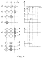
- FIG. 4 shows various operating states a) to f) for the grid times t1 to t3 and the associated ones Current pulses are shown, which are supplied to the heating element R4 at the raster time t1. Circles in the left part of the image indicate whether a printing process should be triggered at the raster times t1 to t3. An empty circle indicates that no printing process should be triggered, a hatched circle indicates that there is a printing requirement. In operating state a), no printing process is to be carried out for the raster times t1 to t3. No current pulse is supplied to the heating element R4 at the raster point in time t1. There is no preheating.
- a printing process should take place at raster time t3.
- a current pulse of constant intensity is supplied to it at the raster time t1.
- the energy content of the current pulse is set by its pulse width or duration.
- the current pulse is composed of partial pulses, each of which is a time interval T long.
- a current pulse of duration 2T composed of two partial pulses is accordingly generated and supplied to the heating element R4.
- a printing process should already be triggered at the raster time t1.
- a current pulse of duration 5T is supplied to the heating element R4.
- the heating element R4 is again subjected to a current pulse of duration 5T.
- the operating state of the heating element in which it continuously triggers printing processes, for example in order to produce a solid line on the recording medium, determines the maximum achievable printing speed of the print head 11. Since the duration of the current pulses for triggering printing processes is minimized by the method according to the invention, a high printing speed is achieved.
- the operating state of the adjacent heating elements R3 and R5, along the paths, is also taken into account when determining the energy content of the current pulse to be supplied to the heating element R4 36 and 40 (see FIG. 2) are arranged.
- the heating elements R3, R4 and R5 should each trigger a printing process. Since all three heating elements R3, R4, R5 are preheated and thus assume a higher preheating temperature than the ambient temperature Tu, less energy flows from the heating element R4 to the environment than without preheating the neighboring heating elements R3 and R5. The energy content of the current pulse to be supplied to the heating element R4 can be reduced by this amount.
- the heating element R4 is supplied with a current pulse of reduced duration 1T instead of a current pulse of duration 2T (cf. operating state b)) at raster time t1. The same happens if only one of the heating elements R3 or R4 is to trigger a printing process at raster time t3.
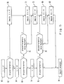
- a process flow for controlling the supply of the heating element R4 is shown schematically in a flowchart in FIG. 5. Such a procedure can e.g. by executing a program using the microprocessor 8 (see FIG. 1). In the method steps described in more detail below, the operating states shown in FIG. 4 are recognized and the associated current pulses are output
- method step 60 it is determined from the print data transmitted to print head 11 whether it is current Raster time t1 for the heating element R4 there is a pressure requirement. If this is the case, the method branches to step 66 in step 62. A partial pulse of duration 1T, ie a time interval T, is generated in this. Otherwise, proceed to method step 64. This analyzes whether there is a pressure requirement for the heating element R4 at the raster time t2. If the answer is affirmative, the method branches to step 70 in step 68 and determines whether one of the adjacent heating elements R3 or R5 or both should trigger a printing process. If this is the case, then a further partial pulse of duration 1T is generated in method step 72. Otherwise, method step 72 is omitted. In the subsequent method step 73, a partial pulse is again generated.
- step 74 It is then determined in method step 74 whether there is a pressure requirement for the heating element R4 at the raster point in time t3. If the result is positive, the method branches to step 78 in step 76. In this it is examined whether a printing process should be triggered simultaneously with the neighboring heating elements R3 or R5 or with both at raster time t3. If this is the case, a further partial pulse of duration 1T is generated in method step 80. Otherwise, step 80 is omitted and a partial pulse of duration 1T is generated in step 82.
- method step 84 If no pressure requirement has been determined in method step 76, a branch is made to method step 84 and the current pulse composed of the partial pulses generated in steps 66, 72, 73, 80 and 82 is output. This can last from 5T to 0T (empty pulse).
- Fig. 6 the control of the supply of heating elements according to the timing method is shown schematically in a block diagram.
- the heating elements of the print head 14 are electrically divided into two areas T1 and T2. They are fed with current pulses at different times via a multiplexer 92.
- the switch position of the multiplexer 92 is controlled by the microprocessor 8.
- a pulse generator 90 generates 8 current pulses depending on data from the microprocessor, which pulses are fed to the multiplexer 92.
- FIG. 7 shows the current profiles over time t for one heating element in each of the areas T1 and T2.
- the corresponding raster instants t1 and t2 are offset by 5 time intervals T, i.e. the duration of a current pulse to trigger a printing process. This results in a pulse-pause ratio or duty cycle of 50% for each area T1, T2. Since the pulse duration of a current pulse for triggering a printing process is minimal in the method according to the invention, the advantage of the high printing speed can be fully exploited when using the timing method.
Abstract
Description
Die Erfindung betrifft ein Verfahren zum Steuern der Speisung eines Thermodruck-Heizelements mit einer gemäß einem Druckraster geteilten Folge von Stromimpulsen, die bei Überschreiten eines vorgegebenen Energieinhalts einen Druckvorgang auslösen und bei Unterschreiten dieses Energieinhalts gegebenenfalls eine Vorheizung bewirken.The invention relates to a method for controlling the supply of a thermal pressure heating element with a sequence of current pulses divided according to a pressure pattern, which trigger a printing process when a predetermined energy content is exceeded and, if this energy content is undershot, possibly cause preheating.
Ein solches Verfahren wird beispielsweise bei einem Thermotransferdrucker eingesetzt, dessen Druckkopf mehrere in einer Reihe nebeneinander angeordnete Druckelemente hat. Zwischen dem Druckkopf und einem zu bedruckenden Aufzeichnungsträger ist ein wärmeempfindliches Farbband angeordnet, das bei punktueller Erwärmung durch ein Heizelement über eine Drucktemperatur hinaus einen Farbpunkt auf den Aufzeichnungsträger überträgt. Zwischen dem Druckkopf und dem Aufzeichnungsträger wird quer zur Linie der Druckelemente eine Relativbewegung erzeugt. In vorgegebenen Zeitabständen werden dann bestimmte Heizelemente mit Strom beaufschlagt und jeweils ein Druckvorgang ausgelöst. Der Aufzeichnungsträger wird somit rasterförmig mit Zeichen oder einem Bildmuster bedruckt.Such a method is used, for example, in a thermal transfer printer, the print head of which has a plurality of printing elements arranged side by side in a row. A heat-sensitive ink ribbon is arranged between the print head and a recording medium to be printed, which transfers a color dot to the recording medium when heated by a heating element above a printing temperature. Between the print head and the record carrier there is a relative movement transverse to the line of the print elements generated. Certain heating elements are then energized at predetermined intervals and a printing process is triggered in each case. The record carrier is thus printed in a grid pattern with characters or an image pattern.
Bei einem aus der DE 38 33 746 A1 bekannten Verfahren wird das jeweilige Heizelement vorgeheizt, wenn es keinen Druckvorgang auslöst. Hierzu werden dem Heizelement Stromimpulse zugeführt, deren jeweiliger Energieinhalt das Heizelement auf eine Temperatur unterhalb der Drucktemperatur aufheizt. Die Höhe und Dauer des Impulses kann abhängig von der herrschenden Umgebungstemperatur und der konstruktiven Ausgestaltung des Druckkopfes gesteuert werden. Dadurch wird erreicht, daß die Vorheiztemperatur gleichmäßig über den gesamten Druckkopfbereich verteilt ist.In a method known from
Bei dem bekannten Verfahren wird die je Heizelement zum Vorheizen zugeführte Energie unabhängig davon eingestellt, ob das betreffende Heizelement häufig oder selten Druckvorgänge auslöst. Da sich bei hoher Druckfrequenz am Heizelement eine höhere Temperatur einstellt als bei niedriger Druckfrequenz, muß die über den gesamten Druckkopf verteilte mittlere Vorheiztemperatur deutlich unterhalb der Drucktemperatur liegen, damit auch bei hoher Druckbeanspruchung des Heizelements ein einwandfreies Druckergebnis erzielt wird. Dies hat zur Folge, daß zum Auslösen eines Druckvorganges der dem Heizelement zugeführte Stromimpuls einen hohen Energieinhalt haben muß, damit das Heizelement auf seine Drucktemperatur aufgeheizt wird. Die Erzeugung solcher Stromimpulse ist technisch aufwendig, da der dazu erforderliche Stromimpulsgenerator eine hohe Spitzenbelastbarkeit haben muß.In the known method, the energy supplied to each heating element for preheating is set irrespective of whether the heating element in question triggers printing processes frequently or rarely. Since a higher temperature is set at the heating element than at a low pressure frequency, the mean preheating temperature distributed over the entire printhead must be significantly below the printing temperature, so that a perfect printing result is achieved even when the heating element is under high pressure. The consequence of this is that the current pulse supplied to the heating element must have a high energy content in order to trigger a printing process so that the heating element is heated to its printing temperature. The generation of such current pulses is technically complex since the current pulse generator required for this must have a high peak load capacity.
Hinzu kommt, daß bei einer großen Temperaturdifferenz zwischen Vorheiztemperatur und Drucktemperatur auch die Zeit für den Aufheizvorgang und die Abkühlzeit lang sind. Diese Zeiten beeinflussen die mit dem Druckverfahren erzielbare Druckgeschwindigkeit im erheblichen Maße. Da beim bekannten Verfahren zwischen der über den gesamten Druckkopfbereich gleichmäßig verteilten Vorheiztemperatur und der Drucktemperatur ein zum Erzielen der gewünschten Druckqualität hinreichend großer Temperaturabstand erforderlich ist, ist die erreichbare Druckgeschwindigkeit auf einen niedrigen Wert begrenzt.In addition, if there is a large temperature difference between the preheating temperature and the printing temperature, the time for the heating process and the cooling time are also long. These times have a considerable influence on the printing speed that can be achieved with the printing process. Since, in the known method, a sufficiently large temperature difference is required between the preheating temperature, which is uniformly distributed over the entire printhead area, and the printing temperature, the achievable printing speed is limited to a low value.
Es ist daher Aufgabe der Erfindung, ein Verfahren zum Steuern der Speisung eines Thermodruck-Heizelements anzugeben, mit dem eine hohe Druckgeschwindigkeit erreicht wird.It is therefore an object of the invention to provide a method for controlling the supply of a thermal pressure heating element with which a high printing speed is achieved.
Diese Aufgabe wird für eine Verfahren eingangs genannter Art dadurch gelöst, daß zu jedem Rasterzeitpunkt für eine vorbestimmte Zahl noch folgender Rasterzeitpunkte jeweils ein Druckerfordernis ermittelt wird, und daß für vor einem Rasterzeitpunkt mit Druckerfordernis liegende Rasterzeitpunkte ohne Druckerfordernis der Energieinhalt der Stromimpulse fortlaufend erhöht wird.This object is achieved for a method of the type mentioned above in that a printing requirement is determined for each raster point in time for a predetermined number of subsequent raster points in time, and in that for raster points in time before a raster point in time with printing requirement the energy content of the current pulses is continuously increased without a printing requirement.
Die Erfindung beruht auf der Überlegung, daß die Druckgeschwindigkeit maximal und die zum Auslösen eines Druckvorganges erforderliche Energie minimal wird, wenn das Heizelement möglichst bis nahe an seine Drucktemperatur vorgeheizt wird. Denn bei diesem Betriebszustand ist nur noch eine geringe zusätzliche Energie erforderlich, um den Druckvorgang auszulösen. Außerdem ist die Aufheizzeit sowie die Abkühlzeit des Heizelements dann kurz. Da das Heizelement je nach zu druckendem Muster über der Zeit unterschiedlich beansprucht wird, wird die ihm zugeführte Vorheizenergie erfindungsgemäß an sein Druckprogramm individuell angepaßt. Hierzu wird zu jedem Rasterzeitpunkt, in einer Vorschau ermittelt, ob zu nachfolgenden Rasterzeitpunkten jeweils ein Druck erfolgen soll. In diese Vorschau können beispielsweise die beiden nachfolgenden Rasterzeitpunkte einbezogen werden. Dadurch bleibt der Aufwand für die Verfahrensschritte der Vorschau gering. Wenn für die zukünftigen Rasterzeitpunkte kein Druckerfordernis vorliegt, so kann das Vorheizen auf ein Minimum beschränkt bleiben oder sogar völlig entfallen. Auf diese Weise ist die Vorheizenergie zur Vorbereitung eines Druckvorgangs nur dann aufzuwenden, wenn tatsächlich ein Druckauftrag vorliegt. Dies bedeutet, daß Energie eingespart wird.The invention is based on the consideration that the printing speed becomes maximum and the energy required to initiate a printing process becomes minimal if the heating element is preheated as close as possible to its printing temperature. Because in this operating state, only a little additional energy is required to trigger the printing process. In addition, the heating up and cooling down times of the heating element are then short. Since the heating element is subjected to different loads over time, depending on the pattern to be printed, the preheating energy supplied to it is increased according to the invention customized his printing program. For this purpose, a preview is determined at each raster point in time whether printing is to take place at subsequent raster points in time. For example, the following two raster times can be included in this preview. This means that the effort for the procedural steps of the preview remains low. If there is no printing requirement for the future grid times, then preheating can be kept to a minimum or even completely eliminated. In this way, the preheating energy for preparing a printing process can only be used when there is actually a print job. This means that energy is saved.
Wird bei der Vorschau festgestellt, daß in naher Zukunft vom Heizelement ein Druckvorgang ausgelöst werden soll, so wird zu dessen Vorbereitung das Heizelement zu Rasterzeitpunkten in denen es nicht druckt mit Stromimpulsen beaufschlagt. Deren Energieinhalt wird dann bis zum Rasterzeitpunkt, der vor dem Rasterzeitpunkt mit Druckerfordernis liegt, fortlaufend erhöht, so daß die Temperatur des Heizelement zum Rasterzeitpunkt, bei dem der Druckvorgang ausgelöst wird, kurz unterhalb der Drucktemperatur liegt. Zum Auslösen des Druckvorgangs muß dann der Stromimpuls nur noch einen geringen Energieinhalt haben, um die Temperatur des Heizelements von der Vorheiztemperatur auf die Drucktemperatur zu erhöhen. Die dafür erforderliche Zeit ist dann minimal, wodurch die Druckgeschwindigkeit innerhalb der Betriebsgrenzen des Thermodruckkopfes maximal wird. Da der Stromimpuls geringen Energieinhalt hat, ist auch seine elektrische Leistung klein, so daß der elektronische Aufwand zum Erzeugen des Stromimpulses überschaubar bleibt und eine kostengünstige Hardwarelösung für den Stromimpulsgenerator verwendet werden kann.If it is found in the preview that a printing process is to be triggered by the heating element in the near future, the heating element is subjected to current pulses at grid times in which it does not print in order to prepare it. The energy content of the heating element is then continuously increased until the raster time, which is before the raster time with printing requirements, so that the temperature of the heating element at the raster time at which the printing process is triggered is just below the printing temperature. To trigger the printing process, the current pulse then only has to have a low energy content in order to raise the temperature of the heating element from the preheating temperature to the printing temperature. The time required for this is then minimal, as a result of which the printing speed becomes maximum within the operating limits of the thermal print head. Since the current pulse has low energy content, its electrical output is also small, so that the electronic outlay for generating the current pulse remains manageable and an inexpensive hardware solution can be used for the current pulse generator.
Die Erhöhung des Energieinhalts der Stromimpulse während der Vorheizphase kann kontinuierlich erfolgen, beispielsweise indem der Gesamtenergiebetrag zum Erreichen der gewünschten Vorheiztemperatur berechnet wird und die Stromstärke und/oder die Dauer der Stromimpulse daran angepaßt werden.The energy content of the current pulses can be increased continuously during the preheating phase, for example by calculating the total energy amount to achieve the desired preheating temperature and adapting the current strength and / or the duration of the current pulses to it.
Eine bevorzugte Ausführungsform der Erfindung ist dadurch gekennzeichnet, daß die Erhöhung des Energieinhalts stufenweise erfolgt. Durch diese Maßnahme ist es möglich, das Verfahren auf einfache Weise an bekannte digitale Verfahren zum Steuern des Thermodruckkopfes anzupassen, bei denen die Speisung der Heizelemente bereits in diskreten, einstellbaren Stromstärken oder Impulsbreiten erfolgt.A preferred embodiment of the invention is characterized in that the energy content is increased in stages. This measure makes it possible to adapt the method in a simple manner to known digital methods for controlling the thermal print head, in which the heating elements are already supplied in discrete, adjustable current intensities or pulse widths.
Bei einer Weiterbildung der vorgenannten Ausführungsform haben die Stromimpulse eine konstante Stromstärke, wobei deren jeweilige Dauer fortlaufend verlängert wird. Die Dauer eines jeden Stromimpulses kann dabei aus gleichgroßen Zeitintervallen zusammengesetzt sein.In a development of the aforementioned embodiment, the current pulses have a constant current intensity, the respective duration of which is continuously extended. The duration of each current pulse can be composed of equally large time intervals.
Durch diese Maßnahmen wird es möglich, zur Speisung des Heizelements eine einfache Konstantstromquelle zu verwenden. Die Dauer oder Impulsbreite des Stromimpulses wird variiert, um dessen Energieinhalt zu verändern. Durch die Verwendung gleichgroßer Zeitintervalle kann bei der Realisierung der Impulserzeugung der Schaltungsaufwand weiter verringert werden, da die Stromimpulse aus einer Verknüpfung mit bereits vorhandenen Taktimpulsen einer Steuerzentrale abgeleitet werden können.These measures make it possible to use a simple constant current source to supply the heating element. The duration or pulse width of the current pulse is varied in order to change its energy content. By using equally large time intervals, the circuit complexity can be further reduced when realizing the pulse generation, since the current pulses can be derived from a link with already existing clock pulses of a control center.
Eine andere Ausführungsform ist dadurch gekennzeichnet, daß bei einem Thermodruckkopf mit mehreren nebeneinander angeordneten Heizelementen zu jedem Rasterzeitpunkt für eine vorbestimmte Zahl noch folgender Rasterzeitpunkte Druckerfordernisse ermittelt werden, und daß die Erhöhung des Energieinhalts der Stromimpulse des jeweiligen Heizelements gemindert wird, wenn ein Druckerfordernis eines ihm benachbarten Heizelements festgestellt wird.Another embodiment is characterized in that in the case of a thermal print head with a plurality of heating elements arranged next to one another at each raster time pressure requirements are determined for a predetermined number of subsequent grid times, and that the increase in the energy content of the current pulses of the respective heating element is reduced when a pressure requirement of a heating element adjacent to it is determined.
Bei dieser Ausführungsform wird der technische Effekt ausgenutzt, daß ein Teil der Wärme eines Heizelements zum benachbarten Heizelement übertragen wird. Wenn ein benachbartes Heizelement ebenfalls innerhalb des betrachteten Zeitraums einen Druckvorgang auslösen soll, und daher auf eine höhere Temperatur vorgeheizt wird, so muß der Energieteil, der von diesem Heizelement auf das jeweilige Heizelement übertragen wird, während der Vorheizphase nicht zugeführt werden. Der Energieinhalt der Stromimpulse kann dann um diesen Teil verringert werden. Dadurch wird eine noch günstigere Energieausnutzung erreicht.In this embodiment, the technical effect is exploited that part of the heat of one heating element is transferred to the adjacent heating element. If an adjacent heating element is also to trigger a printing process within the period under consideration and is therefore preheated to a higher temperature, the energy part which is transferred from this heating element to the respective heating element need not be supplied during the preheating phase. The energy content of the current pulses can then be reduced by this part. This results in an even more economical use of energy.
Gemäß einem weiteren bevorzugten Ausführungsbeispiel ist die Zeitlage der Stromimpulse in dem Rasterintervall von der Zeitlage der Stromimpulse für mindestens ein weiteres Heizelement verschieden. Diese Maßnahme läßt sich vorteilhaft einsetzen, wenn ein Thermodruckkopf mit sehr vielen Heizelementen, beispielsweise 256 oder 512, zum Drucken verwendet wird. Zum Beispiel beim Drucken von Postwertzeichen auf Briefumschläge in einer Frankiermaschine können derartige Thermodruckköpfe zum Einsatz kommen, da mit einer einzigen Vorschubbewegung eine sehr breite Textzeile gedruckt werden kann. Durch die Maßnahmen des vorgenannten Ausführungsbeispiels wird erreicht, daß die Heizelemente des Thermodruckkopfs in mindestens zwei Bereiche aufgeteilt werden können. Die Heizelemente des ersten Bereichs werden dann zu denen des zweiten Bereichs geringfügig zeitversetzt mit Stromimpulsen versorgt. Durch diese Zeitversetzung kann die den Heizelementen zuzuführende elektrische Leistung über die Zeit verteilt werden und die Spitzenbelastung der die Stromimpulse liefernden Stromquelle vermindert werden. Die Druckgeschwindigkeit muß dabei nicht herabgesetzt werden.According to a further preferred exemplary embodiment, the timing of the current pulses in the raster interval differs from the timing of the current pulses for at least one further heating element. This measure can be used advantageously if a thermal print head with a large number of heating elements, for example 256 or 512, is used for printing. For example, when printing postage stamps on envelopes in a franking machine, thermal print heads of this type can be used, since a very wide line of text can be printed with a single feed movement. The measures of the aforementioned embodiment ensure that the heating elements of the thermal print head can be divided into at least two areas. The heating elements of the first area will be then supplied with current pulses slightly delayed to those of the second region. As a result of this time offset, the electrical power to be supplied to the heating elements can be distributed over time and the peak load on the current source supplying the current pulses can be reduced. The printing speed does not have to be reduced.
Ausführungsbeispiele der Erfindung werden im folgenden an Hand der Zeichnungen erläutert. Darin zeigt,
- Fig. 1
- eine Frankiermaschine mit einem Thermotransferdruckwerk,
- Fig. 2
- eine schematische Darstellung eines Druckkopfes mit 5 Heizelementen,
- Fig. 3
- schematisch den Verlauf der Temperatur eines Heizelements während der Vorheiz- und der Druckphase über der Zeit,
- Fig. 4
- Stromimpulse für verschiedene Betriebszustände eines Heizelements,
- Fig. 5
- ein Ablaufschema zum Erzeugen eines Stromimpulses für ein Heizelement zu einem vorgegebenen Rasterzeitpunkt,
- Fig. 6
- ein Blockschaltbild einer Steuerung zum zeitversetzten Speisen zweier Heizelemente nach dem Multiplexverfahren, und
- Fig. 7
- die den Heizelementen nach Fig. 6 zugeführten Stromimpulse über der Zeit.
- Fig. 1
- a franking machine with a thermal transfer printing unit,
- Fig. 2
- a schematic representation of a printhead with 5 heating elements,
- Fig. 3
- schematically the course of the temperature of a heating element during the preheating and the printing phase over time,
- Fig. 4
- Current pulses for different operating states of a heating element,
- Fig. 5
- a flow diagram for generating a current pulse for a heating element at a predetermined raster time,
- Fig. 6
- a block diagram of a controller for staggered feeding two heating elements according to the multiplex method, and
- Fig. 7
- the current pulses supplied to the heating elements according to FIG. 6 over time.
In Fig. 1 sind in einer schematischen Darstellung wesentliche Komponenten einer Frankiermaschine dargestellt, für die die Erfindung verwendet wird. Auf der Außenseite eines Gehäuses 3 ist eine Anzeigeneinheit 1 und ein Tastaturenfeld 2 angeordnet. Ein von außen zugänglicher Gehäuseteil 4 nimmt eine Farbbandkassette (nicht dargestellt) für den Thermotransferdruck auf. Die zu bedruckenden Briefumschläge werden zwischen der Unterseite eines Druckkopfträgers 5 und einer Auflageplatte 6 hindurchbewegt, wobei während des Druckens Farbpartikel vom Farbband der Farbbandkassette auf die Briefumschläge übertragen werden.In Fig. 1, essential components of a franking machine are shown in a schematic representation, for which the invention is used. A
Rechts in Fig. 1 ist eine Steuerplatine 13 dargestellt, die einen Mikroprozessor 8, einen Arbeitsspeicher 7, einen Programmspeicher 9, eine serielle Schnittstelle 14, einen Druckkopfanschluß 16, eine Serviceschnittstelle 17, einen kundenspezifischen Festwertspeicher 12 sowie einen Netzteilanschluß 18 enthält.A
Im unteren Bildteil der Fig. 1 ist ein Druckwerk 10 schematisch dargestellt, das vom Druckkopfträger 5 gehalten wird. Das Druckwerk 10 enthält einen Thermotransfer-Druckkopf 11 sowie einen Transportmotor 21 zum Antreiben einer Transportrolle 22, die die Briefumschläge am Druckkopf 11 vorbei befördert.In the lower part of FIG. 1, a
In Fig. 2 ist der Druckkopf 11 schematisch dargestellt. Er hat auf der dem Farbband zugewandten Seite Heizelemente R1 bis R5, die nebeneinander in einer Reihe angeordnet und durch elektrische Widerstände gebildet sind. Zum Drucken wird zwischen einem Aufzeichnungsträger 30, beispielsweise einem Briefumschlag, und dem Druckkopf 11 eine Relativbewegung annähernd konstanter Geschwindigkeit erzeugt. Zu Rasterzeitpunkten t1 bis t5 mit gleichen Zeitabständen tp können durch die Heizelemente R1 bis R5 längs der Bahnen 32 bis 40 Druckvorgänge ausgelöst werden, bei denen Farbe des Farbbandes auf den Aufzeichnungsträger 30 übertragen werden, beispielsweise an den Stellen 42 bis 50.2, the
Die Fig. 2 zeigt lediglich schematisch das hier angewendete Druckprinzip. In der Realität besteht der Druckkopf 11 aus wesentlich mehr Heizelementen, beispielsweise aus 256 oder 512 Heizelementen, die in geringen Abständen nebeneinander angeordnet sind. Mithilfe eines solchen Druckkopfes kann mit einer einzigen Relativbewegung zwischen dem Aufzeichnungsträger 30 und dem Druckkopf 11 ein etwa 60 mm breiter Abschnitt bedruckt werden, wie es z.B. beim automatischen Frankieren von Briefumschlägen erforderlich ist.Fig. 2 shows only schematically the printing principle used here. In reality, the
Das erfindungsgemäße Verfahren zum Steuern der Speisung eines Heizelemts wird im folgenden an Hand des Heizelements R4, das gemäß Fig. 2 zum Rasterzeitpunkt t3 einen Druckvorgang auslösen soll, unter Bezugnahme auf Fig. 3 näher beschrieben. In dieser Figur ist im oberen Bildteil die Temperatur T über der Zeit t aufgetragen. Zum Rasterzeitpunkt t1 hat das Heizelement R4 eine Temperatur, die im wesentlichen der Umgebungstemperatur Tu entspricht. Gemäß der hier beschriebenen Ausführungsform der Erfindung werden drei Rasterzeitpunkte t1, t2 und t3 daraufhin untersucht, ob ein Druckvorgang ausgelöst werden soll. Hierbei wird festgestellt, daß zum Rasterzeitpunkt t3 ein solches Druckerfordernis vorhanden ist. Zu den Rasterzeitpunkt t1 und t2 wird nun das Heizelement R4 zur Vorbereitung des Druckvorgangs vorgeheizt, indem der Energieinhalt der dem elektrischen Widerstand des Heizelements R4 in den Zeitabständen tp zugeführten Stromimpulse I1 und I2 fortlaufend erhöht wird.The method according to the invention for controlling the supply of a heating element is described in more detail below with reference to FIG. 3 using the heating element R4, which is intended to trigger a printing process at raster time t3 in accordance with FIG. 2. In this figure, the temperature T is plotted over time t in the upper part of the figure. At the raster point in time t1, the heating element R4 has a temperature which essentially corresponds to the ambient temperature Tu. According to the embodiment of the invention described here, three raster times t1, t2 and t3 are examined to determine whether a printing process should be triggered. It is determined here that such a printing requirement is present at raster time t3. At grid times t1 and t2, heating element R4 is now preheated in preparation for the printing process by continuously increasing the energy content of current pulses I1 and I2 supplied to electrical resistance of heating element R4 at time intervals tp.
Im unteren Bildteil der Fig. 3 sind die zu den Zeitpunkten t1 bis t3 gehörenden Stromimpulse t1 bis t3 über der Zeit t dargestellt. Ihr jeweiliger Energieinhalt wird durch die Impulsdauer eingestellt. Der zum Rasterzeitpunkt t1 zugeführte Stromimpuls I1 bewirkt beim Heizelement R4 eine Temperaturerhöhung bis noch deutlich unterhalb der Grenztemperatur Tg, oberhalb der eine Farbübertragung vom wärmeempfindlichen Farbband auf den Aufzeichnungsträger 30 erfolgt, d.h. ein Druckvorgang ausgelöst wird. Aufgrund von Wärmeableitung an die Umgebung fällt die Temperatur bis zum Rasterzeitpunkt t2 wieder ab, bleibt jedoch deutlich oberhalb der Umgebungstemperatur Tu.In the lower part of FIG. 3, the current pulses t1 to t3 belonging to the times t1 to t3 are shown over the time t. Their respective energy content is set by the pulse duration. The current pulse I1 supplied at raster time t1 causes the heating element R4 to raise the temperature to well below the limit temperature Tg above which a color transfer from the heat-sensitive ink ribbon to the
Zum Rasterzeitpunkt t2 wird dem Heizelement R4 ein Stromimpuls I2 mit höherem Energieinhalt als der des Stromimpulses I1 zugeführt, so daß die Temperatur bis nahe an die Grenztemperatur Tg ansteigt. Wenn zum Rasterzeitpunkt t3 der Druckvorgang ausgelöst werden soll, so muß der Energieinhalt des entsprechenden Stromimpulses I3 nur noch geringfügig erhöht werden, damit die Grenztemperatur Tg überschritten wird. Es wird also beim Verfahren nach der Erfindung das Heizelement R4 bis nahe an die Grenztemperatur Tg vorgeheizt, so daß der eigentliche Stromimpuls I3 zum Auslösen des Druckvorgangs in seinem Energieinhalt und damit in seiner Dauer minimiert werden kann. Dadurch wird eine hohe Wiederholfrequenz des Druckvorgangs möglich und damit eine hohe Druckgeschwindigkeit erreicht.At raster time t2, the heating element R4 is supplied with a current pulse I2 with a higher energy content than that of the current pulse I1, so that the temperature rises to close to the limit temperature Tg. If the printing process is to be triggered at raster time t3, the energy content of the corresponding current pulse I3 only has to be increased slightly so that the limit temperature Tg is exceeded. Thus, in the method according to the invention, the heating element R4 is preheated to close to the limit temperature Tg, so that the actual current pulse I3 for triggering the printing process can be minimized in its energy content and thus in its duration. This enables a high repetition frequency of the printing process and thus a high printing speed.
In Fig. 4 sind verschiedene Betriebszustände a) bis f) für die Rasterzeitpunkte t1 bis t3 und die zugehörigen Stromimpulse dargestellt, die dem Heizelement R4 jeweils zum Rasterzeitpunkt t1 zugeführt werden. Im linken Bildteil ist durch Kreise angezeigt, ob zu den Rasterzeitpunkten t1 bis t3 ein Druckvorgang ausgelöst werden soll. Ein leerer Kreis kennzeichnet hierbei, daß kein Druckvorgang ausgelöst werden soll, ein schraffierter Kreis, daß ein Druckerfordernis vorliegt. Im Betriebszustand a) ist für die Rasterzeitpunkt t1 bis t3 kein Druckvorgang auszuführen. Dem Heizelement R4 wird zum Rasterzeitpunkt t1 kein Stromimpuls zugeführt. Ein Vorheizen findet nicht statt.4 shows various operating states a) to f) for the grid times t1 to t3 and the associated ones Current pulses are shown, which are supplied to the heating element R4 at the raster time t1. Circles in the left part of the image indicate whether a printing process should be triggered at the raster times t1 to t3. An empty circle indicates that no printing process should be triggered, a hatched circle indicates that there is a printing requirement. In operating state a), no printing process is to be carried out for the raster times t1 to t3. No current pulse is supplied to the heating element R4 at the raster point in time t1. There is no preheating.
Im Betriebszustand b) soll zum Rasterzeitpunkt t3 ein Druckvorgang erfolgen. Um das Heizelement R4 hinreichend vorzuheizen, wird diesem zum Rasterzeitpunkt t1 ein Stromimpuls konstanter Stärke zugeführt. Der Energieinhalt des Stromimpulses wird durch dessen Impulsbreite oder Dauer eingestellt. Hierzu wird der Stromimpuls aus Teilimpulsen, die jeweils ein Zeitintervall T lang sind, zusammengesetzt. Beim Betriebszustand b) wird demgemäß ein aus zwei Teilimpulsen zusammengesetzter Stromimpuls der Dauer 2T erzeugt und dem Heizelement R4 zugeführt.In operating state b), a printing process should take place at raster time t3. In order to preheat the heating element R4 sufficiently, a current pulse of constant intensity is supplied to it at the raster time t1. The energy content of the current pulse is set by its pulse width or duration. For this purpose, the current pulse is composed of partial pulses, each of which is a time interval T long. In operating state b), a current pulse of
Im Betriebszustand c) liegt ein Druckerfordernis zum Rasterzeitpunkt t2 vor. Zum Vorheizen auf einen Temperaturwert knapp unterhalb der Grenztemperatur Tg ist ein erhöhter Energieinhalt des Stromimpulses erforderlich, der durch Verlängern der Impulsdauer auf vier Zeitintervalle T realisiert wird.In operating state c) there is a printing requirement at raster time t2. To preheat to a temperature value just below the limit temperature Tg, an increased energy content of the current pulse is required, which is realized by extending the pulse duration to four time intervals T.
Im Betriebszustand d) soll bereits zum Rasterzeitpunkt t1 ein Druckvorgang ausgelöst werden. Um die erforderliche Grenztemperatur Tg zu überschreiten, wird dem Heizelement R4 ein Stromimpuls der Dauer 5T zugeführt. Wenn im darauffolgenden Rasterzeitpunkt t2 wiederum ein Druckvorgang ausgeführt werden soll (in der Figur nicht dargestellt), so wird das Heizelement R4 nochmals mit einem Stromimpuls der Dauer 5T beaufschlagt. Der Betriebszustand des Heizelements, bei dem es fortlaufend Druckvorgänge auslöst, beispielsweise um eine durchgezogene Linie auf dem Aufzeichnungsträger zu erzeugen, legt die maximal erreichbare Druckgeschwindigkeit des Druckkopfes 11 fest. Da die Dauer der Stromimpulse zum Auslösen von Druckvorgängen durch das Verfahren nach der Erfindung minimiert wird, wird eine hohe Druckgeschwindigkeit erzielt.In the operating state d), a printing process should already be triggered at the raster time t1. In order to exceed the required limit temperature Tg, a current pulse of
Um die Energieinhalte der Stromimpulse festzulegen, wurden bei diesem Beispiel lediglich 3 Rasterzeitpunkte t1 bis t3 betrachtet und der Stromimpuls zum Auslösen eines Druckvorgangs auf 5 Zeitintervalle T festgelegt. In der Praxis hat es sich gezeigt, daß damit bereits ein erheblicher Fortschritt hinsichtlich der Druckgeschwindigkeit erreicht wird, ohne daß der Rechenaufwand zum Ermitteln der Druckerfordernisse und der Hardwareaufwand zum individuellen Vorheizen des Heizelements R4 groß ist. Es ist leicht einzusehen, daß die Einbeziehung weiterer Rasterzeitpunkte in die Vorausschau sowie eine feinere Abstufung der Impulsdauer durch eine höhere Zahl von Teilimpulsen eine noch bessere Ausnutzung des Potentials zur Erhöung der Druckgeschwindigkeit innerhalb der Betriebsgrenzen eines Druckkopfes ermöglicht.To determine the energy content of the current pulses, only 3 raster times t1 to t3 were considered in this example and the current pulse for triggering a printing process was set to 5 time intervals T. In practice, it has been shown that a considerable advance in printing speed is already achieved without the computing effort for determining the printing requirements and the hardware expenditure for individually preheating the heating element R4 being great. It is easy to see that the inclusion of further raster times in the preview and a finer gradation of the pulse duration through a higher number of partial pulses enables an even better use of the potential for increasing the printing speed within the operating limits of a print head.
Im Betriebszustand e) wird beim Festlegen des Energieinhalts des dem Heizelements R4 zuzuführenden Stromimpulses auch der Betriebszustand der benachbarten Heizelemente R3 und R5 berücksichtigt, die längs der Bahnen 36 und 40 (vgl. Fig. 2) angeordnet sind. Zum Rasterzeitpunkt t3 sollen die Heizelemente R3, R4 und R5 jeweils einen Druckvorgang auslösen. Da alle drei Heizelemente R3, R4, R5 vorgeheizt werden und damit eine gegenüber der Umgebungstemperatur Tu höhere Vorheiztemperatur annehmen, fließt vom Heizelement R4 weniger Energie an die Umgebung ab, als ohne Vorheizung der benachbarten Heizelemente R3 und R5. Um diesen Betrag kann der Energieinhalt des Stromimpulses verringert werden, der dem Heizelement R4 zuzuführen ist. Daher wird dem Heizelement R4 zum Rasterzeitpunkt t1 an Stelle eines Stromimpulses der Dauer 2T (vgl. Betriebszustand b)) ein Stromimpuls mit verringerter Dauer 1T zugeführt. Gleiches geschieht, wenn nur eines der Heizelemente R3 oder R4 zum Rasterzeitpunkt t3 einen Druckvorgang auslösen soll.In the operating state e), the operating state of the adjacent heating elements R3 and R5, along the paths, is also taken into account when determining the energy content of the current pulse to be supplied to the
Im Betriebszustand f) liegt zum Rasterzeitpunkt t2 ein Druckerfordernis vor. Für diesen Betriebszustand wird die Dauer des dem Heizelement R4 zum Rasterzeitpunkt t1 zugeführten Stromimpulses auf 3T festgelegt. In gleicher Weise wird vorgegangen, wenn nur eines der Heizelemente R3 oder R4 zum Rasterzeitpunkt t2 einen Druckvorgang auslösen soll.In operating state f) there is a print requirement at raster time t2. For this operating state, the duration of the current pulse supplied to the heating element R4 at the raster time t1 is set to 3T. The same procedure is followed if only one of the heating elements R3 or R4 is to trigger a printing process at raster time t2.
In Fig. 5 ist in einem Flußdiagramm schematisch ein Verfahrensablauf zum Steuern der Speisung des Heizelements R4 dargestellt. Ein solcher Verfahrensablauf kann z.B. durch Abarbeiten eines Programms mithilfe des Mikroprozessors 8 (vgl. Fig. 1) realisiert werden. Bei den nachfolgend näher beschriebenen Verfahrensschritten werden die in der Fig. 4 gezeigten Betriebszustände erkannt und die dazugehörigen Stromimpulse ausgegebenA process flow for controlling the supply of the heating element R4 is shown schematically in a flowchart in FIG. 5. Such a procedure can e.g. by executing a program using the microprocessor 8 (see FIG. 1). In the method steps described in more detail below, the operating states shown in FIG. 4 are recognized and the associated current pulses are output
Im Verfahrensschritt 60 wird aus den an den Druckkopf 11 übertragenen Druckdaten ermittelt, ob zum aktuellen Rasterzeitpunkt t1 für das Heizelement R4 ein Druckerfordernis vorliegt. Ist dies der Fall, so wird im Verfahrensschritt 62 zum Verfahrensschritt 66 verzweigt. In diesem wird ein Teilimpuls der Dauer 1T, d.h. ein Zeitintervall T, erzeugt. Andernfalls wird zum Verfahrensschritt 64 weitergegangen. In diesem wird analysiert, ob zum Rasterzeitpunkt t2 ein Druckerfordernis für das Heizelement R4 vorliegt. Bei Bejahung wird im Verfahrensschritt 68 zum Schritt 70 verzweigt und ermittelt, ob eines der benachbarten Heizelemente R3 bzw. R5 oder beide einen Druckvorgang auslösen sollen. Wenn dies zutrifft, so wird im Verfahrensschritt 72 ein weiterer Teilimpuls der Dauer 1T erzeugt. Andernfalls wird der Verfahrensschritt 72 ausgelassen. Im nachfolgenden Verfahrensschritt 73 wird wiederum ein Teilimpuls erzeugt.In
Anschließend wird im Verfahrensschritt 74 ermittelt, ob zum Rasterzeitpunkt t3 für das Heizelement R4 ein Druckerfordernis vorliegt. Bei positivem Ergebnis wird im Verfahrensschritt 76 zu Schritt 78 verzweigt. In diesem wird untersucht, ob zum Rasterzeitpunkt t3 bei den benachbarten Heizelementen R3 bzw. R5 oder bei beiden gleichzeitig ein Druckvorgang ausgelöst werden soll. Ist dies der Fall, so wird im Verfahrensschritt 80 ein weiterer Teilimpuls der Dauer 1T erzeugt. Andernfalls wird der Verfahrensschritt 80 ausgelassen und in Schritt 82 ein Teilimpuls der Dauer 1T generiert.It is then determined in
Falls im Verfahrensschritt 76 kein Druckerfordernis festgestellt worden ist, wird zum Verfahrensschritt 84 verzweigt und der aus den in den Schritten 66, 72, 73, 80 und 82 erzeugten Teilimpulse zusammengesetzte Stromimpuls ausgegeben. Dieser kann eine Dauer von 5T bis 0T (Leerimpuls) haben.If no pressure requirement has been determined in
In Fig. 6 ist in einem Blockschaltbild schematisch die Steuerung der Speisung von Heizelementen nach dem Zeitlageverfahren dargestellt. Die Heizelemente des Druckkopfes 14 sind hierbei elektrisch in zwei Bereiche T1 und T2 aufgeteilt. Sie werden über einen Multiplexer 92 zeitlich versetzt mit Stromimpulsen gespeist. Die Schalterstellung des Multiplexers 92 wird vom Mikroprozessor 8 gesteuert. Ein Impulsgenerator 90 erzeugt abhängig von Daten des Mikroprozessors 8 Stromimpulse, die dem Multiplexer 92 zugeführt werden. Durch die Anwendung des Zeitlageverfahrens wird es möglich eine große Zahl von Heizelementen eines Druckkopfes 11, beispielsweise 512 Heizelemente, mit einem elektrisch einfach aufgebauten Stromimpulsgenerator 90 zu speisen, da dessen Spitzenstrombelastung durch die Zeitverlagerung reduziert wird.In Fig. 6, the control of the supply of heating elements according to the timing method is shown schematically in a block diagram. The heating elements of the
In Fig. 7 sind die Stromverläufe über der Zeit t für je ein Heizelement der Bereiche T1 und T2 dargestellt. Wie der Fig. zu entnehmen ist, sind jeweils die einander entsprechenden Rasterzeitpunkte t1 bzw. t2 zueinander um 5 Zeitintervalle T versetzt, d.h. um die Dauer eines Stromimpulses zum Auslösen eines Druckvorgangs. Dadurch ergibt sich für jeden Bereicht T1, T2 ein Impuls-Pausenverhältnis oder Tastverhältnis von 50 %. Da die Impulsdauer eines Stromimpulses zum Auslösen eines Druckvorgangs beim Verfahren nach der Erfindung minimal ist, kann bei der Anwendung des Zeitlageverfahrens der Vorteil der hohen Druckgeschwindigkeit voll genutzt werden.7 shows the current profiles over time t for one heating element in each of the areas T1 and T2. As can be seen from the figure, the corresponding raster instants t1 and t2 are offset by 5 time intervals T, i.e. the duration of a current pulse to trigger a printing process. This results in a pulse-pause ratio or duty cycle of 50% for each area T1, T2. Since the pulse duration of a current pulse for triggering a printing process is minimal in the method according to the invention, the advantage of the high printing speed can be fully exploited when using the timing method.
Claims (11)
Applications Claiming Priority (2)
| Application Number | Priority Date | Filing Date | Title |
|---|---|---|---|
| DE4133207A DE4133207A1 (en) | 1991-10-07 | 1991-10-07 | METHOD FOR CONTROLLING THE SUPPLY OF A THERMAL PRINT HEATING ELEMENT |
| DE4133207 | 1991-10-07 |
Publications (3)
| Publication Number | Publication Date |
|---|---|
| EP0536526A2 true EP0536526A2 (en) | 1993-04-14 |
| EP0536526A3 EP0536526A3 (en) | 1993-05-26 |
| EP0536526B1 EP0536526B1 (en) | 1997-01-22 |
Family
ID=6442201
Family Applications (1)
| Application Number | Title | Priority Date | Filing Date |
|---|---|---|---|
| EP92114645A Expired - Lifetime EP0536526B1 (en) | 1991-10-07 | 1992-08-27 | Supply control for a heating element in a thermal printer |
Country Status (4)
| Country | Link |
|---|---|
| US (1) | US5453776A (en) |
| EP (1) | EP0536526B1 (en) |
| CA (1) | CA2078182C (en) |
| DE (2) | DE4133207A1 (en) |
Cited By (3)
| Publication number | Priority date | Publication date | Assignee | Title |
|---|---|---|---|---|
| DE4405134A1 (en) * | 1994-02-18 | 1995-09-07 | F & O Elektronic Systems Gmbh | Heating resistance control device for thermal process printer |
| EP1661716A2 (en) | 2004-11-30 | 2006-05-31 | Francotyp-Postalia GmbH | Method of driving a thermal transfer print head |
| US7256804B2 (en) | 2004-06-03 | 2007-08-14 | Francotyp-Postalia Gmbh | Arrangement and method for activation of a thermotransfer print head |
Families Citing this family (6)
| Publication number | Priority date | Publication date | Assignee | Title |
|---|---|---|---|---|
| DE29504576U1 (en) * | 1995-03-07 | 1995-05-11 | Francotyp Postalia Gmbh | Print head thermal control |
| GB9801743D0 (en) | 1998-01-28 | 1998-03-25 | Neopost Ltd | Digital print head data registration |
| US6476838B1 (en) | 1999-09-03 | 2002-11-05 | Oki Data America, Inc. | Method of driving a thermal print head |
| DE102005007220B4 (en) * | 2005-02-15 | 2007-08-16 | Francotyp-Postalia Gmbh | Method and arrangement for controlling the printing of a thermal transfer printing device |
| JP5180061B2 (en) * | 2005-04-06 | 2013-04-10 | ズィンク イメージング エルエルシー | Multicolor thermal imaging method and thermal printer |
| DE102006009334A1 (en) | 2006-03-01 | 2007-09-20 | Francotyp-Postalia Gmbh | A process for improving the quality of printing with a thermal transfer printhead and apparatus for carrying out the process |
Citations (6)
| Publication number | Priority date | Publication date | Assignee | Title |
|---|---|---|---|---|
| JPS6067178A (en) * | 1983-09-22 | 1985-04-17 | Fuji Xerox Co Ltd | Driver for thermal head |
| JPS61239966A (en) * | 1985-04-18 | 1986-10-25 | Fuji Xerox Co Ltd | Apparatus for driving thermal head |
| JPS634970A (en) * | 1986-06-26 | 1988-01-09 | Shinko Electric Co Ltd | Heating-driving method for thermal line printer head |
| EP0329369A2 (en) * | 1988-02-15 | 1989-08-23 | Shinko Denki Kabushiki Kaisha | Method and apparatus for energizing thermal head of a thermal printer |
| WO1989009382A1 (en) * | 1988-03-21 | 1989-10-05 | Kroy Inc. | Pixel preheat and automated thermal transfer system |
| JPH0361053A (en) * | 1989-07-31 | 1991-03-15 | Canon Inc | Recorder |
Family Cites Families (3)
| Publication number | Priority date | Publication date | Assignee | Title |
|---|---|---|---|---|
| US4820653A (en) * | 1988-02-12 | 1989-04-11 | American Telephone And Telegraph Company | Technique for fabricating complementary dielectrically isolated wafer |
| DE3833746A1 (en) * | 1988-09-30 | 1990-04-05 | Siemens Ag | Thermal printing with pre-heating resistor elements - energised by actual data and by clock pulse of variable width and height |
| JPH0667179A (en) * | 1992-06-19 | 1994-03-11 | Canon Inc | Back light device, display device and display system using the same |
-
1991
- 1991-10-07 DE DE4133207A patent/DE4133207A1/en not_active Withdrawn
-
1992
- 1992-08-25 US US07/935,842 patent/US5453776A/en not_active Expired - Lifetime
- 1992-08-27 EP EP92114645A patent/EP0536526B1/en not_active Expired - Lifetime
- 1992-08-27 DE DE59207937T patent/DE59207937D1/en not_active Expired - Lifetime
- 1992-09-14 CA CA002078182A patent/CA2078182C/en not_active Expired - Lifetime
Patent Citations (6)
| Publication number | Priority date | Publication date | Assignee | Title |
|---|---|---|---|---|
| JPS6067178A (en) * | 1983-09-22 | 1985-04-17 | Fuji Xerox Co Ltd | Driver for thermal head |
| JPS61239966A (en) * | 1985-04-18 | 1986-10-25 | Fuji Xerox Co Ltd | Apparatus for driving thermal head |
| JPS634970A (en) * | 1986-06-26 | 1988-01-09 | Shinko Electric Co Ltd | Heating-driving method for thermal line printer head |
| EP0329369A2 (en) * | 1988-02-15 | 1989-08-23 | Shinko Denki Kabushiki Kaisha | Method and apparatus for energizing thermal head of a thermal printer |
| WO1989009382A1 (en) * | 1988-03-21 | 1989-10-05 | Kroy Inc. | Pixel preheat and automated thermal transfer system |
| JPH0361053A (en) * | 1989-07-31 | 1991-03-15 | Canon Inc | Recorder |
Non-Patent Citations (4)
| Title |
|---|
| PATENT ABSTRACTS OF JAPAN vol. 11, no. 86 (M-572)(2533) 17. Maerz 1987 & JP-A-61 239 966 ( FUJI XEROX CO LTD ) 25. October 1986 * |
| PATENT ABSTRACTS OF JAPAN vol. 12, no. 197 (M-706)(3044) 8. Juni 1988 & JP-A-63 004 970 ( SHINKO ELECTRIC CO LTD ) 09. January 1988 * |
| PATENT ABSTRACTS OF JAPAN vol. 15, no. 215 (M-1119)31. Mai 1991 & JP-A-3 061 053 ( CANON INC ) 15. Maerz 1991 * |
| PATENT ABSTRACTS OF JAPAN vol. 9, no. 206 (M-406)(1929) 23. August 1985 & JP-A-60 067 178 ( FUJI XEROX K.K. ) 17. April 1985 * |
Cited By (4)
| Publication number | Priority date | Publication date | Assignee | Title |
|---|---|---|---|---|
| DE4405134A1 (en) * | 1994-02-18 | 1995-09-07 | F & O Elektronic Systems Gmbh | Heating resistance control device for thermal process printer |
| DE4405134C2 (en) * | 1994-02-18 | 1999-07-08 | F & O Elektronic Systems Gmbh | Device and method for controlling the heating resistors of a thermal printing board for printing gray and / or color levels |
| US7256804B2 (en) | 2004-06-03 | 2007-08-14 | Francotyp-Postalia Gmbh | Arrangement and method for activation of a thermotransfer print head |
| EP1661716A2 (en) | 2004-11-30 | 2006-05-31 | Francotyp-Postalia GmbH | Method of driving a thermal transfer print head |
Also Published As
| Publication number | Publication date |
|---|---|
| DE4133207A1 (en) | 1993-04-15 |
| DE59207937D1 (en) | 1997-03-06 |
| CA2078182C (en) | 1998-08-04 |
| US5453776A (en) | 1995-09-26 |
| CA2078182A1 (en) | 1993-04-08 |
| EP0536526A3 (en) | 1993-05-26 |
| EP0536526B1 (en) | 1997-01-22 |
Similar Documents
| Publication | Publication Date | Title |
|---|---|---|
| DE2540686C2 (en) | Battery operated printer | |
| DE3311735C2 (en) | ||
| DE3235759C2 (en) | ||
| EP0331138B1 (en) | Printer | |
| EP0352698B1 (en) | Method for producing information concerning a type of print head | |
| DE3641435A1 (en) | METHOD AND DEVICE FOR TEMPERATURE CONTROL OF THERMAL PRINTERS | |
| DE3315257C2 (en) | Thermal printer | |
| DE2848910A1 (en) | DRIVE SYSTEM FOR CONTROLLING THE MOVEMENT OF A LIMB | |
| DE2937716C2 (en) | ||
| DE4438600B4 (en) | thermal printer | |
| DE3447511A1 (en) | METHOD FOR RECORDING BY MEANS OF A THERMAL PRINTER AND DEVICE THEREFOR | |
| EP0536526B1 (en) | Supply control for a heating element in a thermal printer | |
| DE60122937T2 (en) | Thermal print head controller | |
| DE2062494C3 (en) | Thermal print head | |
| DE2714482B2 (en) | Control arrangement for thermal recorder | |
| DE2825620C2 (en) | Method and apparatus for printing dot matrix characters by a printhead | |
| DE60207488T2 (en) | Method and device for controlling a heating element in a thermal head | |
| DE2648828C3 (en) | Device for operating electromagnets | |
| EP1661716B1 (en) | Method of driving a thermal transfer print head | |
| DE3628191A1 (en) | Method and device for recording information on an information carrier by means of a thermal print head | |
| DE2633978B1 (en) | Method and circuit arrangement for intermediate point printing in dot printers | |
| DE3507335C2 (en) | ||
| EP1661717B1 (en) | Method for controlling a thermal transfer printhead | |
| EP0575668B1 (en) | Drive circuit for an electrothermal recorder with resistive ribbon | |
| EP0444763B1 (en) | Thermal printer taking heating element history into account |
Legal Events
| Date | Code | Title | Description |
|---|---|---|---|
| PUAI | Public reference made under article 153(3) epc to a published international application that has entered the european phase |
Free format text: ORIGINAL CODE: 0009012 |
|
| PUAL | Search report despatched |
Free format text: ORIGINAL CODE: 0009013 |
|
| AK | Designated contracting states |
Kind code of ref document: A2 Designated state(s): AT BE CH DE DK ES FR GB GR IE IT LI LU MC NL PT SE |
|
| AK | Designated contracting states |
Kind code of ref document: A3 Designated state(s): AT BE CH DE DK ES FR GB GR IE IT LI LU MC NL PT SE |
|
| RBV | Designated contracting states (corrected) |
Designated state(s): CH DE FR GB IT LI |
|
| 17P | Request for examination filed |
Effective date: 19930513 |
|
| 17Q | First examination report despatched |
Effective date: 19930915 |
|
| RAP1 | Party data changed (applicant data changed or rights of an application transferred) |
Owner name: FRANCOTYP-POSTALIA GMBH |
|
| GRAG | Despatch of communication of intention to grant |
Free format text: ORIGINAL CODE: EPIDOS AGRA |
|
| GRAH | Despatch of communication of intention to grant a patent |
Free format text: ORIGINAL CODE: EPIDOS IGRA |
|
| RAP1 | Party data changed (applicant data changed or rights of an application transferred) |
Owner name: FRANCOTYP-POSTALIA AKTIENGESELLSCHAFT & CO. |
|
| GRAH | Despatch of communication of intention to grant a patent |
Free format text: ORIGINAL CODE: EPIDOS IGRA |
|
| GRAA | (expected) grant |
Free format text: ORIGINAL CODE: 0009210 |
|
| AK | Designated contracting states |
Kind code of ref document: B1 Designated state(s): CH DE FR GB IT LI |
|
| REG | Reference to a national code |
Ref country code: CH Ref legal event code: EP |
|
| REG | Reference to a national code |
Ref country code: CH Ref legal event code: NV Representative=s name: ROTTMANN, ZIMMERMANN + PARTNER AG |
|
| ET | Fr: translation filed | ||
| REF | Corresponds to: |
Ref document number: 59207937 Country of ref document: DE Date of ref document: 19970306 |
|
| GBT | Gb: translation of ep patent filed (gb section 77(6)(a)/1977) |
Effective date: 19970314 |
|
| ITF | It: translation for a ep patent filed |
Owner name: 0508;07MIFSTUDIO JAUMANN |
|
| PLBE | No opposition filed within time limit |
Free format text: ORIGINAL CODE: 0009261 |
|
| STAA | Information on the status of an ep patent application or granted ep patent |
Free format text: STATUS: NO OPPOSITION FILED WITHIN TIME LIMIT |
|
| 26N | No opposition filed | ||
| REG | Reference to a national code |
Ref country code: GB Ref legal event code: IF02 |
|
| REG | Reference to a national code |
Ref country code: CH Ref legal event code: PFA Owner name: FRANCOTYP-POSTALIA AKTIENGESELLSCHAFT & CO. Free format text: FRANCOTYP-POSTALIA AKTIENGESELLSCHAFT & CO.#TRIFTWEG 21-26#16547 BIRKENWERDER (DE) -TRANSFER TO- FRANCOTYP-POSTALIA AKTIENGESELLSCHAFT & CO.#TRIFTWEG 21-26#16547 BIRKENWERDER (DE) |
|
| PGFP | Annual fee paid to national office [announced via postgrant information from national office to epo] |
Ref country code: CH Payment date: 20110824 Year of fee payment: 20 |
|
| PGFP | Annual fee paid to national office [announced via postgrant information from national office to epo] |
Ref country code: GB Payment date: 20110819 Year of fee payment: 20 Ref country code: DE Payment date: 20110614 Year of fee payment: 20 Ref country code: FR Payment date: 20110901 Year of fee payment: 20 |
|
| PGFP | Annual fee paid to national office [announced via postgrant information from national office to epo] |
Ref country code: IT Payment date: 20110824 Year of fee payment: 20 |
|
| REG | Reference to a national code |
Ref country code: DE Ref legal event code: R071 Ref document number: 59207937 Country of ref document: DE |
|
| REG | Reference to a national code |
Ref country code: DE Ref legal event code: R071 Ref document number: 59207937 Country of ref document: DE |
|
| REG | Reference to a national code |
Ref country code: CH Ref legal event code: PL |
|
| REG | Reference to a national code |
Ref country code: GB Ref legal event code: PE20 Expiry date: 20120826 |
|
| PG25 | Lapsed in a contracting state [announced via postgrant information from national office to epo] |
Ref country code: DE Free format text: LAPSE BECAUSE OF EXPIRATION OF PROTECTION Effective date: 20120828 Ref country code: GB Free format text: LAPSE BECAUSE OF EXPIRATION OF PROTECTION Effective date: 20120826 |