EP0536440A1 - H.F. surgical instrument for cutting and coagulating - Google Patents
H.F. surgical instrument for cutting and coagulating Download PDFInfo
- Publication number
- EP0536440A1 EP0536440A1 EP91117332A EP91117332A EP0536440A1 EP 0536440 A1 EP0536440 A1 EP 0536440A1 EP 91117332 A EP91117332 A EP 91117332A EP 91117332 A EP91117332 A EP 91117332A EP 0536440 A1 EP0536440 A1 EP 0536440A1
- Authority
- EP
- European Patent Office
- Prior art keywords
- sleeve
- electrode
- instrument according
- instrument
- face
- Prior art date
- Legal status (The legal status is an assumption and is not a legal conclusion. Google has not performed a legal analysis and makes no representation as to the accuracy of the status listed.)
- Granted
Links
Images


Classifications
-
- A—HUMAN NECESSITIES
- A61—MEDICAL OR VETERINARY SCIENCE; HYGIENE
- A61B—DIAGNOSIS; SURGERY; IDENTIFICATION
- A61B18/00—Surgical instruments, devices or methods for transferring non-mechanical forms of energy to or from the body
- A61B18/04—Surgical instruments, devices or methods for transferring non-mechanical forms of energy to or from the body by heating
- A61B18/12—Surgical instruments, devices or methods for transferring non-mechanical forms of energy to or from the body by heating by passing a current through the tissue to be heated, e.g. high-frequency current
- A61B18/14—Probes or electrodes therefor
- A61B18/1485—Probes or electrodes therefor having a short rigid shaft for accessing the inner body through natural openings
-
- A—HUMAN NECESSITIES
- A61—MEDICAL OR VETERINARY SCIENCE; HYGIENE
- A61B—DIAGNOSIS; SURGERY; IDENTIFICATION
- A61B18/00—Surgical instruments, devices or methods for transferring non-mechanical forms of energy to or from the body
- A61B18/04—Surgical instruments, devices or methods for transferring non-mechanical forms of energy to or from the body by heating
- A61B18/12—Surgical instruments, devices or methods for transferring non-mechanical forms of energy to or from the body by heating by passing a current through the tissue to be heated, e.g. high-frequency current
- A61B18/14—Probes or electrodes therefor
- A61B18/1402—Probes for open surgery
-
- A—HUMAN NECESSITIES
- A61—MEDICAL OR VETERINARY SCIENCE; HYGIENE
- A61B—DIAGNOSIS; SURGERY; IDENTIFICATION
- A61B18/00—Surgical instruments, devices or methods for transferring non-mechanical forms of energy to or from the body
- A61B18/04—Surgical instruments, devices or methods for transferring non-mechanical forms of energy to or from the body by heating
- A61B18/12—Surgical instruments, devices or methods for transferring non-mechanical forms of energy to or from the body by heating by passing a current through the tissue to be heated, e.g. high-frequency current
- A61B18/14—Probes or electrodes therefor
- A61B18/148—Probes or electrodes therefor having a short, rigid shaft for accessing the inner body transcutaneously, e.g. for neurosurgery or arthroscopy
-
- A—HUMAN NECESSITIES
- A61—MEDICAL OR VETERINARY SCIENCE; HYGIENE
- A61B—DIAGNOSIS; SURGERY; IDENTIFICATION
- A61B18/00—Surgical instruments, devices or methods for transferring non-mechanical forms of energy to or from the body
- A61B2018/00053—Mechanical features of the instrument of device
- A61B2018/00184—Moving parts
- A61B2018/00196—Moving parts reciprocating lengthwise
-
- A—HUMAN NECESSITIES
- A61—MEDICAL OR VETERINARY SCIENCE; HYGIENE
- A61B—DIAGNOSIS; SURGERY; IDENTIFICATION
- A61B2218/00—Details of surgical instruments, devices or methods for transferring non-mechanical forms of energy to or from the body
- A61B2218/001—Details of surgical instruments, devices or methods for transferring non-mechanical forms of energy to or from the body having means for irrigation and/or aspiration of substances to and/or from the surgical site
- A61B2218/002—Irrigation
- A61B2218/006—Irrigation for smoke evacuation
-
- A—HUMAN NECESSITIES
- A61—MEDICAL OR VETERINARY SCIENCE; HYGIENE
- A61B—DIAGNOSIS; SURGERY; IDENTIFICATION
- A61B2218/00—Details of surgical instruments, devices or methods for transferring non-mechanical forms of energy to or from the body
- A61B2218/001—Details of surgical instruments, devices or methods for transferring non-mechanical forms of energy to or from the body having means for irrigation and/or aspiration of substances to and/or from the surgical site
- A61B2218/007—Aspiration
- A61B2218/008—Aspiration for smoke evacuation
-
- A—HUMAN NECESSITIES
- A61—MEDICAL OR VETERINARY SCIENCE; HYGIENE
- A61M—DEVICES FOR INTRODUCING MEDIA INTO, OR ONTO, THE BODY; DEVICES FOR TRANSDUCING BODY MEDIA OR FOR TAKING MEDIA FROM THE BODY; DEVICES FOR PRODUCING OR ENDING SLEEP OR STUPOR
- A61M3/00—Medical syringes, e.g. enemata; Irrigators
- A61M3/02—Enemata; Irrigators
- A61M3/0279—Cannula; Nozzles; Tips; their connection means
Landscapes
- Health & Medical Sciences (AREA)
- Surgery (AREA)
- Engineering & Computer Science (AREA)
- Life Sciences & Earth Sciences (AREA)
- Biomedical Technology (AREA)
- Otolaryngology (AREA)
- Nuclear Medicine, Radiotherapy & Molecular Imaging (AREA)
- Plasma & Fusion (AREA)
- Physics & Mathematics (AREA)
- Heart & Thoracic Surgery (AREA)
- Medical Informatics (AREA)
- Molecular Biology (AREA)
- Animal Behavior & Ethology (AREA)
- General Health & Medical Sciences (AREA)
- Public Health (AREA)
- Veterinary Medicine (AREA)
- Surgical Instruments (AREA)
Abstract
Description
Die Erfindung betrifft Instrumente für die Hochfrequenzchirurgie zum Schneiden oder Koagulieren biologischer Gewebe mit HF-Strom entsprechend dem Oberbegriff des Patentanspruchs 1.The invention relates to instruments for high-frequency surgery for cutting or coagulating biological tissue with HF current according to the preamble of patent claim 1.
Ein Instrument dieser Art ist aus der US-A-4,043,342, Figuren 42 bis 47, bekannt, bei welchem eine dünne metallische Nadel als aktive Schneideelektrode in einer als Neutralelektrode wirkenden Metallhülse angeordnet ist, wobei der HF-Strom während Schneidevorgängen zwischen der Nadel und der Metallhülse durch das zu schneidende Gewebe fließt.An instrument of this type is known from US-A-4,043,342, Figures 42 to 47, in which a thin metallic needle is arranged as an active cutting electrode in a metal sleeve which acts as a neutral electrode, the HF current during cutting processes between the needle and the Metal sleeve flows through the tissue to be cut.
Das aus der US-A-4,043,342, Figuren 42 bis 47, bekannten Instrumente ist zum Schneiden insofern vorteilhaft, als der HF-Strom nicht durch den Körper des Patienten fließen muß, sondern auf den Bereich zwischen der als Schneideelektrode wirkenden Metallnadel und der als Neutralelektrode wirkenden Metallhülse begrenzt ist. Da die HF-Stromdichte innerhalb der Kontaktfläche zwischen der als Neutralelektrode wirkenden Metallhülse und dem von dieser Metallhülse berührten Gewebe nicht zu groß sein darf, weil andernfalls unbeabsicht thermische Schädigungen des betreffenden Gewebes entstehen können, muß die als Schneideelektrode wirkende Metallnadel möglichst dünn sein, so daß der zum Schneiden erforderliche HF-Strom möglichst klein ist. Je dünner die Metallnadel jedoch ist, desto geringer ist die thermische Koagulationszone der Schnittflächen und deren blutstillende Wirkung. Zum partiellen Koagulieren bzw. Blutstillen ist dieses Instrument außerdem nicht geeignet. Entstehen beim Schneiden Blutungen, so muß der Chirurg ein anderes, zum Koagulieren geeignetes Instrument, verwenden. Dies ist insbesondere bei endoskopischen Operationen problematisch, weil das Wechseln der Instrumente zeitraubend ist. Bei stärkeren Blutungen kann außerdem die Sicht auf die Blutungsquelle durch das während des Instrumentenwechsels ausfließende Blut erschwert oder gar unmöglich werden. In diesen Situationen muß der Chirurg das ausgeflossene Blut beispielsweise mit Sauginstrumenten entfernen.The instrument known from US-A-4,043,342, Figures 42 to 47, is advantageous for cutting insofar as the HF current does not have to flow through the patient's body, but to the area between the metal needle acting as the cutting electrode and the neutral electrode acting metal sleeve is limited. Since the HF current density within the contact area between the metal sleeve acting as a neutral electrode and the tissue touched by this metal sleeve must not be too large, because otherwise unintentional thermal damage to the tissue in question may occur, the metal needle acting as cutting electrode must be as thin as possible, so that the HF current required for cutting is as small as possible. However, the thinner the metal needle, the smaller the thermal coagulation zone of the cut surfaces and their hemostatic effect. This instrument is also not suitable for partial coagulation or hemostasis. If bleeding occurs during cutting, the surgeon must use another instrument suitable for coagulation. This is particularly problematic in endoscopic operations because changing the instruments is time consuming. In the case of heavy bleeding, the view of the bleeding source can also be made difficult or even impossible by the blood flowing out during the change of instruments. In these situations, the surgeon must remove the blood that has flowed out, for example with suction instruments.
Für endoskopische Operationen sind Saugrohre bekannt (z.B. Koagulations-Saugrohr mit unipolarem HF-Anschluß, Artikel Nr. 8840.73 von R. WOLF GmbH, Katalog B 608/VII.88 ) welche auch zum Koagulieren bzw. Blutstillen geeignet sind. Zum Schneiden sind diese Koagulations-Saugrohre jedoch nicht geeignet.Suction tubes are known for endoscopic operations (e.g. coagulation suction tube with unipolar HF connection, article no. 8840.73 from R. WOLF GmbH, catalog B 608 / VII.88), which are also suitable for coagulation or hemostasis. However, these coagulation suction tubes are not suitable for cutting.
Für endoskopische Operationen sind auch HF-Elektroden mit metallischem Präparierhaken bekannt, welche zum monopolaren Schneiden angewendet werden können und welche mit einem Saugkanal zum Absaugen von Rauch ausgestattet sind(z.B. Olympus Artikrel Nr. A5601) . Da der metallische Präparierhaken zum mechanischen Präparieren mit Rücksicht auf unbeabsichtigte Verletzung des zu präparierenden Gewebes nicht zu dünn sein darf, ist der zum Schneiden mit diesem Präparierhaken erforderlich HF-Strom relativ groß. Dieser relativ große HF-Strom muß vom monopolaren Präparierhaken durch den Körper des Patienten zu einer auf der Haut des Patienten applizierten Neutralelektrode fließen. Dies ist insbesondere bei endoskopischen Operationen insofern problematisch, als der HF-Strom innerhalb des Körpers durch feine Gewebestrukturen fließen muß. Um unbeabsichtigte thermische Schädigungen von Gewebe zu vermeiden, sollen die zum Schneiden und/oder Koagulieren erforderlichen HF-Ströme jedoch möglichst klein sein.HF electrodes with metallic preparation hooks are also known for endoscopic operations, which can be used for monopolar cutting and which are equipped with a suction channel for extracting smoke (e.g. Olympus item no. A5601). Since the metallic preparation hook must not be too thin for mechanical preparation, taking into account accidental damage to the tissue to be prepared, the HF current required for cutting with this preparation hook is relatively large. This relatively large HF current must flow from the monopolar preparation hook through the patient's body to a neutral electrode applied to the patient's skin. This is particularly problematic in endoscopic operations insofar as the HF current has to flow through fine tissue structures within the body. In order to avoid unintentional thermal damage to tissue, however, the HF currents required for cutting and / or coagulating should be as small as possible.
Es ist Aufgabe der Erfindung, ein chirurgisches Instrument zum Schneiden und/oder Koagulieren biologischer Gewebe mit möglichst kleinem HF-Strom so zu gestalten, daß es vielseitiger anwendbar ist. It is an object of the invention to design a surgical instrument for cutting and / or coagulating biological tissue with the smallest possible HF current in such a way that it is more versatile.
Diese Aufgabe wird erfindungsgemäß durch den Gegenstand des Patentanspruchs 1 gelöst. Vorteilhafte Weiterbildungen und Ausgestaltungen der Erfindung sind Gegenstand der Unteransprüche.This object is achieved by the subject matter of claim 1. Advantageous further developments and refinements of the invention are the subject of the dependent claims.
Ein derartiges Instrument zum Schneiden und/oder Koagulieren mit HF-Strom enthält eine elektrisch leitfähigen Hülse, aus deren zum Patienten proximalem Ende eine elektrisch leitfähige Nadelelektrode als Schneideelektrode herausragt, welche innerhalb der Hülse gegen diese Hülse elektrisch isoliert und derart verschiebbar ist, daß sie vollständig in die Hülse zurückgezogen werden kann.Such an instrument for cutting and / or coagulating with HF current contains an electrically conductive sleeve, from the proximal end of which an electrically conductive needle electrode protrudes as a cutting electrode, which is electrically insulated from the sleeve against this sleeve and is displaceable such that it is complete can be withdrawn into the sleeve.
Bei bevorzugten Ausführungsbeispielen gemäß der Erfindung ist die Hülse an ihrem vom Patienten distalen Ende mit einem Schaft ausgestattet, welcher aus einem Rohr besteht und eine dem jeweiligen Anwendungszweck entsprechende Länge von beispielsweise 5 bis 20 cm für Anwendungen in der offenen Chirurgie und 20 bis 50 cm bei endoskopischer Anwendung und einen Durchmesser von beispielsweise 5 bis 10 Millimetern hat . Außerdem ist die Außenfläche der Hülse und des Schafts außen, exclusive der zum Patienten proximalen Stirnfläche der Hülse, mit einer elektrischen Isolierschicht ausgestattet. Die elektrisch nicht isolierte Stirnfläche der Hülse kann als Koagulationselektrode oder beim Schneiden mit der Nadelelektrode als Neutralelektrode angewendet werden. Die Hülse besteht beispielsweise aus einem Metallrohr, welches an der zum Patienten proximalen Stirnfläche konvex, beispielsweise halbkugelförmig, bis auf ein kleines Loch; aus welchem die Nadelelektrode herausgeschoben werden kann, geschlossen ist. Hülse und Schaft können auch einstückig aus einem Rohr geformt sein, wobei die Durchmesservon Hülse und Schaft ungleich oder auch gleich sein können. Der Durchmesser der Hülse sollte mit Rücksicht auf eine ungestörte Sicht auf die Nadelelektrode möglichst dünn sein. Der Durchmesser des Schaftes sollte mit Rücksicht auf die mechanische Stabilität des Instrumentes und eines innerhalb des Schafts anzuordnenden Saug- und/oder Spülkanals möglichst groß sein.In preferred exemplary embodiments according to the invention, the sleeve at its distal end from the patient is equipped with a shaft which consists of a tube and has a length corresponding to the respective application, for example 5 to 20 cm for applications in open surgery and 20 to 50 cm endoscopic application and a diameter of, for example, 5 to 10 millimeters Has . In addition, the outer surface of the sleeve and the shaft, excluding the end face of the sleeve proximal to the patient, is equipped with an electrical insulating layer. The electrically non-insulated end face of the sleeve can be used as a coagulation electrode or as a neutral electrode when cutting with the needle electrode. The sleeve consists, for example, of a metal tube which is convex, for example hemispherical, on the end surface proximal to the patient, except for a small hole; from which the needle electrode can be pushed out is closed. The sleeve and shaft can also be integrally formed from a tube, the diameter of the sleeve and shaft being different or the same. The diameter of the sleeve should be as thin as possible with a view of the needle electrode undisturbed. The diameter of the shaft should be as large as possible in view of the mechanical stability of the instrument and a suction and / or rinsing channel to be arranged within the shaft.
Innerhalb und/oder außerhalb von Hülse und/oder Schaft sind Saug- und/oder Spülkanäle angeordnet, welche am zum Patienten proximalen Ende der Hülse bzw. des Instruments in Saug- und/oder Spüllöchern und am vom Patienten distalen Ende des Schafts bzw. des Instruments in Anschlüssen für Saug- und/oder Spüleinrichtungen enden. Saug- und/oder Spüleinrichtungen sind vom erfindungsgemäßen Instrument unabhängige, ansich bekannte Einrichtungen und werden deswegen hier nicht weiter beschrieben. Die Saug- und/oder Spüllöcher sind beispielsweise in der Stirnfläche der Hülse angeordnet, wofür vorzugsweise auch das Loch in der Stirnfläche der Hülse, durch welches die Nadelelektrode herausgeschoben wird, verwendet werden kann wenn die Nadelelektrode in die Hülse zurückgezogen ist. Hierzu muß die Nadelelektrode so weit in die Hülse zurückgziehbar sein, daß Gase und/oder Flüssigkeiten ungehindert in den Saug- und/oder Spülkanal bzw. Spülflüssigkeiten ungehindert aus dem Saug- und/oder Spülkanal auf das Operationsfeld fließen oder gespritzt werden können. Zusätzlich zu diesem Loch, durch welches die Nadelelektrode herausgeschoben werden kann, können weitere Saug- und/oder Spüllöcher, vorzugsweise im Bereich der Stirnfläche der Hülse angeordnet sein, durch welche bei hineingezogener Nadelelektrode zusätzliche oder bei herausgeschobener Nadelelektrode allein Gase oder Spülflüssigkeiten in das Operationsfeld appliziert oder Gase und/oder Flüssigkeiten aus dem Operationsfeld abgesaugt werden können.Inside and / or outside of the sleeve and / or shaft, suction and / or rinsing channels are arranged, which at the proximal end of the sleeve or the instrument in the suction and / or rinsing holes and at the distal end of the shaft or the patient Instruments end in connections for suction and / or rinsing devices. Suction and / or rinsing devices are known devices which are independent of the instrument according to the invention and are therefore not described further here. The suction and / or rinsing holes are arranged, for example, in the end face of the sleeve, for which the hole in the end face of the sleeve, through which the needle electrode is pushed out, can preferably also be used when the needle electrode is retracted into the sleeve. For this purpose, the needle electrode must be retractable so far into the sleeve that gases and / or liquids can flow unhindered into the suction and / or irrigation channel or irrigation liquids can flow or be sprayed from the suction and / or irrigation channel unhindered. In addition to this hole, through which the needle electrode can be pushed out, further suction and / or rinsing holes can be arranged, preferably in the area of the end face of the sleeve, through which gases or flushing liquids are applied in the surgical field when the needle electrode is pulled in or only when the needle electrode is pushed out or gases and / or liquids can be extracted from the surgical field.
In einer einfachen Ausführung eines erfindungsgemäßen Instruments ist nur ein Kanal innerhalb oder außerhalb von Hülse und/oder Schaft des Instruments vorhanden, welcher abwechselnd zum Saugen oder Spülen verwendet werden kann.In a simple embodiment of an instrument according to the invention there is only one channel inside or outside the sleeve and / or shaft of the instrument, which can be used alternately for suction or rinsing.
In einer erweiterten Ausführung eines erfindungsgemäßen Instruments sind zwei Kanäle innerhalb und/oder außerhalb von Hülse und/oder Schaft vorhanden, welche gleichzeitig oder abwechselnd zum Saugen und/oder Spülen verwendet werden können. Beide Kanäle können innerhalb und/oder außerhalb des Schafts und/oder der Hülse bis zur Hülse und/oder bis zu den Saug- und/oder Spüllöchern voneinander getrennt geführt werden, wo sie entweder separat in entsprechende Sauglöcher und Spüllöcher einmünden oder kurz vor dem zum Patienten proximalen Ende des Instruments vereinigt in mindestens eine gemeinsame Öffnung einmünden, durch welches abwechseld Saugen oder Spülen möglich ist. Bei einer derartigen Ausführung ergibt sich zusätzlich der Vorteil, daß eine einfache Reinigung des Saugkanals möglich ist indem das oder die gemeinsamen Öffnungen geschlossen werden und die Spülflüssigkeit innerhalb des Instruments kurz vor der geschlossenen Öffnung bzw. den geschlossenen Öffnungen aus dem Spülkanal in den Saugkanal hineingesaugt wird um den Saugkanal beispielsweise von Blut und anderen Gewebebestandteile zu reinigen.In an expanded embodiment of an instrument according to the invention, there are two channels inside and / or outside of the sleeve and / or shaft, which can be used simultaneously or alternately for suction and / or rinsing. Both channels can be performed separately from each other inside and / or outside the shaft and / or the sleeve up to the sleeve and / or up to the suction and / or rinsing holes, where they either open separately into corresponding suction holes and rinsing holes or shortly before The patient's proximal end of the instrument unites into at least one common opening through which alternate suction or rinsing is possible. With such a design, there is the additional advantage that simple cleaning of the suction channel is possible by closing the common opening (s) and sucking the rinsing liquid inside the instrument shortly before the closed opening or the closed openings from the rinsing channel into the suction channel to clean the suction channel of blood and other tissue components, for example.
Hülse, Nadelelektrode, Stirnfläche der Hülse sowie Saug- und/oder Spülkanäle können in der selben Achse wie der Schaft des Instruments ausgerichtet sein, was bei Anwendung dieses Instruments in der offenen Chirurgie aber auch bei einigen endoskopischen Anwendungen, wie beispielsweise bei der laparoskopischen Adhäsiolyse, zweckmäßig sein kann.The sleeve, the needle electrode, the end face of the sleeve and the suction and / or irrigation channels can be aligned in the same axis as the shaft of the instrument, which is not only when using this instrument in open surgery, but also in some endoscopic applications, such as laparoscopic adhesiolysis. can be useful.
Um die Freiheitsgrade der Schnittführung und/oder der Applikation der als Koagulationselektrode anwendbaren Stirnfläche der Hülse und/oder die räumliche Ausrichtung der Saug- und/oder Spüllöcher insbesondere bei endoskopischer Anwendung, z.B. bei der laparoskopischen Cholecystektomie, bei der transanalen endoskopischen Mikrochirurgie oder bei der Adhäsiolyse flexibler zu gestalten, ist die Hülse inklusive Nadelelektrode und elektrischer Isolation zwischen Nadelelektrode und Hülse sowie die Saug- und/oder Spülkanäle kurz vor dem zum Patienten proximalen Ende des Instruments in einem für den jeweiligen Verwendungszweck geeigneten Winkel abgebogen.The degree of freedom of the cut and / or the application of the end face of the sleeve which can be used as a coagulation electrode and / or the spatial orientation of the suction and / or rinsing holes, in particular in the case of endoscopic use, e.g. With laparoscopic cholecystectomy, with transanal endoscopic microsurgery or with adhesiolysis, the sleeve including the needle electrode and electrical insulation between the needle electrode and the sleeve, as well as the suction and / or irrigation channels, are in one for shortly before the end of the instrument that is proximal to the patient bent the appropriate use angle.
In einer Ausgestaltung der Erfindung ist die Hülse und/oder der Schaft des Instrumentes inclusive der Saug- und/oder Spülkanäle plastisch biegbar, so daß der Operateur das Instrument der jeweiligen anatomischen Situation anpassen kann.In one embodiment of the invention, the sleeve and / or the shaft of the instrument, including the suction and / or irrigation channels, can be plastically bent so that the surgeon can adapt the instrument to the particular anatomical situation.
Die zum Schneiden anwendbare Nadelelektrode kann manuell oder mittels eines elektromagnetischen, pneumatischen oder hydraulischen Antriebs zum Schutz gegen Verbiegen oder Abbrechen oder gegen unbeabsichtigte Verletzung des Patienten oder während Koagulationen, für die nur die Stirnfläche der Hülse angewendet wird, oder zum Saugen und/oder Spülen in die Hülse zurückgezogen und zum Schneiden wieder aus der Hülse herausgeschoben werden. Hierzu können auch mechanische Einrichtungen, wie sie beispielsweise in vielfältiger Ausführung bei Kugelschreibern zum rastenden Vor- und Rückführen bzw. zum Arretieren der Schreibmine bekannt sind, verwendet werden.The needle electrode that can be used for cutting can be used manually or by means of an electromagnetic, pneumatic or hydraulic drive to protect against bending or breaking or against accidental injury to the patient or during coagulations for which only the end face of the sleeve is used, or for suction and / or rinsing in the sleeve withdrawn and cut out of the Sleeve are pushed out. For this purpose, mechanical devices can also be used, as are known, for example, in a variety of designs for ballpoint pens for latching forward and return or for locking the writing lead.
Der Antrieb für die Verschiebung der zum Schneiden anwendbare Nadelelektrode ist beispielsweise am vom Patienten aus gesehen distalen Ende des Schafts angeordnet, an welchem auch die elektrischen Anschlüsse für die zum Schneiden anwendbare Nadelelektrode und für die als Neutralelektrode oder Koagulationselektrode anwendbare Stirnfläche der Hülse sowie die Anschlüsse zum Saugen und/oder Spülen angeordnet sein können.The drive for the displacement of the needle electrode that can be used for cutting is arranged, for example, at the distal end of the shaft, as seen from the patient, on which the electrical connections for the needle electrode that can be used for cutting and for the end face of the sleeve that can be used as neutral electrode or coagulation electrode, as well as the connections for Sucking and / or rinsing can be arranged.
Die Erfindung wird im folgenden anhand schematischer Zeichnungen und Ausführungsbeispielen detaillierter beschrieben. Es zeigen:
- Figur 1 eine schematische Darstellung tumoröser Veränderungen im Rektum.
-
Figur 2 eine schematische Darstellung einer Anwendung eines erfindungsgemäßen Instruments. -
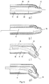
Figur 3 eine Schnittdarstellung eines ersten Ausführungsbeispiels des zum Patienten proximalen Endes eines erfindungsgemäßen Instruments, und zwar gerade mit herausgeschobener Nadelelektrode in Figur 3a und gerade mit hineingezogener Nadelelektrode in Figur 3b sowie gebogen mit herausgeschobener Nadelelektrode in Figur 3c und gebogen mit hineingezogener Nadelelektrode in Figur 3d. -
Figur 4 eine Schnittdarstellung eines zweiten Ausführungsbeispiels des zum Patienten proximalen Endes eines erfindungsgemäßen Instruments, und zwar gerade mit herausgeschobener Nadelelektrode in Figur 4a und gerade mit hineingezogener Nadelelektrode in Figur 4b sowie gebogen mit herausgeschobener Nadelelektrode in Figur 4c und gebogen mit hineingezogener Nadelelektrode in Figur 4d. -
Figur 5 eine Schnittdarstellung eines dritten Ausführungsbeispiels des zum Patienten proximalen Endes des erfindungsgemäßen Instruments, und zwar gerade mit herausgeschobener Nadelelektrode in Figur 5a und gerade mit hineingezogener Nadelelektrode in Figur 5b sowie gebogen mit herausgeschobener Nadelelektrode in Figur 5c und gebogen mit hineingezogerner Nadelelektrode in Figur 5d. -
Figur 6 eine Schnittdarstellung eines vierten Ausführungsbeispiels des zum Patienten proximalen Endes eines erfindungsgemäßen Instruments, und zwar gerade mit herausgeschobener Nadelelektrode in Figur 6a und mit hineingezogener Nadelelektrode in Figur 6b sowie gebogen mit herausgeschobener Nadelelektrode in Figur 6c und gebogen mit hineingezogener Nadelelektrode in Figur 6d. -
Figur 7 eine schematische Darstellung eines Ausführungsbeispiels eines erfindungsgemäßen Instruments. -
Figur 8 eine schematische Darstellung verschiedener Möglichkeiten des Antriebs für die Schneideelektrode, und zwar eines elektromagnetischen Antriebs in Figur 8a und eines pneumatischen Antriebs in Figur 8b - Figur 9 eine Ausgestaltung des erfindungsgemäßen Instruments. Hierbei ist der Schaft des Instruments plastisch biegbar gestaltet, so daß der Operateur das Instrument der jeweiligen anatomischen Situation anpassen kann.
-
Figur 10 in schematischer Darstellung ein Operationsrektoskop. -
Figur 11 eine Schnittdarstellung eines fünften Ausführungsbeispiels des zum Patienten proximalen Endes eines erfindungsgemäßen Instruments, und zwar gerade mit herausgeschobener Nadelelektrode in Figur 11a und gerade mit hineingezogener Nadelelektrode in Figur 11b sowie gebogen mit herausgeschobener Nadelelektrode in Figur 11c und gebogen mit hineingezogener Nadelelektrode in Figur 11d.
- Figure 1 is a schematic representation of tumorous changes in the rectum.
- Figure 2 is a schematic representation of an application of an instrument according to the invention.
- 3 shows a sectional illustration of a first exemplary embodiment of the end of an instrument according to the invention proximal to the patient, specifically with the needle electrode pushed out in FIG. 3a and straight with the needle electrode drawn in in FIG. 3b and bent with the needle electrode pushed out in FIG. 3c and bent with the needle electrode drawn in in FIG. 3d.
- 4 shows a sectional illustration of a second exemplary embodiment of the end of an instrument according to the invention proximal to the patient, specifically with the needle electrode pushed out in FIG. 4a and straight with the needle electrode pulled in in FIG. 4b and bent with the needle electrode pushed out in FIG. 4c and bent with the needle electrode pulled in in FIG. 4d.
- 5 shows a sectional illustration of a third exemplary embodiment of the end of the instrument according to the invention proximal to the patient, specifically with the needle electrode pushed out in FIG. 5a and straight with the needle electrode pulled in in FIG. 5b and bent with the needle electrode pushed out in FIG. 5c and bent with the needle electrode pulled in in FIG. 5d.
- FIG. 6 shows a sectional illustration of a fourth exemplary embodiment of the end of an instrument according to the invention which is proximal to the patient, specifically with the one pushed out 6a and with the needle electrode drawn in in FIG. 6b and bent with the needle electrode pushed out in FIG. 6c and bent with the needle electrode drawn in FIG. 6d.
- Figure 7 is a schematic representation of an embodiment of an instrument according to the invention.
- Figure 8 is a schematic representation of various possibilities of the drive for the cutting electrode, namely an electromagnetic drive in Figure 8a and a pneumatic drive in Figure 8b
- Figure 9 shows an embodiment of the instrument according to the invention. The shaft of the instrument is designed to be plastically bendable so that the surgeon can adapt the instrument to the particular anatomical situation.
- Figure 10 shows a schematic representation of a surgical rectoscope.
- FIG. 11 shows a sectional illustration of a fifth exemplary embodiment of the end of an instrument according to the invention proximal to the patient, specifically with the needle electrode pushed out in FIG. 11 a and straight with the needle electrode pulled in in FIG. 11 b and bent with the needle electrode pushed out in FIG. 11 c and bent with the needle electrode pulled in in FIG. 11 d.
Figur 1 zeigt Beispiele von tumorösen Veränderungen beispielsweise im Rektum 1, bei welchen ein erfindungsgemäßes Instrument beispielsweise angewendet werden kann, und zwar ulzerierende Karzinome 2, villöse Adenome 3, polypoide Karzinome 4, sessile adenomatöse Polypen 5, 6, 7 und/oder gestielte adenomatöse Polypen 8. Bei Anwendung von bisher bekannten Instrumenten können derartige tumoröse Veränderungen nicht so präzise und nicht ohne ständigem Wechseln von Schneide- und Koagulationsinstrumenten reseziert werden. FIG. 1 shows examples of tumorous changes, for example in rectum 1, in which an instrument according to the invention can be used, for example, ulcerating
Anhand von Figur 2 wird schematisch beispielsweise eine transanale Anwendung eines erfindungsgemäßen Instruments zur operativen Therapie eines Karzinoms im Rektum 1 dargestellt, wobei mit Rücksicht auf eine übersichtliche Darstellung nur das zum Patienten proximale Teil des Instruments 9 dargestellt ist. Das Instrument 9 ist transanal ins Rektum 1 eingeführt. In der Praxis erfolgt die Anwendung des Instruments durch ein geeignetes Operationsrektoskop, wie es in Figur 10 schematisch dargestellt ist. Das Instrument 9 ist bis zum abzutragenden Kartinom 2 eingeführt. Zum Resezieren des Karzinoms 2 ist die Nadelelektrode 11 aus dem Instrument 9 herausgeschoben. Wird während der Resektion ein Blutgefäß perforiert, so kann es mit dem als Koagulationselektrode anwendbaren Stirnfläche 14 des zum Patienten proximalen Endes der Hülse 12 bzw. des Instruments 9 koaguliert werden. Während einer Koagulation kann die Nadelelektrode 11 in das Instrument 9 zurückgezogen sein. Das zum Patienten proximale Ende der Hülse 12 bzw. des Instruments 9 ist gegen die Achse A des Schafts 13 in einem für den jeweiligen Anwendungszweck geeigneten Winkel W abgebogen. Der Schaft 13 und die Hülse 12 sind auf ihrer Außenfäche, exklusive der als Koagulationselektrode ausgebildeten konvexen Stirnfläche 14, mit einer elektrischen Isolation 10 ausgestattet.A transanal application of an instrument according to the invention for the operative therapy of a carcinoma in the rectum 1 is shown schematically with reference to FIG. 2 , only the part of the instrument 9 proximal to the patient being shown with a view to a clear representation. The instrument 9 is inserted transanal into the rectum 1 . In practice, the instrument is used by means of a suitable surgical rectoscope, as is shown schematically in FIG. 10. The instrument 9 is inserted up to the
Das erfindungsgemäße Instrument kann auf verschiedene Weisen betrieben bzw. an einen Hochfrequenzgenerator angeschlossen werden. So kann die Nadelelektrode 11 als monopolare Schneideelektrode betrieben werden, wobei als Gegenelektrode eine bei monopolaren Techniken übliche, bekannte Neutralelektrode in bekannter Weise auf der Haut des Patienten appliziert ist. Hierbei wird die Nadelelektrode 11 an die monopolare, aktive Ausgangsbuchse und die Neutralelektrode an die neutrale Ausgangsbuchse des Hochfrequenzgenerators angeschlossen. Als Gegenelektrode kann aber auch die Stirnfläche 14 der Hülse 12 verwendet werden, wie es in US-A-4,043,342 beschrieben ist. Hierbei wird die Nadelelektrode 11 an die monopolare, aktive Ausgangsbuchse und die Stirnfläche 14 der Hülse 12 an die neutrale Ausgangsbuchse des Hochfrequenzgenerators angeschlossen.The instrument according to the invention can be operated in various ways or connected to a high-frequency generator. Thus, the
Die Stirnfläche 14 der Hülse 12 kann als monopolare Koagulationselektrode betrieben werden, wobei als Gegenelektrode eine bei monopolaren Techniken übliche, bekannte Neutralelektrode in bekannter Weise auf der Haut des Patienten appliziert ist. Hierbei wird die als Koagulationselektrode dienende Stirnfläche 14 der Hülse 12 an die monopolare, aktive Ausgangsbuchse und die aufder Haut des Patienten applizierte Neutralelektrode an der neutralen Ausgangsbuchse des Hochfrequenzgenerators angeschlossen.The end face 14 of the
In Figur 3 ist das zum Patienten proximale Ende eines erfindungsgemäßen Instruments 9 im Schnitt dargestellt, und zwar gerade mit herausgeschobener Nadelelektrode 11 zum Schneiden in Figur 3a und gerade mit hineingezogener Nadelelektrode 11 zum Koagulieren, Saugen und/oder Spülen oder in Ruhestellung in Figur 3b sowie gebogen mit herausgeschobener Nadelelektrode zum Schneiden in Figur 3c und gebogen mit hineingezogener Nadelelektrode zum Koagulieren, Saugen und/oder Spülen oder in Ruhestellung in Figur 3d. In FIG. 3 the end of an instrument 9 according to the invention proximal to the patient is shown in section, specifically with the
Das zum Patienten proximale Ende dieses erfindungsgemäßen Instruments besteht aus einer metallischen, vorzugsweise runden Hülse 12, welche durch einen vorzugsweise runden, metallischen Schaft 13 verlängert ist. Hülse 12 und Schaft 13 können auch einstückig aus einem metallischen Rohr geformt sein, wie es in Figur 3b dargestellt ist. Der Schaft 13 kann eine derartige Länge haben, daß das Instrument auch für endoskopische Anwendungen geeignet ist. Hülse 12 und Schaft 13 sind auf ihrer äußeren Oberfläche exclusive der Stirnfläche 14 der Hülse 12, welche als Koagulationselektrode oder beim Schneiden mit der Nadelelektrode 11 als Neutralelektrode angewendet werden kann, mit einer elektrischen Isolierschicht 10 ausgestattet. In der Stirnfläche 14 der Hülse 12 ist ein Loch 16 vorhanden, durch welches die Nadelelektrode 11 hindurchschiebbar ist. Der Durchmesser dieses Lochs 16 ist so groß, daß die Isolation 15 der Nadelelektrode 11 einerseits leicht durch dieses Loch hindurchgeschoben werden kann und andererseits so eng, daß die Nadelelektrode 11 von der Hülse 12 ohne zu wackeln gut geführt wird.The proximal end of this instrument according to the invention to the patient consists of a metallic, preferably round
Der Innendurchmesser dH der Hülse 12 und/oder dS des Schafts 13 bzw. des Instruments 9 ist derart groß, daß zwischen dem Außendurchmesser dI der Isolation 15 der Nadelelektrode 11 und dem Innendurchmesser dH der Hülse 12 und dS des Schafts ein Kanal K zum Saugen und/oder Spülen vorhanden ist.The inner diameter d H of the
Die Außendurchmesser der Hülse 12 und des Schaftes 13 können prinzipiell gleich sein. Mit Rücksicht auf eine gute Sicht auf die Nadelelektrode 11 und eine nicht zu große effektive Kontaktfläche der als Koagulationselektrode oder beim Schneiden mittels der Nadelelektrode 11 als Neutralelektrode anwendbaren, vorzugsweise konvexen Stirnfläche 14 der Hülse 12 ist es jedoch zweckmäßig, den Außendurchmesser der Hülse 12 in der Nähe der Stirnfläche 14 möglichst klein, beispielsweise 3 bis 5 Millimeter zu wählen. Mit Rücksicht auf eine gute mechanische Stabilität des Instruments und einen möglichst großen Querschnitt des Saug- und/oder Spülkanals K ist es zweckmäßig, den Außendurchmesser des Schafts 13 nicht zu klein zu wählen, beispielsweise 5 bis 10 Millimeter. Der Außendurchmesser der Hülse 12 kann zweckmäßig in mindestens einer Stufe und/oder konisch, wie in Figur 3 dargestellt, vom Außendurchmesser des Schaftes 13 auf den Durchmesser der Stirnfläche 14 reduziert werden.The outer diameter of the
Die Nadelelektrode 11 ist mit einer elektrischen Isolation 15 gegen die metallische Hülse 12 und den Schaft 13 isoliert.The
Die Nadelelektrode 11 kann, wie in Figur 3b und 3d dargestellt, soweit in die Hülse 12 zurückgezogen werden, daß das Loch 16 in der Stirnfläche 14 zum Saugen und/oder Spülen frei ist.As shown in FIGS. 3b and 3d, the
Um zu gewährleisten, daß die zum Schneiden effektive Länge der aus der Stirnfläche 14 der Hülse 12 herausschiebbaren Nadelelektrode 11 möglichst genau und reproduzierbar einstellbar ist, muß die relativ dünne Nadel 11 entweder so innerhalb des relativ großlumigen Saug- und/oder Spülkanals geführt werden, daß sie sich innerhalb dieses Kanals nicht verbiegen kann, beispielsweise indem sie innerhalb des Kanals K gestützt wird, oder sie muß, wie beispielsweise bei den Ausführungsbeispielen in den Figuren 3a bis 3d dargestellt, innerhalb des Instruments auf den Durchmesser dN verstärkt werden.In order to ensure that the effective length for cutting the
Je nach Anwendungsgebiet kann es zweckmäßig sein, das Instrument gerade bzw. axial auszurichten, wie es beispielsweise in den Ausführungsbeispielen der Figuren 3a und 3b dargestellt ist, oder das zum Patienten proximale Ende der Hülse 12 und/oder des Schafts 13 bzw. des Instruments in einem für den jeweiligen Verwendungszweck geeigneten Winkel W abzubiegen, wie es beispielsweise in den Figuren 3c und 3d dargestellt ist.Depending on the area of application, it may be expedient to align the instrument straight or axially, as is shown, for example, in the exemplary embodiments in FIGS. 3a and 3b, or the end of the
Figur 4 zeigt eine Schnittdarstellung eines zweiten Ausführungsbeispiels des zum Patienten proximalen Endes eines erfindungsgemäßen Instruments, und zwar gerade mit herausgeschobener Nadelelektrode in Figur 4a und gerade mit hineingezogener Nadelelektrode in Figur 4b sowie gebogen mit herausgeschobener Nadelelektrode in Figur 4c und gebogen mit hineingezogener Nadelelektrodein Figur 4d. FIG. 4 shows a sectional illustration of a second exemplary embodiment of the end of an instrument according to the invention proximal to the patient, specifically with the needle electrode pushed out in FIG. 4a and straight with the needle electrode drawn in in FIG. 4b and bent with the needle electrode pushed out in FIG. 4c and bent with the needle electrode pulled in in FIG. 4d.
Dieses Ausführungsbeispiel unterscheidet sich zu dem Ausführungsbeispiel in den Figuren 3a bis 3d durch zusätzliche Löcher 17 zum Saugen und/oder Spülen in unmittelbarer Nähe zur Stirnfläche 14 der Hülse 12, welche vorzugsweise radial derart um das Loch 16 herum angeordnet sind, daß Saugen und/oder Spülen durch diese zusätzlichen Löcher 17 auch dann möglich ist, wenn die Nadelelektrode 11 aus dem Loch 16 herausgeschoben ist oder wenn die Nadelelektrode in die Hülse hineingezogen ist, das Loch 16 jedoch gegen Gewebe gedrückt wird, wie es beispielsweise während Koagulationen der Fall ist. Diese zusätzlichen Löcher 17 können auch zum Absaugen des während Scheide- und/oder Koagulationsvorgängen enstehenden Dampfs und/oder Rauchs angewendet werden.This embodiment differs from the embodiment in FIGS. 3a to 3d by
Hülse 12 und Schaft 13 können beispielsweise aus zwei Teilen zusammengefügt sein, wie es in Figur 4a dargestellt , oder sie können einstückig aus einem Rohrgeformt sein, wie es in Figur 4b dargestellt ist.
Figur 5 zeigt eine Schnittdarstellung eines dritten Ausführungsbeispiels des zum Patienten proximalen Endes eines erfindungsgemäßen Instruments, und zwar gerade mit herausgeschobener Nadelelektrode in Figur 5a und gerade mit hineingezogener Nadelelektrode in Figur 5b sowie gebogen mit herausgeschobener Nadelelektrode in Figur 5c und gebogen mit hineingezogerner Nadelelektrode in Figur 5d. FIG. 5 shows a sectional illustration of a third exemplary embodiment of the end of an instrument according to the invention which is proximal to the patient, specifically with the needle electrode in FIG. 5a pushed out and straight with the drawn-in one 5b and bent with the needle electrode pushed out in FIG. 5c and bent with the needle electrode drawn in in FIG. 5d.
Dieses Ausführungsbeispiel unterscheidet sich zu dem Ausführungsbeispiel der Figuren 3a bis 3d durch einen zusätzlichen Saug- und/oder Spülkanal 18, der beispielsweise konzentrisch zwischen den Außendurchmessern der Hülse 12 und des Schafts 13 und der Isolationsschicht 10 eingefügt ist. Die Distanz zwischen den Oberflächen von Hülse und Schaft einerseits und Isolationsschicht andererseits kann beispielsweise durch Noppen oder axiale Profile auf den Oberfächen von Hülse und Schaft oder der Innenfläche der Isolation 10 realisiert werden.This embodiment differs from the embodiment of FIGS. 3a to 3d by an additional suction and / or rinsing
Figur 6 zeigt eine Schnittdarstellung eines vierten Ausführungsbeispiels des zum Patienten proximalen Endes eines erfindungsgemäßen Instruments, und zwar gerade mit herausgeschobener Nadelelektrode in Figur 6a und gerade mit hineingezogener Nadelelektrode in Figur 6b sowie gebogen mit herausgeschobener Nadelelektrode in Figur 6c und gebogen mit hineingezogener Nadelelektrode in Figur 6d. FIG. 6 shows a sectional illustration of a fourth exemplary embodiment of the end of an instrument according to the invention which is proximal to the patient, specifically with the needle electrode pushed out in FIG. 6a and straight with the needle electrode pulled in in FIG. 6b and bent with the needle electrode pushed out in FIG. 6c and bent with the needle electrode pulled in in FIG. 6d .
Dieses Ausführungsbeispiel unterscheidet sich von dem in Figur 3 dargestellten Ausführungsbeispiel durch einen zusätzlichen Saug- und/oder Spülkanal, der beispielsweise durch ein Rohr 19 realisiert ist, welches parallel zur Hülse 12 und zum Schaft 13 geführt ist und beispielsweise auf der Oberfläche von Hülse und Schaft aufgelötet ist. Besteht dieses Rohr 19 aus Metall, so muß es wie die Hülse 12 und der Schaft 13 auf seiner Oberfläche mit einer elektrischen Isolierschicht 10 ausgestattet sein. Das Rohr 20 endet vorzugsweise kurz vor der Stirnfläche 14 der Hülse 12.This exemplary embodiment differs from the exemplary embodiment illustrated in FIG. 3 by an additional suction and / or rinsing channel, which is implemented, for example, by a
In Figur 7 ist schematisch ein Ausführungsbeispiel eines erfindungsgemäßen Instruments dargestellt. Am vom Patienten distalen Ende des Instruments ist ein Antrieb 22 zum Herausshieben bzw. Hineinziehen der Nadelelektrode 11 schematisch dargestellt. Dieser Antrieb 22 kann beispielsweise elektromagnetisch, wie in Figur 8a schematisch dargestellt, oder pneumatisch oder hydraulisch, wie in Figur 8b schematisch dargestellt, oder mechanisch, wie beispielsweise bei Kugelschreibern zum Heraus- und Hineinbewegen und Arretieren der Schreibmine bekannt, realisiert werden. Die Anschlüsse 23 und 24 sind entweder Elektroanschlüsse für einen elektromagnetischen Antrieb 22 oder Druckluftanschlüsse für einen pneumatischen Antrieb 22 oder Schlauchanschlüsse für einen hydraulichen Antrieb 22. Die elektrischen Anschlüsse 20 und 21 dienen zur HF-Stromversorgung der Nadelelektrode 11 und der als Neutralelektrode oder Koagulationselektrode anwendbaren Stirnfläche 14 der Hülse 12. 25 und 26 sind Anschlüsse für Saug- und/oder Spülleitungen um das Instrument mit Saug- und/oder Spüleinrichtungen zu verbinden.An exemplary embodiment of an instrument according to the invention is shown schematically in FIG . At the end of the instrument distal from the patient, a
In Figur 9 ist ein erfindungsgemäßes Instrument schematisch dargestellt, bei welchem der Schaft 13 vom Operateur plastisch so gebogen werden kann, daß es den individuellen bzw. anatomischen Verhältnissen angepaßt werden kann.An instrument according to the invention is shown schematically in FIG. 9 , in which the
Figur 10 zeigt in schematischer Darstellung ein Operationsrektoskop zur transanalen endoskopischen Resektion tumoröser Veränderungen im Rektum, durch welches hindurch das erfindungsgemäße Instrument beispielsweise angewendet werden kann. FIG. 10 shows a schematic representation of a surgical rectoscope for transanal endoscopic resection of tumorous changes in the rectum, through which the instrument according to the invention can be used, for example.
Figur 11 eine Schnittdarstellung eines fünften Ausführungsbeispiels des zum Patienten proximalen Endes eines erfindungsgemäßen Instruments, und zwar gerade mit herausgeschobener Nadelelektrode in Figur 11a und gerade mit hineingezogener Nadelelektrode in Figur 11b sowie gebogen mit herausgeschobener Nadelelektrode in Figur 11c und gebogen mit hineingezogener Nadelelektrode in Figur 11d. FIG. 11 shows a sectional illustration of a fifth exemplary embodiment of the end of an instrument according to the invention proximal to the patient, specifically with the needle electrode pushed out in FIG. 11 a and straight with the needle electrode pulled in in FIG. 11 b and bent with the needle electrode pushed out in FIG. 11 c and bent with the needle electrode pulled in in FIG. 11 d.
Bei dieser Ausführung eines erfindungsgemäßen Instruments sind zwei Kanäle K; 19 vorhanden, welche innerhalb und/oder außerhalb des Schafts 13 und/oder der Hülse 12, voneinander getrennt bis zur Hülse 12 und/oder bis kurz vor die Saug- und/oder Spüllöffnung 16 geführt werden, wo sie innerhalb des Instruments vereinigt in die gemeinsame Öffnung 16 einmünden, durch welche abwechselnd Saugen oder Spülen möglich ist. Bei einer derartigen Ausführung ergibt sich zusätzlich der Vorteil, daß eine einfache Reinigung des Saugkanals möglich ist indem die gemeinsamen Öffnung 16 beispielsweise durch Herausschieben der Nadelelektrode 11 geschlossen wird und die Spülflüssigkeit innerhalb des Instruments kurz vor der geschlossenen Öffnung 16 aus dem Spülkanal 19 in den Saugkanal K hineingesaugt wird um den Saugkanal K beispielsweise von Blut und anderen Gewebebestandteile zu reinigen. Das Instrument ist, beispielsweise für endoskopische Anwendungen, auf seiner Außenfläche, mit Ausnahme der als Neutralelektrode oder Koagulationselektrode dienenden, zum Patienten proximalen Stirnfläche 14 , elektrisch isoliert.In this embodiment of an instrument according to the invention, two channels K; 19 available, which are inside and / or outside of the
Claims (21)
Priority Applications (2)
| Application Number | Priority Date | Filing Date | Title |
|---|---|---|---|
| DE59108725T DE59108725D1 (en) | 1991-10-11 | 1991-10-11 | Instrument for high frequency surgery for cutting or coagulating |
| EP91117332A EP0536440B1 (en) | 1991-10-11 | 1991-10-11 | H.F. surgical instrument for cutting and coagulating |
Applications Claiming Priority (1)
| Application Number | Priority Date | Filing Date | Title |
|---|---|---|---|
| EP91117332A EP0536440B1 (en) | 1991-10-11 | 1991-10-11 | H.F. surgical instrument for cutting and coagulating |
Publications (2)
| Publication Number | Publication Date |
|---|---|
| EP0536440A1 true EP0536440A1 (en) | 1993-04-14 |
| EP0536440B1 EP0536440B1 (en) | 1997-05-28 |
Family
ID=8207256
Family Applications (1)
| Application Number | Title | Priority Date | Filing Date |
|---|---|---|---|
| EP91117332A Expired - Lifetime EP0536440B1 (en) | 1991-10-11 | 1991-10-11 | H.F. surgical instrument for cutting and coagulating |
Country Status (2)
| Country | Link |
|---|---|
| EP (1) | EP0536440B1 (en) |
| DE (1) | DE59108725D1 (en) |
Cited By (22)
| Publication number | Priority date | Publication date | Assignee | Title |
|---|---|---|---|---|
| DE4222769A1 (en) * | 1992-07-10 | 1994-01-13 | Erbe Elektromedizin | HF surgical instrument with at least one operation element allowing varying setting - has drive for operation element which is connected to electronic unit contg. hardware and software for producing control signals for drive |
| EP0658333A1 (en) * | 1993-12-17 | 1995-06-21 | United States Surgical Corporation | Monopolar electrosurgical instruments |
| ES2076124A1 (en) * | 1993-11-10 | 1995-10-16 | Garcia Manuel Garcia | Endosurgical tampon applicator |
| GB2269538B (en) * | 1992-08-12 | 1996-10-09 | Vidamed Inc | Medical probe |
| WO1997018766A1 (en) * | 1995-11-20 | 1997-05-29 | Storz Endoskop Gmbh | Bipolar high-frequency surgical instrument |
| WO1998022176A1 (en) * | 1996-11-18 | 1998-05-28 | Daig Corporation | Guiding introducer with openings containing ablation catheter |
| EP0923907A1 (en) * | 1997-12-19 | 1999-06-23 | Gyrus Medical Limited | An electrosurgical instrument |
| US6039734A (en) * | 1995-10-24 | 2000-03-21 | Gyrus Medical Limited | Electrosurgical hand-held battery-operated instrument |
| WO2000076434A1 (en) * | 1999-06-11 | 2000-12-21 | Alcon Laboratories, Inc. | Surgical handpiece tip |
| WO2004043531A3 (en) * | 2002-11-06 | 2004-08-12 | Senorx Inc | Vaccum device for treating tissus adjacent a body cavity |
| US7276060B2 (en) | 2004-02-26 | 2007-10-02 | Alcon, Inc. | Surgical handpiece tip |
| US7413539B2 (en) | 2005-11-18 | 2008-08-19 | Senorx, Inc. | Treatment of a body cavity |
| US7955246B2 (en) | 2002-11-06 | 2011-06-07 | Senorx, Inc. | Temporary catheter for biopsy site tissue fixation |
| US8079946B2 (en) | 2005-11-18 | 2011-12-20 | Senorx, Inc. | Asymmetrical irradiation of a body cavity |
| US8740763B2 (en) | 2008-01-24 | 2014-06-03 | Hologic Inc. | Multilumen brachytherapy balloon catheter |
| US8740873B2 (en) | 2007-03-15 | 2014-06-03 | Hologic, Inc. | Soft body catheter with low friction lumen |
| US8758214B2 (en) | 2007-03-12 | 2014-06-24 | Hologic, Inc. | Radiation catheter with multilayered balloon |
| US9623260B2 (en) | 2004-11-05 | 2017-04-18 | Theragenics Corporation | Expandable brachytherapy device |
| US10022557B2 (en) | 2010-09-30 | 2018-07-17 | Hologic, Inc. | Using a guided member to facilitate brachytherapy device swap |
| US10207126B2 (en) | 2009-05-11 | 2019-02-19 | Cytyc Corporation | Lumen visualization and identification system for multi-lumen balloon catheter |
| US10342992B2 (en) | 2011-01-06 | 2019-07-09 | Hologic, Inc. | Orienting a brachytherapy applicator |
| CN117137616A (en) * | 2023-10-25 | 2023-12-01 | 上海声拓医疗科技有限公司 | Surgical electrode and surgical system |
Families Citing this family (16)
| Publication number | Priority date | Publication date | Assignee | Title |
|---|---|---|---|---|
| CA2224975A1 (en) | 1995-06-23 | 1997-01-09 | Gyrus Medical Limited | An electrosurgical instrument |
| AU710619B2 (en) | 1995-06-23 | 1999-09-23 | Gyrus Medical Limited | An electrosurgical instrument |
| US6780180B1 (en) | 1995-06-23 | 2004-08-24 | Gyrus Medical Limited | Electrosurgical instrument |
| US6015406A (en) | 1996-01-09 | 2000-01-18 | Gyrus Medical Limited | Electrosurgical instrument |
| US6293942B1 (en) | 1995-06-23 | 2001-09-25 | Gyrus Medical Limited | Electrosurgical generator method |
| US6090106A (en) | 1996-01-09 | 2000-07-18 | Gyrus Medical Limited | Electrosurgical instrument |
| US6013076A (en) | 1996-01-09 | 2000-01-11 | Gyrus Medical Limited | Electrosurgical instrument |
| GB9612993D0 (en) | 1996-06-20 | 1996-08-21 | Gyrus Medical Ltd | Electrosurgical instrument |
| GB2314274A (en) | 1996-06-20 | 1997-12-24 | Gyrus Medical Ltd | Electrode construction for an electrosurgical instrument |
| US6565561B1 (en) | 1996-06-20 | 2003-05-20 | Cyrus Medical Limited | Electrosurgical instrument |
| GB9626512D0 (en) | 1996-12-20 | 1997-02-05 | Gyrus Medical Ltd | An improved electrosurgical generator and system |
| GB9807303D0 (en) | 1998-04-03 | 1998-06-03 | Gyrus Medical Ltd | An electrode assembly for an electrosurgical instrument |
| US8273006B2 (en) | 2005-11-18 | 2012-09-25 | Senorx, Inc. | Tissue irradiation |
| US9248311B2 (en) | 2009-02-11 | 2016-02-02 | Hologic, Inc. | System and method for modifying a flexibility of a brachythereapy catheter |
| US9579524B2 (en) | 2009-02-11 | 2017-02-28 | Hologic, Inc. | Flexible multi-lumen brachytherapy device |
| EP2604202B1 (en) | 2011-12-14 | 2015-04-01 | Erbe Elektromedizin GmbH | Instrument for water jet surgery |
Citations (4)
| Publication number | Priority date | Publication date | Assignee | Title |
|---|---|---|---|---|
| US2888928A (en) * | 1957-04-15 | 1959-06-02 | Seiger Harry Wright | Coagulating surgical instrument |
| US4307720A (en) * | 1979-07-26 | 1981-12-29 | Weber Jr Jaroy | Electrocautery apparatus and method and means for cleaning the same |
| US4326529A (en) * | 1978-05-26 | 1982-04-27 | The United States Of America As Represented By The United States Department Of Energy | Corneal-shaping electrode |
| US5007908A (en) * | 1989-09-29 | 1991-04-16 | Everest Medical Corporation | Electrosurgical instrument having needle cutting electrode and spot-coag electrode |
-
1991
- 1991-10-11 DE DE59108725T patent/DE59108725D1/en not_active Expired - Lifetime
- 1991-10-11 EP EP91117332A patent/EP0536440B1/en not_active Expired - Lifetime
Patent Citations (4)
| Publication number | Priority date | Publication date | Assignee | Title |
|---|---|---|---|---|
| US2888928A (en) * | 1957-04-15 | 1959-06-02 | Seiger Harry Wright | Coagulating surgical instrument |
| US4326529A (en) * | 1978-05-26 | 1982-04-27 | The United States Of America As Represented By The United States Department Of Energy | Corneal-shaping electrode |
| US4307720A (en) * | 1979-07-26 | 1981-12-29 | Weber Jr Jaroy | Electrocautery apparatus and method and means for cleaning the same |
| US5007908A (en) * | 1989-09-29 | 1991-04-16 | Everest Medical Corporation | Electrosurgical instrument having needle cutting electrode and spot-coag electrode |
Cited By (37)
| Publication number | Priority date | Publication date | Assignee | Title |
|---|---|---|---|---|
| DE4222769A1 (en) * | 1992-07-10 | 1994-01-13 | Erbe Elektromedizin | HF surgical instrument with at least one operation element allowing varying setting - has drive for operation element which is connected to electronic unit contg. hardware and software for producing control signals for drive |
| GB2269538B (en) * | 1992-08-12 | 1996-10-09 | Vidamed Inc | Medical probe |
| ES2076124A1 (en) * | 1993-11-10 | 1995-10-16 | Garcia Manuel Garcia | Endosurgical tampon applicator |
| EP0658333A1 (en) * | 1993-12-17 | 1995-06-21 | United States Surgical Corporation | Monopolar electrosurgical instruments |
| US5766167A (en) * | 1993-12-17 | 1998-06-16 | United States Surgical Corporation | Monopolar electrosurgical Instruments |
| US6039734A (en) * | 1995-10-24 | 2000-03-21 | Gyrus Medical Limited | Electrosurgical hand-held battery-operated instrument |
| WO1997018766A1 (en) * | 1995-11-20 | 1997-05-29 | Storz Endoskop Gmbh | Bipolar high-frequency surgical instrument |
| WO1998022176A1 (en) * | 1996-11-18 | 1998-05-28 | Daig Corporation | Guiding introducer with openings containing ablation catheter |
| EP0923907A1 (en) * | 1997-12-19 | 1999-06-23 | Gyrus Medical Limited | An electrosurgical instrument |
| WO2000076434A1 (en) * | 1999-06-11 | 2000-12-21 | Alcon Laboratories, Inc. | Surgical handpiece tip |
| US7955246B2 (en) | 2002-11-06 | 2011-06-07 | Senorx, Inc. | Temporary catheter for biopsy site tissue fixation |
| US8398535B2 (en) | 2002-11-06 | 2013-03-19 | Senorx, Inc. | Catheter assembly for delivering a radiation source into a body cavity |
| US7214178B2 (en) | 2002-11-06 | 2007-05-08 | Senorx, Inc. | Vacuum device and method for treating tissue adjacent a body cavity |
| US6955641B2 (en) | 2002-11-06 | 2005-10-18 | Senorx, Inc. | Vacuum device and method for treating tissue adjacent a body cavity |
| EP2305340A1 (en) * | 2002-11-06 | 2011-04-06 | Senorx, Inc. | Vacuum device for treating tissus adjacent a body cavity |
| US7935044B2 (en) | 2002-11-06 | 2011-05-03 | Senorx, Inc. | Vacuum device and method for treating tissue adjacent a body cavity |
| US7942802B2 (en) | 2002-11-06 | 2011-05-17 | Senorx, Inc. | Vacuum device and method for treating tissue adjacent a body cavity |
| WO2004043531A3 (en) * | 2002-11-06 | 2004-08-12 | Senorx Inc | Vaccum device for treating tissus adjacent a body cavity |
| US8517906B2 (en) | 2002-11-06 | 2013-08-27 | Hologic, Inc. | Brachytherapy device |
| US8292794B2 (en) | 2002-11-06 | 2012-10-23 | Senorx, Inc. | Method for maintaining access to a biopsy site |
| US7276060B2 (en) | 2004-02-26 | 2007-10-02 | Alcon, Inc. | Surgical handpiece tip |
| US9623260B2 (en) | 2004-11-05 | 2017-04-18 | Theragenics Corporation | Expandable brachytherapy device |
| US9808650B2 (en) | 2004-11-05 | 2017-11-07 | Theragenics Corporation | Expandable brachytherapy device |
| US8636637B2 (en) | 2005-11-18 | 2014-01-28 | Hologic, Inc | Methods for asymmetrical irradiation of a body cavity |
| US10413750B2 (en) | 2005-11-18 | 2019-09-17 | Hologic, Inc. | Brachytherapy device for facilitating asymmetrical irradiation of a body cavity |
| US8079946B2 (en) | 2005-11-18 | 2011-12-20 | Senorx, Inc. | Asymmetrical irradiation of a body cavity |
| US9180312B2 (en) | 2005-11-18 | 2015-11-10 | Hologic, Inc. | Brachytherapy device for asymmetrical irradiation of a body cavity |
| US9415239B2 (en) | 2005-11-18 | 2016-08-16 | Hologic, Inc. | Brachytherapy device for facilitating asymmetrical irradiation of a body cavity |
| US7413539B2 (en) | 2005-11-18 | 2008-08-19 | Senorx, Inc. | Treatment of a body cavity |
| US8758214B2 (en) | 2007-03-12 | 2014-06-24 | Hologic, Inc. | Radiation catheter with multilayered balloon |
| US8740873B2 (en) | 2007-03-15 | 2014-06-03 | Hologic, Inc. | Soft body catheter with low friction lumen |
| US8740763B2 (en) | 2008-01-24 | 2014-06-03 | Hologic Inc. | Multilumen brachytherapy balloon catheter |
| US10207126B2 (en) | 2009-05-11 | 2019-02-19 | Cytyc Corporation | Lumen visualization and identification system for multi-lumen balloon catheter |
| US10022557B2 (en) | 2010-09-30 | 2018-07-17 | Hologic, Inc. | Using a guided member to facilitate brachytherapy device swap |
| US10342992B2 (en) | 2011-01-06 | 2019-07-09 | Hologic, Inc. | Orienting a brachytherapy applicator |
| CN117137616A (en) * | 2023-10-25 | 2023-12-01 | 上海声拓医疗科技有限公司 | Surgical electrode and surgical system |
| CN117137616B (en) * | 2023-10-25 | 2024-01-16 | 上海声拓医疗科技有限公司 | Surgical electrode and surgical system |
Also Published As
| Publication number | Publication date |
|---|---|
| EP0536440B1 (en) | 1997-05-28 |
| DE59108725D1 (en) | 1997-07-03 |
Similar Documents
| Publication | Publication Date | Title |
|---|---|---|
| EP0536440B1 (en) | H.F. surgical instrument for cutting and coagulating | |
| DE602005001776T2 (en) | Bipolar electrosurgical sling | |
| EP0954246B1 (en) | Coagulation device for coagulating biological tissues | |
| DE60024877T2 (en) | ELEKTROKAUTERISATIONSKATHETER | |
| DE19847852B4 (en) | Treatment instrument for an endoscope | |
| EP0815796B1 (en) | Trocar for laparoscopic operations | |
| DE69829007T2 (en) | MULTIFUNCTIONAL TELESCOPIC ELECTRO-SURGERY DEVICE | |
| DE60117398T2 (en) | SURGICAL MICRO RESEARCH INSTRUMENT WITH ELECTROCAUTERISATION FEATURE | |
| DE102008039751B4 (en) | Electrosurgical stylus with integrated smoke evacuation and method therefor | |
| EP0530400B1 (en) | H.F.-Surgical instrument for cutting and coagulating | |
| EP2029039B1 (en) | Device for cutting and coagulation of tissue | |
| DE69735270T2 (en) | FINGERPIECE INSTRUMENT FOR MINIMAL INVASIVE SURGERY | |
| DE69631261T2 (en) | Liquid-assisted electrosurgical device with rolling ball | |
| DE60028863T2 (en) | Electrosurgical handpiece for the treatment of tissue | |
| DE19706751A1 (en) | Electrosurgical device for removing tissue in body areas | |
| EP1256325B1 (en) | Urological resectoscope with insulating mantel | |
| EP0886495B1 (en) | Cutting device for electrotomy | |
| EP2558017B1 (en) | Electrode arrangement | |
| EP1567079B1 (en) | Bipolar medical instrument and electrosurgical system comprising one such instrument | |
| EP1752107B1 (en) | Medical instrument | |
| DE10354830B4 (en) | High frequency cutter | |
| DE112018001152T5 (en) | MONOPOLAR ELECTRO-SURGICAL PEN WITH ARGONIZED RADIATION | |
| DE10212841B4 (en) | Medical instrument for the treatment of tissue by means of high frequency current and medical system with such a medical instrument | |
| EP3471642B1 (en) | Surgical instrument for electrotomy and tool for same | |
| EP3372183B1 (en) | Instrument for ablation |
Legal Events
| Date | Code | Title | Description |
|---|---|---|---|
| PUAI | Public reference made under article 153(3) epc to a published international application that has entered the european phase |
Free format text: ORIGINAL CODE: 0009012 |
|
| AK | Designated contracting states |
Kind code of ref document: A1 Designated state(s): DE FR GB IT NL |
|
| 17P | Request for examination filed |
Effective date: 19931012 |
|
| 17Q | First examination report despatched |
Effective date: 19950427 |
|
| GRAG | Despatch of communication of intention to grant |
Free format text: ORIGINAL CODE: EPIDOS AGRA |
|
| GRAH | Despatch of communication of intention to grant a patent |
Free format text: ORIGINAL CODE: EPIDOS IGRA |
|
| GRAH | Despatch of communication of intention to grant a patent |
Free format text: ORIGINAL CODE: EPIDOS IGRA |
|
| GRAA | (expected) grant |
Free format text: ORIGINAL CODE: 0009210 |
|
| ITF | It: translation for a ep patent filed |
Owner name: BARZANO' E ZANARDO MILANO S.P.A. |
|
| AK | Designated contracting states |
Kind code of ref document: B1 Designated state(s): DE FR GB IT NL |
|
| GBT | Gb: translation of ep patent filed (gb section 77(6)(a)/1977) |
Effective date: 19970528 |
|
| REF | Corresponds to: |
Ref document number: 59108725 Country of ref document: DE Date of ref document: 19970703 |
|
| ET | Fr: translation filed | ||
| PLBE | No opposition filed within time limit |
Free format text: ORIGINAL CODE: 0009261 |
|
| STAA | Information on the status of an ep patent application or granted ep patent |
Free format text: STATUS: NO OPPOSITION FILED WITHIN TIME LIMIT |
|
| 26N | No opposition filed | ||
| REG | Reference to a national code |
Ref country code: GB Ref legal event code: IF02 |
|
| PGFP | Annual fee paid to national office [announced via postgrant information from national office to epo] |
Ref country code: NL Payment date: 20101029 Year of fee payment: 20 Ref country code: FR Payment date: 20101104 Year of fee payment: 20 |
|
| PGFP | Annual fee paid to national office [announced via postgrant information from national office to epo] |
Ref country code: GB Payment date: 20101029 Year of fee payment: 20 Ref country code: IT Payment date: 20101030 Year of fee payment: 20 |
|
| PGFP | Annual fee paid to national office [announced via postgrant information from national office to epo] |
Ref country code: DE Payment date: 20101230 Year of fee payment: 20 |
|
| REG | Reference to a national code |
Ref country code: DE Ref legal event code: R071 Ref document number: 59108725 Country of ref document: DE |
|
| REG | Reference to a national code |
Ref country code: DE Ref legal event code: R071 Ref document number: 59108725 Country of ref document: DE |
|
| REG | Reference to a national code |
Ref country code: NL Ref legal event code: V4 Effective date: 20111011 |
|
| REG | Reference to a national code |
Ref country code: GB Ref legal event code: PE20 Expiry date: 20111010 |
|
| PG25 | Lapsed in a contracting state [announced via postgrant information from national office to epo] |
Ref country code: NL Free format text: LAPSE BECAUSE OF EXPIRATION OF PROTECTION Effective date: 20111011 |
|
| PG25 | Lapsed in a contracting state [announced via postgrant information from national office to epo] |
Ref country code: GB Free format text: LAPSE BECAUSE OF EXPIRATION OF PROTECTION Effective date: 20111010 |
|
| PG25 | Lapsed in a contracting state [announced via postgrant information from national office to epo] |
Ref country code: DE Free format text: LAPSE BECAUSE OF EXPIRATION OF PROTECTION Effective date: 20111012 |