EP0535749B1 - Local communication bus system - Google Patents
Local communication bus system Download PDFInfo
- Publication number
- EP0535749B1 EP0535749B1 EP92202992A EP92202992A EP0535749B1 EP 0535749 B1 EP0535749 B1 EP 0535749B1 EP 92202992 A EP92202992 A EP 92202992A EP 92202992 A EP92202992 A EP 92202992A EP 0535749 B1 EP0535749 B1 EP 0535749B1
- Authority
- EP
- European Patent Office
- Prior art keywords
- user
- menu
- subdevice
- control
- avc
- Prior art date
- Legal status (The legal status is an assumption and is not a legal conclusion. Google has not performed a legal analysis and makes no representation as to the accuracy of the status listed.)
- Expired - Lifetime
Links
Images
Classifications
-
- G—PHYSICS
- G06—COMPUTING; CALCULATING OR COUNTING
- G06F—ELECTRIC DIGITAL DATA PROCESSING
- G06F13/00—Interconnection of, or transfer of information or other signals between, memories, input/output devices or central processing units
-
- H—ELECTRICITY
- H04—ELECTRIC COMMUNICATION TECHNIQUE
- H04N—PICTORIAL COMMUNICATION, e.g. TELEVISION
- H04N7/00—Television systems
- H04N7/10—Adaptations for transmission by electrical cable
- H04N7/106—Adaptations for transmission by electrical cable for domestic distribution
-
- H—ELECTRICITY
- H02—GENERATION; CONVERSION OR DISTRIBUTION OF ELECTRIC POWER
- H02J—CIRCUIT ARRANGEMENTS OR SYSTEMS FOR SUPPLYING OR DISTRIBUTING ELECTRIC POWER; SYSTEMS FOR STORING ELECTRIC ENERGY
- H02J13/00—Circuit arrangements for providing remote indication of network conditions, e.g. an instantaneous record of the open or closed condition of each circuitbreaker in the network; Circuit arrangements for providing remote control of switching means in a power distribution network, e.g. switching in and out of current consumers by using a pulse code signal carried by the network
- H02J13/00006—Circuit arrangements for providing remote indication of network conditions, e.g. an instantaneous record of the open or closed condition of each circuitbreaker in the network; Circuit arrangements for providing remote control of switching means in a power distribution network, e.g. switching in and out of current consumers by using a pulse code signal carried by the network characterised by information or instructions transport means between the monitoring, controlling or managing units and monitored, controlled or operated power network element or electrical equipment
- H02J13/00016—Circuit arrangements for providing remote indication of network conditions, e.g. an instantaneous record of the open or closed condition of each circuitbreaker in the network; Circuit arrangements for providing remote control of switching means in a power distribution network, e.g. switching in and out of current consumers by using a pulse code signal carried by the network characterised by information or instructions transport means between the monitoring, controlling or managing units and monitored, controlled or operated power network element or electrical equipment using a wired telecommunication network or a data transmission bus
- H02J13/00017—Circuit arrangements for providing remote indication of network conditions, e.g. an instantaneous record of the open or closed condition of each circuitbreaker in the network; Circuit arrangements for providing remote control of switching means in a power distribution network, e.g. switching in and out of current consumers by using a pulse code signal carried by the network characterised by information or instructions transport means between the monitoring, controlling or managing units and monitored, controlled or operated power network element or electrical equipment using a wired telecommunication network or a data transmission bus using optical fiber
-
- H—ELECTRICITY
- H04—ELECTRIC COMMUNICATION TECHNIQUE
- H04B—TRANSMISSION
- H04B1/00—Details of transmission systems, not covered by a single one of groups H04B3/00 - H04B13/00; Details of transmission systems not characterised by the medium used for transmission
- H04B1/06—Receivers
- H04B1/16—Circuits
- H04B1/20—Circuits for coupling gramophone pick-up, recorder output, or microphone to receiver
- H04B1/205—Circuits for coupling gramophone pick-up, recorder output, or microphone to receiver with control bus for exchanging commands between units
-
- H—ELECTRICITY
- H04—ELECTRIC COMMUNICATION TECHNIQUE
- H04L—TRANSMISSION OF DIGITAL INFORMATION, e.g. TELEGRAPHIC COMMUNICATION
- H04L12/00—Data switching networks
- H04L12/28—Data switching networks characterised by path configuration, e.g. LAN [Local Area Networks] or WAN [Wide Area Networks]
- H04L12/40—Bus networks
-
- H—ELECTRICITY
- H04—ELECTRIC COMMUNICATION TECHNIQUE
- H04N—PICTORIAL COMMUNICATION, e.g. TELEVISION
- H04N5/00—Details of television systems
- H04N5/76—Television signal recording
- H04N5/765—Interface circuits between an apparatus for recording and another apparatus
-
- Y—GENERAL TAGGING OF NEW TECHNOLOGICAL DEVELOPMENTS; GENERAL TAGGING OF CROSS-SECTIONAL TECHNOLOGIES SPANNING OVER SEVERAL SECTIONS OF THE IPC; TECHNICAL SUBJECTS COVERED BY FORMER USPC CROSS-REFERENCE ART COLLECTIONS [XRACs] AND DIGESTS
- Y02—TECHNOLOGIES OR APPLICATIONS FOR MITIGATION OR ADAPTATION AGAINST CLIMATE CHANGE
- Y02B—CLIMATE CHANGE MITIGATION TECHNOLOGIES RELATED TO BUILDINGS, e.g. HOUSING, HOUSE APPLIANCES OR RELATED END-USER APPLICATIONS
- Y02B90/00—Enabling technologies or technologies with a potential or indirect contribution to GHG emissions mitigation
- Y02B90/20—Smart grids as enabling technology in buildings sector
-
- Y—GENERAL TAGGING OF NEW TECHNOLOGICAL DEVELOPMENTS; GENERAL TAGGING OF CROSS-SECTIONAL TECHNOLOGIES SPANNING OVER SEVERAL SECTIONS OF THE IPC; TECHNICAL SUBJECTS COVERED BY FORMER USPC CROSS-REFERENCE ART COLLECTIONS [XRACs] AND DIGESTS
- Y04—INFORMATION OR COMMUNICATION TECHNOLOGIES HAVING AN IMPACT ON OTHER TECHNOLOGY AREAS
- Y04S—SYSTEMS INTEGRATING TECHNOLOGIES RELATED TO POWER NETWORK OPERATION, COMMUNICATION OR INFORMATION TECHNOLOGIES FOR IMPROVING THE ELECTRICAL POWER GENERATION, TRANSMISSION, DISTRIBUTION, MANAGEMENT OR USAGE, i.e. SMART GRIDS
- Y04S40/00—Systems for electrical power generation, transmission, distribution or end-user application management characterised by the use of communication or information technologies, or communication or information technology specific aspects supporting them
- Y04S40/12—Systems for electrical power generation, transmission, distribution or end-user application management characterised by the use of communication or information technologies, or communication or information technology specific aspects supporting them characterised by data transport means between the monitoring, controlling or managing units and monitored, controlled or operated electrical equipment
Definitions
- the invention relates to a local communication bus system comprising first and second apparatuses connected for the exchange of messages to a serial data channel.
- the invention relates in particular, but not exclusively, to a system of domestic audio and video apparatuses interconnected by a serial data channel bus for the exchange of control messages.
- a local communication bus system of the above type configured to link a number of home electronic apparatuses for the distribution of control data and collation of apparatus current-status data, is described in European patent application EP-A-0 369 382.
- a television interfaced to the bus system provides a user interface, with items such as device status messages being displayed overlaying any video program currently being displayed via the television.
- the television controls, and more particularly a remote control unit provide the user's input by enabling the user to select from different options displayed.
- a known serial data channel of the type referred to in the opening paragraph is provided by the Domestic Digital Bus (D2B), standardised by the International Electrotechnical Commission (IEC), Geneva.
- D2B is a trademark of Philips Electronics NV.
- apparatuses including D2B interfaces are Philips' model 2070 television receiver and model VR6590 video cassette recorder (VCR) previously available in Europe.
- VCR video cassette recorder
- Such a data channel has many applications, and it is desired that a standardised set of application protocols' be developed, in addition to the basic communication protocols defined by the IEC, and that these protocols should be adhered to by many manufacturers of consumer apparatus. In particular, the use of such protocols can bring enhanced functionality and ease of use to the great variety of consumer electronic apparatuses available today and in the future, with true inter-brand compatibility.
- the above apparatuses including D2B interfaces provide for integrated on-screen display facilities, so that a user controlling the VCR can receive information about the progress of VCR operations via the television screen.
- Such a feature is described in more detail in our co-pending European patent application EP-0 505 006-A2, not published at the priority date of the present application.
- EP-0 505 006-A2 not published at the priority date of the present application.
- There is a desire to integrate further the operation of the apparatuses of the system for example to allow the user to have dialogue with an apparatus which itself has inadequate user input/output facilities.
- One example would be to provide menu driven control of an apparatus which itself has no means for displaying a menu, and/or no means for relating a displayed menu to input received from the user.
- the invention provides a local communication system comprising first and second apparatuses connected for the exchange of messages to a serial data channel, the system including control means within the first apparatus and user interface means within the second apparatus, said control means including: means for initiating a user dialogue session with the second apparatus; means for during said user dialogue session sending to the second apparatus at least one user information item for presentation to a user of the system; means for during said user dialogue session receiving from the second apparatus information which conveys user control signals; and means for controlling at least part of the system in accordance with user's wishes inferred from the said information, said user interface means including:
- the system allows integration of user dialogue functions over the system as a whole. If the manner of establishing the user dialogue session is standardised, this holds true even though the different apparatuses may come from different manufacturers. At the same time, the designers of new apparatuses for use in such a system will be constrained as little as possible by the existing features when developing new user dialogue features.
- the user information items include items presented by the user interface means in a menu for control of the first apparatus, and the above-mentioned means for identifying an association is arranged to identify an association between a user control signal and a specific one of said menu items.
- the division of the menu control function in this manner between apparatuses allows the first apparatus to define the information content of the menu (by means of text strings or icons, for example) without regard for the style of menu presentation by the second apparatus (which might even speak the menu information to the user down a telephone line).
- the manner and style of selection of menu items is also unknown to the first apparatus: items might be selected by number, colour or by a movable pointer on screen. This allows maximum design independence for the manufacturers of both apparatuses.
- a VCR may initiate a user dialogue session, using the on-screen display facilities and remote control handset of a TV set (second apparatus). If the user selects to record from a channel which is scrambled (encrypted) the VCR can automatically decide to transfer the user dialogue session to a conditional access sub-system (third apparatus), in order that the user can obtain the necessary entitlement to descramble the signals for recording by the VCR.
- the invention is not limited to a system of three apparatuses, or to any fixed configuration.
- the third apparatus may in turn transfer the user dialogue session to a fourth apparatus, and so on.
- an integrated sequence of user dialogue operations can be provided spanning the functions of several apparatuses, to implement the user's wishes in a user-friendly manner, with each control means deciding freely which apparatus is in the best position to implement the user's wishes at each stage of operation.
- the above-mentioned means for initiating a user dialogue session of the first apparatus may include means for storing data identifying the second apparatus for the duration of the user dialogue session, while the user interface means within the second apparatus includes means for storing data identifying the apparatus with which it currently has a user dialogue session.
- the device-subdevice address of the control means may be stored.
- the second apparatus in such an embodiment may act as intermediary between the first and third apparatuses in the transfer of the user dialogue session. This ensures that each apparatus need communicate only with one other in the course of its user dialogue session, no matter how many apparatuses are involved in the process as a whole. Thus small and finite data storage facilities are sufficient for each apparatus, which is important for the designer of mass-market consumer apparatuses.
- the further control means within the third apparatus may for example include means for storing data identifying the first and second apparatuses during the continuation of the user dialogue session by the third apparatus. There is thus no need for the second apparatus to remember the identity of more than one other apparatus, at least with regard to the user dialogue function.
- each of the third and subsequent apparatuses is responsible for remembering the apparatus which transferred the user dialogue session to it, and therefore can further include means for initiating the return of the user dialogue session to that apparatus.
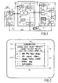
- Figure 1 shows a domestic video entertainment system comprising a satellite broadcast tuner 10, a video cassette recorder (VCR) 12 and a television receiver 14, all connected to a serial data bus 16.
- Video and audio signals are passed within and between the devices 10,12,14 using, for example, SCART (Euroconnector) plugs, sockets and multi-wire cables.
- SCART Euroconnector
- serial data bus is in this embodiment a Domestic Digital Bus (D2B) as standardised by the International Electrotechnical Commission (IEC), Geneva.
- D2B provides for distributed control of the bus, and allows commands and other messages to be uniquely addressed for specific "devices”, such as the apparatuses 10,12 and 14, and also for specific "subdevices" within each device.
- each device 10,12,14 there are shown blocks representing D2B subdevices.
- the division of a device into subdevices is necessary only in a logical sense, that is to say, from the point of view of its behaviour relative to the serial bus 16.
- each device includes one audio/video controller (AVC) type of subdevice plus others which are logically separate and logically connected to the bus as indicated by the dotted data paths in Figure 1.
- the AVC subdevices provide the (distributed) controlling logic of the system as a whole, interpreting user commands and controlling the operation of the system accordingly.
- control logic of the AVC and some or all of the other subdevices will often be integrated using a single programmed microcontroller.
- Other subdevices not shown in Figure 1 will generally be included in such a system, including timers, audio amplifiers, and so forth, and the subdevices described herein are presented as a representative sample only.
- a tuner subdevice 26 performs the signal processing functions necessary to provide baseband video signals to the connected apparatuses.
- the AVC subdevice 20 receives user instructions from a user input/output (User I/O) subdevice 27 (UIO) (the front panel and/or remote control of the satellite tuner) and D2B messages from the bus 16, and operates to select channels, keep track of preset channel selections and so forth.
- User I/O subdevice 27 the front panel and/or remote control of the satellite tuner
- the VCR device 12 includes its AVC subdevice 22, and also a User I/O subdevice 29 (UIO), a terrestrial broadcast tuner subdevice 28 (TUN), a switchbox subdevice 30 (SB) and a videotape record/replay deck 32 (DCK).
- UIO User I/O subdevice 29
- TUN terrestrial broadcast tuner subdevice 28
- SB switchbox subdevice 30
- DCK videotape record/replay deck 32
- the television receiver device 14 includes its AVC subdevice 24 and also a user input/output subdevice 41 (UIO), a terrestrial tuner subdevice 42 (TUN), a switchbox subdevice 44 (SB) and a video monitor subdevice 46 (VID).
- the User I/O subdevice 41 of the television receiver includes an on-screen display (OSD) function, as described hereinafter, and a remote control 41a for the receipt of user control signals.
- OSD on-screen display
- the tuner subdevices 26,28 and 42 can be regarded as sources of video signals with in the system.
- the video monitor subdevice 46 can act as a destination for video signals, and functions to display images to the user.
- the record/replay deck subdevice 32 can act as a source and/or a destination of video signals, depending whether it is playing and/or recording at a given time.
- any of the AVC subdevices 20,22,24 can take control of the bus and address commands to those subdevices. This is done for example by an AVC subdevice which has been informed of a user command by a User I/O subdevice and requires control of subdevices at various points in the system to implement the user's wishes.
- D2B message formats for controlling the basic functions of certain common subdevices are defined already in the IEC standard referred to above, while scope is left for defining not only new commands, but also request and reply messages that enable one D2B device or subdevice to interrogate another as to its properties and status.
- Each switchbox subdevice 30 and 44 can be controlled via the bus (or by its associated AVC subdevice) to connect its output data paths(s) a specified one of its input data paths.
- suitably addressed and coded D2B messages can be sent via the bus 16 to ensure that the satellite tuner 10, VCR 12 and the television 14 are active, to cause the satellite tuner 10 to select the appropriate channel, to cause the VCR switchbox subdevice 30 and the television switchbox subdevice 44 to connect the appropriate signal path from source to destination.
- the whole process can be controlled by the AVC subdevice of the device which receives the user input.
- the information necessary for building the signal path from source to destination can be obtained by a suitable series of D2B request messages to the relevant devices and subdevices.
- a suitable system for providing such control is described in GB-2 223 114-A1. In that system no AVC subdevice requires knowledge of the complete system, only its nearest neighbours.
- any AVC subdevice may wish to display user messages using the on-screen display (OSD) facility of the User I/O subdevice 41.
- OSD on-screen display
- the AVC 24 may wish to confirm visually for the user which channel is being watched. If the signal comes from the satellite tuner 10, a conventional on-screen display would be able to confirm no more than the fact that the signal is coming from an external connector of the television 14.
- the device information process provides only a one-way flow of information, however.
- a user-friendly operation could be enhanced by the ability for the VCR 12 and satellite tuner 10 to display menus for the user using the OSD function of the User I/O subdevice 41 of the television 14, and to receive the user's menu selections back from the User I/O subdevice to control further operation.
- menu control functions are now defined in the AVC subdevices 20 and 22, and in the User I/O subdevice 41 of the television.
- the menu control functions are standardised for reliable operation, but allowing as much freedom as possible for the manufacturers of the different apparatuses to provide their own style of implementation.
- the television manufacturer might develop a particular visual style of menu, with use of special text fonts and colour-coding of menu entries, for example, while the VCR manufacturer might develop a particularly efficient and intuitively operable menu tree structure. Both of these elements can be combined by appropriate partitioning of responsibilities between subdevices in the menu control function, as described below.
- Figure 2 shows a standardised menu window layout, of the type that can be generated in the embodiment described.
- the menu window 200 is divided into a header filed 210, an information field 212 and a selection field 214.
- the header field has room for a single line of text 216, of a length W characters, which text is defined by a string of W character codes in accordance with a standard character set.
- the information field contains room for a number H1 of lines of W text characters, and can be used by the AVC to give instructions to the user.
- the selection field 214 has room for a number H2 of items for user selection.
- the AVC provides a text string of W-4 characters to identify the item to the user.
- the leftmost four characters are available for the User I/O subdevice to show selection key information 218 for each item.
- buttons marked 'a', 'b', 'c', 'd' and 'e' on the remote control handset 41a of the television 14, and the User I/O subdevice 41 recognises these buttons as selectors of the five displayed menu items.
- Alternative embodiments might use other symbols, or colour coding as the selection key information.
- the present embodiment distinguishes between the functions of an AVC subdevice and a User I/O subdevice, and defines the means of cooperation between the two subdevices.
- the AVC subdevice has three states: Inactive, Active and Exchanged.
- Inactive state the AVC is currently not engaged in a menu control session.
- Active state the AVC is currently engaged in a menu control session on a certain User I/O subdevice or it is trying to establish a menu control session with a User I/O subdevice.
- Exchanged state the AVC is engaged in a menu control session, but one of the generated menus has given the user the ability to transfer menu control to another device, and the right of menu control has transferred to the AVC subdevice of that device.
- each AVC is only able to start a menu control session if it is in the Inactive state. In the other states the AVC will not start a menu control session when requested by a local event or a [menu][on] command, described below.
- an AVC maintains the following data items:
- the User I/O subdevice has three states, Off, On and Transferring.
- the Off state no menu is displayed.
- the On state one menu is currently displayed or is about to be displayed.
- the Transferring state the User I/O subdevice is transferring menu control from one AVC to another AVC. Since it is assumed that an User I/O subdevice can display only one menu at a time, it can only start a menu control session if it is in the Off state. If the User I/O subdevice has its menu control function in the On state, then it will not start another menu control session.
- an User I/O subdevice maintains the following data:
- a Menu Control command [menu control][state] is defined for use by a User I/O subdevice to exchange the right of menu control from one AVC to another AVC.
- Three different [state] parameters are defined: [given], which includes the device-subdevice address of an initiating AVC; [finished], which includes the address of a current AVC; and [aborted], which includes the address of a current AVC.
- the addressed AVC goes to the Active state, stores the device-subdevice address specified in the command as the initiating AVC, stores the device-subdevice address of the User I/O subdevice which sent this command as the current User I/O, and starts menu control on that User I/O subdevice.
- menu control is finished (for example the AVC/user decides to stop menu control)
- the addressed AVC returns menu control to the initiating AVC via the current User I/O subdevice with a [menu session][finished] command, described below.
- the addressed AVC does not start a second menu control session but returns the right of menu control to the specified initiating AVC via the current User I/O subdevice with a [menu session][aborted] command, described below.
- the addressed AVC goes to the Active state, stores the device-subdevice address of the User I/O subdevice that sent this command as the current User I/O and resumes menu control on that User I/O subdevice.
- the specified current AVC is the AVC which finished its menu control and returned the right of menu control to the AVC which received this command.
- the addressed AVC goes to the Active state, stores the device-subdevice address of the User I/O subdevice that sent this command as the current User I/O and resumes menu control on that User I/O subdevice.
- the specified current AVC indicates the AVC which was asked to start menu control but was not able to do so and therefore aborted.
- a Menu Session command [menu session][parameter] is defined for use by an AVC to start or stop a menu control session with the OSD function of a User I/O subdevice or to transfer a menu control session to another AVC.
- the parameter field can take the value [off], [on], [transfer], [finished] or [aborted].
- the value [transfer] includes the address of a new AVC. Values [finished] and [aborted] include the address of an initiating AVC.
- the menu control function goes to the On state and the device-subdevice address of the AVC which sent this command is stored as the current AVC.
- the User I/O subdevice also memorises that a window specification has not yet been received and it clears the list of menu items. If the [menu session][on] command is received while the menu control function of the User I/O subdevice is in the On state or Transferring state, then the User I/O subdevice disregards this command, since it can store data for only one session at a time.
- the User I/O subdevice goes to the Transferring state where it transfers menu control from the current AVC to the new AVC subdevice specified in the command, by issuing a command [menu control][given] to the new AVC. If this command is transmitted successfully, the menu control function of the User I/O subdevice goes to the On state and replaces the device-subdevice address stored as the current AVC with the address of the new AVC. If the command transmission was not successful, the User I/O subdevice issues a command [menu control][aborted] to the current AVC and goes to the On state. It also memorises in either case that a window specification has not yet been received and clears its list of menu items.
- the User I/O subdevice goes to the Transferring state where it transfers menu control from the current AVC to the specified initiating AVC.
- the User I/O subdevice issues a command [menu control][finished] to the specified initiating AVC. If this command is transmitted successfully, the menu control function of the User I/O subdevice goes to the On state, and replaces the device-subdevice address stored as the current AVC with the address of the specified initiating AVC. It also memorises that a window specification has not yet been received and it clears the list of menu items. If the command transmission was not successful, the User I/O menu control function goes to the Off state.
- the User I/O subdevice goes to the Transferring state where it returns menu control from the current AVC to the specified initiating AVC.
- the User I/O subdevice issues a command [menu control][aborted] to the specified initiating AVC. If this command is transmitted successfully, the menu control function of the User I/O subdevice goes to the On state, and replaces the device-subdevice address stored as the current AVC with the address of the specified initiating AVC, It also memorises that a window specification has not yet been received and clears the list of menu items. If the command transmission was not successful, the menu control function of the User I/O subdevice goes to the Off state.
- a Menu Entry command [menu entry][operand] is defined for use by a User I/O subdevice to inform an AVC subdevice that the user has entered a command to start, stop or restart menu control.
- the operand can take the value [off],[on],[repeat] or [previous].
- the menu control function of the User I/O subdevice When the user indicates a desire to start menu control, the menu control function of the User I/O subdevice will send the command [menu entry][on] to the AVC subdevice stored. When the user has requested return to a previous menu, then the menu control function will send the command [menu entry][previous] to the AVC subdevice. If the current menu of the menu control session has been garbled, corrupted or overwritten by the User I/O subdevice and the menu has to be re-displayed, then the last displayed menu can be asked for by sending a [menu entry][repeat] command to the current AVC subdevice. When the user indicates a desire to end menu control while the menu control function of the User I/O subdevice is in the On state, then the menu control function will send the command [menu entry][off] to the AVC subdevice stored as the current AVC.
- an AVC subdevice receives the command [menu entry][off] while it is in the Active or Exchanged state, and the AVC device-subdevice address stored as initiating AVC is equal to its own device-subdevice address, then the AVC subdevice will send a command [menu session][off] to the User I/O subdevice stored and then the menu control function goes to the Inactive state (i.e. the AVC subdevice stops the generation of menus).
- an AVC subdevice receives the command [menu entry][off] while it is in the Active or Exchanged state, and the AVC device-subdevice address stored as initiating AVC is not equal to its own device-subdevice address, then the AVC subdevice will send a D2B command [menu session][finished] to the User I/O subdevice stored and then the menu control function goes to the Inactive state (i.e. the AVC subdevice stops the generation of menus).
- the menu control function goes to the Active state, stores the device-subdevice address of the User I/O subdevice which sent this command, starts a menu control session with the menu control function of that User I/O subdevice and starts menu control at its main menu.
- an AVC subdevice receives the command [menu entry] [previous] while it is in the Active state, then the following applies. If the menu control feature is not in the main menu, then it goes to the previous menu (e.g. it goes up one step in the menu tree). If the menu control feature is in the main menu, and the AVC device-subdevice address stored as initiating AVC is different from its own device-subdevice address (i.e. the menu control feature has been started by an external AVC subdevice via an User I/O subdevice with a [menu control][given] command), then the AVC subdevice sends a [menu session][finished] command to the current User I/O subdevice and then goes to the Inactive state. Otherwise it stops the menu control session on the User I/O subdevice stored with a [menu session][off] command.
- the menu control function goes to the Active state, stores the device-subdevice address of the User I/O subdevice which sent this command, starts a menu control session with the menu control function of the User I/O subdevice and restarts menu control at its current menu (i.e. the menu last sent). If an AVC subdevice receives the command [menu entry][repeat] while it is in the Active state, then the menu control function redefines its current menu (i.e. the menu last sent) to the menu control function of the User I/O subdevice stored.
- a Define Menu Window command [define menu window][window specification] is defined for use by an AVC to propose a menu that may fit in the menu window provided by the menu control function of the User I/O subdevice.
- the parameter [window specification] contains information defining the proposed menu format, including:
- a User I/O subdevice receives this command, it verifies if it is in the On state and if the device-subdevice address of the stored AVC is equal to the device-subdevice address of the AVC which sent this command, and if the required menu specification can be displayed in the menu window supported.
- a Display Menu Header command [display menu header][text string] is defined for use by an AVC (the AVC which is known to the User I/O as having the right of menu control) to send text for the menu header field 210 to the User I/O subdevice.
- a Display Menu Text command [display menu text][text string] is defined for uses by the AVC to send text for the information field 212.
- a Display Menu Item command [display menu item][item number][item specification] is defined for the current AVC to send a text field and other parameters of the item to the User I/O subdevice.
- the field [item specification] should reflect correctly the item type of the item identified by the field [item number], as defined in the list of item types in the previously supplied window specification.
- the field [item specification] also specifies for example when and how feedback is to be supplied to the AVC in response to user actions by means of the command [user entry] described elsewhere.
- a User Entry command [user entry][item number][select state] is defined, for use by a User I/O subdevice to return a user entry to the stored AVC.
- Each [user entry] command defines the updated state (for example: selected or de-selected) of the menu item identified by the [item number] operand.
- the User I/O subdevice is concerned, several items can be in the selected state at one time.
- Other operands are defined for the other item types such as sliders and numeric entry items.
- Request [menu control?] can be addressed to an AVC to find out the state of its menu control function: Active, Inactive or Exchanged.
- a reply [Active] will also specify the initiating AVC (which can be the addressed AVC itself) and the current User I/O as known to the addressed AVC.
- a reply [Exchanged] will also specify the initiating AVC and the transferred AVC.
- Request [menu session?] performs a similar function when addressed to a User I/O subdevice, which will reply [On],[Off] or [Transferring].
- the reply [On] will specify the current AVC, while the reply [Transferring] specifies both the current AVC and the new AVC.
- the request [menu window?] is used by an AVC which has sent a window specification (see Define Menu Window command) to find out if the User I/O subdevice can display the specified menu. If the reply is that the User I/O subdevice cannot display the specified menu, the reply contains a specification of a window that is possible, in terms of width, number of items and so forth.
- the AVC 22 When, due to a local event such as end of tape in the VCR 12, the AVC 22 (for example) wants to start menu control, it simply starts a session with the menu control function of the User I/O subdevice 41, by sending a [menu session][on] command. The AVC then defines the menu window and items therein, and receives the user's menu selections from the User I/O subdevice. When the menu control has finished, the AVC 22 releases the menu control session in the User I/O subdevice 41 with a [menu session][off] command.
- one of the items selected on the menu generated by the AVC 22 of the VCR 12 relates for example to the recording of a programme from the satellite tune 10. This may involve channel selection in the satellite tuner, and also operations for obtaining conditional access authorisation (pay-as-you-view television).
- conditional access authorisation pay-as-you-view television.
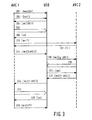
- Figure 3 illustrates how the facility to transfer menu control from one AVC to another and back again can be used to provide an integrated menu control function for a group of apparatuses in such circumstances.
- Time is represented vertically down the drawing, with actions of a User I/O subdevice (41, for example) represented in a central column, and actions of a first AVC (for example AVC 22 of the VCR 12) and a second AVC (for example AVC 20) represented to the left and right respectively.
- the device-subdevice addresses of these subdevices are represented as UIO, AVC1 and AVC2 respectively.
- Arrows represent bus requests and commands, whose names are abbreviated in the drawing, for reasons of space.
- a solid vertical line indicates menu control state Active or On in the corresponding subdevice.
- the first AVC (AVC1) has Inactive for its menu control state.
- command [menu session][on] is addressed to the User I/O subdevice, and at 302 a request [menu session?] is sent to the User I/O subdevice.
- the reply to this request at 304 indicates that a menu control session has been stated successfully between subdevices UIO and AVC1.
- the subdevice AVC1 proceeds at 306 supply a menu window specification, define menu header text, information text and item texts using the commands described above.
- the subdevice UIO displays these on the television screen and begins to supply [user entry] commands in response to the user's selection of items from the displayed menu.
- subdevice AVC1 responds to the corresponding [user entry] command by addressing a [menu control?] request to the second AVC subdevice AVC2.
- Subdevice AVC2 replies at 312 that its menu control state is Inactive.
- the first AVC sends command [menu session][transfer AVC2] to the subdevice UIO at 314, and enters the Exchanged state.
- the User I/O subdevice UIO at 316 uses command [menu control][given: AVC1] to inform the second AVC that the transfer is desired.
- the second AVC enters the Active state and at 318 initiates menu display and control with the User I/O subdevice.
- the subdevice UIO informs the second AVC that the user (having finished or aborted menu control of the corresponding apparatus) has requested a return to the previous menu. Since the previous menu was generated by an 'initiating AVC' which is not the second AVC itself, the second AVC concludes its menu control operations at 322 with a command [menu session][finished: AVC1] to the subdevice UIO, entering the Inactive state.
- the subdevice UIO uses command [menu control] [finished: AVC2] to inform the first AVC that menu control responsibility is returned to it.
- the first AVC then resumes its menu display at 326 and at 328 receives a [user entry] command which indicates the end of menu control operations.
- the first AVC therefore terminates the menu session with subdevice UIO by sending [menu session] [off] at 330.
- Menu control can be transferred repeatedly down a chain of three or more AVCS, yet with control always being returned correctly to the initiating AVC.
- each subdevice need only maintain a finite and predefined set of data within appropriate to its current state, enabling a low-cost implementation. Adding the facility to store a second set of such data would allow an AVC to take part in two menu control sessions, so that for example the 'chain' of AVCs just mentioned would be able to 'double back' to the same AVC.
Abstract
Description
- The invention relates to a local communication bus system comprising first and second apparatuses connected for the exchange of messages to a serial data channel. The invention relates in particular, but not exclusively, to a system of domestic audio and video apparatuses interconnected by a serial data channel bus for the exchange of control messages.
- A local communication bus system of the above type, configured to link a number of home electronic apparatuses for the distribution of control data and collation of apparatus current-status data, is described in European patent application EP-A-0 369 382. A television interfaced to the bus system provides a user interface, with items such as device status messages being displayed overlaying any video program currently being displayed via the television. The television controls, and more particularly a remote control unit, provide the user's input by enabling the user to select from different options displayed.
- A known serial data channel of the type referred to in the opening paragraph is provided by the Domestic Digital Bus (D2B), standardised by the International Electrotechnical Commission (IEC), Geneva. The name D2B is a trademark of Philips Electronics NV. Examples of apparatuses including D2B interfaces are Philips' model 2070 television receiver and model VR6590 video cassette recorder (VCR) previously available in Europe. Such a data channel has many applications, and it is desired that a standardised set of application protocols' be developed, in addition to the basic communication protocols defined by the IEC, and that these protocols should be adhered to by many manufacturers of consumer apparatus. In particular, the use of such protocols can bring enhanced functionality and ease of use to the great variety of consumer electronic apparatuses available today and in the future, with true inter-brand compatibility.
- The above apparatuses including D2B interfaces, for example, provide for integrated on-screen display facilities, so that a user controlling the VCR can receive information about the progress of VCR operations via the television screen. Such a feature is described in more detail in our co-pending European patent application EP-0 505 006-A2, not published at the priority date of the present application. There is a desire to integrate further the operation of the apparatuses of the system, for example to allow the user to have dialogue with an apparatus which itself has inadequate user input/output facilities. One example would be to provide menu driven control of an apparatus which itself has no means for displaying a menu, and/or no means for relating a displayed menu to input received from the user. While this is clearly possible in theory, there is an overriding cost requirement to minimise the amount of information that one apparatus must 'know' about the other apparatuses of the system. Furthermore, it is desirable for the user dialogue functions to integrate all apparatuses of the system, rather than being restricted to the control of only one apparatus in a given session.
- A prior system for remote menu display has been proposed in the "Specification of the interface between a Conditional Access Sub-System implemented as an integrated circuit card and a MAC-receiver", released by Norwegian Telecom in July 1990. While this proposal allows the IC card ("Smart card") to display a menu and receive a user selection, this depends strictly on the availability of specific marked keys on the receiver handset. The smart card is furthermore required to receive information of all user control signals (for example "volume up"), whether or not they relate to its own user dialogue. There is also no facility to integrate the user interface of many apertures of the system.
- Software interfaces for user dialogue within a single computer-controlled apparatus are also known, for example in the Apple Macintosh Computer, and the Gem User Interface Toolkit for Atari computers.
- It is an object of the invention to enable the provision of improved user dialogue features in a system of interconnected apparatuses.
- The invention provides a local communication system comprising first and second apparatuses connected for the exchange of messages to a serial data channel, the system including control means within the first apparatus and user interface means within the second apparatus, said control means including:
means for initiating a user dialogue session with the second apparatus; means for during said user dialogue session sending to the second apparatus at least one user information item for presentation to a user of the system; means for during said user dialogue session receiving from the second apparatus information which conveys user control signals; and means for controlling at least part of the system in accordance with user's wishes inferred from the said information,
said user interface means including: - means for during said user dialogue session receiving from the first apparatus user information items and presenting them to the user; means for during the user dialogue session receiving a control signal from the user; and means for sending to the first apparatus information which conveys the received user control signals,
- wherein the system further includes a third apparatus including further control means, said further control means including means for sending to the second apparatus at least one user information item, means for receiving information conveying user control signals from the second apparatus, and means for controlling at least a part of the system in accordance with user's wishes inferred from said information; characterised in that said user interface means further comprises means for identifying an association between the user control signal and one of said user information items, with the second apparatus means for sending conveying the received user control signals by reference to the associated user information item; the control means within the first apparatus further includes means for during the user dialogue session initiating a transfer of control of said session to the third apparatus; and said further control means within the third apparatus further includes means for receiving transferred control of the user dialogue session, such that the third apparatus means for sending at least one user information item, means for receiving information from the second apparatus, and means for controlling at least a part of the system will continue the transferred session without active participation by the control means within the first apparatus.
-
- By providing a transfer of control of the user dialogue session between apparatuses, the system allows integration of user dialogue functions over the system as a whole. If the manner of establishing the user dialogue session is standardised, this holds true even though the different apparatuses may come from different manufacturers. At the same time, the designers of new apparatuses for use in such a system will be constrained as little as possible by the existing features when developing new user dialogue features.
- In one embodiment, where the user dialogue session provides specifically for menu control, the user information items include items presented by the user interface means in a menu for control of the first apparatus, and the above-mentioned means for identifying an association is arranged to identify an association between a user control signal and a specific one of said menu items.
- The division of the menu control function in this manner between apparatuses allows the first apparatus to define the information content of the menu (by means of text strings or icons, for example) without regard for the style of menu presentation by the second apparatus (which might even speak the menu information to the user down a telephone line). The manner and style of selection of menu items is also unknown to the first apparatus: items might be selected by number, colour or by a movable pointer on screen. This allows maximum design independence for the manufacturers of both apparatuses.
- In an example application, a VCR (first apparatus) may initiate a user dialogue session, using the on-screen display facilities and remote control handset of a TV set (second apparatus). If the user selects to record from a channel which is scrambled (encrypted) the VCR can automatically decide to transfer the user dialogue session to a conditional access sub-system (third apparatus), in order that the user can obtain the necessary entitlement to descramble the signals for recording by the VCR. Of course the invention is not limited to a system of three apparatuses, or to any fixed configuration. The third apparatus may in turn transfer the user dialogue session to a fourth apparatus, and so on. Thus an integrated sequence of user dialogue operations can be provided spanning the functions of several apparatuses, to implement the user's wishes in a user-friendly manner, with each control means deciding freely which apparatus is in the best position to implement the user's wishes at each stage of operation.
- The above-mentioned means for initiating a user dialogue session of the first apparatus may include means for storing data identifying the second apparatus for the duration of the user dialogue session, while the user interface means within the second apparatus includes means for storing data identifying the apparatus with which it currently has a user dialogue session. In a D2B embodiment, for example, the device-subdevice address of the control means may be stored. Each apparatus can in this way limit the number of sessions in which it can become involved, and avoid interference from other apparatuses connected to the bus.
- The second apparatus in such an embodiment may act as intermediary between the first and third apparatuses in the transfer of the user dialogue session. This ensures that each apparatus need communicate only with one other in the course of its user dialogue session, no matter how many apparatuses are involved in the process as a whole. Thus small and finite data storage facilities are sufficient for each apparatus, which is important for the designer of mass-market consumer apparatuses.
- The further control means within the third apparatus may for example include means for storing data identifying the first and second apparatuses during the continuation of the user dialogue session by the third apparatus. There is thus no need for the second apparatus to remember the identity of more than one other apparatus, at least with regard to the user dialogue function.
- At the same time, each of the third and subsequent apparatuses is responsible for remembering the apparatus which transferred the user dialogue session to it, and therefore can further include means for initiating the return of the user dialogue session to that apparatus.
- Further aspects and features of the invention will be apparent from the following description.
- Embodiments of the invention will now be described, by way of example, with reference to the accompanying drawings, in which:
- Figure 1 shows a system constructed in accordance with the invention, and
- Figures 2 to 3 illustrate the operation of a menu control function in the system of Figure 1.
-
- Figure 1 shows a domestic video entertainment system comprising a
satellite broadcast tuner 10, a video cassette recorder (VCR) 12 and atelevision receiver 14, all connected to aserial data bus 16. Video and audio signals are passed within and between thedevices - The serial data bus is in this embodiment a Domestic Digital Bus (D2B) as standardised by the International Electrotechnical Commission (IEC), Geneva. D2B provides for distributed control of the bus, and allows commands and other messages to be uniquely addressed for specific "devices", such as the
apparatuses - Within each
device serial bus 16. In the physical implementation of the device, there may or may not be corresponding separate physical subdevices. In the embodiment shown, each device includes one audio/video controller (AVC) type of subdevice plus others which are logically separate and logically connected to the bus as indicated by the dotted data paths in Figure 1. The AVC subdevices provide the (distributed) controlling logic of the system as a whole, interpreting user commands and controlling the operation of the system accordingly. In the physical implementation of the device, the control logic of the AVC and some or all of the other subdevices will often be integrated using a single programmed microcontroller. Other subdevices not shown in Figure 1 will generally be included in such a system, including timers, audio amplifiers, and so forth, and the subdevices described herein are presented as a representative sample only. - In the
satellite tuner device 10, a tuner subdevice 26 (TUN) performs the signal processing functions necessary to provide baseband video signals to the connected apparatuses. TheAVC subdevice 20 receives user instructions from a user input/output (User I/O) subdevice 27 (UIO) (the front panel and/or remote control of the satellite tuner) and D2B messages from thebus 16, and operates to select channels, keep track of preset channel selections and so forth. - The
VCR device 12 includes itsAVC subdevice 22, and also a User I/O subdevice 29 (UIO), a terrestrial broadcast tuner subdevice 28 (TUN), a switchbox subdevice 30 (SB) and a videotape record/replay deck 32 (DCK). - The
television receiver device 14 includes itsAVC subdevice 24 and also a user input/output subdevice 41 (UIO), a terrestrial tuner subdevice 42 (TUN), a switchbox subdevice 44 (SB) and a video monitor subdevice 46 (VID). The User I/O subdevice 41 of the television receiver includes an on-screen display (OSD) function, as described hereinafter, and aremote control 41a for the receipt of user control signals. - In operation, the
tuner subdevices replay deck subdevice 32 can act as a source and/or a destination of video signals, depending whether it is playing and/or recording at a given time. - Since the functional elements within the
apparatuses - D2B message formats for controlling the basic functions of certain common subdevices are defined already in the IEC standard referred to above, while scope is left for defining not only new commands, but also request and reply messages that enable one D2B device or subdevice to interrogate another as to its properties and status. Each
switchbox subdevice television receiver device 14 that it is desired to watch a certain satellite broadcast channel, suitably addressed and coded D2B messages can be sent via thebus 16 to ensure that thesatellite tuner 10,VCR 12 and thetelevision 14 are active, to cause thesatellite tuner 10 to select the appropriate channel, to cause theVCR switchbox subdevice 30 and thetelevision switchbox subdevice 44 to connect the appropriate signal path from source to destination. There are many ways of arranging these events with or without user intervention. For greatest user-friendliness, the whole process can be controlled by the AVC subdevice of the device which receives the user input. The information necessary for building the signal path from source to destination can be obtained by a suitable series of D2B request messages to the relevant devices and subdevices. A suitable system for providing such control is described in GB-2 223 114-A1. In that system no AVC subdevice requires knowledge of the complete system, only its nearest neighbours. - In order to provide a user-friendly user interface for the system, any AVC subdevice (hereinafter "AVC") may wish to display user messages using the on-screen display (OSD) facility of the User I/
O subdevice 41. For example, when the television is activated by a user and a signal path set up according to the user's wishes, theAVC 24 may wish to confirm visually for the user which channel is being watched. If the signal comes from thesatellite tuner 10, a conventional on-screen display would be able to confirm no more than the fact that the signal is coming from an external connector of thetelevision 14. To allow the displayed information to include the actual channel name, known only withinAVC 20, a device information process is set up, with theAVC 24 acting as the initiating AVC andAVC 20 acting as an addressed AVC. This process is described in detail in copending European patent application EP-O 505 006-A2. - The device information process provides only a one-way flow of information, however. A user-friendly operation could be enhanced by the ability for the
VCR 12 andsatellite tuner 10 to display menus for the user using the OSD function of the User I/O subdevice 41 of thetelevision 14, and to receive the user's menu selections back from the User I/O subdevice to control further operation. To this end, menu control functions are now defined in the AVC subdevices 20 and 22, and in the User I/O subdevice 41 of the television. The menu control functions are standardised for reliable operation, but allowing as much freedom as possible for the manufacturers of the different apparatuses to provide their own style of implementation. For example, the television manufacturer might develop a particular visual style of menu, with use of special text fonts and colour-coding of menu entries, for example, while the VCR manufacturer might develop a particularly efficient and intuitively operable menu tree structure. Both of these elements can be combined by appropriate partitioning of responsibilities between subdevices in the menu control function, as described below. - Figure 2 shows a standardised menu window layout, of the type that can be generated in the embodiment described. The menu window 200 is divided into a header filed 210, an
information field 212 and aselection field 214. The header field has room for a single line oftext 216, of a length W characters, which text is defined by a string of W character codes in accordance with a standard character set. The information field contains room for a number H1 of lines of W text characters, and can be used by the AVC to give instructions to the user. - The
selection field 214 has room for a number H2 of items for user selection. The AVC provides a text string of W-4 characters to identify the item to the user. The leftmost four characters are available for the User I/O subdevice to show selectionkey information 218 for each item. Thus in the embodiment described, there might be buttons marked 'a', 'b', 'c', 'd' and 'e' on theremote control handset 41a of thetelevision 14, and the User I/O subdevice 41 recognises these buttons as selectors of the five displayed menu items. Alternative embodiments might use other symbols, or colour coding as the selection key information. - For the purposes of menu control functions, the present embodiment distinguishes between the functions of an AVC subdevice and a User I/O subdevice, and defines the means of cooperation between the two subdevices.
- With regard to menu control the AVC subdevice has three states: Inactive, Active and Exchanged. In the Inactive state, the AVC is currently not engaged in a menu control session. In the Active state, the AVC is currently engaged in a menu control session on a certain User I/O subdevice or it is trying to establish a menu control session with a User I/O subdevice. In the Exchanged state the AVC is engaged in a menu control session, but one of the generated menus has given the user the ability to transfer menu control to another device, and the right of menu control has transferred to the AVC subdevice of that device.
- Since it is assumed that an AVC can have only one menu control session active at one time, each AVC is only able to start a menu control session if it is in the Inactive state. In the other states the AVC will not start a menu control session when requested by a local event or a [menu][on] command, described below.
- As far as menu control is concerned, an AVC maintains the following data items:
- State -
- Inactive, Active, or Exchanged
- Initiating AVC -
- Device-subdevice address of the AVC subdevice that initiated the menu control session, if applicable. This could be the AVC itself in case of e.g. a local event.
- Transferred AVC -
- Device-subdevice address of the AVC subdevice to which menu control has been transferred, if applicable.
- User I/O -
- Device-subdevice address of the User I/O subdevice on which the menu control session is running.
- With regard to menu control the User I/O subdevice has three states, Off, On and Transferring. In the Off state, no menu is displayed. In the On state, one menu is currently displayed or is about to be displayed. In the Transferring state, the User I/O subdevice is transferring menu control from one AVC to another AVC. Since it is assumed that an User I/O subdevice can display only one menu at a time, it can only start a menu control session if it is in the Off state. If the User I/O subdevice has its menu control function in the On state, then it will not start another menu control session.
- As far as menu control is concerned, an User I/O subdevice maintains the following data:
- Current state -
- On, Off or Transferring.
- Current AVC -
- Device-subdevice address of the AVC which currently has a menu control session (that is it may define a menu) with the User I/O subdevice, and to which user commands regarding menu control will be sent.
- Window specification -
- The User I/O subdevice knows whether a window specification has been received or not. For the details of the window specification see the description of the command [define menu window] below.
- Menu items -
- The User I/O knows all menu items which have been defined and their current status as far as user input/control is concerned. For details of the data for each item see the description of the commands [define menu item] and [user entry] below.
- The command messages defined to allow implementation of the menu control function via D2B will now be described, to be followed by a brief illustration of their use in practical operation.
- A Menu Control command [menu control][state] is defined for use by a User I/O subdevice to exchange the right of menu control from one AVC to another AVC. Three different [state] parameters are defined: [given], which includes the device-subdevice address of an initiating AVC; [finished], which includes the address of a current AVC; and [aborted], which includes the address of a current AVC.
- If the [menu control][given] command is received by an AVC which is in the Inactive state, then the addressed AVC goes to the Active state, stores the device-subdevice address specified in the command as the initiating AVC, stores the device-subdevice address of the User I/O subdevice which sent this command as the current User I/O, and starts menu control on that User I/O subdevice. When menu control is finished (for example the AVC/user decides to stop menu control), the addressed AVC returns menu control to the initiating AVC via the current User I/O subdevice with a [menu session][finished] command, described below.
- If the [menu control][given] command is received by an AVC which is in the Active state or in the Exchanged state, then the addressed AVC does not start a second menu control session but returns the right of menu control to the specified initiating AVC via the current User I/O subdevice with a [menu session][aborted] command, described below.
- If the [menu control][finished] command is received while the AVC is in the Exchanged state, then the addressed AVC goes to the Active state, stores the device-subdevice address of the User I/O subdevice that sent this command as the current User I/O and resumes menu control on that User I/O subdevice. The specified current AVC is the AVC which finished its menu control and returned the right of menu control to the AVC which received this command.
- If the [menu control][aborted] command is received while the AVC is in the Exchanged state, then the addressed AVC goes to the Active state, stores the device-subdevice address of the User I/O subdevice that sent this command as the current User I/O and resumes menu control on that User I/O subdevice. The specified current AVC indicates the AVC which was asked to start menu control but was not able to do so and therefore aborted.
- A Menu Session command [menu session][parameter] is defined for use by an AVC to start or stop a menu control session with the OSD function of a User I/O subdevice or to transfer a menu control session to another AVC. The parameter field can take the value [off], [on], [transfer], [finished] or [aborted]. The value [transfer] includes the address of a new AVC. Values [finished] and [aborted] include the address of an initiating AVC.
- If the [menu session][off] command is received while the menu control function of the User I/O subdevice is in the On state and the device-subdevice address of the AVC which sent this command is the same as that stored as the current AVC, then the menu control function goes to the Off state.
- If the [menu session][on] command is received while the menu control function of the User I/O subdevice is in the Off state, then the menu control function goes to the On state and the device-subdevice address of the AVC which sent this command is stored as the current AVC. The User I/O subdevice also memorises that a window specification has not yet been received and it clears the list of menu items. If the [menu session][on] command is received while the menu control function of the User I/O subdevice is in the On state or Transferring state, then the User I/O subdevice disregards this command, since it can store data for only one session at a time.
- If the [menu session][transfer] command is received from the current AVC while the menu control function of the User I/O subdevice is in the On state, then the User I/O subdevice goes to the Transferring state where it transfers menu control from the current AVC to the new AVC subdevice specified in the command, by issuing a command [menu control][given] to the new AVC. If this command is transmitted successfully, the menu control function of the User I/O subdevice goes to the On state and replaces the device-subdevice address stored as the current AVC with the address of the new AVC. If the command transmission was not successful, the User I/O subdevice issues a command [menu control][aborted] to the current AVC and goes to the On state. It also memorises in either case that a window specification has not yet been received and clears its list of menu items.
- If the [menu session][finished] command is received from the current AVC while the menu control function of the User I/O subdevice is in the On state, then the User I/O subdevice goes to the Transferring state where it transfers menu control from the current AVC to the specified initiating AVC. The User I/O subdevice issues a command [menu control][finished] to the specified initiating AVC. If this command is transmitted successfully, the menu control function of the User I/O subdevice goes to the On state, and replaces the device-subdevice address stored as the current AVC with the address of the specified initiating AVC. It also memorises that a window specification has not yet been received and it clears the list of menu items. If the command transmission was not successful, the User I/O menu control function goes to the Off state.
- If the [menu session][aborted] command is received from the current AVC while the menu control function of the User I/O subdevice is in the On state, then the User I/O subdevice goes to the Transferring state where it returns menu control from the current AVC to the specified initiating AVC. The User I/O subdevice issues a command [menu control][aborted] to the specified initiating AVC. If this command is transmitted successfully, the menu control function of the User I/O subdevice goes to the On state, and replaces the device-subdevice address stored as the current AVC with the address of the specified initiating AVC, It also memorises that a window specification has not yet been received and clears the list of menu items. If the command transmission was not successful, the menu control function of the User I/O subdevice goes to the Off state.
- A Menu Entry command [menu entry][operand] is defined for use by a User I/O subdevice to inform an AVC subdevice that the user has entered a command to start, stop or restart menu control. The operand can take the value [off],[on],[repeat] or [previous].
- When the user indicates a desire to start menu control, the menu control function of the User I/O subdevice will send the command [menu entry][on] to the AVC subdevice stored. When the user has requested return to a previous menu, then the menu control function will send the command [menu entry][previous] to the AVC subdevice. If the current menu of the menu control session has been garbled, corrupted or overwritten by the User I/O subdevice and the menu has to be re-displayed, then the last displayed menu can be asked for by sending a [menu entry][repeat] command to the current AVC subdevice. When the user indicates a desire to end menu control while the menu control function of the User I/O subdevice is in the On state, then the menu control function will send the command [menu entry][off] to the AVC subdevice stored as the current AVC.
- If an AVC subdevice receives the command [menu entry][off] while it is in the Active or Exchanged state, and the AVC device-subdevice address stored as initiating AVC is equal to its own device-subdevice address, then the AVC subdevice will send a command [menu session][off] to the User I/O subdevice stored and then the menu control function goes to the Inactive state (i.e. the AVC subdevice stops the generation of menus). If an AVC subdevice receives the command [menu entry][off] while it is in the Active or Exchanged state, and the AVC device-subdevice address stored as initiating AVC is not equal to its own device-subdevice address, then the AVC subdevice will send a D2B command [menu session][finished] to the User I/O subdevice stored and then the menu control function goes to the Inactive state (i.e. the AVC subdevice stops the generation of menus).
- If the AVC subdevice receives the command [menu entry][on] while it is in the Inactive state, then the menu control function goes to the Active state, stores the device-subdevice address of the User I/O subdevice which sent this command, starts a menu control session with the menu control function of that User I/O subdevice and starts menu control at its main menu.
- If an AVC subdevice receives the command [menu entry] [previous] while it is in the Active state, then the following applies. If the menu control feature is not in the main menu, then it goes to the previous menu (e.g. it goes up one step in the menu tree). If the menu control feature is in the main menu, and the AVC device-subdevice address stored as initiating AVC is different from its own device-subdevice address (i.e. the menu control feature has been started by an external AVC subdevice via an User I/O subdevice with a [menu control][given] command), then the AVC subdevice sends a [menu session][finished] command to the current User I/O subdevice and then goes to the Inactive state. Otherwise it stops the menu control session on the User I/O subdevice stored with a [menu session][off] command.
- If an AVC subdevice receives the command [menu entry][repeat] while it is in the Inactive state, then the menu control function goes to the Active state, stores the device-subdevice address of the User I/O subdevice which sent this command, starts a menu control session with the menu control function of the User I/O subdevice and restarts menu control at its current menu (i.e. the menu last sent). If an AVC subdevice receives the command [menu entry][repeat] while it is in the Active state, then the menu control function redefines its current menu (i.e. the menu last sent) to the menu control function of the User I/O subdevice stored.
- A Define Menu Window command [define menu window][window specification] is defined for use by an AVC to propose a menu that may fit in the menu window provided by the menu control function of the User I/O subdevice. The parameter [window specification] contains information defining the proposed menu format, including:
- whether the menu is a main menu or a normal menu, that is whether it is possible to go higher in the 'menu tree' by means of a command [menu entry][previous];
- the width W in characters of the menu header and menu information fields 210 and 212;
- the number of lines in the
information field 212; - the width in characters of each item, allowing space for
the
key information 218, to be defined by the User I/O subdevice; and - a list of item types, including as many item types as there are to be items in the menu.
- Several different item types may be defined in addition to the simple selectable items illustrated in Figure 2. For example 'slider' controls for volume, brightness levels etc. can be provided, and items which allow entry of numeric items such as radio frequencies and personal identification codes. When a User I/O subdevice receives this command, it verifies if it is in the On state and if the device-subdevice address of the stored AVC is equal to the device-subdevice address of the AVC which sent this command, and if the required menu specification can be displayed in the menu window supported.
- A Display Menu Header command [display menu header][text string] is defined for use by an AVC (the AVC which is known to the User I/O as having the right of menu control) to send text for the
menu header field 210 to the User I/O subdevice. Similarly, a Display Menu Text command [display menu text][text string] is defined for uses by the AVC to send text for theinformation field 212. - A Display Menu Item command [display menu item][item number][item specification] is defined for the current AVC to send a text field and other parameters of the item to the User I/O subdevice. Where different types of menu item are possible, the field [item specification] should reflect correctly the item type of the item identified by the field [item number], as defined in the list of item types in the previously supplied window specification. The field [item specification] also specifies for example when and how feedback is to be supplied to the AVC in response to user actions by means of the command [user entry] described elsewhere.
- A User Entry command [user entry][item number][select state] is defined, for use by a User I/O subdevice to return a user entry to the stored AVC. Each [user entry] command defines the updated state (for example: selected or de-selected) of the menu item identified by the [item number] operand. As far as the User I/O subdevice is concerned, several items can be in the selected state at one time. Other operands are defined for the other item types such as sliders and numeric entry items.
- Also defined are request messages [menu control?], [menu session?] and [menu window?]. Request [menu control?] can be addressed to an AVC to find out the state of its menu control function: Active, Inactive or Exchanged. A reply [Active] will also specify the initiating AVC (which can be the addressed AVC itself) and the current User I/O as known to the addressed AVC. A reply [Exchanged] will also specify the initiating AVC and the transferred AVC. Request [menu session?] performs a similar function when addressed to a User I/O subdevice, which will reply [On],[Off] or [Transferring]. The reply [On] will specify the current AVC, while the reply [Transferring] specifies both the current AVC and the new AVC. The request [menu window?] is used by an AVC which has sent a window specification (see Define Menu Window command) to find out if the User I/O subdevice can display the specified menu. If the reply is that the User I/O subdevice cannot display the specified menu, the reply contains a specification of a window that is possible, in terms of width, number of items and so forth.
- The operation of the menu control functions of the system of Figure 1 will now be illustrated by the examples of Figures 2 and 3.
- In the operation of the menu control functions of the system there are basically three alternative events which can give rise to the start of a menu control session:
- an AVC starts menu control due to a local event (for example end of tape, user presses a key on the local keyboard, or the need for authorization in case of conditional access);
- the user wants to start menu control via a User I/O subdevice (for example he/she presses a 'start menu control' button on the remote control hand set) and
- an AVC which shows a menu, has as one of the options to transfer menu control to another device (for example one of the menus of the television allows menu control to be transferred to the VCR).
- When, due to a local event such as end of tape in the
VCR 12, the AVC 22 (for example) wants to start menu control, it simply starts a session with the menu control function of the User I/O subdevice 41, by sending a [menu session][on] command. The AVC then defines the menu window and items therein, and receives the user's menu selections from the User I/O subdevice. When the menu control has finished, theAVC 22 releases the menu control session in the User I/O subdevice 41 with a [menu session][off] command. This might happen due to the user ending menu control (which is then indicated to the AVC with a [menu entry][off] command) or due to a local event (for example no user response on the current menu for a certain period of time, or the user puts the device in standby using local keys). - It may be in the course of menu control operations that one of the items selected on the menu generated by the
AVC 22 of theVCR 12 relates for example to the recording of a programme from thesatellite tune 10. This may involve channel selection in the satellite tuner, and also operations for obtaining conditional access authorisation (pay-as-you-view television). Clearly, for a consistent menu-based user interaction, it is desirable that such operations can be performed by the user with a view of the system as an integrated whole, without concern as to whether this menu or that affects one apparatus or another (or all of them). At the same time, it is impracticable to expect the AVC 22 (for example) to know the menus and actions required to control all apparatuses in the system, particularly in view of the fact that these apparatuses can be added to the system at any time, and may come from different manufacturers. - Figure 3 illustrates how the facility to transfer menu control from one AVC to another and back again can be used to provide an integrated menu control function for a group of apparatuses in such circumstances. Time is represented vertically down the drawing, with actions of a User I/O subdevice (41, for example) represented in a central column, and actions of a first AVC (for
example AVC 22 of the VCR 12) and a second AVC (for example AVC 20) represented to the left and right respectively. The device-subdevice addresses of these subdevices are represented as UIO, AVC1 and AVC2 respectively. Arrows represent bus requests and commands, whose names are abbreviated in the drawing, for reasons of space. A solid vertical line indicates menu control state Active or On in the corresponding subdevice. - At the start of the sequence of Figure 3, the first AVC (AVC1) has Inactive for its menu control state. At 300, command [menu session][on] is addressed to the User I/O subdevice, and at 302 a request [menu session?] is sent to the User I/O subdevice. The reply to this request at 304 indicates that a menu control session has been stated successfully between subdevices UIO and AVC1. The subdevice AVC1 proceeds at 306 supply a menu window specification, define menu header text, information text and item texts using the commands described above. The subdevice UIO then displays these on the television screen and begins to supply [user entry] commands in response to the user's selection of items from the displayed menu.
- In the course of these operations, an item is selected which requires transfer of menu control to subdevice AVC2. The subdevice AVC1 responds to the corresponding [user entry] command by addressing a [menu control?] request to the second AVC subdevice AVC2. Subdevice AVC2 replies at 312 that its menu control state is Inactive. The first AVC sends command [menu session][transfer AVC2] to the subdevice UIO at 314, and enters the Exchanged state. The User I/O subdevice UIO at 316 uses command [menu control][given: AVC1] to inform the second AVC that the transfer is desired.
- Assuming a successful transfer, the second AVC enters the Active state and at 318 initiates menu display and control with the User I/O subdevice. At 320, the subdevice UIO informs the second AVC that the user (having finished or aborted menu control of the corresponding apparatus) has requested a return to the previous menu. Since the previous menu was generated by an 'initiating AVC' which is not the second AVC itself, the second AVC concludes its menu control operations at 322 with a command [menu session][finished: AVC1] to the subdevice UIO, entering the Inactive state.
- At 324 the subdevice UIO uses command [menu control] [finished: AVC2] to inform the first AVC that menu control responsibility is returned to it. The first AVC then resumes its menu display at 326 and at 328 receives a [user entry] command which indicates the end of menu control operations. The first AVC therefore terminates the menu session with subdevice UIO by sending [menu session] [off] at 330.
- Of course an infinite range of eventualities are possible in a real system, which can be handled in a consistent manner thanks to the predefined meaning of the bus commands and requests defined above. Menu control can be transferred repeatedly down a chain of three or more AVCS, yet with control always being returned correctly to the initiating AVC. At the same time, each subdevice need only maintain a finite and predefined set of data within appropriate to its current state, enabling a low-cost implementation. Adding the facility to store a second set of such data would allow an AVC to take part in two menu control sessions, so that for example the 'chain' of AVCs just mentioned would be able to 'double back' to the same AVC.
- From reading the present disclosure, other modifications will be apparent to persons skilled in the art, and the applicants hereby give notice that the scope of the present invention is to be determined solely by the following claims. Such modifications may involve other features which are already known in the design, manufacture and use of local communication systems, domestic audio/video apparatuses and component parts thereof and which may be used instead of or in addition to features described in the foregoing example. For example, there are possible forms of user dialogue other than menu control. Also there are many possible forms of serial data channel other than D2B: the data channels may, for example, be provided via copper wire, optical fibre or wireless links.
Claims (8)
- A local communication system comprising first (12) and second (14) apparatuses connected for the exchange of messages to a serial data channel (16), the system including control means (22) within the first apparatus and user interface means (41) within the second apparatus, said control means (22) including:
means for initiating a user dialogue session with the second apparatus (14); means for during said user dialogue session sending to the second apparatus at least one user information item for presentation to a user of the system; means for during said user dialogue session receiving from the second apparatus information which conveys user control signals; and means for controlling at least part of the system in accordance with user's wishes inferred from the said information,
said user interface means (41) including:characterised in that said user interface means further comprises means for identifying an association between the user control signal and one of said user information items, with the second apparatus means for sending conveying the received user control signals by reference to the associated user information item; the control means (22) within the first apparatus (12) further includes means for during the user dialogue session initiating a transfer of control of said session to the third apparatus (10); and said further control means within the third apparatus (20) further includes means for receiving transferred control of the user dialogue session, such that the third apparatus means for sending at least one user information item, means for receiving information from the second apparatus, and means for controlling at least a part of the system will continue the transferred session without active participation by the control means within the first apparatus.means for during said user dialogue session receiving from the first apparatus (12) user information items and presenting them to the user; means for during the user dialogue session receiving a control signal from the user; and means for sending to the first apparatus (12) information which conveys the received user control signals,wherein the system further includes a third apparatus (10) including further control means (20), said further control means (20) including means for sending to the second apparatus at least one user information item, means for receiving information conveying user control signals from the second apparatus, and means for controlling at least a part of the system in accordance with user's wishes inferred from said information; - A system as claimed in Claim 1 wherein the user information items include items presented by the user interface means (41) in a menu for control of the first apparatus (12), and wherein the said means for identifying an association is arranged to identify an association between a user control signal and a specific one of said menu items.
- A system as claimed in Claim 1 or 2 wherein the said means for initiating a user dialogue session of the first apparatus includes means for storing data identifying the second apparatus (14) for the duration of the user dialogue session and wherein the second apparatus includes means for storing data identifying the apparatus with which it currently has a user dialogue session.
- A system as claimed in Claim 3 wherein the second apparatus (14) acts as intermediary between the first (12) and third (10) apparatuses in the transfer of the user dialogue session.
- A system as claimed in Claim 3 or 4 wherein the said means for receiving transferred control of the user dialogue session of the third apparatus (10) includes means for storing data identifying the first and second apparatuses during the continuation of the user dialogue session by the third apparatus.
- A system as claimed in Claim 3, 4 or 5 yet further including a fourth apparatus, wherein the control means (20) of the third apparatus (10) further includes means for during the user dialogue session initiating a further transfer of the user dialogue session to the fourth apparatus.
- A system as claimed in Claim 3, 4, 5 or 6 wherein the control means (20) of the third apparatus further includes means for initiating the return of the user dialogue session to the first apparatus (12).
- A system as claimed in any preceding claim wherein the or each control means (20,22,24) and the user interface means (41) are individually addressable via the serial data channel (16) as a control subdevice and user interface subdevice respectively, the stored data identifying each such means comprising its subdevice address.
Applications Claiming Priority (2)
| Application Number | Priority Date | Filing Date | Title |
|---|---|---|---|
| GB9121203 | 1991-10-04 | ||
| GB919121203A GB9121203D0 (en) | 1991-10-04 | 1991-10-04 | Local communication bus system and apparatus for use in such a system |
Publications (3)
| Publication Number | Publication Date |
|---|---|
| EP0535749A2 EP0535749A2 (en) | 1993-04-07 |
| EP0535749A3 EP0535749A3 (en) | 1995-05-24 |
| EP0535749B1 true EP0535749B1 (en) | 1999-07-07 |
Family
ID=10702497
Family Applications (1)
| Application Number | Title | Priority Date | Filing Date |
|---|---|---|---|
| EP92202992A Expired - Lifetime EP0535749B1 (en) | 1991-10-04 | 1992-09-30 | Local communication bus system |
Country Status (8)
| Country | Link |
|---|---|
| US (1) | US5574965A (en) |
| EP (1) | EP0535749B1 (en) |
| JP (1) | JP3300794B2 (en) |
| KR (1) | KR100251607B1 (en) |
| AT (1) | ATE182037T1 (en) |
| DE (1) | DE69229529T2 (en) |
| FI (1) | FI112571B (en) |
| GB (1) | GB9121203D0 (en) |
Cited By (22)
| Publication number | Priority date | Publication date | Assignee | Title |
|---|---|---|---|---|
| US6118724A (en) | 1997-04-30 | 2000-09-12 | Canon Kabushiki Kaisha | Memory controller architecture |
| US6195674B1 (en) | 1997-04-30 | 2001-02-27 | Canon Kabushiki Kaisha | Fast DCT apparatus |
| US6259456B1 (en) | 1997-04-30 | 2001-07-10 | Canon Kabushiki Kaisha | Data normalization techniques |
| US6311258B1 (en) | 1997-04-03 | 2001-10-30 | Canon Kabushiki Kaisha | Data buffer apparatus and method for storing graphical data using data encoders and decoders |
| US6336180B1 (en) | 1997-04-30 | 2002-01-01 | Canon Kabushiki Kaisha | Method, apparatus and system for managing virtual memory with virtual-physical mapping |
| US6707463B1 (en) | 1997-04-30 | 2004-03-16 | Canon Kabushiki Kaisha | Data normalization technique |
| US7917933B2 (en) | 2000-10-11 | 2011-03-29 | United Video Properties, Inc. | Systems and methods for relocating media |
| US8086575B2 (en) | 2004-09-23 | 2011-12-27 | Rovi Solutions Corporation | Methods and apparatus for integrating disparate media formats in a networked media system |
| US8254455B2 (en) | 2007-06-30 | 2012-08-28 | Microsoft Corporation | Computing collocated macroblock information for direct mode macroblocks |
| US8607287B2 (en) | 2005-12-29 | 2013-12-10 | United Video Properties, Inc. | Interactive media guidance system having multiple devices |
| US8646005B2 (en) | 1996-05-03 | 2014-02-04 | Starsight Telecast, Inc. | Information system |
| US8850499B2 (en) | 2000-10-11 | 2014-09-30 | United Video Properties, Inc. | Systems and methods for caching data in media-on-demand systems |
| US9014546B2 (en) | 2009-09-23 | 2015-04-21 | Rovi Guides, Inc. | Systems and methods for automatically detecting users within detection regions of media devices |
| US9021538B2 (en) | 1998-07-14 | 2015-04-28 | Rovi Guides, Inc. | Client-server based interactive guide with server recording |
| US9113122B2 (en) | 1997-04-21 | 2015-08-18 | Rovi Guides, Inc. | Method and apparatus for time-shifting video and text in a text-enhanced television program |
| US9125169B2 (en) | 2011-12-23 | 2015-09-01 | Rovi Guides, Inc. | Methods and systems for performing actions based on location-based rules |
| US9161087B2 (en) | 2000-09-29 | 2015-10-13 | Rovi Technologies Corporation | User controlled multi-device media-on-demand system |
| US9191722B2 (en) | 1997-07-21 | 2015-11-17 | Rovi Guides, Inc. | System and method for modifying advertisement responsive to EPG information |
| US9307278B2 (en) | 2000-03-31 | 2016-04-05 | Rovi Guides, Inc. | Systems and methods for reducing cut-offs in program recording |
| US9319735B2 (en) | 1995-06-07 | 2016-04-19 | Rovi Guides, Inc. | Electronic television program guide schedule system and method with data feed access |
| US9326016B2 (en) | 2007-07-11 | 2016-04-26 | Rovi Guides, Inc. | Systems and methods for mirroring and transcoding media content |
| US9426509B2 (en) | 1998-08-21 | 2016-08-23 | Rovi Guides, Inc. | Client-server electronic program guide |
Families Citing this family (74)
| Publication number | Priority date | Publication date | Assignee | Title |
|---|---|---|---|---|
| US5210846B1 (en) * | 1989-05-15 | 1999-06-29 | Dallas Semiconductor | One-wire bus architecture |
| US6003770A (en) * | 1992-10-06 | 1999-12-21 | Interdigital Technology Corporation | Wireless telephone debit card system and method |
| US5488357A (en) * | 1993-01-06 | 1996-01-30 | Sony Corporation | Remote controlling method and system feature starting method and controlling method for audio/visual system |
| WO1994028674A1 (en) * | 1993-05-28 | 1994-12-08 | Sony Corporation | Method for connecting av equipment to av system |
| GB9313396D0 (en) * | 1993-06-29 | 1993-08-11 | Link Res Ltd | Television apparatus |
| GB9404873D0 (en) * | 1993-10-02 | 1994-04-27 | Amulet Electronics Ltd | Television broadcast distribution systems |
| US5734786A (en) * | 1993-10-20 | 1998-03-31 | E Guide, Inc. | Apparatus and methods for deriving a television guide from audio signals |
| KR950016212A (en) * | 1993-11-17 | 1995-06-17 | 이헌조 | Video device with game function |
| GB9325299D0 (en) * | 1993-12-10 | 1994-02-16 | D2B Systems Co Ltd | Local communication system and station for use in as system |
| GB9325301D0 (en) * | 1993-12-10 | 1994-02-16 | D2B Systems Co Ltd | Local communication system and station for use in such a system |
| GB9325300D0 (en) * | 1993-12-10 | 1994-02-16 | D2B Systems Co Ltd | Local communication system and station for use in such a system |
| DE69418300T2 (en) * | 1994-02-22 | 1999-11-04 | Koninkl Philips Electronics Nv | Method of transferring image data from a sender to a selected recipient |
| FR2726720B1 (en) * | 1994-11-04 | 1997-01-03 | Thomson Consumer Electronics | METHOD FOR DETECTING SCART TYPE CONNECTIONS IN A HOME AUTOMATION NETWORK |
| US6341195B1 (en) * | 1994-12-28 | 2002-01-22 | E-Guide, Inc. | Apparatus and methods for a television on-screen guide |
| US20020010918A1 (en) * | 1994-12-28 | 2002-01-24 | E-Guide, Inc. | Apparatus and methods for a television on-screen guide |
| DE69633877T2 (en) * | 1995-07-28 | 2005-11-03 | Sony Corp. | Control of an electronic system |
| US5815297A (en) * | 1995-10-25 | 1998-09-29 | General Instrument Corporation Of Delaware | Infrared interface and control apparatus for consumer electronics |
| JP3309720B2 (en) * | 1996-06-25 | 2002-07-29 | ソニー株式会社 | Video system control method |
| DE19625901A1 (en) * | 1996-06-27 | 1998-01-08 | Siemens Ag | Methods and arrangements for the optimal use of switching and transmission resources of multimedia communication networks |
| JP3577845B2 (en) | 1996-07-25 | 2004-10-20 | 松下電器産業株式会社 | TV monitor device |
| US5787335A (en) * | 1996-11-18 | 1998-07-28 | Ethnic-American Broadcasting Co, Lp | Direct broadcast satellite system for multiple dwelling units |
| JP4114970B2 (en) | 1997-03-24 | 2008-07-09 | ソニー株式会社 | Information signal transmission device |
| GB9706620D0 (en) * | 1997-04-01 | 1997-05-21 | Sgs Thomson Microelectronics | A method for remotely controlling a plurality of apparatus using a single remote control device |
| US6421069B1 (en) | 1997-07-31 | 2002-07-16 | Sony Corporation | Method and apparatus for including self-describing information within devices |
| DE19740712C2 (en) * | 1997-09-16 | 2000-12-07 | Siemens Ag | Bus system for building networking |
| GB2332345B (en) * | 1997-12-09 | 2002-12-11 | Sony Uk Ltd | A digital video receiver a conditional access module and a method of transmitting data therebetween |
| DE19757239B4 (en) * | 1997-12-22 | 2010-11-11 | Deutsche Thomson-Brandt Gmbh | Uniform menu navigation of consumer electronics |
| JP3365298B2 (en) * | 1998-02-27 | 2003-01-08 | 松下電器産業株式会社 | Video signal recording and playback device |
| FR2777140A1 (en) * | 1998-04-07 | 1999-10-01 | Philips Electronics Nv | AUDIOVISUAL SYSTEM CONSISTING OF SEVERAL DEVICES, SOME OF WHICH ARE CONSTITUTED OF SEVERAL FUNCTIONAL MODULES |
| JP4248028B2 (en) * | 1998-04-22 | 2009-04-02 | コーニンクレッカ フィリップス エレクトロニクス エヌ ヴィ | Function management in consumer electronic systems |
| US6233611B1 (en) | 1998-05-08 | 2001-05-15 | Sony Corporation | Media manager for controlling autonomous media devices within a network environment and managing the flow and format of data between the devices |
| FR2779595B1 (en) | 1998-06-08 | 2000-07-21 | Thomson Multimedia Sa | METHOD FOR MANAGING PRIORITIES FOR ACCESS TO RESOURCES IN A HOME NETWORK AND APPARATUS FOR IMPLEMENTING SAME |
| FR2779596B1 (en) * | 1998-06-08 | 2000-07-21 | Thomson Multimedia Sa | METHOD FOR SCHEDULING RESOURCE ACTIONS IN A HOME COMMUNICATION NETWORK |
| AR020608A1 (en) | 1998-07-17 | 2002-05-22 | United Video Properties Inc | A METHOD AND A PROVISION TO SUPPLY A USER REMOTE ACCESS TO AN INTERACTIVE PROGRAMMING GUIDE BY A REMOTE ACCESS LINK |
| CN101383947B (en) | 1998-07-17 | 2012-08-01 | 联合视频制品公司 | Method for access to and providing programme by remote access link |
| US6820278B1 (en) * | 1998-07-23 | 2004-11-16 | United Video Properties, Inc. | Cooperative television application system having multiple user television equipment devices |
| US6859799B1 (en) | 1998-11-30 | 2005-02-22 | Gemstar Development Corporation | Search engine for video and graphics |
| US6731347B1 (en) | 1999-04-09 | 2004-05-04 | Sony Corporation | Method for switching signal input based on device capability |
| AU4208600A (en) * | 1999-04-09 | 2000-11-14 | Sony Electronics Inc. | Method for switching signal input based on device capability |
| US6826776B1 (en) | 1999-04-09 | 2004-11-30 | Sony Corporation | Method and apparatus for determining signal path |
| AU4076300A (en) * | 1999-04-09 | 2000-11-14 | Sony Electronics Inc. | Method and apparatus for controlling connections between devices |
| US6976267B1 (en) | 1999-04-09 | 2005-12-13 | Sony Corporation | Method and apparatus for controlling connections between devices |
| US6757025B1 (en) | 1999-04-09 | 2004-06-29 | Sony Corporation | Method for switching input terminals based on incoming signal format |
| DE19926361A1 (en) * | 1999-06-10 | 1999-09-30 | Grundig Ag | Television receiver with menu-guided basic setting up |
| US6988276B2 (en) * | 1999-12-14 | 2006-01-17 | Koninklijke Philips Electronics N.V. | In-house TV to TV channel peeking |
| ES2253389T3 (en) * | 2000-01-07 | 2006-06-01 | Qualcomm Incorporated | SYSTEM AND PROCEDURE TO CONNECT DOMESTIC DEVICES OF ENTERTAINMENT AND INFORMATICS THROUGH A LOCAL NETWORK BASED ON CDMA. |
| GB0003306D0 (en) * | 2000-02-15 | 2000-04-05 | Koninkl Philips Electronics Nv | Control of interconnected audio/video devices |
| JP2001282701A (en) * | 2000-03-31 | 2001-10-12 | Aiwa Co Ltd | Device and method for processing information |
| US6802830B1 (en) * | 2000-06-16 | 2004-10-12 | Drew Waters | Device and method that generates a fog capable of altering the color of human skin |
| KR100375567B1 (en) * | 2000-08-14 | 2003-03-15 | 주식회사 금영 | System for managing karaokes separately |
| US6686838B1 (en) | 2000-09-06 | 2004-02-03 | Xanboo Inc. | Systems and methods for the automatic registration of devices |
| US7555528B2 (en) | 2000-09-06 | 2009-06-30 | Xanboo Inc. | Systems and methods for virtually representing devices at remote sites |
| US7734724B2 (en) * | 2000-09-06 | 2010-06-08 | Xanboo Inc. | Automated upload of content based on captured event |
| EP1199847A1 (en) * | 2000-10-20 | 2002-04-24 | Deutsche Thomson-Brandt Gmbh | Method for the data exchange between network devices |
| US6658386B2 (en) * | 2000-12-12 | 2003-12-02 | International Business Machines Corporation | Dynamically adjusting speech menu presentation style |
| JP4104300B2 (en) * | 2001-06-25 | 2008-06-18 | 三洋電機株式会社 | Multiple equipment control system |
| US20040251887A1 (en) * | 2001-09-20 | 2004-12-16 | Sparrell Carlton J | Centralized resource manager with power switching system |
| US7352991B2 (en) * | 2002-03-21 | 2008-04-01 | National Antenna Systems | Satellite signal distribution systems |
| US7493646B2 (en) | 2003-01-30 | 2009-02-17 | United Video Properties, Inc. | Interactive television systems with digital video recording and adjustable reminders |
| US20060051059A1 (en) | 2004-09-08 | 2006-03-09 | Krakirian Haig H | Video recorder having user extended and automatically extended time slots |
| US20070226344A1 (en) * | 2004-07-23 | 2007-09-27 | General Instrument Corporation | Centralized Resource Manager With Power Switching System |
| US7339492B1 (en) * | 2004-10-04 | 2008-03-04 | Matthew David Alexander | Multi-media wireless system |
| KR100603293B1 (en) * | 2004-10-20 | 2006-07-24 | 삼성전자주식회사 | Audio/Video apparatus for visualizing operations therein, or thereamong in the form of contents flow and a method operation controlling thereof |
| US9973817B1 (en) | 2005-04-08 | 2018-05-15 | Rovi Guides, Inc. | System and method for providing a list of video-on-demand programs |
| US20070079342A1 (en) | 2005-09-30 | 2007-04-05 | Guideworks, Llc | Systems and methods for managing local storage of on-demand content |
| KR20070048060A (en) * | 2005-11-03 | 2007-05-08 | 삼성전자주식회사 | Broadcasting signal recording/playing system, broadcasting signal recording/playing apparatus, broadcasting signal tuning apparatus |
| JP2007134928A (en) * | 2005-11-10 | 2007-05-31 | Renesas Technology Corp | Rf analog signal processing unit and mobile terminal device with mounted signal processing unit |
| US9681105B2 (en) | 2005-12-29 | 2017-06-13 | Rovi Guides, Inc. | Interactive media guidance system having multiple devices |
| EP2091228A4 (en) * | 2006-12-08 | 2012-12-19 | Panasonic Corp | Remote control system |
| US7801888B2 (en) | 2007-03-09 | 2010-09-21 | Microsoft Corporation | Media content search results ranked by popularity |
| US10063934B2 (en) | 2008-11-25 | 2018-08-28 | Rovi Technologies Corporation | Reducing unicast session duration with restart TV |
| US9166714B2 (en) | 2009-09-11 | 2015-10-20 | Veveo, Inc. | Method of and system for presenting enriched video viewing analytics |
| TWI482485B (en) * | 2012-11-14 | 2015-04-21 | Amtran Technology Co Ltd | Audio/video system, control method of an audio/video system, and display device |
| US9674563B2 (en) | 2013-11-04 | 2017-06-06 | Rovi Guides, Inc. | Systems and methods for recommending content |
Family Cites Families (17)
| Publication number | Priority date | Publication date | Assignee | Title |
|---|---|---|---|---|
| US4908713A (en) * | 1981-12-14 | 1990-03-13 | Levine Michael R | VCR Programmer |
| CA1203018A (en) * | 1982-02-12 | 1986-04-08 | Daisuke Kozakai | Remote control system |
| US4450477A (en) * | 1982-03-31 | 1984-05-22 | Lovett Bruce E | Television information system |
| JPS6173450A (en) * | 1984-09-19 | 1986-04-15 | Pioneer Electronic Corp | Communication system of catv system |
| US4885775A (en) * | 1984-09-21 | 1989-12-05 | Scientific-Atlanta, Inc. | Information display scheme for subscribers of a subscription television system |
| US4760442A (en) * | 1985-07-10 | 1988-07-26 | American Telephone And Telegraph Company, At&T Bell Laboratories | Wideband digital signal distribution system |
| JPS62281626A (en) * | 1986-05-30 | 1987-12-07 | Nippon Telegr & Teleph Corp <Ntt> | Digital data transmission system |
| GB2223114A (en) * | 1988-09-21 | 1990-03-28 | Philips Nv | Local communication bus system |
| US5136411A (en) * | 1987-12-11 | 1992-08-04 | General Instrument Corporation | Dynamically responsive CATV system with shared fiber optic link |
| GB2214757A (en) * | 1988-01-22 | 1989-09-06 | Philips Electronic Associated | Signal distribution network |
| US4926497A (en) * | 1988-03-30 | 1990-05-15 | Motorola, Inc. | Radio alignment/programming device |
| GB2218287B (en) * | 1988-05-02 | 1992-10-07 | Hashimoto Corp | Display system for use with a tv program reservation system |
| DE3827050A1 (en) * | 1988-08-10 | 1990-02-15 | Thomson Brandt Gmbh | TELEVISION RECEIVER |
| JP2751270B2 (en) * | 1988-11-29 | 1998-05-18 | 松下電器産業株式会社 | AVTC system |
| US5003619A (en) * | 1989-01-31 | 1991-03-26 | Motorola, Inc. | Method and apparatus for adjusting the power of a transmitter |
| US5123046A (en) * | 1990-11-05 | 1992-06-16 | Smart Vcr Limited Partnership | Vcr with cable tuner control |
| GB9106113D0 (en) * | 1991-03-22 | 1991-05-08 | D2B Systems Co Ltd | Local communication bus system and apparatus for use in such a system |
-
1991
- 1991-10-04 GB GB919121203A patent/GB9121203D0/en active Pending
-
1992
- 1992-09-30 EP EP92202992A patent/EP0535749B1/en not_active Expired - Lifetime
- 1992-09-30 DE DE69229529T patent/DE69229529T2/en not_active Expired - Fee Related
- 1992-09-30 AT AT92202992T patent/ATE182037T1/en not_active IP Right Cessation
- 1992-10-02 KR KR1019920018064A patent/KR100251607B1/en not_active IP Right Cessation
- 1992-10-02 FI FI924447A patent/FI112571B/en active
- 1992-10-05 US US07/958,039 patent/US5574965A/en not_active Expired - Lifetime
- 1992-10-05 JP JP26621192A patent/JP3300794B2/en not_active Expired - Fee Related
Cited By (42)
| Publication number | Priority date | Publication date | Assignee | Title |
|---|---|---|---|---|
| US9319735B2 (en) | 1995-06-07 | 2016-04-19 | Rovi Guides, Inc. | Electronic television program guide schedule system and method with data feed access |
| US8806538B2 (en) | 1996-05-03 | 2014-08-12 | Starsight Telecast, Inc. | Information system |
| US9423936B2 (en) | 1996-05-03 | 2016-08-23 | Rovi Guides, Inc. | Information system |
| US9027058B2 (en) | 1996-05-03 | 2015-05-05 | Rovi Guides, Inc. | Information system |
| US8646005B2 (en) | 1996-05-03 | 2014-02-04 | Starsight Telecast, Inc. | Information system |
| US6311258B1 (en) | 1997-04-03 | 2001-10-30 | Canon Kabushiki Kaisha | Data buffer apparatus and method for storing graphical data using data encoders and decoders |
| US9113122B2 (en) | 1997-04-21 | 2015-08-18 | Rovi Guides, Inc. | Method and apparatus for time-shifting video and text in a text-enhanced television program |
| US6259456B1 (en) | 1997-04-30 | 2001-07-10 | Canon Kabushiki Kaisha | Data normalization techniques |
| US6118724A (en) | 1997-04-30 | 2000-09-12 | Canon Kabushiki Kaisha | Memory controller architecture |
| US6674536B2 (en) | 1997-04-30 | 2004-01-06 | Canon Kabushiki Kaisha | Multi-instruction stream processor |
| US6707463B1 (en) | 1997-04-30 | 2004-03-16 | Canon Kabushiki Kaisha | Data normalization technique |
| US6195674B1 (en) | 1997-04-30 | 2001-02-27 | Canon Kabushiki Kaisha | Fast DCT apparatus |
| US6414687B1 (en) | 1997-04-30 | 2002-07-02 | Canon Kabushiki Kaisha | Register setting-micro programming system |
| US6336180B1 (en) | 1997-04-30 | 2002-01-01 | Canon Kabushiki Kaisha | Method, apparatus and system for managing virtual memory with virtual-physical mapping |
| US6246396B1 (en) | 1997-04-30 | 2001-06-12 | Canon Kabushiki Kaisha | Cached color conversion method and apparatus |
| US6272257B1 (en) | 1997-04-30 | 2001-08-07 | Canon Kabushiki Kaisha | Decoder of variable length codes |
| US6507898B1 (en) | 1997-04-30 | 2003-01-14 | Canon Kabushiki Kaisha | Reconfigurable data cache controller |
| US9191722B2 (en) | 1997-07-21 | 2015-11-17 | Rovi Guides, Inc. | System and method for modifying advertisement responsive to EPG information |
| US9232254B2 (en) | 1998-07-14 | 2016-01-05 | Rovi Guides, Inc. | Client-server based interactive television guide with server recording |
| US9118948B2 (en) | 1998-07-14 | 2015-08-25 | Rovi Guides, Inc. | Client-server based interactive guide with server recording |
| US9226006B2 (en) | 1998-07-14 | 2015-12-29 | Rovi Guides, Inc. | Client-server based interactive guide with server recording |
| US9154843B2 (en) | 1998-07-14 | 2015-10-06 | Rovi Guides, Inc. | Client-server based interactive guide with server recording |
| US9021538B2 (en) | 1998-07-14 | 2015-04-28 | Rovi Guides, Inc. | Client-server based interactive guide with server recording |
| US9055319B2 (en) | 1998-07-14 | 2015-06-09 | Rovi Guides, Inc. | Interactive guide with recording |
| US9055318B2 (en) | 1998-07-14 | 2015-06-09 | Rovi Guides, Inc. | Client-server based interactive guide with server storage |
| US9426509B2 (en) | 1998-08-21 | 2016-08-23 | Rovi Guides, Inc. | Client-server electronic program guide |
| US9307278B2 (en) | 2000-03-31 | 2016-04-05 | Rovi Guides, Inc. | Systems and methods for reducing cut-offs in program recording |
| US9161087B2 (en) | 2000-09-29 | 2015-10-13 | Rovi Technologies Corporation | User controlled multi-device media-on-demand system |
| US9307291B2 (en) | 2000-09-29 | 2016-04-05 | Rovi Technologies Corporation | User controlled multi-device media-on-demand system |
| US9497508B2 (en) | 2000-09-29 | 2016-11-15 | Rovi Technologies Corporation | User controlled multi-device media-on-demand system |
| US8850499B2 (en) | 2000-10-11 | 2014-09-30 | United Video Properties, Inc. | Systems and methods for caching data in media-on-demand systems |
| US8584184B2 (en) | 2000-10-11 | 2013-11-12 | United Video Properties, Inc. | Systems and methods for relocating media |
| US8973069B2 (en) | 2000-10-11 | 2015-03-03 | Rovi Guides, Inc. | Systems and methods for relocating media |
| US8291461B2 (en) | 2000-10-11 | 2012-10-16 | United Video Properties, Inc. | Systems and methods for managing the distribution of on-demand media |
| US7917933B2 (en) | 2000-10-11 | 2011-03-29 | United Video Properties, Inc. | Systems and methods for relocating media |
| US9462317B2 (en) | 2000-10-11 | 2016-10-04 | Rovi Guides, Inc. | Systems and methods for providing storage of data on servers in an on-demand media delivery system |
| US8086575B2 (en) | 2004-09-23 | 2011-12-27 | Rovi Solutions Corporation | Methods and apparatus for integrating disparate media formats in a networked media system |
| US8607287B2 (en) | 2005-12-29 | 2013-12-10 | United Video Properties, Inc. | Interactive media guidance system having multiple devices |
| US8254455B2 (en) | 2007-06-30 | 2012-08-28 | Microsoft Corporation | Computing collocated macroblock information for direct mode macroblocks |
| US9326016B2 (en) | 2007-07-11 | 2016-04-26 | Rovi Guides, Inc. | Systems and methods for mirroring and transcoding media content |
| US9014546B2 (en) | 2009-09-23 | 2015-04-21 | Rovi Guides, Inc. | Systems and methods for automatically detecting users within detection regions of media devices |
| US9125169B2 (en) | 2011-12-23 | 2015-09-01 | Rovi Guides, Inc. | Methods and systems for performing actions based on location-based rules |
Also Published As
| Publication number | Publication date |
|---|---|
| KR100251607B1 (en) | 2000-04-15 |
| KR930008634A (en) | 1993-05-21 |
| JP3300794B2 (en) | 2002-07-08 |
| ATE182037T1 (en) | 1999-07-15 |
| EP0535749A2 (en) | 1993-04-07 |
| EP0535749A3 (en) | 1995-05-24 |
| US5574965A (en) | 1996-11-12 |
| GB9121203D0 (en) | 1991-11-20 |
| DE69229529T2 (en) | 2000-02-17 |
| FI924447A (en) | 1993-04-05 |
| DE69229529D1 (en) | 1999-08-12 |
| JPH05260058A (en) | 1993-10-08 |
| FI112571B (en) | 2003-12-15 |
| FI924447A0 (en) | 1992-10-02 |
Similar Documents
| Publication | Publication Date | Title |
|---|---|---|
| EP0535749B1 (en) | Local communication bus system | |
| US7046161B2 (en) | System and method for automatically setting up a universal remote control | |
| US7218243B2 (en) | System and method for automatically setting up a universal remote control | |
| US6133847A (en) | Configurable remote control device | |
| US7102688B2 (en) | System and method for using a hand held device to display a readable representation of an audio track | |
| EP0505006B1 (en) | Local communication bus system and apparatus for use in such a system | |
| US7143214B2 (en) | Hand held device having a browser application | |
| US20020140571A1 (en) | System and method for using a hand held device to display product information | |
| US9257037B2 (en) | System and method for automatically setting up a universal remote control | |
| EP0510739B1 (en) | Local communication bus system and apparatuses for use in such a system | |
| US9311814B2 (en) | System and method for automatically setting up a universal remote control | |
| EP0371719A2 (en) | Apparatus control system using on-screen display | |
| US9818293B2 (en) | System and method for automatically setting up a universal remote control | |
| US5929931A (en) | Local communication system and station for use in such a system | |
| US6072442A (en) | Local communication system and station for use in such a system | |
| EP1410359A2 (en) | System and method for using a hand held device to display information |
Legal Events
| Date | Code | Title | Description |
|---|---|---|---|
| PUAI | Public reference made under article 153(3) epc to a published international application that has entered the european phase |
Free format text: ORIGINAL CODE: 0009012 |
|
| AK | Designated contracting states |
Kind code of ref document: A2 Designated state(s): AT BE DE FR GB IT |
|
| PUAL | Search report despatched |
Free format text: ORIGINAL CODE: 0009013 |
|
| AK | Designated contracting states |
Kind code of ref document: A3 Designated state(s): AT BE DE FR GB IT |
|
| 17P | Request for examination filed |
Effective date: 19951124 |
|
| 17Q | First examination report despatched |
Effective date: 19961223 |
|
| GRAG | Despatch of communication of intention to grant |
Free format text: ORIGINAL CODE: EPIDOS AGRA |
|
| GRAG | Despatch of communication of intention to grant |
Free format text: ORIGINAL CODE: EPIDOS AGRA |
|
| GRAH | Despatch of communication of intention to grant a patent |
Free format text: ORIGINAL CODE: EPIDOS IGRA |
|
| GRAH | Despatch of communication of intention to grant a patent |
Free format text: ORIGINAL CODE: EPIDOS IGRA |
|
| GRAA | (expected) grant |
Free format text: ORIGINAL CODE: 0009210 |
|
| AK | Designated contracting states |
Kind code of ref document: B1 Designated state(s): AT BE DE FR GB IT |
|
| PG25 | Lapsed in a contracting state [announced via postgrant information from national office to epo] |
Ref country code: IT Free format text: LAPSE BECAUSE OF FAILURE TO SUBMIT A TRANSLATION OF THE DESCRIPTION OR TO PAY THE FEE WITHIN THE PRESCRIBED TIME-LIMIT;WARNING: LAPSES OF ITALIAN PATENTS WITH EFFECTIVE DATE BEFORE 2007 MAY HAVE OCCURRED AT ANY TIME BEFORE 2007. THE CORRECT EFFECTIVE DATE MAY BE DIFFERENT FROM THE ONE RECORDED. Effective date: 19990707 Ref country code: AT Free format text: LAPSE BECAUSE OF FAILURE TO SUBMIT A TRANSLATION OF THE DESCRIPTION OR TO PAY THE FEE WITHIN THE PRESCRIBED TIME-LIMIT Effective date: 19990707 Ref country code: BE Free format text: LAPSE BECAUSE OF FAILURE TO SUBMIT A TRANSLATION OF THE DESCRIPTION OR TO PAY THE FEE WITHIN THE PRESCRIBED TIME-LIMIT Effective date: 19990707 |
|
| REF | Corresponds to: |
Ref document number: 182037 Country of ref document: AT Date of ref document: 19990715 Kind code of ref document: T |
|
| REF | Corresponds to: |
Ref document number: 69229529 Country of ref document: DE Date of ref document: 19990812 |
|
| ET | Fr: translation filed | ||
| PLBQ | Unpublished change to opponent data |
Free format text: ORIGINAL CODE: EPIDOS OPPO |
|
| PLBI | Opposition filed |
Free format text: ORIGINAL CODE: 0009260 |
|
| PLBF | Reply of patent proprietor to notice(s) of opposition |
Free format text: ORIGINAL CODE: EPIDOS OBSO |
|
| 26 | Opposition filed |
Opponent name: INTERESSENGEMEINSCHAFT FUER RUNDFUNKSCHUTZRECHTE G Effective date: 20000407 |
|
| PLBF | Reply of patent proprietor to notice(s) of opposition |
Free format text: ORIGINAL CODE: EPIDOS OBSO |
|
| REG | Reference to a national code |
Ref country code: GB Ref legal event code: IF02 |
|
| PLCK | Communication despatched that opposition was rejected |
Free format text: ORIGINAL CODE: EPIDOSNREJ1 |
|
| PLBN | Opposition rejected |
Free format text: ORIGINAL CODE: 0009273 |
|
| 27O | Opposition rejected |
Effective date: 20050408 |
|
| PGFP | Annual fee paid to national office [announced via postgrant information from national office to epo] |
Ref country code: GB Payment date: 20071030 Year of fee payment: 16 |
|
| PGFP | Annual fee paid to national office [announced via postgrant information from national office to epo] |
Ref country code: DE Payment date: 20081112 Year of fee payment: 17 |
|
| PLAE | Information related to rejection of opposition modified |
Free format text: ORIGINAL CODE: 0009299REJO |
|
| STAA | Information on the status of an ep patent application or granted ep patent |
Free format text: STATUS: OPPOSITION REJECTED |
|
| PGFP | Annual fee paid to national office [announced via postgrant information from national office to epo] |
Ref country code: FR Payment date: 20080926 Year of fee payment: 17 |
|
| R27O | Information related to the rejection of opposition modified: opposition rejected |
Effective date: 20050118 |
|
| GBPC | Gb: european patent ceased through non-payment of renewal fee |
Effective date: 20080930 |
|
| PG25 | Lapsed in a contracting state [announced via postgrant information from national office to epo] |
Ref country code: GB Free format text: LAPSE BECAUSE OF NON-PAYMENT OF DUE FEES Effective date: 20080930 |
|
| REG | Reference to a national code |
Ref country code: FR Ref legal event code: ST Effective date: 20100531 |
|
| PG25 | Lapsed in a contracting state [announced via postgrant information from national office to epo] |
Ref country code: DE Free format text: LAPSE BECAUSE OF NON-PAYMENT OF DUE FEES Effective date: 20100401 Ref country code: FR Free format text: LAPSE BECAUSE OF NON-PAYMENT OF DUE FEES Effective date: 20090930 |