This invention relates to a printing apparatus which
can rapidly execute setting of various kinds of parameters.
In a conventional printing apparatus, when setting
various kinds of parameters, such as the selection of a
paper cassette, an external interface, a page description
language and the like, various kinds of set items are
selected using operation-panel switches, whereby respective
items are set. Hence, for each user, various kinds of
items must be set from the beginning.
Furthermore, in setting the various kinds of items,
while a large number of set items are present, the number of
switches is small. Hence, a large number of switching operations
are needed, and it takes a long time to master a
series of switching operations required for switching
various kinds of modes and settings, causing a great burden
on the user. EP-A-415861 discloses a printing apparatus
which has permanent default settings which can be merged
with optional parameters. However this apparatus still
requires a larger number of switching operations than is
acceptable.
The present invention aims to provide a printing
apparatus which reduces the burden on the user caused by
the above-described setting of various kinds of contents,
parameters or items.
According to one aspect of the present invention,
there is provided a printing apparatus comprising set-up
means for setting up various set contents relating to
print parameters, receiving means for receiving a group
of set contents for said printing apparatus as set by an
external apparatus, storage means for storing at least
one of the groups of set contents received by said
receiving means and the set contents set by said set-up
means, reading means for reading desired set contents
from said storage means, and control means for
controlling said printing apparatus according to the set
contents read hy said reading means to enable priority
to be given to the group of set contents set by the
external apparatus, characterised in that the set
contents set by the set-up means comprise a plurality of
parameters grouped in specific combinations, the desired
combination being selectable as a whole, the plurality
of parameters including selection of paper cassettes and
pitch and print size of font.
The various kinds of set contents may further
include page description language, and the kind of a
font.
According to another aspect of the present invention
there is provided a printing method comprising the steps
of setting up various set contents relating to print
parameters, receiving a group of set contents for a
printing apparatus as set by an external apparatus,
storing at least one of the received groups of set
contents and the set-up set contents, reading the desired
set contents from a storage means, and controlling the
printing apparatus according to the read set contents to
enable priority to be given to the group of set contents
set by the external apparatus, characterised in that the
set up set contents comprise a plurality of parameters
grouped in specific combinations, the desired combination
being selected as a whole, the plurality of parameters
including selection of paper cassettes and pitch and
print size of font.
The various kinds of set contents may further
include page description language, and the kind, of a
font.
Accordingly, in the printing apparatus of the
present invention, the reading means reads assigned
desired set contents from the storage means for storing
a plurality of various kinds of set contents which may
include interface information of the printing apparatus,
and control means controls the printing apparatus
according to the set contents read by the reading means.
In the printing apparatus of the present invention,
the reading means reads the corresponding set contents
according to assigned identifying information from the
storage means for storing a plurality of various kinds
of set contents which may include interface information
of the printing apparatus and identifying information
corresponding to the set contents.
In the printing method of the present invention, in the
reading step, assigned desired set contents are read from a
plurality of various kinds of set contents which may include
interface information of the printing apparatus which have previously
been stored, and in the control step, the printing
apparatus is controlled according to the set contents read
in the reading step.
In the printing method of the present invention, in the
reading step, the corresponding set contents are read from a
plurality of various kinds of set contents which may include
interface information of the printing apparatus and indentifying
information corresponding to the set contents which have
previously been stored according to assigned identifying information,
and in the control step, the printing apparatus
is controlled according to the set contents read in the
reading step.
As described above, according to the present invention,
by registering set contents which are frequently used, such
as the kinds of paper cassettes, external interfaces and
page description languages, the kinds, pitches and point
sizes of fonts, and the like, in a setting storage unit, a
large number of switching operations required in setting
various kinds of parameters of a printing apparatus become
unnecessary. As a result, the burden on the user caused by a
complicated setting method is reduced, and anybody can
easily set and call set contents of the printing apparatus.
Before explaining the configuration of the present invention,
an explanation will be provided of the configuration
of a laser-beam printer and an ink-jet printer, to which
the present invention is suitably applied, with reference to
FIGS. 1 and 2.
The printer to which the present invention is applied
is not limited to the laser-beam printer or the ink-jet
printer, but any other type of printer may, of course, be
used.
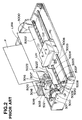
FIG. 1 is a cross-sectional view showing the configuration
of a first printing apparatus to which the present invention
can be applied, for example, a laser-beam printer
(hereinafter abbreviated as an LBP).
In FIG. 1, a main body 1500 of the LBP receives and
stores printing information (character codes and the like),
form information, macro commands and the like supplied from
an external apparatus, such as a host computer or the like
connected to the main body 1500, forms corresponding character
patterns, form patterns and the like in accordance with
the received information, and forms an image on recording
paper, serving as a recording medium. An operation panel
1501 is provided with switches for operations, an LED
(light-emitting diode) display unit and the like. A printer
control unit 1000 controls the entirety of the main body
1500, and analyzes character information and the like supplied
from the external apparatus. The printer control unit
1000 mainly converts character information into video signals
representing the corresponding character patterns, and
outputs the video signals to a laser driver 1502. The laser
driver 1502 includes circuitry for driving a semiconductor
laser 1503, and performs on-off switching of laser light
1504 emitted from the semiconductor laser 1503 in accordance
with the input video signals. The laser light 1504 is
deflected in rightward and leftward directions by a rotating
polygon mirror 1505 so as to scan and expose the surface of
an electrostatic drum 1506. An electrostatic latent image
corresponding to the character patterns is thereby formed on
the electrostatic drum 1506. The electrostatic latent image
is developed by a developing unit 1507 disposed around the
electrostatic drum 1506, and the developed image is transferred
onto recording paper. Cut sheets are used as the
recording paper. The cut-sheet recording paper is accommodated
within a paper cassette 1508 mounted on the main
body 1500. A sheet of the recording paper is fed within the
apparatus by a paper feeding roller 1509, a conveying roller
1510 and conveying rollers 1511, and is supplied to the
electrostatic drum 1506.
FIG. 2 is a diagram illustrating an external appearance
of a second printing apparatus to which the present invention
can be applied, for example, an ink-jet printing apparatus
(an IJRA).
In FIG. 2, a carriage HC engaging a screwed groove 5005
of a lead screw 5004 rotating via driving- force transmission
gears 5011 and 5009 meshed for movement with the
normal/reverse rotation of a driving motor 5013 includes a
pin (not shown), and is reciprocated in the directions of
arrows "a" and "b". An ink-jet cartridge IJC is mounted on
the carriage HC. A paper-pressing plate 5002 presses paper
against a platen 5000 over the moving direction of the carriage
HC. Photocouplers 5007 and 5008 function as homeposition
detection means for, for example, confirming the
presence of a lever 5006 of the carriage HC in the region
where the photocouplers 5007 and 5008 are present, and performing
switching of the direction of the rotation of the
motor 5013. A member 5016 supports a cap member 5022 for
capping the entire surface of a recording head IJH. A suction
pump 5015 sucks the inside of the cap member 5022, and
performs a recovering operation of the recording head by
suction via an opening 5023 of the cap member 5022. A cleaning
blade 5017 is movable in back-and-forth directions by
means of a member 5019. A supporting plate 5018 supports the
cleaning blade 5017 and the member 5019. A lever 5021 is
used to start suction for recovery, and moves in accordance
with the movement of a cam 5020 engaging the carriage HC.
The driving force of the driving motor 5013 is transmitted
by a known transmission means, such as a clutch or the like.
As for the above-described capping, cleaning, and
recovery by suction, the apparatus is configured so that
desired processing is performed at the corresponding position
by the operation of the lead screw 5004 when the carriage
HC reaches the home-position-side region. Any configuration
may be adopted provided that a desired operation
can be performed at a well-known timing.
Setting of various kinds of parameters of the second
printing apparatus shown in FIG. 2 are performed via an
operation panel (not shown) in which switches for operations,
an LED display and the like are disposed.
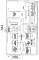
FIG. 3 is a block diagram showing the configuration of
a printing apparatus according to a first embodiment of the
present invention. Although an explanation will be provided
illustrating the laser-beam printer shown in FIG. 1, the
ink-jet printer shown in FIG. 2 or any other type of printing
apparatus may also be used.
In FIG. 3, an input/output control unit 1 receives
document information, image data, commands to call various
kinds of settings registered in the apparatus, and the like
input from an external apparatus 8, such as a host computer
or the like, or outputs setting information of the apparatus,
and the like to the external apparatus 8. Image
data and the like input from the external apparatus 8 via
the input/output control unit 1 are stored in a page memory
2 having a capacity for at least one page. The data to be
stored in the page memory 2 comprise image information,
document information, control codes for assigning emphasis
of characters, and the like. A character-generator unit 3
inputs character-code information when the document information
stored in the page memory 2 comprises the character-code
information, and outputs the corresponding pattern data
to a main control unit 4. A bit-map memory 9 develops bit
data and the like patterned by the character-generator unit
3.
The main control unit 4 controls the entirety of the
printing apparatus, and includes, for example, a CPU
(central processing unit ) 4-3, such as a microprocessor or
the like, a ROM (read-only memory) 4-1 for storing various
kinds of data, such as control programs (flowcharts shown in
FIGS. 4 and 6, and the like), and a RAM (random access
memory) 4-2 used as a work area, and the like.
A scanning buffer 5 includes buffers 5-1 and 5-2 for
storing image data used for one-line scanning of a laser
beam. The reason why the two buffers are provided is that
even if one of them outputs data to a printer-engine unit 7
via a serializer 6, the other buffer can store data for the
next line. When one buffer has completed the output of data
for one line, the other buffer starts to output data, and
data for the next line are transferred to the buffer which
has just completed the output of the data. Thereafter,
processing is alternately switched to the respective buffers.
Thus, high-speed processing is performed.
An operation panel 1501 includes a reading device comprising
an LED (light-emitting diode) display unit 11-1 and
an LCD (liquid-crystal display) display unit 11-2, and a
switch unit 11-3 for setting various kinds of parameters of
the printing apparatus, test printing and the like.
Various kinds of parameter settings, such as a
plurality of the kinds of paper cassettes, external interfaces,
page description languages, the kinds, pitches, and
point sizes of fonts, and the like, or combinations of the
settings set by operating the switch unit 11-3 can be
registered in a storage device or a setting storage unit 10.
The registration and calling or retrieving of a combination
of various kinds of settings can be performed by a setting
registration switch 11-4 and a setting calling switch 11-5,
respectively.
The operation of the present embodiment will now be explained
in detail with reference to the flowchart shown in
FIG. 4.
Various kinds of parameter settings set by operating
the operation switch unit 11-3 are displayed on the LED display
unit 11-1 or the LCD display unit 11-2. If the setting
registration switch 11-4 is depressed when the setting
operation has been completed (step S2), the contents of the
setting are written and registered in a memory device
provided within the setting storage unit 10 (step S3). By
repeating the above-described operation, it is possible to
register a plurality of set contents in the setting
registration unit 10.
On the other hand, if the setting calling switch 11-5
is depressed (step S4), the CPU 4-3 within the main control
unit 4 reads one of the set contents registered in the setting
storage unit 10, and switches the setting of the main
body of the apparatus (step S5), and displays the read set
contents on the LED display unit 11-1 or the LCD display
unit 11-2 (step S6).
If the setting calling switch 11-5 is depressed again,
the setting is switched to another registered setting. Thus,
the desired set contents can be selected.
A nonvolatile memory, such as a flash memory, an EEPROM
(electrically erasable/programmable read-only memory), an
NVRAM (nonvolatile random access memory) or the like, an
SRAM (static random access memory) backed up by a battery,
or the like, is used as the memory device within the setting
storage unit 10 so that the memory's contents are not lost
even if the power supply of the main body of the apparatus
is turned off.
Alternatively, when the power supply of the main body
of the apparatus is turned off, the contents set immediately
before the turning-off may be written in the memory device
within the setting storage unit 10 in accordance with a
program stored within the ROM 4-1. When the power supply is
turned on again, the CPU 4-3 may read the settings stored in
the setting storage unit 10 immediately before the power
supply has been turned off stored in the setting storage
unit 10, whereby the setting of the main body of the apparatus
is performed.
When printing data have been actually transmitted while
the connection between the printing apparatus and the external
apparatus 8 is in an on-line state, a printing operation
is performed in accordance with the set contents displayed
on the LCD unit 11-2 at that time (step S8).
Although in the above-described first embodiment, the
registration and calling of various kinds of setting or combinations
of the setting are executed by operating the setting
registration switch 11-4 and the setting calling switch
11-5 provided on the switch unit 11-3, respectively, the
present invention is not limited to such an operation. It is limited to the appended claims.
For example, the registration or calling of various
kinds of setting or combinations of the setting may be executed
by a command from the external apparatus 8.
In such a case, priority may be given to a command from
the external apparatus 8 in accordance with the flowchart
shown in FIG. 8.
An explanation will be provided of such an operation
with reference to the flowchart shown in FIG. 8. If a command
to call other set contents has been received from the
external apparatus 8 in step S81, the setting is switched to
the other set contents in accordance with the received command
in step S83, and the contents are displayed on the display
unit in step S84. This flowchart is inserted after step
S6 of the flowchart shown in FIG. 4, or step S67 of the
flowchart shown in FIG. 6 (to be described later), and the
process returns to step S1 or step S61 shown in FIG. 6 (to
be described later).
As explained above, according to the first embodiment,
by registering setting conditions which are frequently used
in the setting registration unit 10, a large number of key
operations required when various kinds of setting of the
printing apparatus are performed becomes unnecessary,
whereby a burden on the user caused by a complicated setting
method is reduced, and everybody can easily perform setting
of the printing apparatus.
Although in the present embodiment, an explanation has
been provided illustrating the laser-beam printer shown in
FIG. 1, the application of the present invention is not
limited to such a printer.
In addition, the present invention may, of course, be
applied to a case in which the aim of the invention is
achieved by supplying a system or an apparatus with a
program.
Next, an explanation will be provided of a second embodiment
of the present invention with reference to FIG. 5.
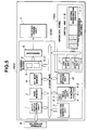
FIG. 5 is a diagram showing an example of the configuration
of a printing apparatus which can arbitrarily set
the functions of operation-panel switches. Since components
other than a switch unit 11-6 and programmable switches 12
are the same as those shown in FIG. 3, an explanation
thereof will be omitted.
Settings of various kinds of parameters, such as the
selection of a paper cassette, an external interface, a page
description language and the like, or combinations of the
settings set by operating the switch unit 11-6 or by the external
apparatus 8 are registered in the setting storage
unit 10 using a setting registration switch 11-7. At that
time, by setting to which programmable switch 12 each setting
corresponds, the user can arbitrarily determine the
correspondence between each of the registered contents and
each of the programmable switches.
The set contents registered in the setting storage unit
10 can be called by operating the programmable switch 12
corresponding to each of the contents.
The operation of the second embodiment will now be explained
in detail with reference to the flowchart shown in
FIG. 6.
Various kinds of setting information set by operating
the operation-switch unit 11-6 are dislayed on the LED display
unit 11-1 or the LCD display unit 11-2. When the setting
has been completed, the setting registration switch 11-7
is depressed (step S62). By depressing any of the programmable
switches 12, the set contents registered in step S62
can correspond to the depressed programmable switch 12 (step
S63). In step S64, the set contents are written and
registered in the memory device within the setting storage
unit 10 together with identifying information of the corresponding
programmable switch. By repeating the above-described
operation, a plurality of set contents can be
registered in the setting storage unit 10.
If it is determined that the setting registration
switch 11-7 has not been depressed in step S62, it is determined
whether or not any of the programmable switches 12
have been depressed (step S65). If the result of the determination
is affirmative, the CPU 4-3 within the main control
unit 4 reads the set contents corresponding to identifying
information of the depressed programmable switch (step S66)
and switches the setting of the main body of the apparatus,
and displays the read set contents on the LED display unit
11-1 or the LCD display unit 11-2 (step S67).
As described above, by depressing any of the programmable
switches 12, the setting is switched to another
registered setting, whereby the desired set contents can be
selected.
A nonvolatile memory, such as a flash memory, an EEPROM
(electrically erasable/programmable read-only memory), an
NVRAM (nonvolatile random access memory) or the like, an
SRAM (static random access memory) backed up by a battery,
or the like, is used as the memory device within the setting
storage unit 10 so that the memory's contents are not lost
even if the power supply of the main body of the apparatus
is turned off.
Alternatively, when the power supply of the main body
of the apparatus is turned off, the contents set immediately
before the turning-off may be written in the memory device
within the setting storage unit 10 in accordance with a
program stored within the ROM 4-1. When the power supply is
turned on again, the CPU 4-3 may read the settings stored in
the setting storage unit 10 immediately before the power
supply has been turned off, whereby the setting of the main
body of the apparatus is performed.
When printing data have been actually transmitted while
the connection between the printing apparatus and the external
apparatus 8 is in an on-line state, a printing operation
is performed in accordance with the set contents displayed
on the LCD unit 11-2 at that time (step S69).
Although in the above-described second embodiment, the
registration and calling of various kinds of setting or combinations
of the setting are executed by operating the setting
registration switch 11-7 and the programmable switches
12 provided on the switch unit 11-6, respectively, the
present invention is not limited to such an operation. It is limited to the appended claims.
For example, the registration or calling of various
kinds of setting or combinations of the setting may be executed
by a command from the external apparatus 8.
In such a case, priority may be given to a command from
the external apparatus 8 in accordance with the flowchart
shown in FIG. 8.
An explanation will be provided of such an operation
with reference to the flowchart shown in FIG. 8. If a command
to call other set contents has been received from the
external apparatus 8 in step S81, the setting is switched to
the other set contents in accordance with the received command
in step S83, and the contents are displayed on the display
unit in step S84. This flowchart is inserted after step
S67 of the flowchart shown in FIG. 6, and the process
returns to step S61 shown in FIG. 6.
As explained above, according to the second embodiment,
by registering setting conditions which are frequently used
in the setting registration unit 10, a large number of key
operations required when various kinds of settings of the
printing apparatus are performed becomes unnecessary,
whereby a burden on the user caused by a complicated setting
method is reduced, and everybody can easily perform setting
of the printing apparatus. In addition, when performing
various kinds of settings for the printing apparatus, by
registering the set contents in the setting storage unit 10
so that each of the set contents corresponds to one of the
programmable switches 12, a burden on the user caused by a
complicated setting method is reduced, and everybody can
easily set and call set contents of the printing apparatus.
Although in the present embodiment, an explanation has
been provided illustrating the laser-beam printer shown in
FIG. 1, the application of the present invention is not
limited to such a printer.
In addition, the present invention may, of course, be
applied to a case in which the object of the invention is
achieved by supplying a system or an apparatus with a
program.
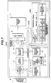
An LCD display unit 11-2 shown in FIG. 5 may be individually
provided for each of the programmable switches
12, as in the block diagram showing the configuration of a
printing apparatus according to a third embodiment of the
present invention shown in FIG. 7, so that when the user
switches the setting of the printing apparatus, the set contents
registered in each of the programmable switches 12 can
be always confirmed on each of the LCD display units 11-2.
The operation of the third embodiment is performed in accordance
with the flowcharts shown in FIGS. 6 and 8 in a
manner similar to that of the second embodiment.
The individual components shown in outline and designated
by blocks in the drawings are all well-known in the
image recording arts and their specific instruction and
operation are not critical to the operation or best mode of
carrying out the invention.
While the present invention has been described with
respect to what is currently considered to be the preferred
embodiments, it is to be understood that the invention is
not limited to the disclosed embodiments. To the contrary,
the invention is intended to cover various modifications and
equivalent arrangements included within the scope
of the appended claims. The scope of the following claims is
to be accorded to the broadest interpretation so as to encompass
all such modifications and equivalent structures and
functions.