EP0532210A2 - Liquid crystal display - Google Patents
Liquid crystal display Download PDFInfo
- Publication number
- EP0532210A2 EP0532210A2 EP92307860A EP92307860A EP0532210A2 EP 0532210 A2 EP0532210 A2 EP 0532210A2 EP 92307860 A EP92307860 A EP 92307860A EP 92307860 A EP92307860 A EP 92307860A EP 0532210 A2 EP0532210 A2 EP 0532210A2
- Authority
- EP
- European Patent Office
- Prior art keywords
- liquid crystal
- orientation
- substrates
- uniaxial orientation
- display device
- Prior art date
- Legal status (The legal status is an assumption and is not a legal conclusion. Google has not performed a legal analysis and makes no representation as to the accuracy of the status listed.)
- Granted
Links
Images


Classifications
-
- G—PHYSICS
- G02—OPTICS
- G02F—OPTICAL DEVICES OR ARRANGEMENTS FOR THE CONTROL OF LIGHT BY MODIFICATION OF THE OPTICAL PROPERTIES OF THE MEDIA OF THE ELEMENTS INVOLVED THEREIN; NON-LINEAR OPTICS; FREQUENCY-CHANGING OF LIGHT; OPTICAL LOGIC ELEMENTS; OPTICAL ANALOGUE/DIGITAL CONVERTERS
- G02F1/00—Devices or arrangements for the control of the intensity, colour, phase, polarisation or direction of light arriving from an independent light source, e.g. switching, gating or modulating; Non-linear optics
- G02F1/01—Devices or arrangements for the control of the intensity, colour, phase, polarisation or direction of light arriving from an independent light source, e.g. switching, gating or modulating; Non-linear optics for the control of the intensity, phase, polarisation or colour
- G02F1/13—Devices or arrangements for the control of the intensity, colour, phase, polarisation or direction of light arriving from an independent light source, e.g. switching, gating or modulating; Non-linear optics for the control of the intensity, phase, polarisation or colour based on liquid crystals, e.g. single liquid crystal display cells
- G02F1/137—Devices or arrangements for the control of the intensity, colour, phase, polarisation or direction of light arriving from an independent light source, e.g. switching, gating or modulating; Non-linear optics for the control of the intensity, phase, polarisation or colour based on liquid crystals, e.g. single liquid crystal display cells characterised by the electro-optical or magneto-optical effect, e.g. field-induced phase transition, orientation effect, guest-host interaction or dynamic scattering
- G02F1/139—Devices or arrangements for the control of the intensity, colour, phase, polarisation or direction of light arriving from an independent light source, e.g. switching, gating or modulating; Non-linear optics for the control of the intensity, phase, polarisation or colour based on liquid crystals, e.g. single liquid crystal display cells characterised by the electro-optical or magneto-optical effect, e.g. field-induced phase transition, orientation effect, guest-host interaction or dynamic scattering based on orientation effects in which the liquid crystal remains transparent
- G02F1/141—Devices or arrangements for the control of the intensity, colour, phase, polarisation or direction of light arriving from an independent light source, e.g. switching, gating or modulating; Non-linear optics for the control of the intensity, phase, polarisation or colour based on liquid crystals, e.g. single liquid crystal display cells characterised by the electro-optical or magneto-optical effect, e.g. field-induced phase transition, orientation effect, guest-host interaction or dynamic scattering based on orientation effects in which the liquid crystal remains transparent using ferroelectric liquid crystals
- G02F1/1416—Details of the smectic layer structure, e.g. bookshelf, chevron, C1 and C2
-
- G—PHYSICS
- G02—OPTICS
- G02F—OPTICAL DEVICES OR ARRANGEMENTS FOR THE CONTROL OF LIGHT BY MODIFICATION OF THE OPTICAL PROPERTIES OF THE MEDIA OF THE ELEMENTS INVOLVED THEREIN; NON-LINEAR OPTICS; FREQUENCY-CHANGING OF LIGHT; OPTICAL LOGIC ELEMENTS; OPTICAL ANALOGUE/DIGITAL CONVERTERS
- G02F1/00—Devices or arrangements for the control of the intensity, colour, phase, polarisation or direction of light arriving from an independent light source, e.g. switching, gating or modulating; Non-linear optics
- G02F1/01—Devices or arrangements for the control of the intensity, colour, phase, polarisation or direction of light arriving from an independent light source, e.g. switching, gating or modulating; Non-linear optics for the control of the intensity, phase, polarisation or colour
- G02F1/13—Devices or arrangements for the control of the intensity, colour, phase, polarisation or direction of light arriving from an independent light source, e.g. switching, gating or modulating; Non-linear optics for the control of the intensity, phase, polarisation or colour based on liquid crystals, e.g. single liquid crystal display cells
- G02F1/133—Constructional arrangements; Operation of liquid crystal cells; Circuit arrangements
- G02F1/1333—Constructional arrangements; Manufacturing methods
- G02F1/1337—Surface-induced orientation of the liquid crystal molecules, e.g. by alignment layers
- G02F1/133746—Surface-induced orientation of the liquid crystal molecules, e.g. by alignment layers for high pretilt angles, i.e. higher than 15 degrees
-
- G—PHYSICS
- G02—OPTICS
- G02F—OPTICAL DEVICES OR ARRANGEMENTS FOR THE CONTROL OF LIGHT BY MODIFICATION OF THE OPTICAL PROPERTIES OF THE MEDIA OF THE ELEMENTS INVOLVED THEREIN; NON-LINEAR OPTICS; FREQUENCY-CHANGING OF LIGHT; OPTICAL LOGIC ELEMENTS; OPTICAL ANALOGUE/DIGITAL CONVERTERS
- G02F1/00—Devices or arrangements for the control of the intensity, colour, phase, polarisation or direction of light arriving from an independent light source, e.g. switching, gating or modulating; Non-linear optics
- G02F1/01—Devices or arrangements for the control of the intensity, colour, phase, polarisation or direction of light arriving from an independent light source, e.g. switching, gating or modulating; Non-linear optics for the control of the intensity, phase, polarisation or colour
- G02F1/13—Devices or arrangements for the control of the intensity, colour, phase, polarisation or direction of light arriving from an independent light source, e.g. switching, gating or modulating; Non-linear optics for the control of the intensity, phase, polarisation or colour based on liquid crystals, e.g. single liquid crystal display cells
- G02F1/133—Constructional arrangements; Operation of liquid crystal cells; Circuit arrangements
- G02F1/1333—Constructional arrangements; Manufacturing methods
- G02F1/1337—Surface-induced orientation of the liquid crystal molecules, e.g. by alignment layers
- G02F1/13378—Surface-induced orientation of the liquid crystal molecules, e.g. by alignment layers by treatment of the surface, e.g. embossing, rubbing or light irradiation
- G02F1/133784—Surface-induced orientation of the liquid crystal molecules, e.g. by alignment layers by treatment of the surface, e.g. embossing, rubbing or light irradiation by rubbing
Definitions
- the present invention relates to a liquid crystal display device and more particularly, to a liquid crystal display device using a ferroelectric liquid crystal.
- a conventional liquid crystal display device using a nematic liquid crystal comprises a twisted nematic (TN) type liquid crystal display device and a supertwisted birefringence effect (SBE) type liquid crystal display device.
- TN twisted nematic
- SBE supertwisted birefringence effect
- the twisted nematic type liquid crystal display device In the twisted nematic type liquid crystal display device, however, as a driving method becomes multiplex, a driving margin becomes narrow, so that sufficient contrast can not be obtained. In the supertwisted birefringence effect type liquid crystal display using a large twist angle, which is an improved display device of the twisted nematic type liquid crystal display device, when it is used in large-capacity display device, the contrast is lowered or response speed is decreased.
- This liquid crystal display device is different from the above liquid crystal device using an electric field effect in which dielectric anisotropy of a liquid crystal molecule is used and has a structure employing rotating force for matching a polarity of a spontaneous polarization of the ferroelectric liquid crystal with a polarity of the electric field.
- This liquid crystal device has a bistable characteristic, a memory characteristic, and high-speed response characteristic.
- the ferroelectric liquid crystal when the ferroelectric liquid crystal is injected into a cell having a thin gap, a spiral structure of the ferroelectric liquid crystal is broken by an influence of an interface of the substrate, and then there exist together a region where the liquid crystal molecule is inclined from the normal line of the smectic layer by an angle of ⁇ and a region where the liquid crystal molecule is inclined in the opposite direction by - ⁇ , so that bistable property is provided.
- the directions of the liquid crystal molecule and its spontaneous polarization can be uniform by applying a voltage to the ferroelectric liquid crystal in the cell. Therefore, by switching the polarity of the voltage to be applied, the orientation of the liquid crystal molecule can be switched from a certain constant state to another constant state.
- the ferroelectric liquid crystal display device oriented by rubbing has the twisted orientation because regulating force at the interface strongly acts thereon. In such orientation, it is found that a difference in optical molecular axis in switching between two states does not generally effectively appear and high contrast characteristic is not obtained.
- a layer structure model proposed by Clark et al For example, there is one example in which an SiO oblique deposition method is used, and then the layer is prevented from being doglegged by applying a relatively high pretilt to the substrate interface to attain an oblique layer structure.
- a ferroelectric liquid crystal display device includes a pair of substrates on which an electrode is selectively formed on the surface, then an insulating film and an orientation film are formed thereon and uniaxial orientation processing is performed and which are arranged so that directions of their uniaxial orientation processing may be almost parallel to each other; a liquid crystal panel which is formed by injecting a liquid crystal having a chiral smectic C phase between the substrates; driving means for switching an optical axis of the liquid crystal by selectively applying a voltage to the electrode; and means for optically identifying the switching of the optical axis, in which the liquid crystal shows a chevron structure as a layer structure at the chiral smectic C phase in which a layer structure is doglegged, and an orientation region generated from interaction in the uniaxial orientation processing direction and the layer structure is an inside region surrounded by a lightning defect generated in the uniaxial orientation direction and a hair pin defect generated behind the lightning defect or an outside region surrounded by the hair pin defect generated in
- the uniaxial orientation processing is performed on the orientation film by the rubbing method.
- a liquid crystal of the present invention is a liquid crystal having a chiral smectic C phase like as cyanophenyl cyclohexane type, cyanobiphenyl type, fluoride type, tolane type and so on.
- the driving method of the present invention can be employed such a conventional method that a signal is applied to the scanning electrodes and signal electrodes connected to pixels .
- a liquid crystal molecule is inverted not only in the vicinity of the doglegged region in the chevron structure generated almost in the center of the pair of substrates but also in the vicinity of the substrates. Therefore, although the orientation of the liquid crystal molecule is a little different from each other because of the doglegged structure in the vicinity of the substrates, the liquid crystal molecule is almost uniformly oriented between the substrate and the vicinity of the interface and then it is uniform from one substrate to the border and from the border to the other substrate. As a result, the liquid crystal molecule shows the orientation which is not almost twisted.
- the liquid crystal is not almost twisted, it is possible to prevent leakage of light when the light is shielded by using with means for optically identifying the switching of the optical axis such as the polariser, and thus the contrast characteristic can be improved.
- the doglegged direction in the chevron structure in the present invention is the direction generated inside the region surrounded by the lightning defect generated in the uniaxial orientation processing direction and the hair pin defect generated behind the lightning defect or outside the region surrounded by the hair pin defect generated in the uniaxial orientation processing direction and the lightning defect generated behind the hair pin defect. Therefore, when the optical axis of the liquid crystal is switched by the driving means in the present invention, the difference between the optical molecular axes of two states, that is, the memory angle is large.
- the doglegged direction of the layer can be further easily implemented by a simple rubbing method.
- the layer structure of the chiral smectic C phase is generally a doglegged structure.
- the reason for the structure is that the molecule in the vicinity of the border of the substrates is not likely to move, while the space between layers in the liquid crystal phase (generally a smectic A phase) at a temperature higher than that of the chiral smectic C phase is reduced because the liquid crystal molecule is inclined when changed to the chiral smectic C phase. It is thought that the liquid crystal molecule in the middle phase at a high temperature is extended so as to keep the space between the molecules, while the space between molecules of the liquid crystal molecule at the interfaces remained.
- the above doglegged structure is employed, which will be described in detail hereinafter.
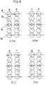
- orientation processing directions in the upper and lower substrates are the same, there are two different orientations, which depends on whether the doglegged direction is the same as the orientation processing direction or it is opposite, which is shown in Fig. 5.
- a cone shape shown in Fig. 5 is a raceway track on which the liquid crystal molecule can move on switching, which is inclined from the layer normal line 25 by the tilt angle 26 of the liquid crystal.
- An arrow 19 shows the rubbing direction.
- This relation is discussed in Japanese Unexamined Patent No. 158415/1989, in which a layer structure 23 shown in Fig. 5 where the rubbing direction is opposite to the doglegged direction in the layer is defined as chevron 1 (C1 orientation) and a layer structure 24 shown in Fig. 5 where the rubbing direction is the same as the doglegged direction in the layer is defined as chevron 2 (C2 orientation).
- chevron 1 C1 orientation
- a layer structure 24 shown in Fig. 5 where the rubbing direction is the same as the doglegged direction in the layer is defined as chevron 2 (C2 orientation).
- C1 orientation chevron 1
- C2 orientation chevron 2
- the C1 orientation and C2 orientation show almost the equivalent orientation when there is no pretilt of the liquid crystal molecule at the interface of the substrates.
- a pretilt 22 of the liquid crystal molecule is generated in the direction shown in Fig. 6. If the pretilt is increased, the difference in the orientation of the liquid crystal molecule between the C1 and C2 becomes obvious, which is shown in Fig. 9.
- a, b, c and d designate molecules of the C1 and C2 orientations when the molecules are not likely to move at the interface of the substrates, which are shown by a display method using the C director. Since the liquid crystal molecules are twisted in the upper and lower substrates, in this case, the C1 orientation and C2 orientation are defined as C1T (C1 twist) orientation and C2T (C2 twist) orientation, respectively.
- the switching when the electric field is applied occurs between a and b and between c and d. In this case, the switching of the memory state occurs only at a joint part 14 of the chevron structure.
- an n director 20 is considerably twisted in the C1T orientation of a and b in Fig. 9, while it is twisted a little in the C2T orientation of c and d in Fig. 9.
- the polarizing plates are arranged so as to cross at right angles at the upper and lower cells and the cell is rotated therein, there is not quenching angle in the C1T orientation and there is a quenching angle in the C2T orientation.
- Japanese Unexamined Patent No. 158415 Japanese Unexamined Patent No. 158415
- e, f, g, and h shows molecule of the C1 and C2 orientations in the memory state when the interface invention is generated.
- the C1 orientation and C2 orientation are defined as C1U (C1 uniform) orientation and C2U (C2 uniform) orientation, respectively.
- the switching when the electric field is applied occurs between e and f, and between g and h.
- the contrast characteristic has the following relation.
- the C1U orientation is employed in the liquid crystal display device in view of the fact described above. How to distinguish these orientations will be described hereinafter in view of the fact described above.
- the doglegged direction of the layer can be estimated from the configuration of the zigzag defect generated from a damage in the cell or the spacer.
- There are two kinds of configurations in the defect such as the lightning defect and the hair pin defect. Normally, these two defects are connected and it is known that the doglegged direction of the layer at a region surrounded by the defects is different from that of the outside thereof (referring to Fig. 2). Therefore, the rubbing direction and the doglegged direction of the layer can be estimated.
- the rubbing direction is the direction of the pretilt of the molecule, which shown in Fig. 6.
- the C1U orientation in which high contrast can be obtained is employed in the liquid crystal display device in view of the fact described above.
- the angle of inclination ⁇ of the layer of the chevron structure was measured using various liquid crystals shown in table 1 by X-ray diffraction method, which is shown in Fig. 7.
- the liquid crystals CS-1014 and CS-1022 are made by Chisso Petrochemical Co., Ltd and the liquid crystals ZLI-3654 and ZLI-3489 are made by Merck & Co.
- the liquid crystal FELIX-002 is made by Hoechst AG
- Mixture A is a liquid crystal as follows. and x in the figure are data when a polyimide material (PSI-A-2001 made by Chisso Petrochemical Co., Ltd.) and polyvinyl alcohol (PVA) are used as the orientation film.
- PSI-A-2001 made by Chisso Petrochemical Co., Ltd.
- PVA polyvinyl alcohol
- the angle of inclination ⁇ is a little smaller than the tilt angle ⁇ .
- Two orientation states shown in Fig. 5 are drawn from the above relation. Then, it is found that there is a difference in stability of generation of the C1 orientation and C2 orientation, depending on the relation of the angle of inclination ⁇ 28 of the layer and the tilt angle ⁇ 26.
- the another means described above is technique implementing that an interface pretilt ⁇ p (angle formed between the substrate and the liquid crystal molecule) >> the tilt angle ⁇ (an angle when a cone angle of the liquid crystal molecule in the C1U orientation is 2 ⁇ ) disclosed in Japanese Unexamined Patent No. 7879/1991 or technique implementing the interface pretilt of 8 to 35 ° disclosed in Japanese Unexamined Patent No. 32395/1991.
- Fig. 8 is a graph showing the relation between ⁇ (28) > ⁇ (26) and ⁇ (26) for more detail examination, where ⁇ / ⁇ is an absolute value.
- ⁇ / ⁇ is an absolute value.
- a liquid crystal display device according to the present invention will be described in reference to an embodiment of the present invention.
- Fig. 1 is a sectional view showing the liquid crystal display device of the present invention.
- a plurality of transparent electrodes 2a having a thickness of 300 to 5000 ⁇ , preferably 1000 to 3000 ⁇ , which are arranged in the form of stripes so as to be parallel to each other, are formed on a glass substrate 1a.
- an electrode protective film 3a formed of SiO2 having a thickness 300 to 5000 ⁇ , preferably 1000 to 2000 ⁇ is formed thereon by sputtering and then a PSI-A-2001 (polyimide) orientation film 4a made by Chisso Petrochemical Co., Ltd. is formed thereon with a thickness of 400 ⁇ by spin coating.
- the uniaxial orientation processing is performed using rayon cloth by a rubbing method.
- a substrate 9 is formed.
- a plurality of transparent electrodes 2b are arranged in the form of stripes so as to be parallel to each other on another glass substrate 1b in the same manner and then an orientation film 4b is formed through an electrode protective film 3b under the same condition. Thereafter, the uniaxial orientation processing is performed by the rubbing method. Thus, another substrate 10 is formed.
- the substrates 10 and 9 are put together at a distance of 1.5 ⁇ m through a silica spacer 5 with a sealing material 6 formed of epoxy resin so that the orientation films 4a and 4b may be opposite to each other, the transparent electrodes 2a and 2b may cross at right angles, and the rubbing directions coincide with each other.
- a liquid crystal 7 showing a chiral smectic C phase is injected between the substrates 9 and 10 from an inlet by a vacuum injection method while the liquid crystal is heated, and then the inlet is shielded by an acrylic resin of a UV curing type.
- a liquid crystal cell 11 is made.
- polarizing plates 12a and 12b whose polarizing axes cross at right angles are arranged on the upper and lower side of the cell and one polarizing axis of the polarizing plate is made to coincide with either one of optical axes of the liquid crystal of the cell 11.
- the liquid crystal display device is made.
- the state of orientation is observed through experiments in the liquid crystal display device to which various liquid crystals shown in table 1 are injected.
- the C1U orientation is seen from a transition point (T AC ) from the smectic A phase to the smectic C phase, to the vicinity of the room temperature (25°C), which is confirmed by the above described method.
- the C1U orientation and C2U orientation exist together from T AC to the vicinity of the room temperature.
- the C1U orientation and C2 orientation exist together from T AC to the vicinity of the room temperature.
- Table 2 Liquid Crystal Material( ⁇ / ⁇ ) Orientation Film Orientation CS-1014 (0.918) PSI-A-2001 C1U PVA C1T Mixture A (0.982) PSI-A-2001 C1U PVA C1T CS-1022 (0.936) PSI-A-2001 C1U PVA C1T ZLI-3654 (0.845) PSI-A-2001 C1U,C2 PVA C1T,C2 ZLI-3489 (0.872) PSI-A-2001 C1U,C2 PVA C1T,C2 FELIX-002 (0.892) PSI-A-2001 C1U,C2 PVA C1T,C2
- the C2 orientation can be prevented from being generated and the C1 orientation can be stably obtained. Furthermore, the CIU orientation can be stably obtained by another well-known means and further high contrast characteristic (40 or more) can be attained.
Abstract
Description
- The present invention relates to a liquid crystal display device and more particularly, to a liquid crystal display device using a ferroelectric liquid crystal.
- A conventional liquid crystal display device using a nematic liquid crystal comprises a twisted nematic (TN) type liquid crystal display device and a supertwisted birefringence effect (SBE) type liquid crystal display device.
- In the twisted nematic type liquid crystal display device, however, as a driving method becomes multiplex, a driving margin becomes narrow, so that sufficient contrast can not be obtained. In the supertwisted birefringence effect type liquid crystal display using a large twist angle, which is an improved display device of the twisted nematic type liquid crystal display device, when it is used in large-capacity display device, the contrast is lowered or response speed is decreased.
- Then, in order to improve the liquid crystal display device using the nematic liquid crystal, there was proposed a liquid crystal display device using a chiral smectic C liquid crystal, that is, a ferroelectric liquid crystal by N. A. Clark and Lagerwall in 1980 (Japanese Unexamined Patent No. 107216/1981, and U.S.Patent No. 4367924).
- This liquid crystal display device is different from the above liquid crystal device using an electric field effect in which dielectric anisotropy of a liquid crystal molecule is used and has a structure employing rotating force for matching a polarity of a spontaneous polarization of the ferroelectric liquid crystal with a polarity of the electric field. This liquid crystal device has a bistable characteristic, a memory characteristic, and high-speed response characteristic. More specifically, when the ferroelectric liquid crystal is injected into a cell having a thin gap, a spiral structure of the ferroelectric liquid crystal is broken by an influence of an interface of the substrate, and then there exist together a region where the liquid crystal molecule is inclined from the normal line of the smectic layer by an angle of Θ and a region where the liquid crystal molecule is inclined in the opposite direction by -Θ, so that bistable property is provided. The directions of the liquid crystal molecule and its spontaneous polarization can be uniform by applying a voltage to the ferroelectric liquid crystal in the cell. Therefore, by switching the polarity of the voltage to be applied, the orientation of the liquid crystal molecule can be switched from a certain constant state to another constant state.
- Since birefringent light in the ferroelectric liquid crystal in the cell is changed by the switching operation, transmitted light can be controlled by sandwiching the cell between two polarizers. In addition, even if the application of the voltage is stopped, the orientation of the liquid crystal molecule is kept at a state before application of the voltage is stopped, so that the memory effect can be also obtained. A time required for driving !he switching operation has high-speed response characteristic, that is, below 1/1000 of the twisted menatic type liquid crystal display device because the spontaneous polarization of the liquid crystal and the electric field directly affect it, enabling high-speed display. Thus, by using the memory effect or the high-speed response characteristic of the ferroelectric liquid crystal, there has been implemented a liquid crystal display device of high resolution in which there are many scanning lines using a multiplex driving method.
- However, there are many problems in the liquid crystal display device proposed by Clark and Lagerwall. That is, it is thought that in a first model, a layer structure of the smectic C phase has a structure perpendicular to a substrate, called bookshelf type shown in Fig. 3.
- However, in a case where a cell is made by using a conventional orientation method by rubbing or the like, it has been found that switching phenomenon and an optical characteristic is considerably different from that expected, and its switching operation is completely different from that of the proposed model.
- As one reason for the above, it was analyzed using a small angle scattering method of X-ray that the layer structure is doglegged, called a chevron structure shown in Fig. 4. [ Phys. Rev. Lett., 59, pp.2658 (1987) by Rieker, T.P., Clark, N.A, ]
- In addition, it is also different from the first model in that the direction of the spontaneous polarization and the liquid crystal molecule have uniform orientation and also the molecule has a twisted orientation between upper and lower substrates. [Glogarova, M. and Pavel, J., J.Phys. (France), 45, pp.143 (1984) ]
- Especially, the ferroelectric liquid crystal display device oriented by rubbing has the twisted orientation because regulating force at the interface strongly acts thereon. In such orientation, it is found that a difference in optical molecular axis in switching between two states does not generally effectively appear and high contrast characteristic is not obtained. In order to solve the above problems, there are proposed several methods to attain a layer structure model proposed by Clark et al. For example, there is one example in which an SiO oblique deposition method is used, and then the layer is prevented from being doglegged by applying a relatively high pretilt to the substrate interface to attain an oblique layer structure.
- In addition, there is another method in which the layer structure is changed to the bookshelf structure by applying an alternating electric field of a high voltage to the cell having the doglegged structure [the twelfth Liquid Crystal Meeting (Nagoya) by Sato et al., 1F16 (1986)]. It has been reported that high contrast can be provided by either method.
- However, in the above oblique deposition method, it is difficult to make the deposition angle uniform and there is a big problem in productivity because of vacuum processing. In addition, in the method which applies the electric field, it is difficult to uniformly change the layer structure because it gradually changes to the chevron structure with the lapse of time, so that it has not been put to practical use.
- According to the present invention, a ferroelectric liquid crystal display device includes a pair of substrates on which an electrode is selectively formed on the surface, then an insulating film and an orientation film are formed thereon and uniaxial orientation processing is performed and which are arranged so that directions of their uniaxial orientation processing may be almost parallel to each other; a liquid crystal panel which is formed by injecting a liquid crystal having a chiral smectic C phase between the substrates; driving means for switching an optical axis of the liquid crystal by selectively applying a voltage to the electrode; and means for optically identifying the switching of the optical axis, in which the liquid crystal shows a chevron structure as a layer structure at the chiral smectic C phase in which a layer structure is doglegged, and an orientation region generated from interaction in the uniaxial orientation processing direction and the layer structure is an inside region surrounded by a lightning defect generated in the uniaxial orientation direction and a hair pin defect generated behind the lightning defect or an outside region surrounded by the hair pin defect generated in the uniaxial orientation direction and a lightning defect generated behind the hair pin defect, the liquid crystal can invert to switch an orientation axis near the substrates, and a ratio of an angle δ of inclination of a layer of the liquid crystal to the substrate, to a tilt angle Θ is made to be from 0.9 to 1.
- In addition, according to the present invention, the uniaxial orientation processing is performed on the orientation film by the rubbing method.
-
- Fig. 1 is a schematic sectional view showing a liquid crystal display device according to an embodiment of the present invention;
- Fig. 2 is a schematic view showing a layer structure of a chiral smectic C phase according to the embodiment of the present invention;
- Fig. 3 is a schematic view showing a layer structure of a chiral smectic C phase in a conventional example;
- Fig. 4 is a schematic view showing a layer structure of a chiral smectic C phase;
- Fig. 5 is a schematic view showing C1 orientation and C2 orientation according to the embodiment of the present invention;
- Fig. 6 is a view showing a rubbing processing according to the embodiment of the present invention;
- Fig. 7 is a graph showing a relation between an angle of inclination of a layer and a tilt angle of a molecule;
- Fig. 8 is a graph showing a ratio of the angle of inclination of the layer to the tilt angle of the molecule according to the embodiment of the present invention;
- Fig. 9 is a view showing a C director of the C1 orientation and C2 orientation according to the embodiment of the present invention; and
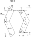
- Fig. 10 is a schematic view of the C1 orientation and C2 orientation when δ = Θ.
- It is an object of the present invention to provide a liquid crystal display device having high contrast in a chevron structure.
- A liquid crystal of the present invention is a liquid crystal having a chiral smectic C phase like as cyanophenyl cyclohexane type, cyanobiphenyl type, fluoride type, tolane type and so on.
- The driving method of the present invention can be employed such a conventional method that a signal is applied to the scanning electrodes and signal electrodes connected to pixels .
- According to the present invention, when an optical axis of the liquid crystal is switched by the driving means, a liquid crystal molecule is inverted not only in the vicinity of the doglegged region in the chevron structure generated almost in the center of the pair of substrates but also in the vicinity of the substrates. Therefore, although the orientation of the liquid crystal molecule is a little different from each other because of the doglegged structure in the vicinity of the substrates, the liquid crystal molecule is almost uniformly oriented between the substrate and the vicinity of the interface and then it is uniform from one substrate to the border and from the border to the other substrate. As a result, the liquid crystal molecule shows the orientation which is not almost twisted.
- Thus, since the liquid crystal is not almost twisted, it is possible to prevent leakage of light when the light is shielded by using with means for optically identifying the switching of the optical axis such as the polariser, and thus the contrast characteristic can be improved.
- The doglegged direction in the chevron structure in the present invention is the direction generated inside the region surrounded by the lightning defect generated in the uniaxial orientation processing direction and the hair pin defect generated behind the lightning defect or outside the region surrounded by the hair pin defect generated in the uniaxial orientation processing direction and the lightning defect generated behind the hair pin defect. Therefore, when the optical axis of the liquid crystal is switched by the driving means in the present invention, the difference between the optical molecular axes of two states, that is, the memory angle is large. Therefore, when the optical axis of the liquid crystal is switched, since the difference in amount of transmitted light between the state transmitting the light and the state not transmitting light can be large when using with the means, for example a polarizer, for optically identifying the switching of the optical axis, high contrast is obtained.
- According to the present invention, when a ratio δ/Θ of the angle δ of the smectic layer to the substrate to the tilt angle Θ is from 0.9 to 1, the doglegged direction of the layer can be further easily implemented by a simple rubbing method.
- The present invention will be described in detail in reference to embodiments shown in the drawings. However, the present invention is not limited to the following embodiments.
- It is known that the layer structure of the chiral smectic C phase is generally a doglegged structure. The reason for the structure is that the molecule in the vicinity of the border of the substrates is not likely to move, while the space between layers in the liquid crystal phase (generally a smectic A phase) at a temperature higher than that of the chiral smectic C phase is reduced because the liquid crystal molecule is inclined when changed to the chiral smectic C phase. It is thought that the liquid crystal molecule in the middle phase at a high temperature is extended so as to keep the space between the molecules, while the space between molecules of the liquid crystal molecule at the interfaces remained. Therefore, the space between layers of the liquid crystal molecule has be to reduced as a whole, so that the layer is doglegged. However, there are two
doglegged directions - As shown in Fig. 2, there are generated two kinds of defects in the zigzag defect at the doglegged part in the layer. Judging from their configurations, one of them is called
lightning defect 15 and the other is calledhair pin defect 16. The doglegged directions can be estimated from their configurations. [Jpn. J. Appl. Phys., 28, pp.50 (1988)] - According to the present invention, the above doglegged structure is employed, which will be described in detail hereinafter. When the orientation processing directions in the upper and lower substrates are the same, there are two different orientations, which depends on whether the doglegged direction is the same as the orientation processing direction or it is opposite, which is shown in Fig. 5.
- A cone shape shown in Fig. 5 is a raceway track on which the liquid crystal molecule can move on switching, which is inclined from the layer
normal line 25 by thetilt angle 26 of the liquid crystal. Anarrow 19 shows the rubbing direction. This relation is discussed in Japanese Unexamined Patent No. 158415/1989, in which alayer structure 23 shown in Fig. 5 where the rubbing direction is opposite to the doglegged direction in the layer is defined as chevron 1 (C1 orientation) and alayer structure 24 shown in Fig. 5 where the rubbing direction is the same as the doglegged direction in the layer is defined as chevron 2 (C2 orientation). The same definition is used also in this specification. - The C1 orientation and C2 orientation show almost the equivalent orientation when there is no pretilt of the liquid crystal molecule at the interface of the substrates. However, when the uniaxial orientation processing such as the rubbing processing is performed, a
pretilt 22 of the liquid crystal molecule is generated in the direction shown in Fig. 6. If the pretilt is increased, the difference in the orientation of the liquid crystal molecule between the C1 and C2 becomes obvious, which is shown in Fig. 9. - Referring to Fig. 9, a, b, c and d designate molecules of the C1 and C2 orientations when the molecules are not likely to move at the interface of the substrates, which are shown by a display method using the C director. Since the liquid crystal molecules are twisted in the upper and lower substrates, in this case, the C1 orientation and C2 orientation are defined as C1T (C1 twist) orientation and C2T (C2 twist) orientation, respectively. The switching when the electric field is applied occurs between a and b and between c and d. In this case, the switching of the memory state occurs only at a
joint part 14 of the chevron structure. - Referring to Fig. 5, in reference to arrangement of the molecules at the interface between the upper and lower substrates, an
n director 20 is considerably twisted in the C1T orientation of a and b in Fig. 9, while it is twisted a little in the C2T orientation of c and d in Fig. 9. When the polarizing plates are arranged so as to cross at right angles at the upper and lower cells and the cell is rotated therein, there is not quenching angle in the C1T orientation and there is a quenching angle in the C2T orientation. As a result, it is found that the better contrast characteristic can be obtained in the C2T orientation than the C1T orientation. (Japanese Unexamined Patent No. 158415) - However, when the molecules in the vicinity of the interface is made easily movable and the interface invention of the molecule is generated, the conditions are different. In Fig. 9, e, f, g, and h shows molecule of the C1 and C2 orientations in the memory state when the interface invention is generated.
- Since the twist of the liquid crystal molecules is untwisted at the upper and lower substrates, the molecules are uniformly arranged. In this case, the C1 orientation and C2 orientation are defined as C1U (C1 uniform) orientation and C2U (C2 uniform) orientation, respectively. The switching when the electric field is applied occurs between e and f, and between g and h.
- In this case, in the C1U orientation, there is no twist of the molecules at the upper and lower substrates in both two memory states and an optical axis angle (memory angle ϑ) between two memory states is increased. Therefore, quenching is possible in orthogonal nicol and also a large change in intensity of transmitted light can be obtained by putting a cell at a quenching position and applying a voltage thereto, because the optical angle is largely moved when the optical axis is switched to the other memory state.
- However, in the C2U orientation, even if the invention of the molecule in the vicinity of the interface occurs, as can seen from Fig. 9, the optical axis can not be large changed between the first memory state and the second memory state. Therefore, higher contrast can be obtained in the C1U orientation.
- Thus, the contrast characteristic has the following relation.
- Large contrast C1U > C2U ≧ C2T > C1T Small contrast
- According to the present invention, the C1U orientation is employed in the liquid crystal display device in view of the fact described above. How to distinguish these orientations will be described hereinafter in view of the fact described above.
- First, how to distinguish C1 from C2 will be described. The doglegged direction of the layer can be estimated from the configuration of the zigzag defect generated from a damage in the cell or the spacer. There are two kinds of configurations in the defect such as the lightning defect and the hair pin defect. Normally, these two defects are connected and it is known that the doglegged direction of the layer at a region surrounded by the defects is different from that of the outside thereof (referring to Fig. 2). Therefore, the rubbing direction and the doglegged direction of the layer can be estimated. In addition, the rubbing direction is the direction of the pretilt of the molecule, which shown in Fig. 6.
- Next, it will be described how to distinguish the twisted orientation from the uniform orientation.
- 1. When a chopping wave of low frequency is applied to the cell, an inversion domain is observed by a microscope. At that time, the domain inversion (called a domain of a boat form) because of movement of internal disclination generated at the joint (the doglegged part) of the chevron is generated regardless of the twisted orientation or the uniform orientation. Therefore, when one or more domain inversions except for that inversion are observed, it is determined that the inversion is the one at the interface and then it is through the uniform state at the time of switching.
- 2. When a ratio of the optical axis angle between two stable states (no voltage is applied) at the time of memory to the moving angle of the optical axis found by applying a sufficient electric field (approximately ±10V) to the cell is 40% or more, it is the uniform orientation. In the twisted orientation, the value is only approximately 30% level.
- Therefore, according to the present invention, the C1U orientation in which high contrast can be obtained is employed in the liquid crystal display device in view of the fact described above.
- The angle of inclination δ of the layer of the chevron structure was measured using various liquid crystals shown in table 1 by X-ray diffraction method, which is shown in Fig. 7.

where the liquid crystals CS-1014 and CS-1022 are made by Chisso Petrochemical Co., Ltd and the liquid crystals ZLI-3654 and ZLI-3489 are made by Merck & Co., the liquid crystal FELIX-002 is made by Hoechst AG, and Mixture A is a liquid crystal as follows.


and x in the figure are data when a polyimide material (PSI-A-2001 made by Chisso Petrochemical Co., Ltd.) and polyvinyl alcohol (PVA) are used as the orientation film. It is found by Rieker et al. that the pretilt angle of both orientation films of the PSI-A-2001 is approximately 15° and that of the PVA is approximately 0.5°, which is considerably different, but the angle of inclination δ of the layer does not depend on the orientation film. [T.P. Rieker, N.A.Clark et al. Phys. Rev. lett., 59. pp.2658 (1987). However, a method for measuring the pretilt angle of the ferroelectric liquid crystal has not been established yet, so that the pretilt angle in this embodiment is a value measured for the nematic liquid crystal. The dotted lines in the figure show the relation that δ = Θ ( tilt angle). As can be seen from the figure, the angle of inclination δ is a little smaller than the tilt angle Θ. Two orientation states shown in Fig. 5 are drawn from the above relation. Then, it is found that there is a difference in stability of generation of the C1 orientation and C2 orientation, depending on the relation of the angle of inclination δ 28 of the layer and thetilt angle Θ 26. - When δ > Θ, the layer is not stable in view of energy and actually such layer has not been observed. When δ << Θ, the C1 orientation and C2 orientation both exist in a stable manner and even if the pretilt at the interface is large to a certain degree, the C2 orientation exists. However, when δ = Θ, the C2 orientation exists only under the condition that there is no pretilt at the interface, which is shown in Fig. 10.
- As described above, when the uniaxial processing is performed, the pretilt is generated. Therefore, if a material which satisfies the condition that δ = Θ is selected, the C1 orientation can be stably provided, preventing generation of the C2 orientation. Thus, the C1 orientation can be stably obtained by another well-known means and further high contrast characteristic can be obtained. The another means described above is technique implementing that an interface pretilt Θp (angle formed between the substrate and the liquid crystal molecule) >> the tilt angle Θ (an angle when a cone angle of the liquid crystal molecule in the C1U orientation is 2 Θ) disclosed in Japanese Unexamined Patent No. 7879/1991 or technique implementing the interface pretilt of 8 to 35 ° disclosed in Japanese Unexamined Patent No. 32395/1991.
- Fig. 8 is a graph showing the relation between δ(28) > Θ(26) and Θ(26) for more detail examination, where δ / Θ is an absolute value. Actually, in a material having δ / Θ of from 0.9 to 1, the C2 orientation does not exist and the C1 orientation can be stably obtained like in the above condition that δ = Θ.
- A liquid crystal display device according to the present invention will be described in reference to an embodiment of the present invention.
- Fig. 1 is a sectional view showing the liquid crystal display device of the present invention. Referring to Fig. 1, a plurality of
transparent electrodes 2a having a thickness of 300 to 5000Å, preferably 1000 to 3000Å, which are arranged in the form of stripes so as to be parallel to each other, are formed on a glass substrate 1a. Then, an electrodeprotective film 3a formed of SiO₂ having a thickness 300 to 5000Å, preferably 1000 to 2000Å is formed thereon by sputtering and then a PSI-A-2001 (polyimide)orientation film 4a made by Chisso Petrochemical Co., Ltd. is formed thereon with a thickness of 400Å by spin coating. Thereafter, the uniaxial orientation processing is performed using rayon cloth by a rubbing method. Thus, asubstrate 9 is formed. - Meanwhile, a plurality of transparent electrodes 2b are arranged in the form of stripes so as to be parallel to each other on another
glass substrate 1b in the same manner and then anorientation film 4b is formed through an electrodeprotective film 3b under the same condition. Thereafter, the uniaxial orientation processing is performed by the rubbing method. Thus, anothersubstrate 10 is formed. - Then, the
substrates silica spacer 5 with a sealingmaterial 6 formed of epoxy resin so that theorientation films transparent electrodes 2a and 2b may cross at right angles, and the rubbing directions coincide with each other. - Then, a
liquid crystal 7 showing a chiral smectic C phase is injected between thesubstrates liquid crystal cell 11 is made. - Then,
polarizing plates cell 11. Thus, the liquid crystal display device is made. - The state of orientation is observed through experiments in the liquid crystal display device to which various liquid crystals shown in table 1 are injected.
- In the device to which CS-1014 and CS-1022 mixture A is injected, the C1U orientation is seen from a transition point (TAC) from the smectic A phase to the smectic C phase, to the vicinity of the room temperature (25°C), which is confirmed by the above described method.
- In the device to which ZLI-3654, ZLI-3489, and FELIX-002 are injected, the C1U orientation and C2U orientation exist together from TAC to the vicinity of the room temperature.
- In a liquid crystal display device having the orientation film of PVA of the above structure, the state of orientation is observed.
- In the device to which CS-1014 and CS-1022 mixture A is injected, the C1T orientation is seen from TAC to the vicinity of the room temperature (25°C).
- In the device to which ZLI-3654, ZLI-3489 and FELIX-002 are injected, the C1U orientation and C2 orientation exist together from TAC to the vicinity of the room temperature.
- The above results are shown in table 2.
Table 2 Liquid Crystal Material(δ/Θ) Orientation Film Orientation CS-1014 (0.918) PSI-A-2001 C1U PVA C1T Mixture A (0.982) PSI-A-2001 C1U PVA C1T CS-1022 (0.936) PSI-A-2001 C1U PVA C1T ZLI-3654 (0.845) PSI-A-2001 C1U,C2 PVA C1T,C2 ZLI-3489 (0.872) PSI-A-2001 C1U,C2 PVA C1T,C2 FELIX-002 (0.892) PSI-A-2001 C1U,C2 PVA C1T,C2 - As can be obvious from the above table, because of a difference in pretilt of the orientation film, whether the C1 orientation stably exists or possibility of generation of the C2 orientation is high is determined by δ / Θ.
- According to the display device of the present invention, the C2 orientation can be prevented from being generated and the C1 orientation can be stably obtained. Furthermore, the CIU orientation can be stably obtained by another well-known means and further high contrast characteristic (40 or more) can be attained.
- While only certain presently preferred embodiments have been described in detail, as will be apparent with those skilled in the art, certain changes and modifications can be made without departing from the scope of the invention as defined by the following claims.
Claims (3)
- A ferroelectric liquid crystal display device comprising:
a pair of substrates on which an electrode is selectively formed on the surface, an insulating film and an orientation film are formed thereon and uniaxial orientation processing is performed and which are arranged so that directions of their uniaxial orientation processing may be almost parallel to each other;
a liquid crystal panel which is formed by injecting a liquid crystal having a chiral smectic C phase between said substrates;
driving means for switching an optical axis of the liquid crystal by selectively applying a voltage to said electrode; and
means for optically identifying the switching of the optical axis,
in which the liquid crystal shows a chevron structure as a layer structure at the chiral smectic C phase in which a layer structure is doglegged, and an orientation region generated from interaction in the uniaxial orientation processing direction and the layer structure is an inside region surrounded by a lightning defect generated in the uniaxial orientation direction and a hair pin defect generated behind the lightning defect or an outside region surrounded by the hair pin defect generated in the uniaxial orientation direction and a lightning defect generated behind the hair pin defect, the liquid crystal can invert to switch an orientation axis near the substrates, and a ratio of an angle δ of inclination of a layer of the liquid crystal to the substrate, to a tilt angle Θ is made to be from 0.9 to 1. - A liquid crystal display device according to claim 1, wherein said ratio is made to be from 0.95 to 1.
- A liquid crystal display device according to claim 1, wherein said uniaxial orientation processing is performed on said orientation film by a rubbing method.
Applications Claiming Priority (2)
| Application Number | Priority Date | Filing Date | Title |
|---|---|---|---|
| JP3218949A JP2713513B2 (en) | 1991-08-29 | 1991-08-29 | Liquid crystal display |
| JP218949/91 | 1991-08-29 |
Publications (3)
| Publication Number | Publication Date |
|---|---|
| EP0532210A2 true EP0532210A2 (en) | 1993-03-17 |
| EP0532210A3 EP0532210A3 (en) | 1993-04-21 |
| EP0532210B1 EP0532210B1 (en) | 1996-10-16 |
Family
ID=16727863
Family Applications (1)
| Application Number | Title | Priority Date | Filing Date |
|---|---|---|---|
| EP92307860A Expired - Lifetime EP0532210B1 (en) | 1991-08-29 | 1992-08-28 | Liquid crystal display |
Country Status (4)
| Country | Link |
|---|---|
| US (1) | US5537237A (en) |
| EP (1) | EP0532210B1 (en) |
| JP (1) | JP2713513B2 (en) |
| CA (1) | CA2077132C (en) |
Cited By (3)
| Publication number | Priority date | Publication date | Assignee | Title |
|---|---|---|---|---|
| GB2274519A (en) * | 1993-01-20 | 1994-07-27 | Marconi Gec Ltd | Liquid crystal devices |
| EP0775930A3 (en) * | 1995-11-24 | 1997-12-29 | Sharp Kabushiki Kaisha | Liquid crystal display apparatus |
| WO2001007535A1 (en) * | 1999-07-28 | 2001-02-01 | Clariant International Ltd. | Smectic liquid crystal high-contrast control or display device |
Families Citing this family (3)
| Publication number | Priority date | Publication date | Assignee | Title |
|---|---|---|---|---|
| JP2004151578A (en) * | 2002-10-31 | 2004-05-27 | Fujitsu Display Technologies Corp | Liquid crystal display device and method for manufacturing the same |
| JP4112472B2 (en) | 2003-10-21 | 2008-07-02 | 株式会社東芝 | Semiconductor device manufacturing method and semiconductor device manufacturing apparatus |
| KR100587395B1 (en) | 2004-06-24 | 2006-06-08 | 동부일렉트로닉스 주식회사 | Ion implant system for fabricating of semiconductor device |
Citations (2)
| Publication number | Priority date | Publication date | Assignee | Title |
|---|---|---|---|---|
| EP0307959A2 (en) * | 1987-09-17 | 1989-03-22 | Canon Kabushiki Kaisha | Ferroelectric smectic liquid crystal device |
| EP0444705A2 (en) * | 1990-03-02 | 1991-09-04 | Canon Kabushiki Kaisha | Liquid crystal element and liquid crystal apparatus using the same |
Family Cites Families (9)
| Publication number | Priority date | Publication date | Assignee | Title |
|---|---|---|---|---|
| US4367924A (en) * | 1980-01-08 | 1983-01-11 | Clark Noel A | Chiral smectic C or H liquid crystal electro-optical device |
| US4775225A (en) * | 1985-05-16 | 1988-10-04 | Canon Kabushiki Kaisha | Liquid crystal device having pillar spacers with small base periphery width in direction perpendicular to orientation treatment |
| US5164852A (en) * | 1986-12-16 | 1992-11-17 | Semiconductor Energy Laboratory Co., Ltd. | Method of orientating a ferroelectric liquid crystal layer by AC electric field |
| FR2618587B1 (en) * | 1987-07-20 | 1992-04-24 | Commissariat Energie Atomique | LIQUID CRYSTAL SCREEN WITH OPACIFIED ELECTRODES IN THE NON-SWITCHABLE AREA OF THE SCREEN AND METHODS FOR OBTAINING SPACERS AND PROCESSING THE SCREEN |
| US5005953A (en) * | 1987-10-06 | 1991-04-09 | Canon Kabushiki Kaisha | High contrast liquid crystal element |
| NL8901481A (en) * | 1989-06-12 | 1991-01-02 | Philips Nv | PASSIVE FERRO-ELECTRIC LIQUID CRYSTAL DISPLAY AND METHOD OF MANUFACTURE THEREOF. |
| US5046822A (en) * | 1989-09-01 | 1991-09-10 | Canon Kabushiki Kaisha | Liquid crystal device |
| EP0430299A3 (en) * | 1989-12-01 | 1992-07-15 | Canon Kabushiki Kaisha | Liquid crystal device |
| GB9002105D0 (en) * | 1990-01-31 | 1990-03-28 | Stc Plc | Ferro electric liquid crystal cells |
-
1991
- 1991-08-29 JP JP3218949A patent/JP2713513B2/en not_active Expired - Fee Related
-
1992
- 1992-08-28 CA CA002077132A patent/CA2077132C/en not_active Expired - Fee Related
- 1992-08-28 EP EP92307860A patent/EP0532210B1/en not_active Expired - Lifetime
-
1995
- 1995-01-09 US US08/370,559 patent/US5537237A/en not_active Expired - Lifetime
Patent Citations (2)
| Publication number | Priority date | Publication date | Assignee | Title |
|---|---|---|---|---|
| EP0307959A2 (en) * | 1987-09-17 | 1989-03-22 | Canon Kabushiki Kaisha | Ferroelectric smectic liquid crystal device |
| EP0444705A2 (en) * | 1990-03-02 | 1991-09-04 | Canon Kabushiki Kaisha | Liquid crystal element and liquid crystal apparatus using the same |
Non-Patent Citations (2)
| Title |
|---|
| FERROELECTRICS vol. 114, February 1991, LONDON GB pages 3 - 26 J. KANBE ET AL. 'High resolution, large area FLC display with high graphic performance' * |
| JAPANESE JOURNAL OF APPLIED PHYSICS, LETTERS, vol. 30, no. 10B, October 1991, TOKYO JP pages 1823 - 1825 , XP000235835 M. KODEN ET AL. 'The states of Surface-Stabilized Ferroelectric Liquid Crystal with High-Pretilt Aligning Film' * |
Cited By (7)
| Publication number | Priority date | Publication date | Assignee | Title |
|---|---|---|---|---|
| GB2274519A (en) * | 1993-01-20 | 1994-07-27 | Marconi Gec Ltd | Liquid crystal devices |
| US5528394A (en) * | 1993-01-20 | 1996-06-18 | Gec Marconi Limited | Ferroelectric liquid crystal device having frequency ≦500 Hz and voltage ≦35 volts that switches a C1 chevron structure to a C2 chevron structure |
| GB2274519B (en) * | 1993-01-20 | 1996-08-21 | Marconi Gec Ltd | Liquid crystal devices |
| EP0775930A3 (en) * | 1995-11-24 | 1997-12-29 | Sharp Kabushiki Kaisha | Liquid crystal display apparatus |
| US6091472A (en) * | 1995-11-24 | 2000-07-18 | Sharp Kabushiki Kaisha | Ferroelectric LCD with particular rubbing directions |
| WO2001007535A1 (en) * | 1999-07-28 | 2001-02-01 | Clariant International Ltd. | Smectic liquid crystal high-contrast control or display device |
| US7019811B1 (en) | 1999-07-28 | 2006-03-28 | Clariant International, Ltd. | Smectic liquid crystal high-contrast control or display device |
Also Published As
| Publication number | Publication date |
|---|---|
| JPH0553116A (en) | 1993-03-05 |
| US5537237A (en) | 1996-07-16 |
| JP2713513B2 (en) | 1998-02-16 |
| CA2077132C (en) | 2000-03-28 |
| EP0532210A3 (en) | 1993-04-21 |
| CA2077132A1 (en) | 1993-03-01 |
| EP0532210B1 (en) | 1996-10-16 |
Similar Documents
| Publication | Publication Date | Title |
|---|---|---|
| US5543943A (en) | Chiral smectic device subjected to a simultaneous thermal and AC field treatment | |
| EP0448124A2 (en) | Optical modulation device and display apparatus | |
| EP0496628B1 (en) | Ferroelectric liquid crystal display device | |
| JPH02176625A (en) | Liquid crystal display device | |
| EP0631672B1 (en) | Liquid crystal devices | |
| EP0532210B1 (en) | Liquid crystal display | |
| JP3099937B2 (en) | Liquid crystal display | |
| EP0645662B1 (en) | A liquid crystal display device | |
| US5016989A (en) | Liquid crystal element with improved contrast and brightness | |
| US5557435A (en) | Liquid crystal device and display apparatus | |
| JP2880807B2 (en) | Liquid crystal display | |
| JP2918343B2 (en) | Ferroelectric liquid crystal display | |
| US5844653A (en) | Liquid crystal mixture | |
| KR100383542B1 (en) | Smectic liquid crystal display in a transverse electrode configuration | |
| JP2681779B2 (en) | Liquid crystal cell | |
| JP2947700B2 (en) | Liquid crystal display | |
| JP2851500B2 (en) | Liquid crystal display | |
| JP3091091B2 (en) | Liquid crystal display device | |
| JP3048886B2 (en) | Liquid crystal display | |
| JP3062978B2 (en) | Ferroelectric liquid crystal device | |
| JP2645745B2 (en) | Ferroelectric liquid crystal display device | |
| JP2645744B2 (en) | Ferroelectric liquid crystal display device | |
| JPH05341289A (en) | Liquid crystal display device | |
| JPH06273801A (en) | Liquid crystal electrooptical device | |
| JPH0659286A (en) | Liquid crystal display device |
Legal Events
| Date | Code | Title | Description |
|---|---|---|---|
| PUAI | Public reference made under article 153(3) epc to a published international application that has entered the european phase |
Free format text: ORIGINAL CODE: 0009012 |
|
| PUAL | Search report despatched |
Free format text: ORIGINAL CODE: 0009013 |
|
| AK | Designated contracting states |
Kind code of ref document: A2 Designated state(s): FR GB NL |
|
| AK | Designated contracting states |
Kind code of ref document: A3 Designated state(s): FR GB NL |
|
| 17P | Request for examination filed |
Effective date: 19930429 |
|
| 17Q | First examination report despatched |
Effective date: 19950517 |
|
| GRAG | Despatch of communication of intention to grant |
Free format text: ORIGINAL CODE: EPIDOS AGRA |
|
| GRAH | Despatch of communication of intention to grant a patent |
Free format text: ORIGINAL CODE: EPIDOS IGRA |
|
| GRAH | Despatch of communication of intention to grant a patent |
Free format text: ORIGINAL CODE: EPIDOS IGRA |
|
| GRAA | (expected) grant |
Free format text: ORIGINAL CODE: 0009210 |
|
| AK | Designated contracting states |
Kind code of ref document: B1 Designated state(s): FR GB NL |
|
| ET | Fr: translation filed | ||
| PLBE | No opposition filed within time limit |
Free format text: ORIGINAL CODE: 0009261 |
|
| STAA | Information on the status of an ep patent application or granted ep patent |
Free format text: STATUS: NO OPPOSITION FILED WITHIN TIME LIMIT |
|
| 26N | No opposition filed | ||
| REG | Reference to a national code |
Ref country code: GB Ref legal event code: IF02 |
|
| PGFP | Annual fee paid to national office [announced via postgrant information from national office to epo] |
Ref country code: FR Payment date: 20020808 Year of fee payment: 11 |
|
| PGFP | Annual fee paid to national office [announced via postgrant information from national office to epo] |
Ref country code: GB Payment date: 20020828 Year of fee payment: 11 |
|
| PGFP | Annual fee paid to national office [announced via postgrant information from national office to epo] |
Ref country code: NL Payment date: 20020829 Year of fee payment: 11 |
|
| PG25 | Lapsed in a contracting state [announced via postgrant information from national office to epo] |
Ref country code: GB Free format text: LAPSE BECAUSE OF NON-PAYMENT OF DUE FEES Effective date: 20030828 |
|
| PG25 | Lapsed in a contracting state [announced via postgrant information from national office to epo] |
Ref country code: NL Free format text: LAPSE BECAUSE OF NON-PAYMENT OF DUE FEES Effective date: 20040301 |
|
| GBPC | Gb: european patent ceased through non-payment of renewal fee | ||
| PG25 | Lapsed in a contracting state [announced via postgrant information from national office to epo] |
Ref country code: FR Free format text: LAPSE BECAUSE OF NON-PAYMENT OF DUE FEES Effective date: 20040430 |
|
| NLV4 | Nl: lapsed or anulled due to non-payment of the annual fee |
Effective date: 20040301 |
|
| REG | Reference to a national code |
Ref country code: FR Ref legal event code: ST |