EP0531263A1 - Knee prosthesis provided with articulations between femoral and tibial components and their respective stems - Google Patents
Knee prosthesis provided with articulations between femoral and tibial components and their respective stems Download PDFInfo
- Publication number
- EP0531263A1 EP0531263A1 EP92830439A EP92830439A EP0531263A1 EP 0531263 A1 EP0531263 A1 EP 0531263A1 EP 92830439 A EP92830439 A EP 92830439A EP 92830439 A EP92830439 A EP 92830439A EP 0531263 A1 EP0531263 A1 EP 0531263A1
- Authority
- EP
- European Patent Office
- Prior art keywords
- femoral
- screw
- tibial
- knee prosthesis
- pivot
- Prior art date
- Legal status (The legal status is an assumption and is not a legal conclusion. Google has not performed a legal analysis and makes no representation as to the accuracy of the status listed.)
- Granted
Links
Images

Classifications
-
- A—HUMAN NECESSITIES
- A61—MEDICAL OR VETERINARY SCIENCE; HYGIENE
- A61F—FILTERS IMPLANTABLE INTO BLOOD VESSELS; PROSTHESES; DEVICES PROVIDING PATENCY TO, OR PREVENTING COLLAPSING OF, TUBULAR STRUCTURES OF THE BODY, e.g. STENTS; ORTHOPAEDIC, NURSING OR CONTRACEPTIVE DEVICES; FOMENTATION; TREATMENT OR PROTECTION OF EYES OR EARS; BANDAGES, DRESSINGS OR ABSORBENT PADS; FIRST-AID KITS
- A61F2/00—Filters implantable into blood vessels; Prostheses, i.e. artificial substitutes or replacements for parts of the body; Appliances for connecting them with the body; Devices providing patency to, or preventing collapsing of, tubular structures of the body, e.g. stents
- A61F2/02—Prostheses implantable into the body
- A61F2/30—Joints
- A61F2/38—Joints for elbows or knees
Definitions
- the present patent application for industrial invention relates to a knee prosthesis equipped with an articulation of the femoral and tibial components with their respective medullary rods; said articulation being obtained by means of a screw whose head is in the form of a spherical cap and which connects said components to the endomedullary pivot.
- the prosthesis according to the idea simultaneously offers the advantages of traditional total prostheses as well as those of prostheses fixed by means of the screwing of a pivot in the medullary canal.
- the prosthesis in question although having a swivel attachment, also offers the possibility of performing femoral and tibial resections with pre-established angles, so as to obtain the correct balancing of the ligaments.
- the prosthesis in question precisely because of this original articulation produced between the femoral and tibial components and their respective endomedullary pivots, guarantees the adhesion of the bone to the prosthesis along the axis of the femur and shin, even in cases of severe osteoporosis, without having to use cement.
- the articulated junction between the screwed pivot and the femoral or tibial prosthesis plays a very valid role in all cases of angular deformation of the knee present before the operative phase by restoring to the joint a normal anatomical geometry, obtained with the positioning ideal functional elements in relation to the mechanical axis of the limb; the prosthesis in question is therefore able to correct both the genu-valgum, the genu-varum, the genu-recurvum, as well as the genu-flessum.
- a special construction version of the prosthesis in question is planned; this makes it possible to vary the stopping point of the head of the screw internally of the femoral and tibial component, so that the orthopedic surgeon can, in all situations, approach as close as possible at optimal conditions of coaxiality between the pivot and its fixing screw.
- the housing seat in the form of a spherical cap, for the screw which fixes the pivot to the tibial component of the prosthesis, was produced in a small interchangeable disc which is positioned in an adapted cavity which will be produced on the tibial plate.
- a large series of said small interchangeable discs is provided, each characterized by the more or less eccentric placement of the aforementioned seat; the simple substitution of the aforementioned small discs in the tibial plate makes it possible to move the axis of the screw at will, thereby making it as coaxial as possible with respect to the axis of the underlying pivot inserted in the medullary canal of the tibia.
- a slot was made in order to allow the screw for fixing the femoral pivot to slide forward or backward.
- the prosthesis in question includes the femoral prosthesis (1), made of metal and having a geometry which allows implantation both on the left knee and on the right; the central anti-rotation bridge (1a) as well as the femoral condyles (1b) are clearly visible in fig. 2.
- the union of the femoral component (1) to the femur (F) is effected by means of a screw (2) which is screwed axially in a conventional pivot (3), inserted in the cancellous femur.
- Said seat (1c) has on its bottom a through bore (1d) of larger diameter of the threaded rod of the screw (2) which can therefore assume positions with different inclinations relative to the axis of the bore (1d) mentioned above , as highlighted in fig. 2.
- This articulated junction between the head (2a) of the screw (2) and its housing seat (1c) comprises the realization of the desired articulated junction between the femoral component (1) and its respective endomedullary pivot (3).
- the tibial component formed of a metal plate (4) fixed below a platform (5), molded from high density polyethylene, and the upper part of which is formed from a molded cavity so as to be able to couple with the femoral condyles (1b).
- the tibial plate (4) has a protrusion (4a) below in which a seat (4b) is hollowed out; said seat having a spherical shape and on the bottom a passing bore (4c) of larger diameter of the rod threaded screw (2) which is screwed axially in the pivot (3) inserted in the medullary canal of the tibia (T).
- pivots (3) have a thread with a wide pitch, adapted to the spongy nature of the bone, and a micro-porous surface capable of promoting anchoring without cement.
- All metal components are made of titanium alloy or another biocompatible alloy. While remaining in the middle of the idea in question, it can be foreseen that the spherical point of articulation between the pivot and the femoral or tibial component can be produced inside the pivot itself, as illustrated schematically in the fig. 3, and where said alternative embodiment of the idea has been illustrated only with reference to the tibial component.
- the femoral component (12) in this special version is deprived of the above intercondylar bridge (la) so as to preserve the bone capital.
- the femoral component (12) supports a central slot (13) having rounded edges (13a) and in which the head (2a) of the screw (2) which is screwed on the femoral pivot has its exact housing .
- the width of the slot (13), as well as its rounded edges (13a) are such that they allow freedom of oscillation of the head (2a) and consequently of the threaded rod of the screw (2), while the length of the slot (13), clearly visible in Figure 4, allows the anteroposterior movements of the screw (2).
- the tibial plate (14) in the special version of the prosthesis in question has a central bore (14a) with frustoconical mouth in which a small interchangeable disc (15) has its exact housing; on said interchangeable small disc (15), in a more or less eccentric position, a bore (16) has been made having rounded edges (16a) and in which the head (2a) of the screw (2) which screws into the tibial pivot has its exact location.
- the prosthesis in question is able to use, for connection and fixation to the endomedullary canal, not only pivots but also corners; said corners should then be fitted with a conforming threaded hole in which the screw rod (2) could engage, which in this case would have lengths shorter than those used with the pivots.
- the use of the above corners is sometimes preferred to that of the pivots, especially for fixing the tibial component of the prosthesis.
- two threaded holes (12a) are provided; in the medio-lateral position and in which, if necessary, we can screw pivots that we want to insert in the femoral bone, as a reinforcement or as an alternative to the femoral pivot.
Abstract
Description
La présente demande de brevet pour invention industrielle concerne une prothèse pour genou équipée d'une articulation des composantes fémorales et tibiales avec leurs respectives tiges médullaires; ladite articulation étant obtenue au moyen d'une vis dont la tête est en forme de calotte sphérique et qui relie lesdites composantes au pivot endomédullaire.The present patent application for industrial invention relates to a knee prosthesis equipped with an articulation of the femoral and tibial components with their respective medullary rods; said articulation being obtained by means of a screw whose head is in the form of a spherical cap and which connects said components to the endomedullary pivot.
La prothèse selon l'idée offre simultanément les avantages des prothèses totales traditionnelles ainsi que ceux des prothèses fixées au moyen du vissage d'un pivot dans le canal médullaire.The prosthesis according to the idea simultaneously offers the advantages of traditional total prostheses as well as those of prostheses fixed by means of the screwing of a pivot in the medullary canal.
En fait, la susdite particulière articulation permet d'obtenir une excellente stabilisation primaire, ainsi qu'une optimale stabilisation secondaire du moment que les micro-mouvements, aussi bien dans le sens axial que tangentiel, sont complètement empêchés.In fact, the above particular articulation makes it possible to obtain an excellent primary stabilization, as well as an optimal secondary stabilization as long as the micro-movements, both in the axial and tangential directions, are completely prevented.
Contrairement aux implantations qui sont fixées par vissage, la prothèse en question, bien qu'ayant une fixation à pivot, offre en plus la possibilité d'effectuer les résections fémorales et tibiales avec des angles préétablis, de manière à obtenir le correct balancement des ligaments.Unlike the implantations which are fixed by screwing, the prosthesis in question, although having a swivel attachment, also offers the possibility of performing femoral and tibial resections with pre-established angles, so as to obtain the correct balancing of the ligaments.
Il faut encore souligner que la prothèse en question, justement à cause de cette originale articulation réalisée entre les composantes fémorales et tibiales et leurs respectifs pivots endomédullaires, garantit l'adhésion de l'os à la prothèse le long de l'axe du fémur et du tibia, même en cas de forte ostéoporose, sans devoir utiliser du ciment.It should also be emphasized that the prosthesis in question, precisely because of this original articulation produced between the femoral and tibial components and their respective endomedullary pivots, guarantees the adhesion of the bone to the prosthesis along the axis of the femur and shin, even in cases of severe osteoporosis, without having to use cement.
En définitive, la jonction articulée entre le pivot vissé et la prothèse fémorale ou tibiale effectue un rôle très valable dans tous les cas de déformation angulaire du genou présents avant la phase opératoire en restituant à l'articulation une géométrie anatomique normale, obtenue avec le positionnement idéal des éléments fonctionnels par rapport à l'axe mécanique du membre; la prothèse en question est donc en mesure d'effectuer la correction tant du genu-valgum, que du genu-varum, du genu-recurvum, ainsi que du genu-flessum.Ultimately, the articulated junction between the screwed pivot and the femoral or tibial prosthesis plays a very valid role in all cases of angular deformation of the knee present before the operative phase by restoring to the joint a normal anatomical geometry, obtained with the positioning ideal functional elements in relation to the mechanical axis of the limb; the prosthesis in question is therefore able to correct both the genu-valgum, the genu-varum, the genu-recurvum, as well as the genu-flessum.
Une spéciale version de construction de la prothèse en question est prévue; celle-ci permet de varier le point d'arrêt de la tête de la vis à l'interne de la composante fémorale et tibiale, de manière à ce que le chirurgien orthopédiste puisse, dans toutes les situations, s'approcher le plus près possible aux conditions optimales de coaxialité entre le pivot et sa vis de fixation.A special construction version of the prosthesis in question is planned; this makes it possible to vary the stopping point of the head of the screw internally of the femoral and tibial component, so that the orthopedic surgeon can, in all situations, approach as close as possible at optimal conditions of coaxiality between the pivot and its fixing screw.
Dans cette perspective, le siège de logement, en forme de calotte sphérique, pour la vis qui fixe le pivot à la composante tibiale de la prothèse, a été réalisé dans un petit disque interchangeable que l'on positionne dans une cavité adaptée qui sera réalisée sur le plat tibial.In this perspective, the housing seat, in the form of a spherical cap, for the screw which fixes the pivot to the tibial component of the prosthesis, was produced in a small interchangeable disc which is positioned in an adapted cavity which will be produced on the tibial plate.
Une nombreuse série des lesdits petits disques interchangeables est prévue, chacun caractérisé par le placement plus ou moins excentrique du siège susdit; la simple substitution des susdits petits disques dans le plat tibial permet de déplacer à volonté l'axe de la vis, en le rendant ainsi le plus coaxial possible par rapport à l'axe du sous-jacent pivot fiché dans le canal médullaire du tibia.A large series of said small interchangeable discs is provided, each characterized by the more or less eccentric placement of the aforementioned seat; the simple substitution of the aforementioned small discs in the tibial plate makes it possible to move the axis of the screw at will, thereby making it as coaxial as possible with respect to the axis of the underlying pivot inserted in the medullary canal of the tibia.
De même sur la composante fémorale une fente a été réalisée afin de permettre à la vis de fixation du pivot fémoral de glisser en avant ou en arrière.Similarly, on the femoral component, a slot was made in order to allow the screw for fixing the femoral pivot to slide forward or backward.
Ces avantages, ainsi que d'autres, de la prothèse en question seront plus évidents lors de la lecture de la description qui pour une meilleure explication se poursuit en faisant référence aux tableaux de dessin annexés qui ont valeur d'illustration et ne sont pas limitatifs et où:
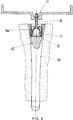
- la fig. 1 montre la prothèse selon l'idée, vue de côté et sectionnée sur un plan vertical médian;
- la fig. 2 montre la prothèse selon l'idée, vue de front et partiellement sectionnée sur un plan vertical passant par l'axe du pivot tibial;
- la fig. 3 montre de manière schématique une version différente de construction du point d'articulation entre le pivot et la composante tibiale;
- la fig. 4 montre la composante fémorale de la prothèse dans la version spéciale, vue du haut;
- la fig. 5 montre la composante fémorale de la prothèse dans la version spéciale, vue du côté gauche, avec la vis de fixation du pivot enfilée dans la fente;
- la fig. 6 est une vue frontale de la composante fémorale de la prothèse dans la version spéciale, sectionnée avec le plan VI-VI de la fig. 2;
- la fig. 7 montre le plat tibial de la prothèse dans la version spéciale, vu du haut et équipé du petit disque interchangeable;
- la fig. 8 est la section avec le plan VIII-VIII de la fig. 7;
- la fig. 9 montre le plat tibial de la prothèse dans la version spéciale, vu du haut et privé du petit disque interchangeable;
- la fig. 10 est la section de la fig. 9 avec le plan X-X;
- la fig. 11 est la représentation d'une série de petits disques interchangeables.
- fig. 1 shows the prosthesis according to the idea, seen from the side and sectioned on a vertical median plane;
- fig. 2 shows the prosthesis according to the idea, seen from the front and partially sectioned on a vertical plane passing through the axis of the tibial pivot;
- fig. 3 schematically shows a different version of construction of the point of articulation between the pivot and the tibial component;
- fig. 4 shows the femoral component of the prosthesis in the special version, seen from above;
- fig. 5 shows the femoral component of the prosthesis in the special version, viewed from the left side, with the pivot fixing screw threaded into the slot;
- fig. 6 is a front view of the femoral component of the prosthesis in the special version, sectioned with the plane VI-VI of FIG. 2;
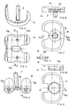
- fig. 7 shows the tibial plate of the prosthesis in the special version, seen from the top and fitted with the small interchangeable disc;
- fig. 8 is the section with the plane VIII-VIII of FIG. 7;
- fig. 9 shows the tibial plate of the prosthesis in the special version, seen from the top and deprived of the small interchangeable disc;
- fig. 10 is the section of FIG. 9 with plane XX;
- fig. 11 is the representation of a series of small interchangeable discs.
Référence les figures 1, 2 et 3, la prothèse en question englobe la prothèse fémorale (1), réalisée en métal et ayant une géométrie qui en permet l'implantation tant sur le genou de gauche que sur celui de droite; le pont central anti-rotation (1a) ainsi que les condyles fémoraux (1b) sont bien visibles dans la fig. 2.Referring to Figures 1, 2 and 3, the prosthesis in question includes the femoral prosthesis (1), made of metal and having a geometry which allows implantation both on the left knee and on the right; the central anti-rotation bridge (1a) as well as the femoral condyles (1b) are clearly visible in fig. 2.
L'union de la composante fémorale (1) au fémur (F) s'effectue au moyen d'une vis (2) que l'on visse de manière axiale dans un pivot (3) conventionnel, fiché dans la spongieuse fémorale.The union of the femoral component (1) to the femur (F) is effected by means of a screw (2) which is screwed axially in a conventional pivot (3), inserted in the cancellous femur.
Il faut prêter une attention particulière à la configuration de la tête (2a) de la vis de jonction (2) dont la tête est en forme de calotte sphérique et qui est nichée dans un siège (1c) conforme, creusé au centre du pont intercondylien (la) de la composante fémorale (1).Particular attention must be paid to the configuration of the head (2a) of the connecting screw (2) whose head is in the form of a spherical cap and which is nestled in a conforming seat (1c), hollowed out in the center of the intercondylar bridge (la) of the femoral component (1).
Ledit siège (1c) présente sur son fond un perçage passant (1d) de diamètre plus grand de la tige filetée de la vis (2) qui peut donc assumer des positions avec différentes inclinations par rapport à l'axe du perçage (1d) susmentionné, comme mis en évidence dans la fig. 2.Said seat (1c) has on its bottom a through bore (1d) of larger diameter of the threaded rod of the screw (2) which can therefore assume positions with different inclinations relative to the axis of the bore (1d) mentioned above , as highlighted in fig. 2.
Cette jonction articulée entre la tête (2a) de la vis (2) et son siège de logement (1c) comporte la réalisation de la désirée jonction articulée entre la composante fémorale (1) et son respectif pivot endomédullaire (3).This articulated junction between the head (2a) of the screw (2) and its housing seat (1c) comprises the realization of the desired articulated junction between the femoral component (1) and its respective endomedullary pivot (3).
De même pour la composante tibiale, formée d'un plat métallique (4) fixé en-dessous d'une plate-forme (5), moulée en polyéthylène à forte densité, et dont la partie supérieure est formée d'une cavité moulée de manière à pouvoir se coupler avec les condyles fémoraux (1b).Likewise for the tibial component, formed of a metal plate (4) fixed below a platform (5), molded from high density polyethylene, and the upper part of which is formed from a molded cavity so as to be able to couple with the femoral condyles (1b).
En effet, le plat tibial (4) présente inférieurement une protubérance (4a) dans laquelle un siège (4b) est creusé; ledit siège ayant une forme sphérique et sur le fond un perçage passant (4c) de diamètre plus grand de la tige filetée de la vis (2) qui se visse de manière axiale dans le pivot (3) fiché dans le canal médullaire du tibia (T).Indeed, the tibial plate (4) has a protrusion (4a) below in which a seat (4b) is hollowed out; said seat having a spherical shape and on the bottom a passing bore (4c) of larger diameter of the rod threaded screw (2) which is screwed axially in the pivot (3) inserted in the medullary canal of the tibia (T).
Il faut souligner que les pivots (3) présentent un filetage à pas large, adapté à la nature spongieuse de l'os, et une surface micro-poreuse apte à favoriser l'ancrage sans ciment.It should be noted that the pivots (3) have a thread with a wide pitch, adapted to the spongy nature of the bone, and a micro-porous surface capable of promoting anchoring without cement.
Deux arrêts en forme d'anneau, anti-rotation et forjettant inférieurement du plat tibial (4) sont représentés dans la fig. 2 avec le numéro (6).Two ring-shaped stops, anti-rotation and lowering of the tibial plate (4) are shown in fig. 2 with number (6).
Toutes les composantes métalliques sont réalisées en alliage de titane ou dans un autre alliage biocompatible. Tout en restant dans le milieu de l'idée en objet, on peut prévoir que le point d'articulation sphérique entre le pivot et la composante fémorale ou tibiale puisse être réalisé à l'interne du pivot même, comme illustré de manière schématique dans la fig. 3, et où ladite forme de réalisation alternative de l'idée a été illustrée uniquement en faisant référence à la composante tibiale.All metal components are made of titanium alloy or another biocompatible alloy. While remaining in the middle of the idea in question, it can be foreseen that the spherical point of articulation between the pivot and the femoral or tibial component can be produced inside the pivot itself, as illustrated schematically in the fig. 3, and where said alternative embodiment of the idea has been illustrated only with reference to the tibial component.
Dans ce cas la tête sphérique (7) de la vis de jonction (8) est nichée dans un siège conforme (9) percé et prévu dans un support adapté (9a) fixé à la base du pivot (10); la composante fémorale ou tibiale doit alors prévoir un siège adapté pour le logement de l'écrou de serrage (11) qui fixe la tige filetée de la susdite vis (8) à la composante même. Référence les figures de 4 à 11, examinons maintenant la configuration assumée par la prothèse en question dans la version spéciale, apte à permettre un réglage du point d'arrêt de la vis sur les composantes fémorale et tibiale.In this case the spherical head (7) of the connecting screw (8) is nestled in a conforming seat (9) drilled and provided in a suitable support (9a) fixed to the base of the pivot (10); the femoral or tibial component must then provide a seat suitable for housing the tightening nut (11) which fixes the threaded rod of the above screw (8) to the component itself. Referring to Figures 4 to 11, let's now examine the configuration assumed by the prosthesis in question in the special version, capable of allowing adjustment of the point where the screw stops on the femoral and tibial components.
La composante fémorale (12) dans cette version spéciale résulte privée du susdit pont intercondylien (la) de manière à préserver le capital osseux.The femoral component (12) in this special version is deprived of the above intercondylar bridge (la) so as to preserve the bone capital.
Dans la version spéciale, la composante fémorale (12) supporte une fente centrale (13) ayant les bords (13a) arrondis et dans laquelle la tête (2a) de la vis (2) qui se visse sur le pivot fémoral a son exact logement.In the special version, the femoral component (12) supports a central slot (13) having rounded edges (13a) and in which the head (2a) of the screw (2) which is screwed on the femoral pivot has its exact housing .
Ainsi que mis en évidence à la fig. 6, la largeur de la fente (13), ainsi que ses bords arrondis (13a) sont tels qu'ils permettent la liberté d'oscillation de la tête (2a) et par conséquent de la tige filetée de la vis (2), tandis que la longueur de la fente (13), clairement visible à la figure 4, permet les déplacements antéro-postérieurs de la vis (2).As highlighted in fig. 6, the width of the slot (13), as well as its rounded edges (13a) are such that they allow freedom of oscillation of the head (2a) and consequently of the threaded rod of the screw (2), while the length of the slot (13), clearly visible in Figure 4, allows the anteroposterior movements of the screw (2).
Référence les figures de 7 à 11, le plat tibial (14) dans la version spéciale de la prothèse en question présente un perçage central (14a) avec embouchure tronconique dans laquelle un petit disque interchangeable (15) a son exact logement; sur ledit petit disque interchangeable (15), en position plus ou moins excentrique, un perçage (16) a été réalisé ayant des bords arrondis (16a) et dans lequel la tête (2a) de la vis (2) qui se visse dans le pivot tibial a son exact logement.Referring to Figures 7 to 11, the tibial plate (14) in the special version of the prosthesis in question has a central bore (14a) with frustoconical mouth in which a small interchangeable disc (15) has its exact housing; on said interchangeable small disc (15), in a more or less eccentric position, a bore (16) has been made having rounded edges (16a) and in which the head (2a) of the screw (2) which screws into the tibial pivot has its exact location.
Le profil concave des bords (16a) des perçages (16) se conjugue parfaitement avec celui convexe de la tête (2a) de la vis (2), permettant ainsi à cette dernière des oscillations par rapport à l'axe du perçage (16). On fait de même remarquer que les petits disques (15) étant en mesure de pivoter dans leurs propres logements (14a), la possibilité de réglage de la vis (2) est vraiment très vaste, vu que on peut l'effectuer soit en choisissant les plusieurs petits disques disponibles, soit à travers une rotation adaptée du petit disque choisi dans son logement du plat tibial.The concave profile of the edges (16a) of the holes (16) combines perfectly with that of the convex head (2a) of the screw (2), thus allowing the latter to oscillate relative to the axis of the hole (16) . We also note that the small discs (15) being able to pivot in their own housings (14a), the possibility of adjusting the screw (2) is really very wide, since it can be done either by choosing the several small discs available, either through a suitable rotation of the small disc chosen in its housing of the tibial plate.
Il faut aussi souligner que la prothèse en question est en mesure d'utiliser, pour le raccordement et la fixation au canal endomédullaire, non seulement des pivots mais bien aussi des coins; lesdits coins devraient alors être équipés d'un perçage fileté conforme dans lequel pourrait s'engager la tige de la vis (2) qui dans ce cas présenterait des longueurs inférieures de celles utilisées avec les pivots. L'utilisation des susdits coins est parfois préférée à celle des pivots, surtout pour la fixation de la composante tibiale de la prothèse.It should also be stressed that the prosthesis in question is able to use, for connection and fixation to the endomedullary canal, not only pivots but also corners; said corners should then be fitted with a conforming threaded hole in which the screw rod (2) could engage, which in this case would have lengths shorter than those used with the pivots. The use of the above corners is sometimes preferred to that of the pivots, especially for fixing the tibial component of the prosthesis.
Finalement on souligne que dans la composante fémorale (12), deux perçages filetés (12a) sont prévus; en position médio-latérale et dans lesquels, si nécessaire, on peut visser des pivots que l'on veut ficher dans l'os fémoral, en renfort ou en alternative du pivot fémoral.Finally it is emphasized that in the femoral component (12), two threaded holes (12a) are provided; in the medio-lateral position and in which, if necessary, we can screw pivots that we want to insert in the femoral bone, as a reinforcement or as an alternative to the femoral pivot.
Claims (5)
Applications Claiming Priority (2)
| Application Number | Priority Date | Filing Date | Title |
|---|---|---|---|
| ITAN910031A IT1253545B (en) | 1991-08-08 | 1991-08-08 | KNEE PROSTHESIS EQUIPPED WITH ARTICULATION BETWEEN FEMORAL AND TIBIAL COMPONENTS AND THE RESPECTIVE ENDOMIDOLLAR PHYTHONES |
| ITAN910031 | 1991-08-08 |
Publications (2)
| Publication Number | Publication Date |
|---|---|
| EP0531263A1 true EP0531263A1 (en) | 1993-03-10 |
| EP0531263B1 EP0531263B1 (en) | 1996-05-29 |
Family
ID=11333539
Family Applications (1)
| Application Number | Title | Priority Date | Filing Date |
|---|---|---|---|
| EP92830439A Expired - Lifetime EP0531263B1 (en) | 1991-08-08 | 1992-08-06 | Knee prosthesis provided with articulations between femoral and tibial components and their respective stems |
Country Status (4)
| Country | Link |
|---|---|
| EP (1) | EP0531263B1 (en) |
| AT (1) | ATE138555T1 (en) |
| DE (1) | DE69211077T2 (en) |
| IT (1) | IT1253545B (en) |
Cited By (14)
| Publication number | Priority date | Publication date | Assignee | Title |
|---|---|---|---|---|
| FR2711510A1 (en) * | 1993-10-28 | 1995-05-05 | Medinov Sa | Device for fixing an intramedullary rod for a total knee prosthesis |
| EP0714645A1 (en) * | 1994-12-01 | 1996-06-05 | JOHNSON & JOHNSON PROFESSIONAL Inc. | Modular knee prosthesis |
| EP0781535A3 (en) * | 1995-12-29 | 1997-12-03 | JOHNSON & JOHNSON PROFESSIONAL Inc. | Femoral stem attachment for a modular knee prosthesis |
| US5824097A (en) * | 1996-07-23 | 1998-10-20 | Johnson & Johnson Professional, Inc. | Medical fastening system |
| US5879391A (en) * | 1996-09-30 | 1999-03-09 | Johnson & Johnson Professional, Inc. | Modular prosthesis |
| JPH11309162A (en) * | 1998-03-30 | 1999-11-09 | Johnson & Johnson Professional Inc | Medical clamping device and modular artificial joint device |
| JP2000107211A (en) * | 1998-09-09 | 2000-04-18 | Johnson & Johnson Professional Inc | Femur stem fitting method for module type knee prothesis |
| US6063122A (en) * | 1998-06-22 | 2000-05-16 | Johnson & Johnson Professional, Inc. | Jack screw adapter for joint prosthesis |
| US6071311A (en) * | 1998-08-14 | 2000-06-06 | Johnson & Johnson Professional, Inc. | Cylindrical box femoral stem |
| US6306172B1 (en) | 1999-01-28 | 2001-10-23 | Johnson & Johnson Professional, Inc. | Modular tibial insert for prosthesis system |
| US6709461B2 (en) | 1999-02-03 | 2004-03-23 | Depuy Products, Inc. | Modular joint prosthesis system |
| US8110005B2 (en) | 2000-04-10 | 2012-02-07 | Biomet Manufacturing Corp. | Modular prosthesis and use thereof for replacing a radial head |
| US8920509B2 (en) | 2000-04-10 | 2014-12-30 | Biomet Manufacturing, Llc | Modular radial head prosthesis |
| US9439784B2 (en) | 2000-04-10 | 2016-09-13 | Biomet Manufacturing, Llc | Modular radial head prosthesis |
Families Citing this family (2)
| Publication number | Priority date | Publication date | Assignee | Title |
|---|---|---|---|---|
| US7998217B1 (en) | 2005-02-02 | 2011-08-16 | Biomet Manufacturing Corp. | Modular offset stem implants |
| US7842093B2 (en) | 2006-07-18 | 2010-11-30 | Biomet Manufacturing Corp. | Method and apparatus for a knee implant |
Citations (4)
| Publication number | Priority date | Publication date | Assignee | Title |
|---|---|---|---|---|
| US3916451A (en) * | 1974-10-25 | 1975-11-04 | Frederick F Buechel | Floating center prosthetic joint |
| US4822366A (en) * | 1986-10-16 | 1989-04-18 | Boehringer Mannheim Corporation | Modular knee prosthesis |
| EP0376658A2 (en) * | 1988-12-27 | 1990-07-04 | JOHNSON & JOHNSON ORTHOPAEDICS INC. | Modular knee prosthesis |
| US4985037A (en) * | 1989-05-22 | 1991-01-15 | Petersen Thomas D | Universal modular prosthesis stem extension |
-
1991
- 1991-08-08 IT ITAN910031A patent/IT1253545B/en active IP Right Grant
-
1992
- 1992-08-06 EP EP92830439A patent/EP0531263B1/en not_active Expired - Lifetime
- 1992-08-06 DE DE69211077T patent/DE69211077T2/en not_active Expired - Fee Related
- 1992-08-06 AT AT92830439T patent/ATE138555T1/en not_active IP Right Cessation
Patent Citations (4)
| Publication number | Priority date | Publication date | Assignee | Title |
|---|---|---|---|---|
| US3916451A (en) * | 1974-10-25 | 1975-11-04 | Frederick F Buechel | Floating center prosthetic joint |
| US4822366A (en) * | 1986-10-16 | 1989-04-18 | Boehringer Mannheim Corporation | Modular knee prosthesis |
| EP0376658A2 (en) * | 1988-12-27 | 1990-07-04 | JOHNSON & JOHNSON ORTHOPAEDICS INC. | Modular knee prosthesis |
| US4985037A (en) * | 1989-05-22 | 1991-01-15 | Petersen Thomas D | Universal modular prosthesis stem extension |
Cited By (23)
| Publication number | Priority date | Publication date | Assignee | Title |
|---|---|---|---|---|
| FR2711510A1 (en) * | 1993-10-28 | 1995-05-05 | Medinov Sa | Device for fixing an intramedullary rod for a total knee prosthesis |
| EP0714645A1 (en) * | 1994-12-01 | 1996-06-05 | JOHNSON & JOHNSON PROFESSIONAL Inc. | Modular knee prosthesis |
| US5556433A (en) * | 1994-12-01 | 1996-09-17 | Johnson & Johnson Professional, Inc. | Modular knee prosthesis |
| AU699390B2 (en) * | 1994-12-01 | 1998-12-03 | Depuy Orthopaedics, Inc. | Modular knee prosthesis |
| EP0781535A3 (en) * | 1995-12-29 | 1997-12-03 | JOHNSON & JOHNSON PROFESSIONAL Inc. | Femoral stem attachment for a modular knee prosthesis |
| US5824097A (en) * | 1996-07-23 | 1998-10-20 | Johnson & Johnson Professional, Inc. | Medical fastening system |
| US6171342B1 (en) | 1996-07-23 | 2001-01-09 | Depuy Orthopaedics, Inc. | Medical fastening system |
| US5879391A (en) * | 1996-09-30 | 1999-03-09 | Johnson & Johnson Professional, Inc. | Modular prosthesis |
| JPH11309162A (en) * | 1998-03-30 | 1999-11-09 | Johnson & Johnson Professional Inc | Medical clamping device and modular artificial joint device |
| US6063122A (en) * | 1998-06-22 | 2000-05-16 | Johnson & Johnson Professional, Inc. | Jack screw adapter for joint prosthesis |
| US6071311A (en) * | 1998-08-14 | 2000-06-06 | Johnson & Johnson Professional, Inc. | Cylindrical box femoral stem |
| JP2000107211A (en) * | 1998-09-09 | 2000-04-18 | Johnson & Johnson Professional Inc | Femur stem fitting method for module type knee prothesis |
| US6527807B1 (en) | 1998-09-09 | 2003-03-04 | Johnson & Johnson Professional, Inc. | Femoral stem attachment for a modular knee prosthesis |
| US6306172B1 (en) | 1999-01-28 | 2001-10-23 | Johnson & Johnson Professional, Inc. | Modular tibial insert for prosthesis system |
| US6709461B2 (en) | 1999-02-03 | 2004-03-23 | Depuy Products, Inc. | Modular joint prosthesis system |
| US8110005B2 (en) | 2000-04-10 | 2012-02-07 | Biomet Manufacturing Corp. | Modular prosthesis and use thereof for replacing a radial head |
| US8114163B2 (en) | 2000-04-10 | 2012-02-14 | Biomet Manufacturing Corp. | Method and apparatus for adjusting height and angle for a radial head |
| US8366781B2 (en) | 2000-04-10 | 2013-02-05 | Biomet Manufacturing Corp. | Modular prosthesis and use thereof for replacing a radial head |
| US8425615B2 (en) | 2000-04-10 | 2013-04-23 | Biomet Manufacturing Corp. | Method and apparatus for adjusting height and angle for a radial head |
| US8920509B2 (en) | 2000-04-10 | 2014-12-30 | Biomet Manufacturing, Llc | Modular radial head prosthesis |
| US9333084B2 (en) | 2000-04-10 | 2016-05-10 | Biomet Manufacturing, Llc | Modular prosthesis and use thereof for replacing a radial head |
| US9439784B2 (en) | 2000-04-10 | 2016-09-13 | Biomet Manufacturing, Llc | Modular radial head prosthesis |
| US9579208B2 (en) | 2000-04-10 | 2017-02-28 | Biomet Manufacturing, Llc | Modular radial head prosthesis |
Also Published As
| Publication number | Publication date |
|---|---|
| ATE138555T1 (en) | 1996-06-15 |
| DE69211077D1 (en) | 1996-07-04 |
| ITAN910031A1 (en) | 1993-02-08 |
| IT1253545B (en) | 1995-08-08 |
| DE69211077T2 (en) | 1997-01-23 |
| EP0531263B1 (en) | 1996-05-29 |
| ITAN910031A0 (en) | 1991-08-08 |
Similar Documents
| Publication | Publication Date | Title |
|---|---|---|
| EP0531263B1 (en) | Knee prosthesis provided with articulations between femoral and tibial components and their respective stems | |
| EP1025819B1 (en) | Knee prosthesis with an insert, which is mobile in relation to a post | |
| EP0545833B1 (en) | Knee prosthesis | |
| EP0684804B1 (en) | Total knee prosthesis | |
| EP0549480B1 (en) | Modular humeral prosthesis | |
| EP1470800B1 (en) | Modular guide post for knee prothesis with posterior stabilisation. | |
| US5755804A (en) | Endoprosthetic knee joint | |
| EP1354571B1 (en) | Total knee prothesis | |
| EP1041944A1 (en) | Knee prosthesis femoral implant and orthopaedic equipment set comprising such a femoral implant | |
| CH618873A5 (en) | ||
| FR2773469A1 (en) | SURGICAL EQUIPMENT FOR THE IMPLANTATION OF A TOTAL SHOULDER PROSTHESIS, AND TOTAL SHOULDER PROSTHESIS | |
| EP0890347A1 (en) | Knee joint prosthesis | |
| EP0598734A1 (en) | Bi-axial elbow joint replacement | |
| FR2695313A1 (en) | Socket implant, esp. shoulder prosthesis - is designed to allow use of thin metallic base plate | |
| FR2773059A1 (en) | KNEE PROSTHESIS | |
| FR2755847A1 (en) | Shoulder joint articulation prosthesis | |
| FR2716619A1 (en) | Tibial component for knee joint replacement prosthesis | |
| WO2006040434A2 (en) | Total knee prosthesis and range of elements for producing said prosthesis | |
| EP0898946A1 (en) | Humeral head prosthesis | |
| FR2897527A1 (en) | Cup for cotyloidal implant, has tapered part and recess cooperating with outer and inner surfaces of different types of inserts by friction and by detent, respectively, where cap is made of osteo-conductor metal such as titanium alloy | |
| FR2626168A1 (en) | Modular hip prosthesis | |
| EP0645126A2 (en) | Posteriorly stabilized bicondylar knee joint prosthesis | |
| BE1008201A3 (en) | Total knee prosthesis. | |
| FR2917282A1 (en) | Final recess forming tool adaptor for positioning shoulder prosthesis, has stop setting unit limiting penetration of rasp of tool for implantation of reverse prosthesis as well as standard prosthesis of same model using same handle and rasp | |
| FR2628316A1 (en) | Whole knee prosthesis - has one piece implanted at end of femur, other at end of tibia articulating around cross member of T=piece |
Legal Events
| Date | Code | Title | Description |
|---|---|---|---|
| PUAI | Public reference made under article 153(3) epc to a published international application that has entered the european phase |
Free format text: ORIGINAL CODE: 0009012 |
|
| AK | Designated contracting states |
Kind code of ref document: A1 Designated state(s): AT BE CH DE DK ES FR GB GR IT LI LU MC NL PT SE |
|
| 17P | Request for examination filed |
Effective date: 19930803 |
|
| 17Q | First examination report despatched |
Effective date: 19950328 |
|
| GRAH | Despatch of communication of intention to grant a patent |
Free format text: ORIGINAL CODE: EPIDOS IGRA |
|
| GRAA | (expected) grant |
Free format text: ORIGINAL CODE: 0009210 |
|
| AK | Designated contracting states |
Kind code of ref document: B1 Designated state(s): AT BE CH DE DK ES FR GB GR IT LI LU MC NL PT SE |
|
| PG25 | Lapsed in a contracting state [announced via postgrant information from national office to epo] |
Ref country code: NL Free format text: LAPSE BECAUSE OF FAILURE TO SUBMIT A TRANSLATION OF THE DESCRIPTION OR TO PAY THE FEE WITHIN THE PRESCRIBED TIME-LIMIT Effective date: 19960529 Ref country code: GR Free format text: LAPSE BECAUSE OF FAILURE TO SUBMIT A TRANSLATION OF THE DESCRIPTION OR TO PAY THE FEE WITHIN THE PRESCRIBED TIME-LIMIT Effective date: 19960529 Ref country code: ES Free format text: THE PATENT HAS BEEN ANNULLED BY A DECISION OF A NATIONAL AUTHORITY Effective date: 19960529 Ref country code: DK Effective date: 19960529 Ref country code: AT Effective date: 19960529 |
|
| REF | Corresponds to: |
Ref document number: 138555 Country of ref document: AT Date of ref document: 19960615 Kind code of ref document: T |
|
| REF | Corresponds to: |
Ref document number: 69211077 Country of ref document: DE Date of ref document: 19960704 |
|
| PGFP | Annual fee paid to national office [announced via postgrant information from national office to epo] |
Ref country code: GB Payment date: 19960808 Year of fee payment: 5 |
|
| PGFP | Annual fee paid to national office [announced via postgrant information from national office to epo] |
Ref country code: FR Payment date: 19960809 Year of fee payment: 5 |
|
| ITF | It: translation for a ep patent filed |
Owner name: STUDIO TECN. ING. CLAUDIO BALDI |
|
| PG25 | Lapsed in a contracting state [announced via postgrant information from national office to epo] |
Ref country code: SE Effective date: 19960829 Ref country code: PT Effective date: 19960829 |
|
| REG | Reference to a national code |
Ref country code: CH Ref legal event code: NV Representative=s name: BOVARD AG PATENTANWAELTE |
|
| PG25 | Lapsed in a contracting state [announced via postgrant information from national office to epo] |
Ref country code: LU Free format text: LAPSE BECAUSE OF NON-PAYMENT OF DUE FEES Effective date: 19960831 Ref country code: BE Effective date: 19960831 |
|
| GBT | Gb: translation of ep patent filed (gb section 77(6)(a)/1977) |
Effective date: 19960902 |
|
| NLV1 | Nl: lapsed or annulled due to failure to fulfill the requirements of art. 29p and 29m of the patents act | ||
| PGFP | Annual fee paid to national office [announced via postgrant information from national office to epo] |
Ref country code: CH Payment date: 19961202 Year of fee payment: 5 |
|
| BERE | Be: lapsed |
Owner name: GEMED LTD Effective date: 19960831 |
|
| PG25 | Lapsed in a contracting state [announced via postgrant information from national office to epo] |
Ref country code: MC Effective date: 19970228 |
|
| PLBE | No opposition filed within time limit |
Free format text: ORIGINAL CODE: 0009261 |
|
| STAA | Information on the status of an ep patent application or granted ep patent |
Free format text: STATUS: NO OPPOSITION FILED WITHIN TIME LIMIT |
|
| 26N | No opposition filed | ||
| PG25 | Lapsed in a contracting state [announced via postgrant information from national office to epo] |
Ref country code: GB Free format text: LAPSE BECAUSE OF NON-PAYMENT OF DUE FEES Effective date: 19970806 |
|
| PG25 | Lapsed in a contracting state [announced via postgrant information from national office to epo] |
Ref country code: LI Free format text: LAPSE BECAUSE OF NON-PAYMENT OF DUE FEES Effective date: 19970831 Ref country code: CH Free format text: LAPSE BECAUSE OF NON-PAYMENT OF DUE FEES Effective date: 19970831 |
|
| PGFP | Annual fee paid to national office [announced via postgrant information from national office to epo] |
Ref country code: DE Payment date: 19971024 Year of fee payment: 6 |
|
| GBPC | Gb: european patent ceased through non-payment of renewal fee |
Effective date: 19970806 |
|
| REG | Reference to a national code |
Ref country code: CH Ref legal event code: PL |
|
| PG25 | Lapsed in a contracting state [announced via postgrant information from national office to epo] |
Ref country code: FR Free format text: LAPSE BECAUSE OF NON-PAYMENT OF DUE FEES Effective date: 19980430 |
|
| REG | Reference to a national code |
Ref country code: FR Ref legal event code: ST |
|
| PG25 | Lapsed in a contracting state [announced via postgrant information from national office to epo] |
Ref country code: DE Free format text: LAPSE BECAUSE OF NON-PAYMENT OF DUE FEES Effective date: 19990601 |
|
| PG25 | Lapsed in a contracting state [announced via postgrant information from national office to epo] |
Ref country code: IT Free format text: LAPSE BECAUSE OF NON-PAYMENT OF DUE FEES;WARNING: LAPSES OF ITALIAN PATENTS WITH EFFECTIVE DATE BEFORE 2007 MAY HAVE OCCURRED AT ANY TIME BEFORE 2007. THE CORRECT EFFECTIVE DATE MAY BE DIFFERENT FROM THE ONE RECORDED. Effective date: 20050806 |