EP0530822B1 - Guide device for vibration driven motor - Google Patents
Guide device for vibration driven motor Download PDFInfo
- Publication number
- EP0530822B1 EP0530822B1 EP92115162A EP92115162A EP0530822B1 EP 0530822 B1 EP0530822 B1 EP 0530822B1 EP 92115162 A EP92115162 A EP 92115162A EP 92115162 A EP92115162 A EP 92115162A EP 0530822 B1 EP0530822 B1 EP 0530822B1
- Authority
- EP
- European Patent Office
- Prior art keywords
- vibration
- guide
- driven motor
- motor according
- engaged
- Prior art date
- Legal status (The legal status is an assumption and is not a legal conclusion. Google has not performed a legal analysis and makes no representation as to the accuracy of the status listed.)
- Expired - Lifetime
Links
- 230000006835 compression Effects 0.000 description 12
- 238000007906 compression Methods 0.000 description 12
- 238000006243 chemical reaction Methods 0.000 description 3
- 238000006073 displacement reaction Methods 0.000 description 3
- 230000000694 effects Effects 0.000 description 2
- 230000000452 restraining effect Effects 0.000 description 2
- 238000003466 welding Methods 0.000 description 2
- 230000001419 dependent effect Effects 0.000 description 1
- 230000002542 deteriorative effect Effects 0.000 description 1
- 230000001771 impaired effect Effects 0.000 description 1
- 239000002184 metal Substances 0.000 description 1
Images


Classifications
-
- H—ELECTRICITY
- H02—GENERATION; CONVERSION OR DISTRIBUTION OF ELECTRIC POWER
- H02N—ELECTRIC MACHINES NOT OTHERWISE PROVIDED FOR
- H02N2/00—Electric machines in general using piezoelectric effect, electrostriction or magnetostriction
- H02N2/02—Electric machines in general using piezoelectric effect, electrostriction or magnetostriction producing linear motion, e.g. actuators; Linear positioners ; Linear motors
- H02N2/08—Electric machines in general using piezoelectric effect, electrostriction or magnetostriction producing linear motion, e.g. actuators; Linear positioners ; Linear motors using travelling waves, i.e. Rayleigh surface waves
Definitions
- the present invention relates to a vibration driven motor according to the preamble portion of claim 1 and, more particularly, to a linear shaped vibration wave driven motor for urging an elastic member in which a travelling wave is formed against a rail shaped stator, and moving the elastic member along the rail shaped stator.
- An elliptic metal elastic member 1 has a projection la formed on the sliding surface side, and a piezo-electric element 2 is bonded on the upper surface of the elastic member, thus forming a vibrator.
- a travelling vibration wave is formed.
- the generation principle of the travelling vibration wave and the structure of the piezo-electric element 2 are known to those skilled in the art, and a detailed description thereof will be omitted. Briefly speaking, when AC voltages having 90° time phases are applied to two groups of driving piezo-electric elements which are positionally shifted by 90°, a travelling vibration wave is formed.
- a rail shaped stator 8 is in frictional contact with the elastic member 1.
- the stator 8 is fixed to a bottom plate 10 of a motor case, and is in contact with the elastic member 1 by a compression spring 3 through a vibration insulating member 5 (e.g., a felt).
- a planar supporting plate 6 is fixed to the elastic member 1. The central portion of the supporting plate 6 is fixed by a block shaped supporting member 7, and the supporting plate 6 supports the elastic member 1.
- the elastic member 1 is supported on a base 4 through the supporting plate 6 and the supporting member 7, and the base 4 is supported by restriction members 9 for restricting displacements other than that in a prospective moving direction B Y .
- the elastic member 1 When a travelling vibration wave is formed in the elastic member 1, the elastic member 1 is moved along the rail shaped stator 8 by the frictional force between the rail shaped stator 8 and the elastic member 1, and the base 4 as well as the other members 3, 5, 6, and 7 are moved in the direction B Y along the restriction members 9 accordingly.
- the frictional driving force generated in this case is applied on a portion of the elastic member 1, and is shifted from the supporting portion. For this reason, a moment acts on the elastic member 1, and the elastic member 1 is forced to shift in the directions B X and B Y .
- the supporting plate 6 has an X shape, as shown in Fig. 8, and its four distal ends are joined to the inner side surfaces of the elastic member 1 by, e.g., spot welding.
- the central portion of the supporting plate 6 is rigidly clamped by the supporting member 7, and the supporting member 7 is fixed to the base 4. For this reason, even when the moment acts on the elastic member 1, the elastic member 1 can be smoothly linearly moved together with the base 4 without being rotated or cluttering.
- this motor can perform position control of an intermittent driving operation with high precision, it is proposed to use the motor as a print head driving source in, e.g., a thermal jet printer.
- the print head is mounted on a carriage (not shown) attached to the base 4, and is linearly reciprocally moved.
- the bottom plate 10 attached with the rail shaped stator 8 and restriction members 9 is a thin plate, it considerably deforms (e.g., warps).
- the restriction members 9 and the rail shaped stator 8 are attached to the bottom plate 10, deformation of these members is worsened.
- a vibration driven motor comprises
- the object underlying the present invention is to further develop the vibration driven motor according to the aforementioned state of the art to the effect that a stable motor output can reliably be obtained, and to provide an improved vibration driven system using such vibration driven motor.
- the first guide portion and the second guide portion are formed in side surfaces of the rail shaped contact member, so that the first and second guide portions are integrally formed with the contact member.
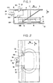
- Figs. 1 and 2 are respectively a side view and a partially cutaway plan view showing the first embodiment of a linear shaped vibration driven motor according to the present invention.
- a vibration member (in the following referred to as vibrator) used in this embodiment is prepared by bonding a piezo-electric element 2 as an electro-mechanical energy conversion element on one surface of an elliptic elastic member 1 like in the prior art.
- a large number of comb shaped projections (not shown) are formed on a driving surface, opposite to the piezo-electric element 2, of the elastic member 1 in the travelling direction of a travelling wave.
- a supporting plate 6 is joined between opposing linear portions of the elastic member 1 by a joint means such as spot welding.
- the lower end portion of a supporting member 7 depending from a base 4 located above the supporting plate 6 is attached to the supporting plate 6, thus integrally assembling the base 4 and the vibrator.
- a compression leaf spring 3 is obliquely arranged between the base 4 and the elastic member 1, as shown in Fig. 1.
- the linear driving portion of the elastic member 1 to be driven is pressed against a contact or rail portion 8A of a rail shaped contact member 8 (in the following referred to as rail shaped stator 8; to be described below) by the biasing force of the compression spring 3 through a vibration insulating member 5 such as a felt interposed between the lower end portion of the compression spring 3 and the elastic member 1.
- Guide portions or grooves 9A and 9B are respectively formed in the upper surface and the outer side surface of the rail shaped stator 8 of this embodiment along the longitudinal direction.
- the rail portion 8A having proper elasticity is formed by a lateral groove 8B on the lower surface portion of the rail shaped stator 8.
- a bridge portion 4A is formed on one side of the base 4 to extend over the rail shaped stator 8, and shaft rods 12 are fixed to the front and rear portions of one side surface of the base 4. Roller bearings 11 whose displacements in a direction B Y are restricted, are rotatably attached to the distal ends of the shaft rods 12 to be fitted in the guide groove 9A.
- a roller compression spring 15 is attached to the bridge portion 4A of the base 4 through a spring supporting plate 16.
- a shaft rod 14 is fixed to the distal end of the roller compression spring 15.
- a roller bearing 13 whose displacement in a direction B Z is restricted, is rotatably attached to the shaft rod 14 to be fitted in the guide groove 9B, and is biased by the biasing force of the spring 15 in a direction B X different from the direction B Y by 90°, thereby preventing cluttering of the base 4 in the direction B X .
- the roller bearing 11 is engaged with the groove 9A having a width slightly wider than that of the roller bearing, and rolls along the groove 9A. Since the roller bearing 13 is biased in the direction B X by the spring 15, the roller bearing 11 rolls while being pressed against one inner side surface of the groove 9A. Thus, the base 4 can be smoothly moved in the direction B Y without cluttering in the direction B X .
- the elastic member 1 is moved.
- the vibrator including the elastic member 1 and the piezo-electric element 2 may be fixed and the stator 8 may be movably arranged, thus obtaining the same effect as described above.
- the supporting member 7 is engaged with the stator 8
- the base 4 is engaged with the supporting member 7.
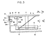
- Fig. 3 shows the second embodiment.
- the roller bearings 11 and 13 are fitted in the guide grooves 9A and 9B.
- first ball shaped roller bearings 17, and a second ball shaped roller bearing 18 are arranged in place of the roller bearings.
- a notched portion 30 having an L shaped section to be engaged with the first ball shaped roller bearings 17 is formed in the inner side surface of the upper portion of the rail shaped stator 8, and a recessed groove 31 in which the second ball shaped roller bearing 18 is fitted to have a small gap is formed in the side surface opposite to the notched portion 30.
- the rail shaped stator 8 is clamped in a direction B X between the two first ball shaped roller bearings 17 arranged in the back-and-forth direction (a direction B Y ), and the second ball shaped roller bearing 18.
- the second ball shaped roller bearing 18 is urged against an inner wall surface 31d of the recessed groove 31 by a compression spring 15, and the first ball shaped roller bearings 17 are urged against a guide surface 30A of the notched portion 30 by a reaction force of the biasing force of a compression spring 3. Since a moment in a direction M 1 in Fig. 3 acts by the weights of a base 4, an elastic member 1, and the like, the roller bearing 18 is urged against a guide surface 31c, thus maintaining the position of the base 4.
- roller bearing 18 Since the roller bearing 18 is biased in the direction B X by the compression spring 15 and is urged against the guide surface 31d, the degree of freedom of the base 4 in the direction B X is restricted by a guide surface 30B through the roller bearings 17.
- the elastic member 1 and the base 4 can be smoothly reciprocally driven in the direction B Y without cluttering in the directions B X and B Z by the guide surfaces 30A, 30B, and 31c to 31e.
- Fig. 4 shows the third embodiment of a linear shaped vibration driven motor according to the present invention.
- a vibrator in contrast to the above embodiment, is formed with a driving surface facing down, and a rail surface is formed facing up on the lower portion of a rail shaped stator 8.
- first ball shaped roller bearings 17 and a second ball shaped roller bearing 18 are provided to a base 4, and the second ball shaped roller bearing 18 is fitted in a recessed groove 31 of the rail shaped stator 8.
- the first ball shaped roller bearings 17 are fitted in a similar groove 40 to have a small gap, and contact guide surfaces 40A and 40B are formed on the inner wall surfaces of the groove 40.
- the outer diameter of the second ball shaped roller bearing 18 is formed to be slightly smaller than the opening width of the recessed groove 31, and when the roller bearing 18 contacts a surface 31c, it is slightly separated from a surface 31e. For this reason, even when a moment M 2 acts, the base 4 is not inclined in the direction M 2 , and the second roller bearing 18 contacts the guide surface 31e to maintain the position of the base 4.
- Shaft rods 12 and 14 do not extend through the first and second ball shaped roller bearings 17 and 18. Therefore, contact surfaces between the first and second ball shaped roller bearings 17 and 18 and the guide surfaces are smooth spherical surfaces.
- Fig. 5 shows the fourth embodiment of a linear shaped vibration driven motor according to the present invention.
- Fig. 5 illustrates only a rail shaped stator 8.
- first and second ball shaped roller bearings 17 and 18 are fitted in grooves having a recess shaped section or a notched portion having an L shaped section.
- these roller bearings are fitted in groove portions 50 and 51 each having a wedge shaped section.
- the constant compression force of the vibrator can be maintained without being influenced by a warp of the bottom plate or the rail, and a stable motor output can be obtained.
Description
- The present invention relates to a vibration driven motor according to the preamble portion of
claim 1 and, more particularly, to a linear shaped vibration wave driven motor for urging an elastic member in which a travelling wave is formed against a rail shaped stator, and moving the elastic member along the rail shaped stator. - As a conventional linear shaped vibration driven motor of this type, a motor shown in Figs. 6 and 7 is known.
- An elliptic metal
elastic member 1 has a projection la formed on the sliding surface side, and a piezo-electric element 2 is bonded on the upper surface of the elastic member, thus forming a vibrator. When an AC voltage is applied to the piezo-electric element 2, a travelling vibration wave is formed. The generation principle of the travelling vibration wave and the structure of the piezo-electric element 2 are known to those skilled in the art, and a detailed description thereof will be omitted. Briefly speaking, when AC voltages having 90° time phases are applied to two groups of driving piezo-electric elements which are positionally shifted by 90°, a travelling vibration wave is formed. A rail shapedstator 8 is in frictional contact with theelastic member 1. Thestator 8 is fixed to abottom plate 10 of a motor case, and is in contact with theelastic member 1 by acompression spring 3 through a vibration insulating member 5 (e.g., a felt). A planar supportingplate 6 is fixed to theelastic member 1. The central portion of the supportingplate 6 is fixed by a block shaped supportingmember 7, and the supportingplate 6 supports theelastic member 1. - The
elastic member 1 is supported on abase 4 through the supportingplate 6 and the supportingmember 7, and thebase 4 is supported byrestriction members 9 for restricting displacements other than that in a prospective moving direction BY. - When a travelling vibration wave is formed in the
elastic member 1, theelastic member 1 is moved along the railshaped stator 8 by the frictional force between the railshaped stator 8 and theelastic member 1, and thebase 4 as well as theother members restriction members 9 accordingly. The frictional driving force generated in this case is applied on a portion of theelastic member 1, and is shifted from the supporting portion. For this reason, a moment acts on theelastic member 1, and theelastic member 1 is forced to shift in the directions BX and BY. - The supporting
plate 6 has an X shape, as shown in Fig. 8, and its four distal ends are joined to the inner side surfaces of theelastic member 1 by, e.g., spot welding. The central portion of the supportingplate 6 is rigidly clamped by the supportingmember 7, and the supportingmember 7 is fixed to thebase 4. For this reason, even when the moment acts on theelastic member 1, theelastic member 1 can be smoothly linearly moved together with thebase 4 without being rotated or cluttering. - Since this motor can perform position control of an intermittent driving operation with high precision, it is proposed to use the motor as a print head driving source in, e.g., a thermal jet printer. The print head is mounted on a carriage (not shown) attached to the
base 4, and is linearly reciprocally moved. - However, in the above-mentioned prior art, since the rail
shaped stator 8 and therestriction members 9 are separately formed, and are elongated in the direction BY, the rail shaped stator and the restriction members considerably deform. For this reason, it is difficult to precisely form the rail sliding surface and the carriage guide portion of the restriction members with high flatness. - Furthermore, since the
bottom plate 10 attached with the railshaped stator 8 andrestriction members 9 is a thin plate, it considerably deforms (e.g., warps). When therestriction members 9 and the railshaped stator 8 are attached to thebottom plate 10, deformation of these members is worsened. - For this reason, the parallelness of the carriage guide surfaces of the two
restriction members 9 is impaired, and the inclination of the carriage locally changes upon movement of the carriage in the direction BY. As a result, the gap between the rail sliding surface and the carriage also changes. - As described above, since the
elastic member 1 is attached to the carriage through the supporting member, and thecompression spring 3 is also attached to the carriage, when the gap between the rail sliding surface and the carriage locally changes in the direction BY, the compression force to be applied to theelastic member 1 varies. Thus, a stable driving force for the motor cannot be obtained. When the inclination of the carriage locally changes, since the vibrator is inclined accordingly, a contact state between the rail sliding surface and the vibrator is worsened, thus deteriorating motor performance. A further vibration driven motor is known from the document JP-A-31 55 375 forming the preamble portion ofclaim 1. - According to this state of the art, a vibration driven motor comprises
- a vibration member consisting of an electromechanical energy conversion element and an elastic member, and being responsive to an applied electrical signal for generating a vibration therein,
- a slide rail which has an upper surface serving as a contact portion which is in contact with the vibration member, the vibration generated in the vibration member effecting relative movement between the vibration member and the slide rail,
- a first guide portion engaged with a first guide arrangement consisting of rollers for restraining the horizontal position, for preventing the vibration member from sliding relative to the slide rail in a first direction, as well as
- a second guide portion engaged with a second guide arrangement consisting of rollers for restraining the upward position, for preventing the vibration member from sliding relative to the slide rail in a second direction which is different from the first direction.
- Accordingly, the object underlying the present invention is to further develop the vibration driven motor according to the aforementioned state of the art to the effect that a stable motor output can reliably be obtained, and to provide an improved vibration driven system using such vibration driven motor.
- This object is solved by the features indicated in the characterizing portion of
claim 1 and the features set forth inclaim 8, respectively. Advantageously developed embodiments of the invention are subject-matter of thedependent claims 2 to 7 and 9. - According to the invention, the first guide portion and the second guide portion are formed in side surfaces of the rail shaped contact member, so that the first and second guide portions are integrally formed with the contact member. By these measures it can reliably be assured that the first and second guide portions extend in parallel to each other so that an unstable contact state between the vibration member and the contact member is prevented, resulting in a stable motor output.
-
- Fig. 1 is a side view showing the first embodiment of a linear shaped vibration driven motor according to the present invention;
- Fig. 2 is a partially cutaway plan view of Fig. 1;
- Fig. 3 is a side view of the second embodiment;
- Fig. 4 is a side view of the third embodiment;
- Fig. 5 is a side view of the fourth embodiment;
- Fig. 6 is a side view of a conventional linear shaped vibration driven motor;
- Fig. 7 is a plan view of Fig. 6; and
- Fig. 8 is a plan view of the supporting plate shown in Fig. 6.
- Figs. 1 and 2 are respectively a side view and a partially cutaway plan view showing the first embodiment of a linear shaped vibration driven motor according to the present invention.
- A vibration member (in the following referred to as vibrator) used in this embodiment is prepared by bonding a piezo-
electric element 2 as an electro-mechanical energy conversion element on one surface of an ellipticelastic member 1 like in the prior art. A large number of comb shaped projections (not shown) are formed on a driving surface, opposite to the piezo-electric element 2, of theelastic member 1 in the travelling direction of a travelling wave. A supportingplate 6 is joined between opposing linear portions of theelastic member 1 by a joint means such as spot welding. The lower end portion of a supportingmember 7 depending from abase 4 located above the supportingplate 6 is attached to the supportingplate 6, thus integrally assembling thebase 4 and the vibrator. Acompression leaf spring 3 is obliquely arranged between thebase 4 and theelastic member 1, as shown in Fig. 1. The linear driving portion of theelastic member 1 to be driven is pressed against a contact orrail portion 8A of a rail shaped contact member 8 (in the following referred to as railshaped stator 8; to be described below) by the biasing force of thecompression spring 3 through avibration insulating member 5 such as a felt interposed between the lower end portion of thecompression spring 3 and theelastic member 1. - Guide portions or
grooves shaped stator 8 of this embodiment along the longitudinal direction. Therail portion 8A having proper elasticity is formed by alateral groove 8B on the lower surface portion of the railshaped stator 8. - A
bridge portion 4A is formed on one side of thebase 4 to extend over the railshaped stator 8, andshaft rods 12 are fixed to the front and rear portions of one side surface of thebase 4.Roller bearings 11 whose displacements in a direction BY are restricted, are rotatably attached to the distal ends of theshaft rods 12 to be fitted in theguide groove 9A. - A
roller compression spring 15 is attached to thebridge portion 4A of thebase 4 through aspring supporting plate 16. Ashaft rod 14 is fixed to the distal end of theroller compression spring 15. A roller bearing 13 whose displacement in a direction BZ is restricted, is rotatably attached to theshaft rod 14 to be fitted in theguide groove 9B, and is biased by the biasing force of thespring 15 in a direction BX different from the direction BY by 90°, thereby preventing cluttering of thebase 4 in the direction BX. - When a high-frequency voltage of about 30 kHz is applied from a power supply (not shown) to the piezo-
electric element 2, a traveling vibration wave is excited in theelastic member 1 by the known principle, and theelastic member 1, thebase 4, and themembers base 4 are moved in the direction By along theguide grooves stator 8, by the frictional force between theelastic member 1 and the rail shapedstator 8. - At this time, the
roller bearing 11 is engaged with thegroove 9A having a width slightly wider than that of the roller bearing, and rolls along thegroove 9A. Since theroller bearing 13 is biased in the direction BX by thespring 15, theroller bearing 11 rolls while being pressed against one inner side surface of thegroove 9A. Thus, thebase 4 can be smoothly moved in the direction BY without cluttering in the direction BX. - In the above embodiment, the
elastic member 1 is moved. The vibrator including theelastic member 1 and the piezo-electric element 2 may be fixed and thestator 8 may be movably arranged, thus obtaining the same effect as described above. In this case, of course, the supportingmember 7 is engaged with thestator 8, and thebase 4 is engaged with the supportingmember 7. When a print head is arranged on thebase 4, the present invention can be constituted as a printer. - Fig. 3 shows the second embodiment.
- In the first embodiment described above, the
roller bearings guide grooves roller bearings 17, and a second ball shapedroller bearing 18 are arranged. A notchedportion 30 having an L shaped section to be engaged with the first ball shapedroller bearings 17 is formed in the inner side surface of the upper portion of the rail shapedstator 8, and a recessedgroove 31 in which the second ball shapedroller bearing 18 is fitted to have a small gap is formed in the side surface opposite to the notchedportion 30. The rail shapedstator 8 is clamped in a direction BX between the two first ball shapedroller bearings 17 arranged in the back-and-forth direction (a direction BY), and the second ball shapedroller bearing 18. The second ball shapedroller bearing 18 is urged against aninner wall surface 31d of the recessedgroove 31 by acompression spring 15, and the first ball shapedroller bearings 17 are urged against aguide surface 30A of the notchedportion 30 by a reaction force of the biasing force of acompression spring 3. Since a moment in a direction M1 in Fig. 3 acts by the weights of abase 4, anelastic member 1, and the like, theroller bearing 18 is urged against a guide surface 31c, thus maintaining the position of thebase 4. - Since the
roller bearing 18 is biased in the direction BX by thecompression spring 15 and is urged against theguide surface 31d, the degree of freedom of thebase 4 in the direction BX is restricted by aguide surface 30B through theroller bearings 17. - When a high-frequency voltage is applied from a power supply (not shown) to the piezo-
electric element 2 and a traveling vibration wave is excited in theelastic member 1, theelastic member 1 and thebase 4 can be smoothly reciprocally driven in the direction BY without cluttering in the directions BX and BZ by the guide surfaces 30A, 30B, and 31c to 31e. - Fig. 4 shows the third embodiment of a linear shaped vibration driven motor according to the present invention.
- In this embodiment, in contrast to the above embodiment, a vibrator is formed with a driving surface facing down, and a rail surface is formed facing up on the lower portion of a rail shaped
stator 8. Like in the second embodiment, first ball shapedroller bearings 17 and a second ball shapedroller bearing 18 are provided to abase 4, and the second ball shapedroller bearing 18 is fitted in a recessedgroove 31 of the rail shapedstator 8. The first ball shapedroller bearings 17 are fitted in asimilar groove 40 to have a small gap, and contact guide surfaces 40A and 40B are formed on the inner wall surfaces of thegroove 40. - In this embodiment, as in the second embodiment, the outer diameter of the second ball shaped
roller bearing 18 is formed to be slightly smaller than the opening width of the recessedgroove 31, and when theroller bearing 18 contacts a surface 31c, it is slightly separated from asurface 31e. For this reason, even when a moment M2 acts, thebase 4 is not inclined in the direction M2, and thesecond roller bearing 18 contacts theguide surface 31e to maintain the position of thebase 4. -
Shaft rods roller bearings roller bearings - Fig. 5 shows the fourth embodiment of a linear shaped vibration driven motor according to the present invention. Fig. 5 illustrates only a rail shaped
stator 8. - In the second or third embodiment described above, the first and second ball shaped
roller bearings groove portions - As described above, according to the present invention, the constant compression force of the vibrator can be maintained without being influenced by a warp of the bottom plate or the rail, and a stable motor output can be obtained.
Claims (9)
- A vibration driven motor, comprisinga vibration member (1, 2) responsive to an applied electrical signal for generating a vibration therein,a rail shaped contact member (8) having a contact portion (8A) which is in contact with said vibration member (1, 2), the vibration generated in said vibration member (1, 2) effecting relative movement between said vibration member (1, 2) and said contact member (8),a first guide portion (9B; 31; 51) engaged with a first guide arrangement (13, 14; 18, 14), for preventing said vibration member (1, 2) from sliding relative to said contact member (8) in a first direction (Bx), as well asa second guide portion (9A; 30; 50) engaged with a second guide arrangement (11, 12; 17, 12), for preventing said vibration member (1, 2) from sliding relative to said contact member (8) in a second direction (Bz) which is different from said first direction (Bx),characterized in that said first guide portion (9B; 31; 51) and said second guide portion (9A; 30; 50) are formed in side surfaces of said contact member (8), so that said first and second guide portions (9B; 31; 51 / 9A; 30; 50) are integrally formed with said contact member (8).
- A vibration driven motor according to claim 1, wherein each of said first and second guide arrangements (13, 14; 18, 14 / 11, 12; 17, 12) has a roller bearing (13 / 11) fixed at a predetermined position, or a ball shaped roller bearing (18 / 17) arranged at a predetermined position.
- A vibration driven motor according to claim 1 or 2, wherein each of said first and second guide portions (9B; 31; 51 / 9A; 30; 50) of said contact member (8) has a recess to be engaged with a corresponding one of said first and second guide arrangements (13, 14; 18, 14 / 11, 12; 17, 12).
- A vibration driven motor according to one of the preceding claims, further comprising a biasing member (15) for urging said first guide arrangement (13, 14; 18, 14) against said first guide portion (9B; 31; 51).
- A vibration driven motor according to claim 4, wherein said biasing member includes a spring (15) engaged with said first guide arrangement (13, 14; 18, 14).
- A vibration driven motor according to one of the preceding claims, wherein each of said first and second guide portions of said contact member (8) has a wedge shaped groove (51 / 50) to be engaged with a corresponding one of said first and second guide arrangements (18, 14 / 17, 12).
- A vibration driven motor according to one of the preceding claims, wherein said first direction (Bx) is a horizontal direction, whereas said second direction (Bz) is a vertical direction.
- A vibration driven system, comprising a vibration driven motor according to one of the preceding claims, and a movable member which is engaged with said contact member (8) or said vibration member (1, 2).
- A vibration driven system according to claim 8, wherein said movable member forms a base for placing a print head of a printer thereon.
Applications Claiming Priority (2)
| Application Number | Priority Date | Filing Date | Title |
|---|---|---|---|
| JP3226047A JPH0564467A (en) | 1991-09-05 | 1991-09-05 | Oscillation wave linear motor |
| JP226047/91 | 1991-09-05 |
Publications (3)
| Publication Number | Publication Date |
|---|---|
| EP0530822A2 EP0530822A2 (en) | 1993-03-10 |
| EP0530822A3 EP0530822A3 (en) | 1993-10-06 |
| EP0530822B1 true EP0530822B1 (en) | 1997-04-02 |
Family
ID=16838958
Family Applications (1)
| Application Number | Title | Priority Date | Filing Date |
|---|---|---|---|
| EP92115162A Expired - Lifetime EP0530822B1 (en) | 1991-09-05 | 1992-09-04 | Guide device for vibration driven motor |
Country Status (4)
| Country | Link |
|---|---|
| US (1) | US5596242A (en) |
| EP (1) | EP0530822B1 (en) |
| JP (1) | JPH0564467A (en) |
| DE (1) | DE69218698T2 (en) |
Families Citing this family (9)
| Publication number | Priority date | Publication date | Assignee | Title |
|---|---|---|---|---|
| JPH066986A (en) * | 1992-06-17 | 1994-01-14 | Canon Inc | Oscillation wave motor and manufacture thereof |
| JP3155109B2 (en) * | 1993-01-22 | 2001-04-09 | キヤノン株式会社 | Vibration wave driving device and printer device |
| JP2990476B2 (en) * | 1993-05-11 | 1999-12-13 | セイコーインスツルメンツ株式会社 | Printer device |
| US5589723A (en) * | 1994-03-29 | 1996-12-31 | Minolta Co., Ltd. | Driving apparatus using transducer |
| US6628046B2 (en) | 1997-05-27 | 2003-09-30 | Canon Kabushiki Kaisha | Vibration type actuator |
| JP4731723B2 (en) * | 2001-05-24 | 2011-07-27 | キヤノン株式会社 | Method for manufacturing vibration wave drive device |
| JP4027090B2 (en) * | 2001-12-27 | 2007-12-26 | キヤノン株式会社 | Vibration body and vibration wave drive device |
| JP5849662B2 (en) * | 2011-12-06 | 2016-02-03 | セイコーエプソン株式会社 | Piezoelectric motor, drive device, electronic component inspection device, electronic component transport device, printing device, robot hand, and robot |
| JP5969976B2 (en) * | 2013-12-27 | 2016-08-17 | キヤノン株式会社 | Vibration wave motor |
Family Cites Families (20)
| Publication number | Priority date | Publication date | Assignee | Title |
|---|---|---|---|---|
| US3246608A (en) * | 1964-01-13 | 1966-04-19 | Richard C Cooper | Conveyor system |
| US4786836A (en) * | 1984-03-01 | 1988-11-22 | Matsushita Electric Industrail Co., Ltd. | Piezoelectric motor |
| US4613782A (en) * | 1984-03-23 | 1986-09-23 | Hitachi, Ltd. | Actuator |
| JPS61154487A (en) * | 1984-12-26 | 1986-07-14 | Canon Inc | Linear oscillatory wave motor |
| US4752711A (en) * | 1985-03-29 | 1988-06-21 | Canon Kabushiki Kaisha | Vibration wave motor |
| JPS61224881A (en) * | 1985-03-29 | 1986-10-06 | Canon Inc | Vibration wave motor |
| JPS6277969A (en) * | 1985-10-02 | 1987-04-10 | Nec Corp | Printer |
| JPS62107685A (en) * | 1985-11-05 | 1987-05-19 | Matsushita Electric Ind Co Ltd | Bidirectional fine displacing device |
| JPS63244205A (en) * | 1987-03-31 | 1988-10-11 | Toshiba Corp | Positioning device |
| US5134335A (en) * | 1987-11-25 | 1992-07-28 | Matsushita Electric Industrial Co., Ltd. | Linear actuator |
| JPH01303361A (en) * | 1988-05-30 | 1989-12-07 | Komatsu Ltd | Feeding device for moving body |
| US5049775A (en) * | 1988-09-30 | 1991-09-17 | Boston University | Integrated micromechanical piezoelectric motor |
| JP2506170B2 (en) * | 1988-10-18 | 1996-06-12 | アルプス電気株式会社 | XY stage |
| JP2839543B2 (en) * | 1989-04-12 | 1998-12-16 | 株式会社東芝 | Displacement generator |
| JPH0389875A (en) * | 1989-08-31 | 1991-04-15 | Brother Ind Ltd | Linear ultrasonic motor |
| US5140214A (en) * | 1989-09-06 | 1992-08-18 | Canon Kabushiki Kaisha | Vibration wave driven apparatus |
| JPH03155375A (en) * | 1989-11-10 | 1991-07-03 | Canon Inc | Linear motor unit |
| JPH03183376A (en) * | 1989-12-08 | 1991-08-09 | Canon Inc | Oscillation wave motor |
| JPH03183381A (en) * | 1989-12-12 | 1991-08-09 | Canon Inc | Oscillation wave motor |
| JP2993702B2 (en) * | 1990-04-02 | 1999-12-27 | キヤノン株式会社 | Vibration wave drive |
-
1991
- 1991-09-05 JP JP3226047A patent/JPH0564467A/en active Pending
-
1992
- 1992-09-04 DE DE69218698T patent/DE69218698T2/en not_active Expired - Fee Related
- 1992-09-04 EP EP92115162A patent/EP0530822B1/en not_active Expired - Lifetime
-
1994
- 1994-06-17 US US08/261,887 patent/US5596242A/en not_active Expired - Fee Related
Also Published As
| Publication number | Publication date |
|---|---|
| US5596242A (en) | 1997-01-21 |
| EP0530822A3 (en) | 1993-10-06 |
| JPH0564467A (en) | 1993-03-12 |
| DE69218698T2 (en) | 1997-09-11 |
| DE69218698D1 (en) | 1997-05-07 |
| EP0530822A2 (en) | 1993-03-10 |
Similar Documents
| Publication | Publication Date | Title |
|---|---|---|
| US7109639B2 (en) | Vibration-type driving device, control apparatus for controlling the driving of the vibration-type driving device, and electronic equipment having the vibration-type driving device and the control apparatus | |
| US4692651A (en) | Vibration wave motor | |
| EP0598710B1 (en) | Vibration driven apparatus and thermal jet type printer incorporating the same | |
| EP0530822B1 (en) | Guide device for vibration driven motor | |
| US5596241A (en) | Vibration wave driven linear-motor or printer | |
| EP0297574A2 (en) | Actuator which drives a driven member by using piezo-electric elements | |
| EP0475752B1 (en) | Vibration-driven motor | |
| US5180941A (en) | Vibration driven motor apparatus | |
| EP0600485B1 (en) | A supporting device for a vibration driven actuator | |
| US5192890A (en) | Vibration driven actuator | |
| US5583390A (en) | Vibration wave driven apparatus | |
| US5455478A (en) | Vibration wave driven apparatus | |
| US5945771A (en) | Vibration wave driven motor and a printing apparatus | |
| EP0577376B1 (en) | Printing apparatus having vibration driven linear type actuator for carriage | |
| JPH07163164A (en) | Oscillation wave linear motor and printer | |
| JPH06276769A (en) | Vibrating-wave linear motor and printer | |
| JPH0417584A (en) | Ultrasonic actuator | |
| JP4912644B2 (en) | Drive / guide device | |
| JPH06217565A (en) | Oscillatory-wave linear motor and printer | |
| JP2976703B2 (en) | Head actuator | |
| JPH09117166A (en) | Ultrasonic motor | |
| JPH059195U (en) | Piezoelectric micro feeder | |
| JPH06255779A (en) | Direct-acting guiding device | |
| JP2555670B2 (en) | Motion conversion mechanism of piezoelectric element | |
| JP2526311Y2 (en) | Piezo motor |
Legal Events
| Date | Code | Title | Description |
|---|---|---|---|
| PUAI | Public reference made under article 153(3) epc to a published international application that has entered the european phase |
Free format text: ORIGINAL CODE: 0009012 |
|
| AK | Designated contracting states |
Kind code of ref document: A2 Designated state(s): DE FR GB |
|
| PUAL | Search report despatched |
Free format text: ORIGINAL CODE: 0009013 |
|
| AK | Designated contracting states |
Kind code of ref document: A3 Designated state(s): DE FR GB |
|
| 17P | Request for examination filed |
Effective date: 19940216 |
|
| 17Q | First examination report despatched |
Effective date: 19950321 |
|
| GRAG | Despatch of communication of intention to grant |
Free format text: ORIGINAL CODE: EPIDOS AGRA |
|
| GRAH | Despatch of communication of intention to grant a patent |
Free format text: ORIGINAL CODE: EPIDOS IGRA |
|
| GRAH | Despatch of communication of intention to grant a patent |
Free format text: ORIGINAL CODE: EPIDOS IGRA |
|
| GRAA | (expected) grant |
Free format text: ORIGINAL CODE: 0009210 |
|
| AK | Designated contracting states |
Kind code of ref document: B1 Designated state(s): DE FR GB |
|
| REF | Corresponds to: |
Ref document number: 69218698 Country of ref document: DE Date of ref document: 19970507 |
|
| ET | Fr: translation filed | ||
| PLBE | No opposition filed within time limit |
Free format text: ORIGINAL CODE: 0009261 |
|
| STAA | Information on the status of an ep patent application or granted ep patent |
Free format text: STATUS: NO OPPOSITION FILED WITHIN TIME LIMIT |
|
| 26N | No opposition filed | ||
| REG | Reference to a national code |
Ref country code: GB Ref legal event code: IF02 |
|
| PGFP | Annual fee paid to national office [announced via postgrant information from national office to epo] |
Ref country code: GB Payment date: 20030903 Year of fee payment: 12 |
|
| PGFP | Annual fee paid to national office [announced via postgrant information from national office to epo] |
Ref country code: FR Payment date: 20030909 Year of fee payment: 12 |
|
| PGFP | Annual fee paid to national office [announced via postgrant information from national office to epo] |
Ref country code: DE Payment date: 20030911 Year of fee payment: 12 |
|
| PG25 | Lapsed in a contracting state [announced via postgrant information from national office to epo] |
Ref country code: GB Free format text: LAPSE BECAUSE OF NON-PAYMENT OF DUE FEES Effective date: 20040904 |
|
| PG25 | Lapsed in a contracting state [announced via postgrant information from national office to epo] |
Ref country code: DE Free format text: LAPSE BECAUSE OF NON-PAYMENT OF DUE FEES Effective date: 20050401 |
|
| GBPC | Gb: european patent ceased through non-payment of renewal fee |
Effective date: 20040904 |
|
| PG25 | Lapsed in a contracting state [announced via postgrant information from national office to epo] |
Ref country code: FR Free format text: LAPSE BECAUSE OF NON-PAYMENT OF DUE FEES Effective date: 20050531 |
|
| REG | Reference to a national code |
Ref country code: FR Ref legal event code: ST |