EP0526010A2 - Diaphragm cap system for ink-jet printers - Google Patents
Diaphragm cap system for ink-jet printers Download PDFInfo
- Publication number
- EP0526010A2 EP0526010A2 EP19920306212 EP92306212A EP0526010A2 EP 0526010 A2 EP0526010 A2 EP 0526010A2 EP 19920306212 EP19920306212 EP 19920306212 EP 92306212 A EP92306212 A EP 92306212A EP 0526010 A2 EP0526010 A2 EP 0526010A2
- Authority
- EP
- European Patent Office
- Prior art keywords
- cap
- printhead
- diaphragm
- color
- ink
- Prior art date
- Legal status (The legal status is an assumption and is not a legal conclusion. Google has not performed a legal analysis and makes no representation as to the accuracy of the status listed.)
- Granted
Links
- 238000009792 diffusion process Methods 0.000 claims abstract description 20
- 238000007789 sealing Methods 0.000 claims abstract description 7
- 230000004888 barrier function Effects 0.000 claims description 13
- 238000004891 communication Methods 0.000 claims description 8
- 230000004044 response Effects 0.000 claims description 2
- 230000002401 inhibitory effect Effects 0.000 abstract 1
- 238000001035 drying Methods 0.000 description 8
- 238000007639 printing Methods 0.000 description 7
- 229920002943 EPDM rubber Polymers 0.000 description 3
- 230000009471 action Effects 0.000 description 2
- 230000000694 effects Effects 0.000 description 2
- 238000010304 firing Methods 0.000 description 2
- 239000004677 Nylon Substances 0.000 description 1
- 239000000356 contaminant Substances 0.000 description 1
- 239000007788 liquid Substances 0.000 description 1
- 238000004519 manufacturing process Methods 0.000 description 1
- 239000012528 membrane Substances 0.000 description 1
- 230000004048 modification Effects 0.000 description 1
- 238000012986 modification Methods 0.000 description 1
- 229920001778 nylon Polymers 0.000 description 1
- 230000037452 priming Effects 0.000 description 1
- 238000007665 sagging Methods 0.000 description 1
Images


Classifications
-
- B—PERFORMING OPERATIONS; TRANSPORTING
- B41—PRINTING; LINING MACHINES; TYPEWRITERS; STAMPS
- B41J—TYPEWRITERS; SELECTIVE PRINTING MECHANISMS, i.e. MECHANISMS PRINTING OTHERWISE THAN FROM A FORME; CORRECTION OF TYPOGRAPHICAL ERRORS
- B41J2/00—Typewriters or selective printing mechanisms characterised by the printing or marking process for which they are designed
- B41J2/005—Typewriters or selective printing mechanisms characterised by the printing or marking process for which they are designed characterised by bringing liquid or particles selectively into contact with a printing material
- B41J2/01—Ink jet
- B41J2/135—Nozzles
- B41J2/165—Preventing or detecting of nozzle clogging, e.g. cleaning, capping or moistening for nozzles
- B41J2/16505—Caps, spittoons or covers for cleaning or preventing drying out
- B41J2/16508—Caps, spittoons or covers for cleaning or preventing drying out connected with the printer frame
-
- B—PERFORMING OPERATIONS; TRANSPORTING
- B41—PRINTING; LINING MACHINES; TYPEWRITERS; STAMPS
- B41J—TYPEWRITERS; SELECTIVE PRINTING MECHANISMS, i.e. MECHANISMS PRINTING OTHERWISE THAN FROM A FORME; CORRECTION OF TYPOGRAPHICAL ERRORS
- B41J2/00—Typewriters or selective printing mechanisms characterised by the printing or marking process for which they are designed
- B41J2/005—Typewriters or selective printing mechanisms characterised by the printing or marking process for which they are designed characterised by bringing liquid or particles selectively into contact with a printing material
- B41J2/01—Ink jet
- B41J2/135—Nozzles
- B41J2/165—Preventing or detecting of nozzle clogging, e.g. cleaning, capping or moistening for nozzles
- B41J2/16517—Cleaning of print head nozzles
- B41J2/16535—Cleaning of print head nozzles using wiping constructions
- B41J2/16544—Constructions for the positioning of wipers
- B41J2/16547—Constructions for the positioning of wipers the wipers and caps or spittoons being on the same movable support
Definitions
- the present invention relates to ink-jet printers and more particularly to a service station in such a printer which includes a printhead cap having a flexible diaphragm.
- An ink-jet printer includes a replaceable printing cartridge having a printhead formed thereon.
- the cartridge includes a reservoir of ink which is fired through nozzles in the printhead onto a printing medium such as paper.
- the structure and operation of such printing cartridges is well-known to those skilled in the art.
- Prior ink-jet printers include a service station at one end of the travel path of a printing carriage upon which the printing cartridge is mounted.
- the service station includes a wiper for wiping the printhead to remove contaminants, dried ink and the like from the printhead surface containing the nozzle openings.
- a cap which covers the printhead to prevent the ink in the nozzles from drying.
- the printer may be programmed to fire ink from the nozzles into the cap to create ink vapor within the cap to reduce drying of ink in the printhead nozzles. Such firing also clears the nozzles of any viscous ink.
- Prior art printhead caps for ink-jet printers include vents to prevent a pressure differential across the nozzles.
- a pressure spike may occur as the cap moves into and out of sealing engagement with the printhead. Pressure fluctuations may also result from temperature or altitude changes.
- the vent tends to reduce the magnitude of the spike, but also allows vapor to diffuse from the cap thereby increasing ink drying in the nozzles.
- Ink drying in the nozzles is proportional to the rate of vapor diffusion from the cap.
- the rate of vapor diffusion is proportional to the cross-sectional area over which diffusion can occur divided by the length of the diffusion path. In order to minimize vapor diffusion it is therefore desireable to minimize the cross-sectional area of the vent while maximizing its length.
- vents In addtition to equalizing pressure, prior art vents also serve as a flow path to drain ink which collects in the cap therefrom. Prior art vents can clog with ink and thus cause undesirable pressure differentials across the nozzles. On the other hand, when the vent is made sufficiently large to prevent clogging, the vent is not a sufficiently effective vapor barrier to prevent drying of the ink in the printhead nozzles.
- the present invention comprises a cap for an ink-jet printhead having nozzles from which ink is discharged.
- the cap is urgeable against the printhead for covering the nozzles.
- At least a portion of the cap is sufficiently flexible to deflect in response to a pressure increase interior of said cap caused when the cap is urged against the printhead.
- a vapor diffusion barrier is formed adjacent the flexible portion of the cap.
- a diaphragm deflection chamber is defined between the barrier and the cap.
- One end of a vent formed in the diffusion barrier is in communication with the chamber and the other end is vented to ambient pressure.
- the printhead cap and service station of the invention prevent drying of ink in the printhead nozzles by providing a highly effective vapor diffusion barrier and further prevent clogging of a printhead-cap vent.
- the present invention is especially advantageous with any highly viscous ink.
- a service station for both black cartridge and color cartridge printheads constructed in accordance with the present invention.
- Service station 10 is incorporated into an ink-jet printer into which either a color cartridge or black cartridge may be loaded for color or black ink printing.
- the printer includes a carriage 12 which is shown in the view of Fig. 1 having a black cartridge 14 (shown partially broken away) mounted thereon.
- Cartridge 14 includes a printhead 15 having nozzles (not shown) formed therein for firing ink in the cartridge therefrom.
- Carriage 12 is bidirectionally moveable along a guide rod 16 which substantially spans the width of the printer.
- the carriage is shown in its rightmost position, as viewed in Fig. 1, which places cartridge 14 in service station 10. Carriage 12 moves to the service station when the printer is not printing or when the printhead needs servicing. On other printers the service station may be located at the leftmost side of the printer.
- the printer includes structure for guiding paper through the printer so that the paper surface is positioned immediately beneath printhead 15 when carriage 12 moves leftwardly from service station 10.
- Service station 10 includes a color cartridge service station, indicated generally at 18, and a black cartridge service station, indicated generally at 20.
- Service stations 18, 20 are mounted 180 apart on a rotatable carrier 22.
- Carrier 22 is rotatable 180 about an axis 24. The carrier rotates responsive to a driven gear (not shown) which engages with a sprocket 26 on carrier 22. If a color cartridge, instead of black cartridge 14, is mounted on carriage 12, carrier 22 rotates 180 so that color station 18 is oriented upwardly with black station 20 assuming the position shown for the color station in Fig. 1. On the other hand, with black cartridge 14 mounted on carriage 12, carrier 22 is in the position illustrated in Fig. 1.
- Black station 20 includes a cap indicated generally at 31.
- the cap includes a basin structure 28, a black sled 30 and a black sled cover 32 all of which are received in a tray 34 formed in carrier 22.
- a spring 36 biases sled 30, as well as sled cover 32 and basin structure 28 which are mounted on the sled, to the left as viewed in Fig. 1.
- Tray 34 includes a pair of opposed cam surfaces, 38, 40 upon which cam followers, like cam followers 42, 44 ride.
- a post 46 presents a leftward-facing surface which engages with an an arm 48 on carriage 12 as the carriage moves to the right.
- spring 36 biases sled 30 to the left.
- Wiper 50 is mounted on a follower bracket 52.
- the follower bracket includes a post 54 which is received in an opening 56 formed in wiper 50.
- a rectangular frame 58 surrounds a cam 60 mounted on carrier 22.
- a pair of downwardly extending posts 62, 64 are received in a pair of corresponding holes (not shown) contained in printer structure (also not shown) beneath carrier 22 in Fig. 1. It can be seen that bracket 52 is maintained in an upper position by cam 60 when carrier 22 is in the position illustrated in Fig. 1. When the carrier rotates 180 ° , the bracket moves to a lower position as cam 60 rotates from under the bracket.
- Color station 18 includes a color cap indicated generally at 65.
- the color cap includes a sled cover 66 and a color sled 68 (which is also referred to herein as a base).
- a spring 70 biases the sled to the left in Fig. 1.
- sled cover 66 is mounted on sled 68.
- carrier 22 is rotated 180 about axis 24 thus directing sled cover 66 in an upward direction.
- cam 60 inverts and drives bracket 52 to its lower position.
- a color wiper 72 which is mounted on carrier 22 is then also directed upwardly.
- a cam surface 74 (in Fig. 1), such being similar to surface 40, is formed on carrier 22.
- Cam followers 76, 78 ride on the surface similar to the manner in which followers 42, 44 ride on surface 40.
- An arm 80 extends from color sled 68 in the same fashion that arm 46 extends from black sled 30.
- color sled cover 66 is molded from ethylene propylene diene monomer(EPDM) having a hardness of 35 Shore A.
- the sled cover includes an upper sealing lip 82 (also referred to herein as sealing means) which is formed on an upper surface of a tubular structure or member 84 having a substantially rectangular cross section, best viewed in Fig. 2.
- member 84 includes an upper opening 86 which is bounded by the inner perimeter of lip 82, and a lower opening 88, also viewable in Fig. 2.
- Tubular member 84 comprises an upper wall 90 and a lower wall 92 which are integrally formed. As can be seen in Figs. 4 and 5, wall 90 is slightly thinner than wall 92.
- a diaphragm 94 is joined to tubular member 94 about an inner perimeter thereof thus sealing that portion of the tubular member bounded by wall 90 from that portion bounded by wall 92.
- the portion of sled cover 66 between diaphragm 94 and lip 84 comprises a chamber 95, such being also referred to herein as a cavity.
- all of sled cover 66 is integrally molded from EPDM having uniform hardness and flexibility. Because diaphragm 94 is thinner than tubular member 84, the diaphragm flexes more easily than the tubular member. Similarly, because upper wall 90 is thinner than lower wall 92 there is slightly more flex in the upper wall relative to the lower wall. In the present embodiment of the invention, upper wall 90 is sufficiently flexible so that a person may apply lateral and downward pressure against upper wall 90 with his or her finger to deform the cap to the extent that the upper wall folds over against the diaphragm. Upper wall 90 is, however, sufficiently rigid that no drooping or sagging of the wall occurs when pressure is not applied thereto.
- sled 68 is made from nylon 6-10 30% GF.
- sled 68 is substantially rigid.
- the sled includes a substantially square recessed groove 96.
- a substantially square portion 98 of the base extends upwardly interior of groove 96.
- Portion 98 is also referred to herein as a vapor-impervious or vapor-diffusion barrier.
- sled cover 66 is mounted on sled 68 via an interference fit between portion 98 and the lower portion of tubular member 84.
- a seal between square portion 98 and lower wall 92 is formed about the circumference of the cap.
- a diaphragm deflection chamber 100 is formed between diaphragm 94 and square portion 98.
- a vent 102 comprises a bore having an upper opening in communication with chamber 100 and a lower opening in communication with the exterior of sled 68. The lower opening of vent 102 is also visible in Fig. 2.
- Sled 68 further includes a lug 104 over which one end of spring 70 (in Figs. 1 and 2) is received.
- the sled further includes a pair of downward extending legs, one of which is leg 106, which act to retain the sled on carrier 22 while permitting lateral and vertical sled movement as previously described.
- carriage 12 has a color cartridge (not shown) mounted thereon rather than black cartridge 14.
- Carrier 22 is rotated 180 about axis 24 thus placing opening 86 in sled cover 66 immediately beneath the line of travel of the color cartridge printhead.
- arm 48 strikes post 80 thus moving color sled 68 to the right as carriage travel continues.
- the cams like cams 76, 78, which support the color sled on the carrier move up cam surface 74.
- This action moves sled cover 66 toward the color printhead.
- sled cover 66 drives into color printhead 108 (in Fig. 5) beneath a nozzle plate 110 bearing the nozzles (not shown) through which the color cartridge ejects ink onto paper in the printer.
- Lip 82 and upper wall 90 are sufficiently flexible to permit sealing against the lower surface of printhead 108 as illustrated in Fig. 5 and to accommodate any difference in manufacturing tolerances between the cap and the printhead.
- the pressure in chamber 95 rises thus causing diaphragm 94 to deflect downwardly as illustrated in Fig. 5. Such deflection is possible because of the highly flexible nature of membrane 94 and because chamber 100 is vented to atmosphere via vent 102.
- Diaphragm 94 provides an effective liquid barrier between chamber 95 and vent 102 thus preventing moisture from clogging vent 102.
- Vent 102 also serves, as mentioned above, to vent between chamber 100 and atmospheric pressure to permit deflection of diaphragm 94 as shown in Fig. 5. Because vapor diffusion through diaphragm 94 is possible, it is advantageous and desireable for vent 102 to be substantially elongate and relatively narrow in diameter thus minimizing diffusion from chamber 100 to atmosphere. So minimizing the diffusion reduces diffusion from chamber 95 to chamber 100 through diaphragm 94 and thereby inhibits ink drying in the nozzles.
- diaphragm 94 serves to prevent large pressure differentials between chamber 95 and the ambient pressure regardless of the effect tending to cause the pressure differential, e.g., pressure differentials brought about as a result of temperature variations or altitude excursions.
- Diaphragm 94 flexes upwardly in the event of an effect tending to reduce pressure in chamber 95 relative to ambient pressure, e.g., when carriage 12 moves leftwardly from a position in Fig. 1 and spring 70 returns color sled 68 to its leftward, lower position.
- pressure in chamber 95 tends to drop relative to ambient pressure with such a tendency being counteracted by upward flexing of diaphragm 94.
Abstract
Description
- The present invention relates to ink-jet printers and more particularly to a service station in such a printer which includes a printhead cap having a flexible diaphragm.
- An ink-jet printer includes a replaceable printing cartridge having a printhead formed thereon. The cartridge includes a reservoir of ink which is fired through nozzles in the printhead onto a printing medium such as paper. The structure and operation of such printing cartridges is well-known to those skilled in the art.
- There are two primary constraints for maintaining ink-jet printheads when they are not in use. First, a sealed environment must be provided for the nozzles to prevent them from drying. Secondly, pressure variations between the sealed environment and the ambient pressure must be minimized. A relative pressure decrease in the sealed environment can cause priming of the nozzles, which in a three chamber pin may result in color mixing. A pressure increase can deprime the nozzles which can render them inoperable.
- Prior ink-jet printers include a service station at one end of the travel path of a printing carriage upon which the printing cartridge is mounted. The service station includes a wiper for wiping the printhead to remove contaminants, dried ink and the like from the printhead surface containing the nozzle openings. Also provided is a cap which covers the printhead to prevent the ink in the nozzles from drying. The printer may be programmed to fire ink from the nozzles into the cap to create ink vapor within the cap to reduce drying of ink in the printhead nozzles. Such firing also clears the nozzles of any viscous ink.
- Prior art printhead caps for ink-jet printers include vents to prevent a pressure differential across the nozzles. In an unvented cap a pressure spike may occur as the cap moves into and out of sealing engagement with the printhead. Pressure fluctuations may also result from temperature or altitude changes. The vent tends to reduce the magnitude of the spike, but also allows vapor to diffuse from the cap thereby increasing ink drying in the nozzles.
- Ink drying in the nozzles is proportional to the rate of vapor diffusion from the cap. The rate of vapor diffusion is proportional to the cross-sectional area over which diffusion can occur divided by the length of the diffusion path. In order to minimize vapor diffusion it is therefore desireable to minimize the cross-sectional area of the vent while maximizing its length.
- In addtition to equalizing pressure, prior art vents also serve as a flow path to drain ink which collects in the cap therefrom. Prior art vents can clog with ink and thus cause undesirable pressure differentials across the nozzles. On the other hand, when the vent is made sufficiently large to prevent clogging, the vent is not a sufficiently effective vapor barrier to prevent drying of the ink in the printhead nozzles.
- It would be desireable to provide a service station for an ink-jet printer which functioned as a highly effective vapor diffusion barrier without vent clogging.
- The present invention comprises a cap for an ink-jet printhead having nozzles from which ink is discharged. The cap is urgeable against the printhead for covering the nozzles. At least a portion of the cap is sufficiently flexible to deflect in response to a pressure increase interior of said cap caused when the cap is urged against the printhead.
- In another aspect of the invention, a vapor diffusion barrier is formed adjacent the flexible portion of the cap. A diaphragm deflection chamber is defined between the barrier and the cap. One end of a vent formed in the diffusion barrier is in communication with the chamber and the other end is vented to ambient pressure.
- The printhead cap and service station of the invention prevent drying of ink in the printhead nozzles by providing a highly effective vapor diffusion barrier and further prevent clogging of a printhead-cap vent. The present invention is especially advantageous with any highly viscous ink.
- The foregoing and other objects, features and advantages of the invention will become more readily apparent from the following detailed description of a preferred embodiment which proceeds with reference to the drawings.
-
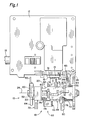
- Fig. 1 is a partial front elevational view of an ink-jet printer illustrating an ink-jet printhead and a service station constructed in accordance with the present invention.
- Fig. 2 is an exploded perspective view of both the black cartridge service station and the color cartridge service station of Fig. 1.
- Fig. 3 is an enlarged perspective view, shown in cross-section, of the color cartridge service station of Figs. 1 and 2.
- Fig. 4 is an elevational section view of the color cartridge service station of Fig. 3.
- Fig. 5 is a view similar to Fig. 4 with the color cartridge cap urged against a printhead.
- Indicated generally at 10 in Figs. 1 and 2 is a service station for both black cartridge and color cartridge printheads constructed in accordance with the present invention.
Service station 10 is incorporated into an ink-jet printer into which either a color cartridge or black cartridge may be loaded for color or black ink printing. The printer includes acarriage 12 which is shown in the view of Fig. 1 having a black cartridge 14 (shown partially broken away) mounted thereon.Cartridge 14 includes aprinthead 15 having nozzles (not shown) formed therein for firing ink in the cartridge therefrom. Carriage 12 is bidirectionally moveable along aguide rod 16 which substantially spans the width of the printer. The carriage is shown in its rightmost position, as viewed in Fig. 1, which placescartridge 14 inservice station 10.Carriage 12 moves to the service station when the printer is not printing or when the printhead needs servicing. On other printers the service station may be located at the leftmost side of the printer. - Although not shown for clarity, the printer includes structure for guiding paper through the printer so that the paper surface is positioned immediately beneath
printhead 15 whencarriage 12 moves leftwardly fromservice station 10. -
Service station 10 includes a color cartridge service station, indicated generally at 18, and a black cartridge service station, indicated generally at 20.Service stations rotatable carrier 22.Carrier 22 is rotatable 180 about anaxis 24. The carrier rotates responsive to a driven gear (not shown) which engages with asprocket 26 oncarrier 22. If a color cartridge, instead ofblack cartridge 14, is mounted oncarriage 12,carrier 22 rotates 180 so thatcolor station 18 is oriented upwardly withblack station 20 assuming the position shown for the color station in Fig. 1. On the other hand, withblack cartridge 14 mounted oncarriage 12,carrier 22 is in the position illustrated in Fig. 1. -
Black station 20 includes a cap indicated generally at 31. The cap includes abasin structure 28, ablack sled 30 and ablack sled cover 32 all of which are received in atray 34 formed incarrier 22. Aspring 36 biases sled 30, as well as sledcover 32 andbasin structure 28 which are mounted on the sled, to the left as viewed in Fig. 1. Tray 34 includes a pair of opposed cam surfaces, 38, 40 upon which cam followers, likecam followers post 46 presents a leftward-facing surface which engages with an anarm 48 oncarriage 12 as the carriage moves to the right. As can be seen in Fig. 1, whencarriage 12 moves leftwardly from the service station,spring 36biases sled 30 to the left.Followers ride surface 40 downwardly thus lowering the sled from the view of Fig. 1. Conversely, as the sled moves toward the service station,arm 48 engagespost 46 thus movingsled 30 to the right and upwardly. Such action urgessled cover 32 againstprinthead 15. - As the black cartridge moves into the station,
printhead 15 traverses the tip of awiper 50 which wipes ink and debris from the printhead surface.Wiper 50 is mounted on afollower bracket 52. The follower bracket includes apost 54 which is received in anopening 56 formed inwiper 50. Arectangular frame 58 surrounds acam 60 mounted oncarrier 22. A pair of downwardly extendingposts carrier 22 in Fig. 1. It can be seen thatbracket 52 is maintained in an upper position bycam 60 whencarrier 22 is in the position illustrated in Fig. 1. When the carrier rotates 180 ° , the bracket moves to a lower position ascam 60 rotates from under the bracket. -
Color station 18 includes a color cap indicated generally at 65. The color cap includes asled cover 66 and a color sled 68 (which is also referred to herein as a base). Aspring 70 biases the sled to the left in Fig. 1.sled cover 66 is mounted onsled 68. When a color cartridge (not shown), rather thanblack cartridge 14, is mounted oncarriage 12,carrier 22 is rotated 180 aboutaxis 24 thus directingsled cover 66 in an upward direction. Whencarrier 22 so rotates,cam 60 inverts and drivesbracket 52 to its lower position. Acolor wiper 72 which is mounted oncarrier 22 is then also directed upwardly. - A cam surface 74 (in Fig. 1), such being similar to
surface 40, is formed oncarrier 22.Cam followers followers surface 40. Anarm 80 extends fromcolor sled 68 in the same fashion that arm 46 extends fromblack sled 30. - With a color cartridge (not shown) mounted on
carriage 12 instead ofblack cartridge 14, movement ofcolor sled 68 relative tocarriage 12 is similar to that previously described forblack sled 30. Ascarriage 12 moves to the right toward the position illustrated in Fig. 1, the color printhead is wiped bywipers 72 the tips of which extend above the tips ofwiper 50, which is in its lower position. Next,arm 48 oncarriage 12 strikes post 80 thereby movingcolor sled 68 upwardly and to the right.Sled cover 66 is thus urged against the color printhead. - Turning now to Figs. 3-5 consideration will be given in more detail to the structure of
cap 65. In the present embodiment of the inventioncolor sled cover 66 is molded from ethylene propylene diene monomer(EPDM) having a hardness of 35 Shore A. The sled cover includes an upper sealing lip 82 (also referred to herein as sealing means) which is formed on an upper surface of a tubular structure ormember 84 having a substantially rectangular cross section, best viewed in Fig. 2. As seen in Figs. 4 and 5,member 84 includes anupper opening 86 which is bounded by the inner perimeter oflip 82, and alower opening 88, also viewable in Fig. 2. -
Tubular member 84 comprises anupper wall 90 and alower wall 92 which are integrally formed. As can be seen in Figs. 4 and 5,wall 90 is slightly thinner thanwall 92. - At the juncture of
walls 90, 92 adiaphragm 94 is joined totubular member 94 about an inner perimeter thereof thus sealing that portion of the tubular member bounded bywall 90 from that portion bounded bywall 92. The portion ofsled cover 66 betweendiaphragm 94 andlip 84 comprises achamber 95, such being also referred to herein as a cavity. - In the present embodiment of the invention, all of
sled cover 66 is integrally molded from EPDM having uniform hardness and flexibility. Becausediaphragm 94 is thinner thantubular member 84, the diaphragm flexes more easily than the tubular member. Similarly, becauseupper wall 90 is thinner thanlower wall 92 there is slightly more flex in the upper wall relative to the lower wall. In the present embodiment of the invention,upper wall 90 is sufficiently flexible so that a person may apply lateral and downward pressure againstupper wall 90 with his or her finger to deform the cap to the extent that the upper wall folds over against the diaphragm.Upper wall 90 is, however, sufficiently rigid that no drooping or sagging of the wall occurs when pressure is not applied thereto. - Considering now
color sled 68, in thepresent embodiment sled 68 is made from nylon 6-10 30% GF. Relative tocolor sled cover 66,sled 68 is substantially rigid. The sled includes a substantially square recessedgroove 96. A substantiallysquare portion 98 of the base extends upwardly interior ofgroove 96.Portion 98 is also referred to herein as a vapor-impervious or vapor-diffusion barrier.sled cover 66 is mounted onsled 68 via an interference fit betweenportion 98 and the lower portion oftubular member 84. Due to the flexibility oflower wall 92 of the cap and the relative dimensions ofsquare portion 98 andlower wall 92, a seal betweensquare portion 98 andlower wall 92 is formed about the circumference of the cap. Adiaphragm deflection chamber 100 is formed betweendiaphragm 94 andsquare portion 98. Avent 102 comprises a bore having an upper opening in communication withchamber 100 and a lower opening in communication with the exterior ofsled 68. The lower opening ofvent 102 is also visible in Fig. 2. -
Sled 68 further includes alug 104 over which one end of spring 70 (in Figs. 1 and 2) is received. The sled further includes a pair of downward extending legs, one of which isleg 106, which act to retain the sled oncarrier 22 while permitting lateral and vertical sled movement as previously described. - In operation,
carriage 12 has a color cartridge (not shown) mounted thereon rather thanblack cartridge 14.Carrier 22 is rotated 180 aboutaxis 24 thus placingopening 86 insled cover 66 immediately beneath the line of travel of the color cartridge printhead. Ascarriage 12 moves to the right toward the position illustrated in Fig. 1,arm 48 strikes post 80 thus movingcolor sled 68 to the right as carriage travel continues. During such movement, the cams, likecams cam surface 74. This action movessled cover 66 toward the color printhead. Ascarriage 12 reaches the position illustrated in Fig. 1,sled cover 66 drives into color printhead 108 (in Fig. 5) beneath anozzle plate 110 bearing the nozzles (not shown) through which the color cartridge ejects ink onto paper in the printer. -
Lip 82 andupper wall 90 are sufficiently flexible to permit sealing against the lower surface ofprinthead 108 as illustrated in Fig. 5 and to accommodate any difference in manufacturing tolerances between the cap and the printhead. Aslip 82 strikes the printhead, the pressure inchamber 95 rises thus causingdiaphragm 94 to deflect downwardly as illustrated in Fig. 5. Such deflection is possible because of the highly flexible nature ofmembrane 94 and becausechamber 100 is vented to atmosphere viavent 102. -
Diaphragm 94 provides an effective liquid barrier betweenchamber 95 and vent 102 thus preventing moisture from cloggingvent 102. Vent 102 also serves, as mentioned above, to vent betweenchamber 100 and atmospheric pressure to permit deflection ofdiaphragm 94 as shown in Fig. 5. Because vapor diffusion throughdiaphragm 94 is possible, it is advantageous and desireable forvent 102 to be substantially elongate and relatively narrow in diameter thus minimizing diffusion fromchamber 100 to atmosphere. So minimizing the diffusion reduces diffusion fromchamber 95 tochamber 100 throughdiaphragm 94 and thereby inhibits ink drying in the nozzles. - It should be appreciated that
diaphragm 94 serves to prevent large pressure differentials betweenchamber 95 and the ambient pressure regardless of the effect tending to cause the pressure differential, e.g., pressure differentials brought about as a result of temperature variations or altitude excursions.Diaphragm 94 flexes upwardly in the event of an effect tending to reduce pressure inchamber 95 relative to ambient pressure, e.g., whencarriage 12 moves leftwardly from a position in Fig. 1 andspring 70 returnscolor sled 68 to its leftward, lower position. Ascup 66 draws away fromprinthead 108, pressure inchamber 95 tends to drop relative to ambient pressure with such a tendency being counteracted by upward flexing ofdiaphragm 94. - Having illustrated and described the principles of our invention in a preferred embodiment thereof, it should be readily apparent to those skilled in the art that the invention can be modified in arrangement and detail without departing from such principles. We claim all modifications coming within the spirit and scope of the accompanying claims.
Claims (9)
Applications Claiming Priority (2)
| Application Number | Priority Date | Filing Date | Title |
|---|---|---|---|
| US07/737,943 US5146243A (en) | 1991-07-29 | 1991-07-29 | Diaphragm cap system for ink-jet printers |
| US737943 | 1991-07-29 |
Publications (3)
| Publication Number | Publication Date |
|---|---|
| EP0526010A2 true EP0526010A2 (en) | 1993-02-03 |
| EP0526010A3 EP0526010A3 (en) | 1993-05-26 |
| EP0526010B1 EP0526010B1 (en) | 1996-10-16 |
Family
ID=24965905
Family Applications (1)
| Application Number | Title | Priority Date | Filing Date |
|---|---|---|---|
| EP92306212A Expired - Lifetime EP0526010B1 (en) | 1991-07-29 | 1992-07-07 | Diaphragm cap system for ink-jet printers |
Country Status (4)
| Country | Link |
|---|---|
| US (1) | US5146243A (en) |
| EP (1) | EP0526010B1 (en) |
| JP (1) | JP3342511B2 (en) |
| DE (1) | DE69214549T2 (en) |
Cited By (1)
| Publication number | Priority date | Publication date | Assignee | Title |
|---|---|---|---|---|
| US6382766B1 (en) * | 2000-04-20 | 2002-05-07 | Samsung Electronics Co., Ltd. | Maintenance apparatus for ink nozzle of image forming apparatus |
Families Citing this family (66)
| Publication number | Priority date | Publication date | Assignee | Title |
|---|---|---|---|---|
| DE59010285D1 (en) * | 1990-01-09 | 1996-05-15 | Eastman Kodak Co | INK PRINTING DEVICE WITH A CLEANING AND SEALING STATION |
| JP3091485B2 (en) * | 1990-01-09 | 2000-09-25 | イーストマン コダック カンパニー | Suction and coating device for sucking ink from the printer head of an ink jet printer and for coating the printer head |
| KR0140505B1 (en) * | 1991-01-31 | 1998-06-01 | 볼프강 마우스, 지그프리트 나스 | Honeycomb body with non-uniform electric heating |
| EP0584960B1 (en) * | 1992-08-26 | 1997-01-02 | Hewlett-Packard Company | Ink-jet printhead cap having suspended lip |
| US5455609A (en) * | 1992-09-30 | 1995-10-03 | Hewlett-Packard Company | Printhead servicing station for printers |
| US5587729A (en) * | 1993-05-11 | 1996-12-24 | Hewlett-Packard Company | Rotatable service station for ink-jet printer |
| DE69417293T2 (en) * | 1993-06-25 | 1999-10-14 | Canon Kk | Ink jet recorder |
| US5563637A (en) * | 1993-10-26 | 1996-10-08 | Lexmark International, Inc. | Maintenance station for ink jet printhead |
| US5612722A (en) * | 1993-10-26 | 1997-03-18 | Lexmark International, Inc. | Ink jet printhead wiper having side surfaces intersecting a top surface at acute angles to form wiping edges and a slat centered in a bottom surface |
| US5572245A (en) * | 1994-03-10 | 1996-11-05 | Hewlett-Packard Company | Protective cover apparatus for an ink-jet pen |
| US5712668A (en) * | 1994-03-25 | 1998-01-27 | Hewlett-Packard Company | Rotary Multi-ridge capping system for inkjet printheads |
| US5742308A (en) * | 1994-03-30 | 1998-04-21 | Hewlett-Packard Company | Ink jet printer cartridge refilling method and apparatus |
| JP3259748B2 (en) * | 1994-03-31 | 2002-02-25 | セイコーエプソン株式会社 | Ink jet recording device |
| US5691755A (en) * | 1994-04-18 | 1997-11-25 | Hewlett-Packard Company | Collapsible ink cartridge |
| US5640182A (en) * | 1994-10-24 | 1997-06-17 | Lexmark International, Inc. | Universal ink-jet printhead maintenance station |
| US5661510A (en) * | 1994-11-22 | 1997-08-26 | Lexmark International, Inc. | Ink-jet cartridge venting |
| US5589865A (en) * | 1994-12-14 | 1996-12-31 | Hewlett-Packard Company | Inkjet page-wide-array printhead cleaning method and apparatus |
| US5635965A (en) * | 1995-01-31 | 1997-06-03 | Hewlett-Packard Company | Wet capping system for inkjet printheads |
| US5583548A (en) * | 1995-03-01 | 1996-12-10 | Hewlett-Packard Company | Bi-directional wiper for ink jet printhead and method of operation |
| US5714991A (en) * | 1995-03-03 | 1998-02-03 | Hewlett-Packard Company | Rotary priming system for inkjet printheads |
| US5801725A (en) * | 1995-05-03 | 1998-09-01 | Encad, Inc. | Slidable wiping and capping service station for ink jet printer |
| US5757395A (en) * | 1995-09-25 | 1998-05-26 | Hewlett-Packard Company | Color capable single-cartridge inkjet service station |
| US5936647A (en) * | 1996-10-31 | 1999-08-10 | Hewlett-Packard Company | Flexible frame onsert capping of inkjet printheads |
| US5956053A (en) * | 1996-10-31 | 1999-09-21 | Hewlett-Packard Company | Dual seal capping system for inkjet printheads |
| JP4022946B2 (en) * | 1996-11-15 | 2007-12-19 | ブラザー工業株式会社 | Capping device |
| JP2878214B2 (en) * | 1996-11-20 | 1999-04-05 | 新潟日本電気株式会社 | Ink jet recording device |
| US6007318A (en) | 1996-12-20 | 1999-12-28 | Z Corporation | Method and apparatus for prototyping a three-dimensional object |
| US7037382B2 (en) | 1996-12-20 | 2006-05-02 | Z Corporation | Three-dimensional printer |
| KR100229508B1 (en) * | 1997-04-22 | 1999-11-15 | 윤종용 | Windows driver making data by sensing an ink cartridge |
| US6082854A (en) | 1998-03-16 | 2000-07-04 | Hewlett-Packard Company | Modular ink-jet hard copy apparatus and methodology |
| US6493937B1 (en) | 1998-03-16 | 2002-12-17 | Hewlett-Packard Company | Method of manufacture for ink-jet hard copy apparatus using a modular approach to ink-jet technology |
| US6406123B1 (en) * | 1998-09-07 | 2002-06-18 | Seiko Epson Corporation | Capping unit for ink jet recording head incorporated in ink jet recording apparatus and method of manufacturing the same |
| US6135585A (en) | 1999-01-08 | 2000-10-24 | Hewlett-Packard Company | Replaceable capping system for inkjet printheads |
| US6520621B1 (en) | 1999-01-08 | 2003-02-18 | Hewlett-Packard Company | Dual wiper scrapers for incompatible inkjet ink wipers |
| US6155667A (en) | 1999-01-08 | 2000-12-05 | Hewlett-Packard Company | Replaceable snout wiper for inkjet cartridges |
| JP2000203040A (en) | 1999-01-08 | 2000-07-25 | Hewlett Packard Co <Hp> | Print head cleaning system |
| US6224186B1 (en) | 1999-01-08 | 2001-05-01 | Hewlett-Packard Company | Replaceable inkjet ink solvent application system |
| US6283576B1 (en) * | 1999-10-29 | 2001-09-04 | Xerox Corporation | Ventable ink jet printhead capping and priming assembly |
| US6406124B1 (en) * | 2000-01-31 | 2002-06-18 | Hewlett-Packard Company | Ganged inkjet printhead capping system |
| US6304728B1 (en) | 2000-03-14 | 2001-10-16 | Concord Camera Corp. | Camera with flash unit disposed in between viewfinder lenses |
| US6378980B1 (en) | 2000-05-18 | 2002-04-30 | Samsung Electronics Co., Ltd. | Printer capable of preventing drying of nozzle and control method thereof |
| US6412905B1 (en) * | 2000-12-21 | 2002-07-02 | Acer Communications And Multimedia | Ink jet cap with vent |
| US6623098B2 (en) | 2001-10-31 | 2003-09-23 | Hewlett-Packard Company, L.P. | Positive stop capping system for inkjet printheads |
| US6609779B2 (en) | 2001-10-31 | 2003-08-26 | Hewlett-Packard Development Company, L.P. | Bellows capping system for inkjet printheads |
| US6742860B2 (en) | 2002-01-18 | 2004-06-01 | Hewlett-Packard Development Company, L.P. | Apparatus and method for capping one or more printheads in a printing device |
| US6962408B2 (en) | 2002-01-30 | 2005-11-08 | Hewlett-Packard Development Company, L.P. | Printing-fluid container |
| US6648460B2 (en) | 2002-01-30 | 2003-11-18 | Hewlett-Packard Development Company, L.P. | High volumetric efficiency ink container vessel |
| US7147310B2 (en) * | 2002-01-30 | 2006-12-12 | Hewlett-Packard Development Company, L.P. | Printing-fluid container |
| US7744202B2 (en) * | 2002-01-30 | 2010-06-29 | Hewlett-Packard Development Company, L.P. | Printing-fluid container |
| US6733106B1 (en) * | 2002-10-24 | 2004-05-11 | Lexmark International, Inc. | Ink jet maintenance station with radial orientation |
| US6877849B2 (en) * | 2003-01-23 | 2005-04-12 | Hewlett-Packard Development Company, L.P. | Printing system with high volumetric ink container vessel |
| US6851787B2 (en) * | 2003-03-06 | 2005-02-08 | Hewlett-Packard Development Company, L.P. | Printer servicing system and method |
| US6932455B2 (en) * | 2003-04-30 | 2005-08-23 | Hewlett-Packard Development Company, L.P. | Printing apparatus and method |
| JP2007503342A (en) | 2003-05-23 | 2007-02-22 | ズィー コーポレイション | Three-dimensional printing apparatus and method |
| US6959985B2 (en) * | 2003-07-31 | 2005-11-01 | Hewlett-Packard Development Company, L.P. | Printing-fluid container |
| US7004564B2 (en) | 2003-07-31 | 2006-02-28 | Hewlett-Packard Development Company, L.P. | Printing-fluid container |
| US7104630B2 (en) * | 2003-07-31 | 2006-09-12 | Hewlett-Packard Development Company, L.P. | Printing-fluid container |
| WO2005097476A2 (en) * | 2004-04-02 | 2005-10-20 | Z Corporation | Methods and apparatus for 3d printing |
| US7387359B2 (en) * | 2004-09-21 | 2008-06-17 | Z Corporation | Apparatus and methods for servicing 3D printers |
| US7311376B2 (en) * | 2004-09-22 | 2007-12-25 | Hewlett-Packard Development Company, L.P. | Imaging device and method |
| US7159964B2 (en) * | 2004-09-30 | 2007-01-09 | Lexmark International, Inc. | Inkjet printer spit cup assembly |
| JP2007268852A (en) * | 2006-03-31 | 2007-10-18 | Brother Ind Ltd | Inkjet recorder and cap |
| KR101537494B1 (en) | 2006-05-26 | 2015-07-16 | 3디 시스템즈 인코오퍼레이티드 | Apparatus and methods for handling materials in a 3-d printer |
| US20100253738A1 (en) * | 2009-04-03 | 2010-10-07 | Keith Jariabka | Carriage-actuated vent system for inkjet print heads |
| US9266336B1 (en) | 2015-04-07 | 2016-02-23 | Xerox Corporation | Ink barrier formed on printhead to prevent air intake |
| JP7087303B2 (en) * | 2017-08-24 | 2022-06-21 | セイコーエプソン株式会社 | Cap device and liquid injection device |
Citations (7)
| Publication number | Priority date | Publication date | Assignee | Title |
|---|---|---|---|---|
| US4432004A (en) * | 1980-11-03 | 1984-02-14 | U.S. Philips Corporation | Device for capping the jet nozzles of an ink jet printing head |
| JPS5945164A (en) * | 1982-09-08 | 1984-03-13 | Seiko Epson Corp | Nozzle cap for ink jet printer |
| JPS6071259A (en) * | 1983-09-29 | 1985-04-23 | Canon Inc | Discharge recovery |
| US4638336A (en) * | 1984-09-05 | 1987-01-20 | Agfa-Gevaert Ag | Cover for vacuum ink printing head |
| US4684963A (en) * | 1984-06-08 | 1987-08-04 | Seiko Epson Kabushiki Kaisha | Nozzle cover assembly for an ink-on-demand type ink jet printer |
| JPS6485769A (en) * | 1987-09-28 | 1989-03-30 | Toshiba Corp | Recorder |
| US5027134A (en) * | 1989-09-01 | 1991-06-25 | Hewlett-Packard Company | Non-clogging cap and service station for ink-jet printheads |
Family Cites Families (5)
| Publication number | Priority date | Publication date | Assignee | Title |
|---|---|---|---|---|
| AT377726B (en) * | 1981-07-24 | 1985-04-25 | Philips Nv | CASSETTE WITH A COVERING DEVICE AND / OR A DEVICE FOR CLEANING THE NOZZLE SURFACE OF A WRITING HEAD OF AN INK PEN |
| US4511906A (en) * | 1982-10-13 | 1985-04-16 | Sharp Kabushiki Kaisha | Ink liquid reservoir in an ink jet system printer |
| GB2131745B (en) * | 1982-10-14 | 1986-06-25 | Epson Corp | Ink jet head assembly |
| JP2522770B2 (en) * | 1986-08-05 | 1996-08-07 | キヤノン株式会社 | Inkjet device |
| US4853717A (en) * | 1987-10-23 | 1989-08-01 | Hewlett-Packard Company | Service station for ink-jet printer |
-
1991
- 1991-07-29 US US07/737,943 patent/US5146243A/en not_active Expired - Lifetime
-
1992
- 1992-07-07 EP EP92306212A patent/EP0526010B1/en not_active Expired - Lifetime
- 1992-07-07 DE DE69214549T patent/DE69214549T2/en not_active Expired - Fee Related
- 1992-07-22 JP JP21636892A patent/JP3342511B2/en not_active Expired - Fee Related
Patent Citations (7)
| Publication number | Priority date | Publication date | Assignee | Title |
|---|---|---|---|---|
| US4432004A (en) * | 1980-11-03 | 1984-02-14 | U.S. Philips Corporation | Device for capping the jet nozzles of an ink jet printing head |
| JPS5945164A (en) * | 1982-09-08 | 1984-03-13 | Seiko Epson Corp | Nozzle cap for ink jet printer |
| JPS6071259A (en) * | 1983-09-29 | 1985-04-23 | Canon Inc | Discharge recovery |
| US4684963A (en) * | 1984-06-08 | 1987-08-04 | Seiko Epson Kabushiki Kaisha | Nozzle cover assembly for an ink-on-demand type ink jet printer |
| US4638336A (en) * | 1984-09-05 | 1987-01-20 | Agfa-Gevaert Ag | Cover for vacuum ink printing head |
| JPS6485769A (en) * | 1987-09-28 | 1989-03-30 | Toshiba Corp | Recorder |
| US5027134A (en) * | 1989-09-01 | 1991-06-25 | Hewlett-Packard Company | Non-clogging cap and service station for ink-jet printheads |
Non-Patent Citations (3)
| Title |
|---|
| PATENT ABSTRACTS OF JAPAN vol. 008, no. 148 (M-308) <1585> 11 July 1984 & JP 59 045164 A (EPUSON) 13 March 1984 * |
| PATENT ABSTRACTS OF JAPAN vol. 009, no. 213 (M-408) <1936> 30 August 1985 & JP 60 071259 A (CANON) 23 April 1985 * |
| PATENT ABSTRACTS OF JAPAN vol. 013, no. 296 (M-846) <3644> 10 July 1989 & JP 01 085769 A (TOSHIBA CORP.) 30 March 1989 * |
Cited By (1)
| Publication number | Priority date | Publication date | Assignee | Title |
|---|---|---|---|---|
| US6382766B1 (en) * | 2000-04-20 | 2002-05-07 | Samsung Electronics Co., Ltd. | Maintenance apparatus for ink nozzle of image forming apparatus |
Also Published As
| Publication number | Publication date |
|---|---|
| US5146243A (en) | 1992-09-08 |
| EP0526010B1 (en) | 1996-10-16 |
| EP0526010A3 (en) | 1993-05-26 |
| JPH05201007A (en) | 1993-08-10 |
| DE69214549T2 (en) | 1997-03-06 |
| JP3342511B2 (en) | 2002-11-11 |
| DE69214549D1 (en) | 1996-11-21 |
Similar Documents
| Publication | Publication Date | Title |
|---|---|---|
| EP0526010B1 (en) | Diaphragm cap system for ink-jet printers | |
| US5216449A (en) | Rounded capillary vent system for ink-jet printers | |
| US5027134A (en) | Non-clogging cap and service station for ink-jet printheads | |
| EP0313204B1 (en) | Service station for ink-jet printer | |
| EP0671273B1 (en) | Protective capping apparatus for an ink jet pen | |
| US5210550A (en) | Maintenance station for ink jet printers | |
| EP0901905B1 (en) | Capping device for ink jet recording head | |
| JP3710013B2 (en) | Colorable single cartridge inkjet service station | |
| EP0622201B1 (en) | Priming apparatus for ink jet printer | |
| AU724168B2 (en) | Cap for service station for ink-jet printheads | |
| US6174041B1 (en) | Modular printhead service station with self-contained motorized components | |
| US6074037A (en) | Print head capping device | |
| US6616265B2 (en) | Suction cap for ink-jet recording apparatus | |
| US7806506B2 (en) | Droplet ejecting device having cap that seals nozzles | |
| US5627573A (en) | Maintenance device in an ink jet printing apparatus | |
| US20020060711A1 (en) | Ink jet printer provided with maintenance system | |
| US4571600A (en) | Nozzle blockage preventing unit in an ink jet system printer | |
| US7806507B2 (en) | Liquid ejection apparatus, capping device, and installation device for liquid absorber | |
| US5627574A (en) | Maintenance device in an ink jet printing apparatus | |
| US6817695B1 (en) | Printhead capping assembly | |
| US7021741B2 (en) | Printhead cap assembly for an ink jet printer | |
| US6709087B2 (en) | Printing device | |
| JP3765361B2 (en) | Inkjet recording device | |
| US6588874B2 (en) | Airtight elastic cap of ink-jet recording head, storage container, and ink-jet recording apparatus | |
| KR940002059A (en) | Inkjet printer |
Legal Events
| Date | Code | Title | Description |
|---|---|---|---|
| PUAI | Public reference made under article 153(3) epc to a published international application that has entered the european phase |
Free format text: ORIGINAL CODE: 0009012 |
|
| AK | Designated contracting states |
Kind code of ref document: A2 Designated state(s): DE FR GB IT |
|
| PUAL | Search report despatched |
Free format text: ORIGINAL CODE: 0009013 |
|
| RIN1 | Information on inventor provided before grant (corrected) |
Inventor name: WARD, JEFFERSON P Inventor name: HARMON, J.P. Inventor name: ENGLISH, KRIS M. |
|
| AK | Designated contracting states |
Kind code of ref document: A3 Designated state(s): DE FR GB IT |
|
| 17P | Request for examination filed |
Effective date: 19931103 |
|
| 17Q | First examination report despatched |
Effective date: 19950210 |
|
| GRAH | Despatch of communication of intention to grant a patent |
Free format text: ORIGINAL CODE: EPIDOS IGRA |
|
| ITF | It: translation for a ep patent filed |
Owner name: SOCIETA' ITALIANA BREVETTI S.P.A. |
|
| GRAA | (expected) grant |
Free format text: ORIGINAL CODE: 0009210 |
|
| AK | Designated contracting states |
Kind code of ref document: B1 Designated state(s): DE FR GB IT |
|
| REF | Corresponds to: |
Ref document number: 69214549 Country of ref document: DE Date of ref document: 19961121 |
|
| ET | Fr: translation filed | ||
| PLBE | No opposition filed within time limit |
Free format text: ORIGINAL CODE: 0009261 |
|
| STAA | Information on the status of an ep patent application or granted ep patent |
Free format text: STATUS: NO OPPOSITION FILED WITHIN TIME LIMIT |
|
| 26N | No opposition filed | ||
| REG | Reference to a national code |
Ref country code: GB Ref legal event code: 732E |
|
| REG | Reference to a national code |
Ref country code: FR Ref legal event code: TP |
|
| REG | Reference to a national code |
Ref country code: GB Ref legal event code: IF02 |
|
| PGFP | Annual fee paid to national office [announced via postgrant information from national office to epo] |
Ref country code: FR Payment date: 20050718 Year of fee payment: 14 |
|
| REG | Reference to a national code |
Ref country code: FR Ref legal event code: ST Effective date: 20070330 |
|
| PGFP | Annual fee paid to national office [announced via postgrant information from national office to epo] |
Ref country code: DE Payment date: 20070831 Year of fee payment: 16 |
|
| PGFP | Annual fee paid to national office [announced via postgrant information from national office to epo] |
Ref country code: IT Payment date: 20070730 Year of fee payment: 16 |
|
| PG25 | Lapsed in a contracting state [announced via postgrant information from national office to epo] |
Ref country code: FR Free format text: LAPSE BECAUSE OF NON-PAYMENT OF DUE FEES Effective date: 20060731 |
|
| PG25 | Lapsed in a contracting state [announced via postgrant information from national office to epo] |
Ref country code: DE Free format text: LAPSE BECAUSE OF NON-PAYMENT OF DUE FEES Effective date: 20090203 |
|
| PG25 | Lapsed in a contracting state [announced via postgrant information from national office to epo] |
Ref country code: IT Free format text: LAPSE BECAUSE OF NON-PAYMENT OF DUE FEES Effective date: 20080707 |
|
| PGFP | Annual fee paid to national office [announced via postgrant information from national office to epo] |
Ref country code: GB Payment date: 20110725 Year of fee payment: 20 |
|
| REG | Reference to a national code |
Ref country code: GB Ref legal event code: 732E Free format text: REGISTERED BETWEEN 20120329 AND 20120404 |
|
| REG | Reference to a national code |
Ref country code: GB Ref legal event code: PE20 Expiry date: 20120706 |
|
| PG25 | Lapsed in a contracting state [announced via postgrant information from national office to epo] |
Ref country code: GB Free format text: LAPSE BECAUSE OF EXPIRATION OF PROTECTION Effective date: 20120706 |