EP0525577A2 - Carrier device - Google Patents
Carrier device Download PDFInfo
- Publication number
- EP0525577A2 EP0525577A2 EP92112402A EP92112402A EP0525577A2 EP 0525577 A2 EP0525577 A2 EP 0525577A2 EP 92112402 A EP92112402 A EP 92112402A EP 92112402 A EP92112402 A EP 92112402A EP 0525577 A2 EP0525577 A2 EP 0525577A2
- Authority
- EP
- European Patent Office
- Prior art keywords
- reaction vessel
- carrier device
- container
- set forth
- holder
- Prior art date
- Legal status (The legal status is an assumption and is not a legal conclusion. Google has not performed a legal analysis and makes no representation as to the accuracy of the status listed.)
- Granted
Links
Images

Classifications
-
- B—PERFORMING OPERATIONS; TRANSPORTING
- B01—PHYSICAL OR CHEMICAL PROCESSES OR APPARATUS IN GENERAL
- B01L—CHEMICAL OR PHYSICAL LABORATORY APPARATUS FOR GENERAL USE
- B01L3/00—Containers or dishes for laboratory use, e.g. laboratory glassware; Droppers
- B01L3/50—Containers for the purpose of retaining a material to be analysed, e.g. test tubes
- B01L3/502—Containers for the purpose of retaining a material to be analysed, e.g. test tubes with fluid transport, e.g. in multi-compartment structures
-
- B—PERFORMING OPERATIONS; TRANSPORTING
- B01—PHYSICAL OR CHEMICAL PROCESSES OR APPARATUS IN GENERAL
- B01F—MIXING, e.g. DISSOLVING, EMULSIFYING OR DISPERSING
- B01F31/00—Mixers with shaking, oscillating, or vibrating mechanisms
- B01F31/20—Mixing the contents of independent containers, e.g. test tubes
- B01F31/201—Holders therefor
-
- G—PHYSICS
- G01—MEASURING; TESTING
- G01N—INVESTIGATING OR ANALYSING MATERIALS BY DETERMINING THEIR CHEMICAL OR PHYSICAL PROPERTIES
- G01N35/00—Automatic analysis not limited to methods or materials provided for in any single one of groups G01N1/00 - G01N33/00; Handling materials therefor
- G01N35/02—Automatic analysis not limited to methods or materials provided for in any single one of groups G01N1/00 - G01N33/00; Handling materials therefor using a plurality of sample containers moved by a conveyor system past one or more treatment or analysis stations
-
- G—PHYSICS
- G01—MEASURING; TESTING
- G01N—INVESTIGATING OR ANALYSING MATERIALS BY DETERMINING THEIR CHEMICAL OR PHYSICAL PROPERTIES
- G01N35/00—Automatic analysis not limited to methods or materials provided for in any single one of groups G01N1/00 - G01N33/00; Handling materials therefor
- G01N2035/00465—Separating and mixing arrangements
- G01N2035/00524—Mixing by agitating sample carrier
-
- G—PHYSICS
- G01—MEASURING; TESTING
- G01N—INVESTIGATING OR ANALYSING MATERIALS BY DETERMINING THEIR CHEMICAL OR PHYSICAL PROPERTIES
- G01N35/00—Automatic analysis not limited to methods or materials provided for in any single one of groups G01N1/00 - G01N33/00; Handling materials therefor
- G01N35/02—Automatic analysis not limited to methods or materials provided for in any single one of groups G01N1/00 - G01N33/00; Handling materials therefor using a plurality of sample containers moved by a conveyor system past one or more treatment or analysis stations
- G01N35/04—Details of the conveyor system
- G01N2035/0401—Sample carriers, cuvettes or reaction vessels
- G01N2035/0429—Sample carriers adapted for special purposes
- G01N2035/0436—Sample carriers adapted for special purposes with pre-packaged reagents, i.e. test-packs
-
- Y—GENERAL TAGGING OF NEW TECHNOLOGICAL DEVELOPMENTS; GENERAL TAGGING OF CROSS-SECTIONAL TECHNOLOGIES SPANNING OVER SEVERAL SECTIONS OF THE IPC; TECHNICAL SUBJECTS COVERED BY FORMER USPC CROSS-REFERENCE ART COLLECTIONS [XRACs] AND DIGESTS
- Y10—TECHNICAL SUBJECTS COVERED BY FORMER USPC
- Y10S—TECHNICAL SUBJECTS COVERED BY FORMER USPC CROSS-REFERENCE ART COLLECTIONS [XRACs] AND DIGESTS
- Y10S436/00—Chemistry: analytical and immunological testing
- Y10S436/807—Apparatus included in process claim, e.g. physical support structures
- Y10S436/808—Automated or kit
Definitions
- This invention relates to a carrier device for holding samples which are to be analyzed in a manner which facilitates their combination with analysis reagents and apparatus for transferring the results for determination by further instrumentation.
- the device of this invention which facilitates the analysis of samples in a reaction vessel.
- the device comprises a top member having an end portion, a support for the top member, a transparent container having analysis reagents contained therein and having a header containing an instruction code formed on the header, a sample holder being removably mounted on the top member adjacent the header, and a reaction vessel holder mounted by the top member in the end portion, whereby the sample may be positioned in the reaction vessel for reaction and thereafter transferred to the transparent container for analysis.
- the device of the invention is mounted to permit the sample to be nutated.
- the reaction vessel itself comprises an inner container having a longitudinal axis and which contains a first reagent and an outer container coaxially positioned about the upper portion of the inner container, the outer container having a second reagent. It is desirable that the transparent container be slidably removeable from the top member to facilitate its use and transfer for further analysis.
- the apparatus of this invention maintains three units together, i.e., the sample, the reagent for analysis and the ultimate processed sample in a separate container. This facilitates processing samples and maintains all the units necessary for analysis together during the analysis time interval.
- Multiple sample cups may be simply clipped on to the carrier for use with different sample input and separate incubation is permitted by the structure of the carrier for material within the reaction vessel.
- the carrier is seen to contain a hollow, molded housing 50 defined by a pair of sidewalls 52, a top plate 58, and a base support 60.
- a drive bar 140 is positioned in the lower portion between the sidewalls and secured to the base support as by glueing. This bar has receptacles 61 to facilitate its receiving driving or positioning pins for positioning the bar 140 and hence the carrier.
- the housing may be formed of polysulfone or any other suitable engineering plastic which is rigid, strong and chemically inert.
- a partition 54 which cooperates with the top 58 to accommodate the top frame of an analytical pack 62 of an analytical pack 64 which may be the same and preferably is the same as the aca@ pack used in the aca@ Automatic Clinical Analyzer sold by E. I. du Pont de Nemours and Company, Wilmington, Delaware, U.S.A.
- the aca@ pack has identifying indicia 66 on the top which may be read by appropriate sensors to indicate the particular test being run and includes a hollow septum 68 with an orifice 70 which may be used to introduce materials into the a plastic pack 72. Since the aca@ pack is well known it will not be described further.
- the partition 54 and top 58 cooperate to define an orifice 56 adapted to accommodate the top member of the aca@ pack 62 so it may be inserted into the carrier with the lower side pack 72, which is formed of plastic material.
- the side pack is to slide in between the two walls 52.
- the top of the carrier 50 also includes an elongated cup-like member 76 which is adapted to receive a removable sample reservoir 78 containing a reservoir 80.
- the sample reservoir 78 is held in the position within the opening 76 by appropriate molded grips 82.
- a fitting feature 84 may be provided for the sample holder 78 to control access to the opening.
- the end of the top member 58 may have an orifice 86 with downwardly extending flanges 88 adapted to hold a reaction vessel holder 90.
- the flanges 88 are concave on the inside to define a socket which cooperates with the bulbous top on a reaction vessel holder 90 in a ball and socket joint manner.
- the lower portion of the reaction vessel holder 90 may be shaped as to have an inverted cavity or receptacle 92 at the upper end of which is a bore 94 adapted to receive a pin from a nutating drive member.
- the reaction vessel holder 90 may be the reaction vessel itself although the use of the holder is preferred for its long term stability and reliability. If the reaction vessel 90, as a tube holder, is adapted to receive a reaction vessel 100, the vessel has at the upper portion thereof a concentric chamber 102 for holding reaction reagents that typically may be used, for example, in an immunoassay process.
- the reaction vessel holder 90 is nutated by an automatic apparatus 104.
- any suitable drive apparatus may be used that provides two directions of linear motion and one direction of rotary motion, that described in copending application Serial No. , filed , (IP-0905) is one that has been used successfully. This drive apparatus provides a bidirectional motion as depicted by the line 106 (Fig.
- the drive apparatus is powered by a single bidirectional drive motor 110 which provides rotational motion to the drive apparatus 104.
- the automatic apparatus engages the reaction vessel holder 90 by elevating a mixing cylinder on which a pin is positioned contiguous the periphery at a point off the elongated axis of the mixing cylinder. In other words the pin engages the bottom end of the mixing vessel 90 in a position which is eccentric to the axis which mounts the mixing cylinder. The apparatus then spins the cylinder moving the engaged end of the vessel into an orbit.
- the contents of the reaction vessel holder 90 will swirl or nutate thus mixing them. Reversal of the drive which spins the mixing cylinder 110 stops the orbiting of the vessel and lowers the cylinder thus disengaging the cylinder from the reaction vessel holder 90.
- the carrier device just described has many advantages and it permits in effect the combination of three different functions into a single device. Firstly, sample cups from various analysis devices holding the sample may be snapped into place in the upper portion of the device. Secondly, a reaction tube containing reagents for the analysis of samples may be inserted into a carrier tube which may be inserted into and processed separately from the carrier unit. Thirdly, the completed reacted sample with reagents may be introduced into a separate unit which is slidably removeable from the carrier for subsequent processing and analysis is desired in other machines.
Abstract
Description
- Cross Reference to Related Patent Applications
- This invention discloses materials which is disclosed and/or claimed in a patent application entitled Vortex Mixer Drive, Serial No.
- filed (IP-0801) and also an application entitled Multilinear Automatic Apparatus for Processing Immunoassays, Serial No.
- filed (IP-0905).
- This invention relates to a carrier device for holding samples which are to be analyzed in a manner which facilitates their combination with analysis reagents and apparatus for transferring the results for determination by further instrumentation.
- In the analytical field it is often necessary to process samples of reagents for analysis by combining them with various reagents, support particles and the like. Following such analysis, it is then necessary to transfer the processed sample held in a reaction device back to a device which facilitates processing the results. This is particularly true when the interim processing of a sample involves repeated steps that typically required immunoassay techniques. These include reaction time and wash cycles all involving the use or other particles to facilitate the chemical reactions. In a case of immunoassays, it is necessary to vortex the contents of a reaction vessel to maintain the particles suspended so that the reaction may go to completion. Such analysis may also present difficulties inasmuch as the samples may come from different units and all require mounting on the processing carrier. A further problem arises due to the combination of the samples and reagents during the processing. It is difficult to keep track of the proper sample to make sure it receives the processing needed and does not become mixed up with other samples so that the integrity of the analysis is lost.
- Many of these problems are solved by the device of this invention which facilitates the analysis of samples in a reaction vessel. The device comprises a top member having an end portion, a support for the top member, a transparent container having analysis reagents contained therein and having a header containing an instruction code formed on the header, a sample holder being removably mounted on the top member adjacent the header, and a reaction vessel holder mounted by the top member in the end portion, whereby the sample may be positioned in the reaction vessel for reaction and thereafter transferred to the transparent container for analysis.
- In a particularly preferred embodiment, the device of the invention is mounted to permit the sample to be nutated. The reaction vessel itself comprises an inner container having a longitudinal axis and which contains a first reagent and an outer container coaxially positioned about the upper portion of the inner container, the outer container having a second reagent. It is desirable that the transparent container be slidably removeable from the top member to facilitate its use and transfer for further analysis.
- The apparatus of this invention maintains three units together, i.e., the sample, the reagent for analysis and the ultimate processed sample in a separate container. This facilitates processing samples and maintains all the units necessary for analysis together during the analysis time interval.
- Multiple sample cups may be simply clipped on to the carrier for use with different sample input and separate incubation is permitted by the structure of the carrier for material within the reaction vessel.
- This invention will be more clearly understood when considered in conjunction with the accompanying drawings in which like reference numerals refer to like components in each of the drawings, in which:
- Figure 1 is an exploded view of the carrier device constructed in accordance with this invention;
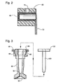
- Figure 2 is a section taken through the stopper of a container along the lines 2-2 of Figure 1; and
- Figure 3 is a section taken along the lines 3-3 of Figure 1 particularly depicting the construction of the sample holder.
- There may be seen in Figures 1, 2, and 3, exploded sectional views of one of the carriers constructed in accordance with this invention. The carrier is seen to contain a hollow, molded
housing 50 defined by a pair ofsidewalls 52, atop plate 58, and abase support 60. Adrive bar 140 is positioned in the lower portion between the sidewalls and secured to the base support as by glueing. This bar hasreceptacles 61 to facilitate its receiving driving or positioning pins for positioning thebar 140 and hence the carrier. The housing may be formed of polysulfone or any other suitable engineering plastic which is rigid, strong and chemically inert. Attached to the front sidewall (in the drawing) is apartition 54 which cooperates with thetop 58 to accommodate the top frame of ananalytical pack 62 of an analytical pack 64 which may be the same and preferably is the same as the aca@ pack used in the aca@ Automatic Clinical Analyzer sold by E. I. du Pont de Nemours and Company, Wilmington, Delaware, U.S.A. The aca@ pack has identifyingindicia 66 on the top which may be read by appropriate sensors to indicate the particular test being run and includes ahollow septum 68 with anorifice 70 which may be used to introduce materials into the aplastic pack 72. Since the aca@ pack is well known it will not be described further. In any event, thepartition 54 andtop 58 cooperate to define anorifice 56 adapted to accommodate the top member of the aca@ pack 62 so it may be inserted into the carrier with thelower side pack 72, which is formed of plastic material. The side pack is to slide in between the twowalls 52. The top of thecarrier 50 also includes an elongated cup-like member 76 which is adapted to receive aremovable sample reservoir 78 containing areservoir 80. Thesample reservoir 78 is held in the position within the opening 76 by appropriate moldedgrips 82. Afitting feature 84 may be provided for thesample holder 78 to control access to the opening. - To complete the
carrier 50, the end of thetop member 58 may have anorifice 86 with downwardly extendingflanges 88 adapted to hold areaction vessel holder 90. Theflanges 88 are concave on the inside to define a socket which cooperates with the bulbous top on areaction vessel holder 90 in a ball and socket joint manner. The lower portion of thereaction vessel holder 90 may be shaped as to have an inverted cavity orreceptacle 92 at the upper end of which is abore 94 adapted to receive a pin from a nutating drive member. - In an alternative embodiment of this invention, the
reaction vessel holder 90 may be the reaction vessel itself although the use of the holder is preferred for its long term stability and reliability. If thereaction vessel 90, as a tube holder, is adapted to receive areaction vessel 100, the vessel has at the upper portion thereof aconcentric chamber 102 for holding reaction reagents that typically may be used, for example, in an immunoassay process. Thereaction vessel holder 90 is nutated by anautomatic apparatus 104. Although any suitable drive apparatus may be used that provides two directions of linear motion and one direction of rotary motion, that described in copending application Serial No. , filed , (IP-0905) is one that has been used successfully. This drive apparatus provides a bidirectional motion as depicted by the line 106 (Fig. 1) as well as rotational motion as depicted by theline 108 to thereaction vessel holder 90. The drive apparatus is powered by a singlebidirectional drive motor 110 which provides rotational motion to thedrive apparatus 104. The automatic apparatus engages thereaction vessel holder 90 by elevating a mixing cylinder on which a pin is positioned contiguous the periphery at a point off the elongated axis of the mixing cylinder. In other words the pin engages the bottom end of themixing vessel 90 in a position which is eccentric to the axis which mounts the mixing cylinder. The apparatus then spins the cylinder moving the engaged end of the vessel into an orbit. If the vessel is managed so that it is free in two rotational directions of freedom, then the contents of thereaction vessel holder 90 will swirl or nutate thus mixing them. Reversal of the drive which spins the mixingcylinder 110 stops the orbiting of the vessel and lowers the cylinder thus disengaging the cylinder from thereaction vessel holder 90. - The carrier device just described has many advantages and it permits in effect the combination of three different functions into a single device. Firstly, sample cups from various analysis devices holding the sample may be snapped into place in the upper portion of the device. Secondly, a reaction tube containing reagents for the analysis of samples may be inserted into a carrier tube which may be inserted into and processed separately from the carrier unit. Thirdly, the completed reacted sample with reagents may be introduced into a separate unit which is slidably removeable from the carrier for subsequent processing and analysis is desired in other machines.
Claims (8)
Applications Claiming Priority (2)
| Application Number | Priority Date | Filing Date | Title |
|---|---|---|---|
| US07/736,155 US5254315A (en) | 1991-07-26 | 1991-07-26 | Carrier device |
| US736155 | 1991-07-26 |
Publications (3)
| Publication Number | Publication Date |
|---|---|
| EP0525577A2 true EP0525577A2 (en) | 1993-02-03 |
| EP0525577A3 EP0525577A3 (en) | 1993-03-31 |
| EP0525577B1 EP0525577B1 (en) | 1996-03-20 |
Family
ID=24958723
Family Applications (1)
| Application Number | Title | Priority Date | Filing Date |
|---|---|---|---|
| EP92112402A Expired - Lifetime EP0525577B1 (en) | 1991-07-26 | 1992-07-20 | Carrier device |
Country Status (5)
| Country | Link |
|---|---|
| US (1) | US5254315A (en) |
| EP (1) | EP0525577B1 (en) |
| JP (1) | JPH05249123A (en) |
| CA (1) | CA2074395A1 (en) |
| DE (1) | DE69209181T2 (en) |
Cited By (7)
| Publication number | Priority date | Publication date | Assignee | Title |
|---|---|---|---|---|
| EP1614474A2 (en) * | 1998-05-01 | 2006-01-11 | Gen-Probe Incorporated | Incubator for automatic analyser |
| EP1681569A3 (en) * | 2003-07-07 | 2006-08-02 | Abbott Laboratories | Assay testing diagnostic analyzer |
| US7794659B2 (en) | 2005-03-10 | 2010-09-14 | Gen-Probe Incorporated | Signal measuring system having a movable signal measuring device |
| US8192992B2 (en) | 1998-05-01 | 2012-06-05 | Gen-Probe Incorporated | System and method for incubating the contents of a reaction receptacle |
| US8718948B2 (en) | 2011-02-24 | 2014-05-06 | Gen-Probe Incorporated | Systems and methods for distinguishing optical signals of different modulation frequencies in an optical signal detector |
| US9046507B2 (en) | 2010-07-29 | 2015-06-02 | Gen-Probe Incorporated | Method, system and apparatus for incorporating capacitive proximity sensing in an automated fluid transfer procedure |
| US10191072B2 (en) | 2005-05-04 | 2019-01-29 | Abbott Laboratories | Reagent and sample handling device for automatic testing system |
Families Citing this family (12)
| Publication number | Priority date | Publication date | Assignee | Title |
|---|---|---|---|---|
| US5945071A (en) * | 1998-04-10 | 1999-08-31 | Abbott Laboratories | Carrier for cuvettes |
| US5948691A (en) * | 1998-04-10 | 1999-09-07 | Abbott Laboratories | Carrier and method of use |
| US6096205A (en) | 1998-05-13 | 2000-08-01 | The Regents Of The University Of California | Hand portable thin-layer chromatography system |
| US7288195B2 (en) * | 1999-05-28 | 2007-10-30 | Bio/Data Corporation | Method and apparatus for directly sampling a fluid for microfiltration |
| US6398956B1 (en) | 1999-05-28 | 2002-06-04 | Bio/Data Corporation | Method and apparatus for directly sampling a fluid for microfiltration |
| US6588625B2 (en) * | 2001-04-24 | 2003-07-08 | Abbott Laboratories | Sample handling system |
| US7682833B2 (en) | 2003-09-10 | 2010-03-23 | Abbott Point Of Care Inc. | Immunoassay device with improved sample closure |
| US7723099B2 (en) * | 2003-09-10 | 2010-05-25 | Abbott Point Of Care Inc. | Immunoassay device with immuno-reference electrode |
| WO2011075663A1 (en) | 2009-12-18 | 2011-06-23 | Abbott Point Of Care Inc. | Integrated hinged cartridge housings for sample analysis |
| JP5678248B2 (en) * | 2010-12-21 | 2015-02-25 | メディカテック株式会社 | Test tube stirring device |
| FR3000803B1 (en) * | 2013-01-04 | 2018-05-25 | Immunodiagnostic Systems France | ANALYSIS ASSEMBLY FOR ANALYSIS APPARATUS |
| CN114585486A (en) * | 2019-08-30 | 2022-06-03 | 普罗蒂菲有限责任公司 | Detergent-free simultaneous omics sample preparation method using novel sachet design |
Citations (8)
| Publication number | Priority date | Publication date | Assignee | Title |
|---|---|---|---|---|
| US4004883A (en) * | 1975-07-11 | 1977-01-25 | G. D. Searle & Co. | Sensing, leveling and mixing apparatus |
| US4058367A (en) * | 1976-05-19 | 1977-11-15 | Gilford Instrument Laboratories Inc. | Automatic asynchronous fluid processing apparatus |
| FR2350393A1 (en) * | 1976-05-03 | 1977-12-02 | Mc Donnell Douglas Corp | MACHINE AND METHOD FOR READING CARDS CONTAINING MEDICAL SAMPLES |
| US4066412A (en) * | 1966-04-26 | 1978-01-03 | E. I. Du Pont De Nemours And Company | Automatic clinical analyzer |
| EP0204109A2 (en) * | 1985-06-03 | 1986-12-10 | Becton Dickinson and Company | A self-contained reagent package device for an assay |
| US4980293A (en) * | 1988-09-02 | 1990-12-25 | Multi-Technology Inc. | Dispensing reagents in a specimen well |
| EP0435481A2 (en) * | 1989-12-22 | 1991-07-03 | Anagen (U.K.) Limited | Apparatus and method for selective agitation of reaction components |
| US5104231A (en) * | 1991-07-26 | 1992-04-14 | E. I. Du Pont De Nemours And Company | Vortex mixer drive |
Family Cites Families (11)
| Publication number | Priority date | Publication date | Assignee | Title |
|---|---|---|---|---|
| USRE29725E (en) * | 1966-04-26 | 1978-08-08 | E. I. Du Pont De Nemours And Company | Analytical test pack and process for analysis |
| FR2142746B1 (en) * | 1971-06-24 | 1973-06-29 | Hoffmann La Roche | |
| US4119407A (en) * | 1976-03-08 | 1978-10-10 | Bio-Dynamics, Inc. | Cuvette with reagent release means |
| US4198484A (en) * | 1978-07-26 | 1980-04-15 | Abbott Laboratories | Cuvette ampule for use with automatic analyzer apparatus |
| US4397725A (en) * | 1980-12-15 | 1983-08-09 | Transidyne General Corp. | Apparatus for measuring electrochemical activity |
| US4647541A (en) * | 1982-10-07 | 1987-03-03 | Helena Laboratories Corporation | Method for performing an occult blood test |
| US4791060A (en) * | 1983-11-07 | 1988-12-13 | Allelix Inc. | Device for performing qualitative enzyme immunoassays |
| US5000923A (en) * | 1985-10-31 | 1991-03-19 | Bio/Data Corporation | Apparatus for receiving a test specimen and reagent |
| US4865813A (en) * | 1986-07-07 | 1989-09-12 | Leon Luis P | Disposable analytical device |
| US4970053A (en) * | 1986-07-11 | 1990-11-13 | Beckman Instruments, Inc. | Reagent cartridge |
| US4806316A (en) * | 1987-03-17 | 1989-02-21 | Becton, Dickinson And Company | Disposable device for use in chemical, immunochemical and microorganism analysis |
-
1991
- 1991-07-26 US US07/736,155 patent/US5254315A/en not_active Expired - Fee Related
-
1992
- 1992-07-20 EP EP92112402A patent/EP0525577B1/en not_active Expired - Lifetime
- 1992-07-20 DE DE69209181T patent/DE69209181T2/en not_active Expired - Fee Related
- 1992-07-22 CA CA002074395A patent/CA2074395A1/en not_active Abandoned
- 1992-07-24 JP JP4197933A patent/JPH05249123A/en active Pending
Patent Citations (8)
| Publication number | Priority date | Publication date | Assignee | Title |
|---|---|---|---|---|
| US4066412A (en) * | 1966-04-26 | 1978-01-03 | E. I. Du Pont De Nemours And Company | Automatic clinical analyzer |
| US4004883A (en) * | 1975-07-11 | 1977-01-25 | G. D. Searle & Co. | Sensing, leveling and mixing apparatus |
| FR2350393A1 (en) * | 1976-05-03 | 1977-12-02 | Mc Donnell Douglas Corp | MACHINE AND METHOD FOR READING CARDS CONTAINING MEDICAL SAMPLES |
| US4058367A (en) * | 1976-05-19 | 1977-11-15 | Gilford Instrument Laboratories Inc. | Automatic asynchronous fluid processing apparatus |
| EP0204109A2 (en) * | 1985-06-03 | 1986-12-10 | Becton Dickinson and Company | A self-contained reagent package device for an assay |
| US4980293A (en) * | 1988-09-02 | 1990-12-25 | Multi-Technology Inc. | Dispensing reagents in a specimen well |
| EP0435481A2 (en) * | 1989-12-22 | 1991-07-03 | Anagen (U.K.) Limited | Apparatus and method for selective agitation of reaction components |
| US5104231A (en) * | 1991-07-26 | 1992-04-14 | E. I. Du Pont De Nemours And Company | Vortex mixer drive |
Cited By (36)
| Publication number | Priority date | Publication date | Assignee | Title |
|---|---|---|---|---|
| US8709814B2 (en) | 1998-05-01 | 2014-04-29 | Gen-Probe Incorporated | Method for incubating the contents of a receptacle |
| EP1614474A2 (en) * | 1998-05-01 | 2006-01-11 | Gen-Probe Incorporated | Incubator for automatic analyser |
| US8546110B2 (en) | 1998-05-01 | 2013-10-01 | Gen-Probe Incorporated | Method for detecting the presence of a nucleic acid in a sample |
| US7666602B2 (en) | 1998-05-01 | 2010-02-23 | Gen-Probe Incorporated | Method for agitating the fluid contents of a container |
| US7666681B2 (en) | 1998-05-01 | 2010-02-23 | Gen-Probe Incorporated | Method for agitating the fluid contents of a container |
| US9598723B2 (en) | 1998-05-01 | 2017-03-21 | Gen-Probe Incorporated | Automated analyzer for performing a nucleic acid-based assay |
| US9150908B2 (en) | 1998-05-01 | 2015-10-06 | Gen-Probe Incorporated | Method for detecting the presence of a nucleic acid in a sample |
| US8883455B2 (en) | 1998-05-01 | 2014-11-11 | Gen-Probe Incorporated | Method for detecting the presence of a nucleic acid in a sample |
| US8569020B2 (en) | 1998-05-01 | 2013-10-29 | Gen-Probe Incorporated | Method for simultaneously performing multiple amplification reactions |
| EP1614474A3 (en) * | 1998-05-01 | 2006-02-08 | Gen-Probe Incorporated | Incubator for automatic analyser |
| US8137620B2 (en) | 1998-05-01 | 2012-03-20 | Gen-Probe Incorporated | Temperature-controlled incubator having an arcuate closure panel |
| US8012419B2 (en) | 1998-05-01 | 2011-09-06 | Gen-Probe Incorporated | Temperature-controlled incubator having rotatable door |
| US8192992B2 (en) | 1998-05-01 | 2012-06-05 | Gen-Probe Incorporated | System and method for incubating the contents of a reaction receptacle |
| US8221682B2 (en) | 1998-05-01 | 2012-07-17 | Gen-Probe Incorporated | System for incubating the contents of a reaction receptacle |
| US8309358B2 (en) | 1998-05-01 | 2012-11-13 | Gen-Probe Incorporated | Method for introducing a fluid into a reaction receptacle contained within a temperature-controlled environment |
| US8318500B2 (en) | 1998-05-01 | 2012-11-27 | Gen-Probe, Incorporated | Method for agitating the contents of a reaction receptacle within a temperature-controlled environment |
| US8337753B2 (en) | 1998-05-01 | 2012-12-25 | Gen-Probe Incorporated | Temperature-controlled incubator having a receptacle mixing mechanism |
| US8569019B2 (en) | 1998-05-01 | 2013-10-29 | Gen-Probe Incorporated | Method for performing an assay with a nucleic acid present in a specimen |
| EP1681569A3 (en) * | 2003-07-07 | 2006-08-02 | Abbott Laboratories | Assay testing diagnostic analyzer |
| US8501461B2 (en) | 2005-03-10 | 2013-08-06 | Gen-Probe Incorporated | System for performing multi-formatted assays |
| US7897337B2 (en) | 2005-03-10 | 2011-03-01 | Gen-Probe Incorporated | Method for performing multi-formatted assays |
| US8008066B2 (en) | 2005-03-10 | 2011-08-30 | Gen-Probe Incorporated | System for performing multi-formatted assays |
| US8615368B2 (en) | 2005-03-10 | 2013-12-24 | Gen-Probe Incorporated | Method for determining the amount of an analyte in a sample |
| US8663922B2 (en) | 2005-03-10 | 2014-03-04 | Gen-Probe Incorporated | Systems and methods for detecting multiple optical signals |
| US7964413B2 (en) | 2005-03-10 | 2011-06-21 | Gen-Probe Incorporated | Method for continuous mode processing of multiple reaction receptacles in a real-time amplification assay |
| US10006862B2 (en) | 2005-03-10 | 2018-06-26 | Gen-Probe Incorporated | Continuous process for performing multiple nucleic acid amplification assays |
| US7932081B2 (en) | 2005-03-10 | 2011-04-26 | Gen-Probe Incorporated | Signal measuring system for conducting real-time amplification assays |
| US9726607B2 (en) | 2005-03-10 | 2017-08-08 | Gen-Probe Incorporated | Systems and methods for detecting multiple optical signals |
| US8349564B2 (en) | 2005-03-10 | 2013-01-08 | Gen-Probe Incorporated | Method for continuous mode processing of the contents of multiple reaction receptacles in a real-time amplification assay |
| US9372156B2 (en) | 2005-03-10 | 2016-06-21 | Gen-Probe Incorporated | System for processing contents of a receptacle to detect an optical signal emitted by the contents |
| US7794659B2 (en) | 2005-03-10 | 2010-09-14 | Gen-Probe Incorporated | Signal measuring system having a movable signal measuring device |
| US10191072B2 (en) | 2005-05-04 | 2019-01-29 | Abbott Laboratories | Reagent and sample handling device for automatic testing system |
| US9046507B2 (en) | 2010-07-29 | 2015-06-02 | Gen-Probe Incorporated | Method, system and apparatus for incorporating capacitive proximity sensing in an automated fluid transfer procedure |
| US9915613B2 (en) | 2011-02-24 | 2018-03-13 | Gen-Probe Incorporated | Systems and methods for distinguishing optical signals of different modulation frequencies in an optical signal detector |
| US8718948B2 (en) | 2011-02-24 | 2014-05-06 | Gen-Probe Incorporated | Systems and methods for distinguishing optical signals of different modulation frequencies in an optical signal detector |
| US10641707B2 (en) | 2011-02-24 | 2020-05-05 | Gen-Probe Incorporated | Systems and methods for distinguishing optical signals of different modulation frequencies in an optical signal detector |
Also Published As
| Publication number | Publication date |
|---|---|
| DE69209181T2 (en) | 1996-07-25 |
| EP0525577B1 (en) | 1996-03-20 |
| US5254315A (en) | 1993-10-19 |
| CA2074395A1 (en) | 1993-01-27 |
| DE69209181D1 (en) | 1996-04-25 |
| EP0525577A3 (en) | 1993-03-31 |
| JPH05249123A (en) | 1993-09-28 |
Similar Documents
| Publication | Publication Date | Title |
|---|---|---|
| US5254315A (en) | Carrier device | |
| EP0597017B1 (en) | Multi-linear automatic apparatus for processing immunoassays | |
| AU644830B2 (en) | Selective component agitation apparatus and method | |
| EP0416285B1 (en) | Apparatus and method for causing vortices in a test tube | |
| US5104231A (en) | Vortex mixer drive | |
| US5272092A (en) | Method for analyzing a reaction solution | |
| JP3031545B2 (en) | General purpose analyzer for clinical analysis | |
| US5215376A (en) | Method for causing vortices in a test tube | |
| US20020132353A1 (en) | Turntable type liquid reagent stirring apparatus and turntable type liquid reagent stirring/fractionally pouring apparatus using said stirring apparatus | |
| EP1465728B1 (en) | Stackable aliquot vessel array | |
| EP0355823A2 (en) | Method and apparatus for effecting the automatic analytical testing of samples | |
| US6808304B2 (en) | Method for mixing liquid samples using a linear oscillation stroke | |
| JP2006133223A (en) | Rack for analyzer and analyzer having such rack | |
| JPH0445073B2 (en) | ||
| US4227815A (en) | Magnetic stirrer for sample container of photometric analyzer | |
| KR20070026299A (en) | Hematological analyzer on whole blood with stirring device | |
| EP1850136A1 (en) | Shaker device for analyzer apparatus and analyzer comprising such a device | |
| EP0652806B1 (en) | Sample segment | |
| EP0349591B1 (en) | Method for rapid mixing of small volumes for enhancing biological reactions | |
| FI885798A0 (en) | BLANDNINGSANORDNING FOER ANALYSREAGENS FOER UTFOERANDE AV EFTER VARANDRA FOELJANDE ANALYTISKA REAKTIONER. | |
| JP3179581B2 (en) | Stirring device and device provided with the same |
Legal Events
| Date | Code | Title | Description |
|---|---|---|---|
| PUAI | Public reference made under article 153(3) epc to a published international application that has entered the european phase |
Free format text: ORIGINAL CODE: 0009012 |
|
| AK | Designated contracting states |
Kind code of ref document: A2 Designated state(s): DE FR IT |
|
| PUAL | Search report despatched |
Free format text: ORIGINAL CODE: 0009013 |
|
| AK | Designated contracting states |
Kind code of ref document: A3 Designated state(s): DE FR IT |
|
| 17P | Request for examination filed |
Effective date: 19930916 |
|
| 17Q | First examination report despatched |
Effective date: 19940912 |
|
| GRAH | Despatch of communication of intention to grant a patent |
Free format text: ORIGINAL CODE: EPIDOS IGRA |
|
| GRAA | (expected) grant |
Free format text: ORIGINAL CODE: 0009210 |
|
| AK | Designated contracting states |
Kind code of ref document: B1 Designated state(s): DE FR IT |
|
| REF | Corresponds to: |
Ref document number: 69209181 Country of ref document: DE Date of ref document: 19960425 |
|
| ET | Fr: translation filed | ||
| ITF | It: translation for a ep patent filed |
Owner name: ING. C. GREGORJ S.P.A. |
|
| PLBE | No opposition filed within time limit |
Free format text: ORIGINAL CODE: 0009261 |
|
| STAA | Information on the status of an ep patent application or granted ep patent |
Free format text: STATUS: NO OPPOSITION FILED WITHIN TIME LIMIT |
|
| 26N | No opposition filed | ||
| PGFP | Annual fee paid to national office [announced via postgrant information from national office to epo] |
Ref country code: FR Payment date: 19980618 Year of fee payment: 7 |
|
| PGFP | Annual fee paid to national office [announced via postgrant information from national office to epo] |
Ref country code: DE Payment date: 19980625 Year of fee payment: 7 |
|
| PG25 | Lapsed in a contracting state [announced via postgrant information from national office to epo] |
Ref country code: FR Free format text: THE PATENT HAS BEEN ANNULLED BY A DECISION OF A NATIONAL AUTHORITY Effective date: 19990731 |
|
| REG | Reference to a national code |
Ref country code: FR Ref legal event code: TP |
|
| PG25 | Lapsed in a contracting state [announced via postgrant information from national office to epo] |
Ref country code: DE Free format text: LAPSE BECAUSE OF NON-PAYMENT OF DUE FEES Effective date: 20000503 |
|
| REG | Reference to a national code |
Ref country code: FR Ref legal event code: ST |
|
| REG | Reference to a national code |
Ref country code: FR Ref legal event code: TP Ref country code: FR Ref legal event code: CD |
|
| PG25 | Lapsed in a contracting state [announced via postgrant information from national office to epo] |
Ref country code: IT Free format text: LAPSE BECAUSE OF NON-PAYMENT OF DUE FEES Effective date: 20050720 |