EP0523901A1 - Battery with integral condition tester - Google Patents
Battery with integral condition tester Download PDFInfo
- Publication number
- EP0523901A1 EP0523901A1 EP19920306254 EP92306254A EP0523901A1 EP 0523901 A1 EP0523901 A1 EP 0523901A1 EP 19920306254 EP19920306254 EP 19920306254 EP 92306254 A EP92306254 A EP 92306254A EP 0523901 A1 EP0523901 A1 EP 0523901A1
- Authority
- EP
- European Patent Office
- Prior art keywords
- cell
- combination
- terminal
- label
- indicator
- Prior art date
- Legal status (The legal status is an assumption and is not a legal conclusion. Google has not performed a legal analysis and makes no representation as to the accuracy of the status listed.)
- Granted
Links
Images
Classifications
-
- G—PHYSICS
- G01—MEASURING; TESTING
- G01D—MEASURING NOT SPECIALLY ADAPTED FOR A SPECIFIC VARIABLE; ARRANGEMENTS FOR MEASURING TWO OR MORE VARIABLES NOT COVERED IN A SINGLE OTHER SUBCLASS; TARIFF METERING APPARATUS; MEASURING OR TESTING NOT OTHERWISE PROVIDED FOR
- G01D7/00—Indicating measured values
- G01D7/005—Indication of measured value by colour change
-
- H—ELECTRICITY
- H01—ELECTRIC ELEMENTS
- H01M—PROCESSES OR MEANS, e.g. BATTERIES, FOR THE DIRECT CONVERSION OF CHEMICAL ENERGY INTO ELECTRICAL ENERGY
- H01M6/00—Primary cells; Manufacture thereof
- H01M6/50—Methods or arrangements for servicing or maintenance, e.g. for maintaining operating temperature
- H01M6/5044—Cells or batteries structurally combined with cell condition indicating means
- H01M6/505—Cells combined with indicating means for external visualization of the condition, e.g. by change of colour or of light intensity
-
- H—ELECTRICITY
- H01—ELECTRIC ELEMENTS
- H01M—PROCESSES OR MEANS, e.g. BATTERIES, FOR THE DIRECT CONVERSION OF CHEMICAL ENERGY INTO ELECTRICAL ENERGY
- H01M10/00—Secondary cells; Manufacture thereof
- H01M10/42—Methods or arrangements for servicing or maintenance of secondary cells or secondary half-cells
- H01M10/48—Accumulators combined with arrangements for measuring, testing or indicating the condition of cells, e.g. the level or density of the electrolyte
- H01M10/488—Cells or batteries combined with indicating means for external visualization of the condition, e.g. by change of colour or of light density
-
- Y—GENERAL TAGGING OF NEW TECHNOLOGICAL DEVELOPMENTS; GENERAL TAGGING OF CROSS-SECTIONAL TECHNOLOGIES SPANNING OVER SEVERAL SECTIONS OF THE IPC; TECHNICAL SUBJECTS COVERED BY FORMER USPC CROSS-REFERENCE ART COLLECTIONS [XRACs] AND DIGESTS
- Y02—TECHNOLOGIES OR APPLICATIONS FOR MITIGATION OR ADAPTATION AGAINST CLIMATE CHANGE
- Y02E—REDUCTION OF GREENHOUSE GAS [GHG] EMISSIONS, RELATED TO ENERGY GENERATION, TRANSMISSION OR DISTRIBUTION
- Y02E60/00—Enabling technologies; Technologies with a potential or indirect contribution to GHG emissions mitigation
- Y02E60/10—Energy storage using batteries
Definitions
- This invention relates to an improved combination of an electrochemical cell and an integrally related battery condition indicator.
- Electrical primary cells which include a means for visually indicating the condition or state of charge of the cell are known.
- an indicator apparatus is disclosed in U.S. Pat. No. 1,497,388 which is positioned at a location so that the current in the cell passes through the indicator.
- the indicator is a paper which is impregnated with a chemical that changes color depending upon the strength of the current passing through the chemical impregnated paper. Wires or electrodes must therefore be attached to opposite sides of the impregnated paper to provide a current flow through that paper.
- Disadvantages of this invention are that the lead wires can be easily dislodged, the indicating device can be readily tampered with, and the loose wires interfere with insertion of the cell into a device. Further, the chemical that is impregnated in the paper can be effected by environmental conditions and rendered unreliable.
- a cell exhaustion indicator consisting of a relatively thin layer of a material which-changes appearance on contact with the cell electrolyte.
- the material is positioned between a consumable metal anodic cell container and a transparent wrapper for the cell.
- small holes are created which provide openings through which the electrolyte reaches and soaks through the insulating material to come into contact with an indicating layer.
- a reaction takes place which leaves a white contrasting reaction product.
- This invention would not work for cells which do not consume the container during discharge, such as alkaline zinc/manganese dioxide cells or lithium cells.
- a battery capacity and activation indicating structure includes a piece of absorbent material impregnated with a pH sensitive dye. The material is dried and then positioned in openings in the battery can with a transparent window being provided so that the impregnated material can be viewed. As the charge of the battery is depleted, the ph of the charge producing compound changes thereby causing the impregnated material to change colors. This would not operate in a cell which does not have an appreciable pH change during discharge such as an alkaline manganese dioxide cell or a lithium cell.
- the indicator consists of perforated copper or copper alloy sheet which is made visible from the outside of the cell by a suitable transparent window through the side of the cell.
- the copper sheet becomes coated with a film of zinc giving the copper sheet a gray color.
- the zinc of this film oxidizes and the original coloration of the copper sheet becomes visible.
- Disadvantages of this invention include the fact that the assembly is complicated and the fact that it only can indicate one condition of the battery dependent on the depth that the indicator is embedded in the electrode.
- Chevet U.S. Pat. No. 4,048,388, discloses an indicator consisting of an enclosed substance in the interior of the cell which can be viewed from outside of the battery. This substance is such that it changes color when it comes in contact with the electrolyte. The electrolyte comes in contact with the indicating substance only after the container in which the indicating substance has been placed has been consumed by the charge generating chemical reaction. Hence, the indication will occur only after the charge in the battery has been substantially depleted.
- Bertolino U.S. patent No. 4,497,881 discloses that observation of one of the active materials in the call can provide an indication of the condition of the battery provided that the active material undergoes a continuous color change throughout the normal lifetime of the battery.
- a disadvantage of this invention is that it only works for batteries having active materials which undergo a color change upon discharge. Further, it is undesirable to have any elements penetrating the battery casing or cover, such as the viewing window, which can be a leakage pathway.
- the present invention relates to a cylindrical electrochemical cell comprising a cylindrical container a portion of which functions as a first external terminal, a cover, a second external terminal, and an integrally related state of charge indicator positioned externally both to said cell top and said container.
- the state of charge indicator has two electrical contacts and a display means connected therebetween. A first contact is unconnected to either external terminal and a second contact is connected to the other external terminal.
- a switch means is located on one end of the cell and permits electrical connection of the first contact to one of the external terminals to visually indicate the condition of the battery by the display means.
- the indicator is so designed that no part thereof is positioned where it could interfere with insertion of the battery in a device such as would be the case if wires or tabs were associated therewith for connecting terminals at one or both ends of a cell, and the addition of chemicals in order to operate is not required.
- condition indicator is integrally related to the cell label and the switch means is located on one of the ends of the cell. In a second embodiment the condition indicator and switch means are located between the cell top and an opposing end cap.
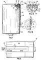
- FIG. 1 shows a cut-away view of an alkaline electrochemical cell 10 having battery condition indicator 12 integrally associated therewith.
- Cell 10 comprises container 20 sealed at its open end by a cell top comprising plastic grommet 30 and metal support 40 being crimped in position as shown.
- Insulating washer 50 is located on top of metal support 40 and prevents contact between said support and negative end terminal 22.
- Negative end terminal 22 is in electrical contact with a metal anode conductor (not shown) which passes through grommet 30 and into an anode filled cavity inside the cell (not shown).
- Battery condition indicator 12 is located externally to the seal, along the outside of the battery container as shown.
- the indicators disclosed in these references generally comprise a substrate having a display means associated therewith.
- the display means generally comprises a conductive layer and a thermochromic material in thermal contact with the conductive layer.
- the conductive layer generally comprises opposite end portions which function as electrical contacts and an intermediate portion connected between the contacts which is designed to have a particular resistance.
- the contacts and the resistive portion can be portions of the same deposit (using silver epoxy, for example) wherein the resistive portion is created by having a lower cross sectional area than the contacts.
- the resistive portion can comprise a deposit of a more resistive material than is used for the contacts.
- the contacts can each comprise a metallic-like deposit that is connected to an end portion of the resistive portion, for example, the resistive portion can be made from a carbonaceous material and the contacts can be made from a silver epoxy.
- indicator 12 is of the type described in the preceding paragraph and comprises a first electrical contact 14 at one end thereof (see FIG. 1a). Contact 14 is normally unconnected to negative terminal 22. However, connection is made to activate the condition indicator by use of a switch means, discussed more fully below.
- a second electrical contact 16 At the opposite end of indicator 12 is a second electrical contact 16 that is mechanically and electrically connected to cell container 20 by label 24 (see FIG. 1b).
- electrical contacts 14 and 16 are part of a conductive deposit wherein the intermediate portion of the deposit between the contacts is more resistive than the contacts. This resistive portion must be electrically insulated from container 20, otherwise indicator 12 would be continuously connected across the terminals of the cell and the cell would rapidly discharge.
- Figs. 1, 1A, and 1B show insulating layer 18 located between indicator 12 and container 20.
- the present invention further comprises a switch means for electrically connecting and disconnecting electrical contact 14 from negative terminal 22.
- a switch means is provided that comprises aperture 19 provided in insulator 18 directly beneath contact 14 (see FIG. 1A). Insulator 18, described more fully below, is an electrical and thermal insulator that normally separates contact 14 from negative terminal 22. However, by pressing label 24 in the area over aperture 19 contact 14 is mechanically and electrically connected to terminal 22 as long as the pressure is maintained. After the battery condition is read from indicator 12 the pressure is released and contact 14 springs away from terminal 22 due the elastic properties of label 24 and the circuit is broken. Thus, insulating layer 18 and hole 19 function as a switch means for the condition indicator.
- Insulating layer 18 also serves to thermally insulate the resistive element from container 20 so that the heat generated in the resistive element during testing can be effectively transferred to the thermochromic indicating material.
- Insulating layer 18 can be made from any insulating material such as polyester, PVC, polyolefins, fiberglass, glass, rubber, polycarbonate, paper, cardboard, and the like formed into a sheet.
- Layer 18 preferably has dimensions which are sufficient to insulate the intermediate portion of the conductive deposit from the cell container. The thickness of layer 18 should be the minimum necessary to permit condition indicator 12 to function properly so that the combined thicknesses of the insulator and condition indicator are kept to a minimum.
- Second electrical contact 16 is shown being held against negative terminal 22 by outer label 24 (see FIG. 1a).
- Outer label 24 can be either a shrink-wrap type, an adhesive-backed wrap-around type or any other type which is conventionally used as a label.
- the graphics of the condition scale are printed on the substrate of indicating means 12 so that the portion of label 24 which covers indicator 12 should be clear in order to reveal the scale.
- the condition scale can be printed on the label and the label positioned so as to align the scale with the underlying position of indicating means 12.
- label 24 is a wrap-around type.
- indicator 12 is an integral part of the label wherein the label functions as a substrate for the thermochromic material and the resistive element.
- the electrical contacts and the resistive element are printed or otherwise deposited on the inside surface of the label.
- the thermochromic layer can be located in a number of places depending on convenience and the type of label used.
- the thermochromic material is placed on the outer portion of the label that is in thermal contact with the resistive element.
- the thermochromic layer and the contacts and resistive element are applied as successive layers to the inside of a clear portion of the label. For example, the thermochromic layer is applied first to a clear portion of the label's inside surface.
- thermochromic layer Over this layer a color graphics layer, which is revealed when the thermochromic layer turns clear, is applied.
- the metallic deposit with the resistive portion coincident with the thermochromic layer and the contacts positioned on opposite ends of and connected to the resistive portion.
- an insulating layer is located over those portions of the metallic deposit desired to be kept insulated from container 20.
- a switch means is made an integral part of the label by providing a hole, similar to hole 19, in the insulating layer and positioned over one of the contacts so that the contact can be pressed against one of the terminals as described above.
- the label, with integrally related condition indicator is applied to the cell container using any conventional manner.
- the substrate used for the condition indicator is preferably made from a material having elastic-type properties.
- the substrate is slightly stretched when pressure is applied over hole 19 to make the measurement and when the pressure is released the substrate returns to its original position and breaks the contact.
- portion 18a of the insulating layer has adhesive on both sides so that the adjacent end of indicator 12 is firmly held in place and prevented from sliding towards opening 19 when pressure is applied during the measurement.
- substrate material include thermoplastics such as polyolefins, polyhalohydrocarbons, and rubber.
- FIG. 2 shows a side view of cell 10 and integrally related condition indicator 12 as described above.
- label 24 is imprinted with a condition scale 26 that is superimposed over condition indicator 12 (shown in ghost outline in FIG. 2) that is fixed to the side of the cell as shown in FIG. 1.
- Pressure is applied to the end of the cell (not shown) over aperture 19 using a finger, pencil eraser, or any other blunt implement. While pressure is maintained a color change appears over condition scale 26. The extent to which the color change appears along scale 26 provides a measurement of the battery condition. Once the applied pressure is released the measurement stops and the thermochromic layer returns to its original color.
- the disconnected contact of the condition indicator is connected to the opposing cell terminal by an integrally related switch means. This is facilitated in the described embodiments having the contact facing the cell terminal. It is also within the scope of the present invention to have the disconnected contact exposed on an external surface of the battery and facing outwardly from the cell terminal. For example, a hole located in the label and condition indicator substrate (if there is one) coincident with the contact would expose said contact (see FIG. 1B). Other embodiments are also possible that would expose the disconnected contact.
- connection of said exposed contact to the cell terminal is achieved by holding a discrete conductive element such as a wire, tab, paper clip or the like so that it touches both the contact and the terminal.
- a discrete conductive element such as a wire, tab, paper clip or the like
- the exposed contact is covered with a piece of adhesive film so that accidental connection can not take place.
- This embodiment may be preferred for batteries that are intended for use in devices where motion of the device can cause pressure to be applied to the side of the battery.
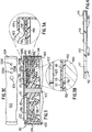
- FIG. 3 shows a cross sectional view through the upper portion of electrochemical cell 110.
- Cell 110 comprises container 120 sealed at its open end by a cell top comprising plastic grommet 130 and metal support 140 crimped in place as shown.
- Insulating washer 150 rests on metal support 140.
- This embodiment differs from the previously described embodiment in that container 120 is crimped inwardly and contacts metal support 140 so that metal support 140 is electrically connected to said container.
- Insulating washer 150 has a centrally located aperture which fits closely over centrally located boss 131 on grommet 130. Additionally, washer 150 has apertures 151 and 152 which are described more fully below.
- Washer 150 can be made of any electrically insulating material such as polyester, PVC, polyolefins, fiberglass, glass, rubber, polycarbonate, paper, cardboard, and the like.
- Battery condition indicator 112 is positioned over washer 150 as shown.
- Indicator 112 operates on the same principle as the indicator described in connection with Figs. 1-2.
- indicator 112 comprises substrate 113, a first electrical contact 114, a second electrical contact 116, and a resistive portion 115 connected between contacts 114 and 116.
- a display means is connected between said contacts and comprises thermochromic layer 118 in thermal contact with resistive portion 115.
- Substrate 113 has aperture 117 located at one end so that anode conductor 123 passes through said aperture and holds condition indicator 112 against grommet 130. With indicator 112 held in this position, electrical contact 116 is positioned over aperture 151 in washer 150. The opposite end of indicator 112 is tightly held between end terminal 122 and washer 150 by label 124. Electrical contact 114 is in mechanical and electrical contact with end terminal 122 as shown in Fig. 3a.
- End terminal 122 is provided with activating aperture 125 and indicating apertures 126a, 126b, and 126c.
- Activating aperture 125 is located over the portion of condition indicator 112 that is superimposed over aperture 151 in washer 150.
- metal support 140 is electrically connected to container 120 as shown, and container 120 is in physical and electrical contact with the positive electrode.
- connection of contact 116 to metal support 140 completes the circuit and current flows through condition indicator 112.
- Resistive element 115 generates resistive heat and that heat is transferred to thermochromic layer 118.
- thermochromic layer 118 By observing thermochromic layer 118 through indicating apertures 126a, 126b, and 126c the condition of the battery is indicated.
- Resistive element 115 is designed to generate heat so that when the battery is in a full state of charge a color indication is observed in thermochromic layer 118 through all three apertures. At some intermediate state of charge a color change is observed in only two of the apertures, and near the end of the useful life of the battery a color change is observed in only one aperture.
- one indicating aperture can be located over the display means when successive layers of thermochromic materials are used. For example three different thermochromic materials having different transition temperatures are layered with the material having the lowest transition temperature on top and the material having the highest transition temperature on the bottom. With each layer having a different "cold color" the observed color depends on how hot the resistive element becomes which in turn depends on the condition of the battery.
- thermochromic layer 118 In order to enhance the color change of thermochromic layer 118 it is desirable to include aperture 152 in washer 150. As shown in FIG. 3 aperture 152 is located beneath the portion of indicator 112 which bears thermochromic layer 118. Thus, an air layer is provided under indicator 112, which air layer acts as a thermal insulator. However, aperture 152 can be omitted if the material used for washer 150 is itself a reasonable thermal insulator.
- condition indicator will depend, of course, on the size and voltage of the associated battery.
- the patents incorporated herein by reference contain disclosure sufficient for one skilled in the art to design and construct a condition indicator suitable for use in the present invention.
- the thermochromic materials disclosed in said patents include liquid crystals and thermochromic inks. Of these, thermochromic inks are preferred because more dramatic color effects ere possible than when liquid crystals are used.
Abstract
Description
- This invention relates to an improved combination of an electrochemical cell and an integrally related battery condition indicator.
- Electrical primary cells which include a means for visually indicating the condition or state of charge of the cell are known. For example, an indicator apparatus is disclosed in U.S. Pat. No. 1,497,388 which is positioned at a location so that the current in the cell passes through the indicator. The indicator is a paper which is impregnated with a chemical that changes color depending upon the strength of the current passing through the chemical impregnated paper. Wires or electrodes must therefore be attached to opposite sides of the impregnated paper to provide a current flow through that paper. Disadvantages of this invention are that the lead wires can be easily dislodged, the indicating device can be readily tampered with, and the loose wires interfere with insertion of the cell into a device. Further, the chemical that is impregnated in the paper can be effected by environmental conditions and rendered unreliable.
- In Reilly, et al., U.S. Pat. No. 2,980,754 issued April 19, 1961, a cell exhaustion indicator is disclosed consisting of a relatively thin layer of a material which-changes appearance on contact with the cell electrolyte. The material is positioned between a consumable metal anodic cell container and a transparent wrapper for the cell. As the anode is consumed producing electricity, small holes are created which provide openings through which the electrolyte reaches and soaks through the insulating material to come into contact with an indicating layer. When the electrolyte makes contact with the indicating layer, a reaction takes place which leaves a white contrasting reaction product. This invention would not work for cells which do not consume the container during discharge, such as alkaline zinc/manganese dioxide cells or lithium cells.
- In Eekma, U.S. Pat. No. 3,514,338 an indicator is added to the casing of a battery with the indicator substance being color changeable in the presence of water. This indicating substance is viewable through a transparent casing portion of the cell. This invention is only capable of indicating that the cell has been activated and is not capable of indicating the relative condition of the battery during usage.
- In Hruden, U.S. Pat. No. 3,563,806, a battery capacity and activation indicating structure includes a piece of absorbent material impregnated with a pH sensitive dye. The material is dried and then positioned in openings in the battery can with a transparent window being provided so that the impregnated material can be viewed. As the charge of the battery is depleted, the ph of the charge producing compound changes thereby causing the impregnated material to change colors. This would not operate in a cell which does not have an appreciable pH change during discharge such as an alkaline manganese dioxide cell or a lithium cell.
- In Eaton, Jr., et al., U.S. Pat. No. 3,773,563 a dye/aluminum mixture is placed in a cylindrical recess drilled in a zinc plate with the recess being sealed to cover the dye/aluminum mixture. As power is provided from the battery, the zinc electrode is dissolved until the end of the recess is eaten away and the dye liberated. The change in color of the electrolyte when the dye is released can be viewed to indicate that the life of the battery has been depleted. Disadvantages of this invention are that it is located inside the cell, which complicates assembly, and it only works with a plate-type electrode.
- In Depoix, U.S. Pat. No. 3,992,228, issued November 16, 1976, the indicator consists of perforated copper or copper alloy sheet which is made visible from the outside of the cell by a suitable transparent window through the side of the cell. When assembled, the copper sheet becomes coated with a film of zinc giving the copper sheet a gray color. During cell discharge, the zinc of this film oxidizes and the original coloration of the copper sheet becomes visible. Disadvantages of this invention include the fact that the assembly is complicated and the fact that it only can indicate one condition of the battery dependent on the depth that the indicator is embedded in the electrode.
- Chevet, U.S. Pat. No. 4,048,388, discloses an indicator consisting of an enclosed substance in the interior of the cell which can be viewed from outside of the battery. This substance is such that it changes color when it comes in contact with the electrolyte. The electrolyte comes in contact with the indicating substance only after the container in which the indicating substance has been placed has been consumed by the charge generating chemical reaction. Hence, the indication will occur only after the charge in the battery has been substantially depleted.
- Finally, Bertolino, U.S. patent No. 4,497,881 discloses that observation of one of the active materials in the call can provide an indication of the condition of the battery provided that the active material undergoes a continuous color change throughout the normal lifetime of the battery. A disadvantage of this invention is that it only works for batteries having active materials which undergo a color change upon discharge. Further, it is undesirable to have any elements penetrating the battery casing or cover, such as the viewing window, which can be a leakage pathway.
- The present invention relates to a cylindrical electrochemical cell comprising a cylindrical container a portion of which functions as a first external terminal, a cover, a second external terminal, and an integrally related state of charge indicator positioned externally both to said cell top and said container. The state of charge indicator has two electrical contacts and a display means connected therebetween. A first contact is unconnected to either external terminal and a second contact is connected to the other external terminal. A switch means is located on one end of the cell and permits electrical connection of the first contact to one of the external terminals to visually indicate the condition of the battery by the display means. The indicator is so designed that no part thereof is positioned where it could interfere with insertion of the battery in a device such as would be the case if wires or tabs were associated therewith for connecting terminals at one or both ends of a cell, and the addition of chemicals in order to operate is not required.
- In one embodiment the condition indicator is integrally related to the cell label and the switch means is located on one of the ends of the cell. In a second embodiment the condition indicator and switch means are located between the cell top and an opposing end cap.
- The features and advantages of the present invention are discussed below in reference to the drawings in which:
- FIG. 1 is cut-away cross-sectional view of an electrochemical cell having a condition indicator made in accordance with the present invention;
- FIG. 1a is an enlarged view of a portion of FIG 1. showing the manner in which electrical connection of one of the contacts of the condition indicator to one of the cell terminals can be made;
- FIG. 1b is an enlarged view of a portion of FIG. 1 showing the manner in which electrical connection of the other contact of the condition indicator to the other cell terminal can be made;
- FIG. 2 shows a side view of a cell having an integrally related condition indicator;
- FIG. 3 shows a cross sectional view through the upper portion of another embodiment of an electrochemical cell having an integrally related condition indicator;
- FIG. 3a is an enlarged view of a portion of FIG 3. showing the manner in which electrical connection of one of the contacts of the condition indicator to one of the cell terminals can be made;
- FIG. 3b is an enlarged view of a portion of FIG. 3 showing the manner in which electrical connection of the other contact of the condition indicator to the other cell terminal can be made;
- FIG. 3c is a partial view of the top of the cell shown in F1G. 3; and
- FIG. 4 is a cross-sectional view through a condition indicator suitable for use in the embodiment shown in FIG. 3.
- Referring now to the drawings, FIG. 1 shows a cut-away view of an alkaline
electrochemical cell 10 havingbattery condition indicator 12 integrally associated therewith.Cell 10 comprisescontainer 20 sealed at its open end by a cell top comprisingplastic grommet 30 andmetal support 40 being crimped in position as shown. Insulatingwasher 50 is located on top ofmetal support 40 and prevents contact between said support andnegative end terminal 22.Negative end terminal 22 is in electrical contact with a metal anode conductor (not shown) which passes throughgrommet 30 and into an anode filled cavity inside the cell (not shown).Battery condition indicator 12 is located externally to the seal, along the outside of the battery container as shown. - In addition to the battery condition indicators described in the references cited above, other indicators are known, such as those disclosed in U.S. patent Nos. 4,835,476, 4,726,661, 4,835,475, 4,702,563, 4,702,564, 4,737,020, 4,006,414, 4,723,656, and U.S. Serial No. 652,165 filed February 7, 1991. All of these indicators are suitable for use in the present invention and the disclosure of each is incorporated herein by reference. With the exception of Serial No. 652,165, the indicators disclosed in these references generally comprise a substrate having a display means associated therewith. The display means generally comprises a conductive layer and a thermochromic material in thermal contact with the conductive layer. The conductive layer generally comprises opposite end portions which function as electrical contacts and an intermediate portion connected between the contacts which is designed to have a particular resistance. The contacts and the resistive portion can be portions of the same deposit (using silver epoxy, for example) wherein the resistive portion is created by having a lower cross sectional area than the contacts. Alternatively, the resistive portion can comprise a deposit of a more resistive material than is used for the contacts. In this latter embodiment the contacts can each comprise a metallic-like deposit that is connected to an end portion of the resistive portion, for example, the resistive portion can be made from a carbonaceous material and the contacts can be made from a silver epoxy. When the contacts are connected to the terminals of a battery a current flows through the conductive layer, which current is proportional to the voltage, and therefore, the state of discharge or condition of the battery. The heat generated in the resistive portion due to i²R heating is transferred to the thermochromic layer and causes a color change therein. Observation of the color change provides a visual indication of the condition of the battery. Serial No. 652,165 differs from the other indicators primarily in the use of multiple resistive portions connected in parallel.
- Referring again to the drawings,
indicator 12 is of the type described in the preceding paragraph and comprises a first electrical contact 14 at one end thereof (see FIG. 1a). Contact 14 is normally unconnected tonegative terminal 22. However, connection is made to activate the condition indicator by use of a switch means, discussed more fully below. At the opposite end ofindicator 12 is a secondelectrical contact 16 that is mechanically and electrically connected tocell container 20 by label 24 (see FIG. 1b). As described above,electrical contacts 14 and 16 are part of a conductive deposit wherein the intermediate portion of the deposit between the contacts is more resistive than the contacts. This resistive portion must be electrically insulated fromcontainer 20, otherwiseindicator 12 would be continuously connected across the terminals of the cell and the cell would rapidly discharge. Figs. 1, 1A, and 1B show insulatinglayer 18 located betweenindicator 12 andcontainer 20. - The present invention further comprises a switch means for electrically connecting and disconnecting electrical contact 14 from
negative terminal 22. A switch means is provided that comprises aperture 19 provided ininsulator 18 directly beneath contact 14 (see FIG. 1A).Insulator 18, described more fully below, is an electrical and thermal insulator that normally separates contact 14 fromnegative terminal 22. However, by pressinglabel 24 in the area over aperture 19 contact 14 is mechanically and electrically connected to terminal 22 as long as the pressure is maintained. After the battery condition is read fromindicator 12 the pressure is released and contact 14 springs away fromterminal 22 due the elastic properties oflabel 24 and the circuit is broken. Thus, insulatinglayer 18 and hole 19 function as a switch means for the condition indicator. Insulatinglayer 18 also serves to thermally insulate the resistive element fromcontainer 20 so that the heat generated in the resistive element during testing can be effectively transferred to the thermochromic indicating material. Insulatinglayer 18 can be made from any insulating material such as polyester, PVC, polyolefins, fiberglass, glass, rubber, polycarbonate, paper, cardboard, and the like formed into a sheet.Layer 18 preferably has dimensions which are sufficient to insulate the intermediate portion of the conductive deposit from the cell container. The thickness oflayer 18 should be the minimum necessary to permitcondition indicator 12 to function properly so that the combined thicknesses of the insulator and condition indicator are kept to a minimum. - Second
electrical contact 16 is shown being held againstnegative terminal 22 by outer label 24 (see FIG. 1a).Outer label 24 can be either a shrink-wrap type, an adhesive-backed wrap-around type or any other type which is conventionally used as a label. In one embodiment the graphics of the condition scale (see, for example, Fig. 2) are printed on the substrate of indicating means 12 so that the portion oflabel 24 which coversindicator 12 should be clear in order to reveal the scale. Alternatively, the condition scale can be printed on the label and the label positioned so as to align the scale with the underlying position of indicatingmeans 12. Yet another embodiment is possible whenlabel 24 is a wrap-around type. Withindicator 12 fixed in position on the outer container wall one edge of the wrap-around label is butted against one edge of the indicator and the other label edge, after wrapping around the container, is butted against the other edge ofindicator 12. In thislatter embodiment indicator 12 and insulatinglayer 18 would have to be held tocell container 20 by an appropriate adhesive. In any of the above described embodiments wherein the label covers indicating means 12 it is preferred that the portion of the label which covers the thermochromic material is either cut away or is raised outwardly so that the label can not act as a heat sink and retard the color change of the thermochromic material. - In yet another embodiment,
indicator 12 is an integral part of the label wherein the label functions as a substrate for the thermochromic material and the resistive element. In this embodiment the electrical contacts and the resistive element are printed or otherwise deposited on the inside surface of the label. The thermochromic layer can be located in a number of places depending on convenience and the type of label used. In one embodiment the thermochromic material is placed on the outer portion of the label that is in thermal contact with the resistive element. In a second embodiment the thermochromic layer and the contacts and resistive element are applied as successive layers to the inside of a clear portion of the label. For example, the thermochromic layer is applied first to a clear portion of the label's inside surface. Over this layer a color graphics layer, which is revealed when the thermochromic layer turns clear, is applied. Next in the layering sequence is the metallic deposit with the resistive portion coincident with the thermochromic layer and the contacts positioned on opposite ends of and connected to the resistive portion. In any of the above embodiments an insulating layer is located over those portions of the metallic deposit desired to be kept insulated fromcontainer 20. A switch means is made an integral part of the label by providing a hole, similar to hole 19, in the insulating layer and positioned over one of the contacts so that the contact can be pressed against one of the terminals as described above. The label, with integrally related condition indicator, is applied to the cell container using any conventional manner. - The substrate used for the condition indicator is preferably made from a material having elastic-type properties. Thus, the substrate is slightly stretched when pressure is applied over hole 19 to make the measurement and when the pressure is released the substrate returns to its original position and breaks the contact. To ensure that the substrate is rigidly held during the measurement it is preferred that portion 18a of the insulating layer has adhesive on both sides so that the adjacent end of
indicator 12 is firmly held in place and prevented from sliding towards opening 19 when pressure is applied during the measurement. Non-limiting examples of substrate material include thermoplastics such as polyolefins, polyhalohydrocarbons, and rubber. - FIG. 2 shows a side view of
cell 10 and integrallyrelated condition indicator 12 as described above. In the embodiment shownlabel 24 is imprinted with acondition scale 26 that is superimposed over condition indicator 12 (shown in ghost outline in FIG. 2) that is fixed to the side of the cell as shown in FIG. 1. Pressure is applied to the end of the cell (not shown) over aperture 19 using a finger, pencil eraser, or any other blunt implement. While pressure is maintained a color change appears overcondition scale 26. The extent to which the color change appears alongscale 26 provides a measurement of the battery condition. Once the applied pressure is released the measurement stops and the thermochromic layer returns to its original color. - In the embodiments discussed thus far the disconnected contact of the condition indicator is connected to the opposing cell terminal by an integrally related switch means. This is facilitated in the described embodiments having the contact facing the cell terminal. It is also within the scope of the present invention to have the disconnected contact exposed on an external surface of the battery and facing outwardly from the cell terminal. For example, a hole located in the label and condition indicator substrate (if there is one) coincident with the contact would expose said contact (see FIG. 1B). Other embodiments are also possible that would expose the disconnected contact. (In any of these embodiments there would not be a hole 19 in insulating
layer 18, rather the insulating layer would extend substantially behind said contact.) Connection of said exposed contact to the cell terminal is achieved by holding a discrete conductive element such as a wire, tab, paper clip or the like so that it touches both the contact and the terminal. When the cell condition is not being tested the exposed contact is covered with a piece of adhesive film so that accidental connection can not take place. This embodiment may be preferred for batteries that are intended for use in devices where motion of the device can cause pressure to be applied to the side of the battery. - A further embodiment of the present invention will now be discussed in reference to Figs. 3, 3a, 3b, 3c, and 4. Fig. 3 shows a cross sectional view through the upper portion of
electrochemical cell 110.Cell 110 comprisescontainer 120 sealed at its open end by a cell top comprisingplastic grommet 130 andmetal support 140 crimped in place as shown. Insulatingwasher 150 rests onmetal support 140. This embodiment differs from the previously described embodiment in thatcontainer 120 is crimped inwardly andcontacts metal support 140 so thatmetal support 140 is electrically connected to said container. Insulatingwasher 150 has a centrally located aperture which fits closely over centrally locatedboss 131 ongrommet 130. Additionally,washer 150 hasapertures Washer 150 can be made of any electrically insulating material such as polyester, PVC, polyolefins, fiberglass, glass, rubber, polycarbonate, paper, cardboard, and the like. -
Battery condition indicator 112 is positioned overwasher 150 as shown.Indicator 112 operates on the same principle as the indicator described in connection with Figs. 1-2. As shown in FIG. 4,indicator 112 comprisessubstrate 113, a firstelectrical contact 114, a secondelectrical contact 116, and aresistive portion 115 connected betweencontacts thermochromic layer 118 in thermal contact withresistive portion 115.Substrate 113 hasaperture 117 located at one end so thatanode conductor 123 passes through said aperture and holdscondition indicator 112 againstgrommet 130. Withindicator 112 held in this position,electrical contact 116 is positioned overaperture 151 inwasher 150. The opposite end ofindicator 112 is tightly held betweenend terminal 122 andwasher 150 bylabel 124.Electrical contact 114 is in mechanical and electrical contact withend terminal 122 as shown in Fig. 3a. -
End terminal 122 is provided with activatingaperture 125 and indicating apertures 126a, 126b, and 126c. Activatingaperture 125 is located over the portion ofcondition indicator 112 that is superimposed overaperture 151 inwasher 150. Thus, when an implement such as a pencil point is inserted through activatingaperture 125 and pressed againstcondition indicator 112 electrical contact is made betweencontact 116 andmetal support 140.Metal support 140 is electrically connected tocontainer 120 as shown, andcontainer 120 is in physical and electrical contact with the positive electrode. Thus, connection ofcontact 116 tometal support 140 completes the circuit and current flows throughcondition indicator 112.Resistive element 115 generates resistive heat and that heat is transferred tothermochromic layer 118. By observingthermochromic layer 118 through indicating apertures 126a, 126b, and 126c the condition of the battery is indicated.Resistive element 115 is designed to generate heat so that when the battery is in a full state of charge a color indication is observed inthermochromic layer 118 through all three apertures. At some intermediate state of charge a color change is observed in only two of the apertures, and near the end of the useful life of the battery a color change is observed in only one aperture. - Alternatively, one indicating aperture can be located over the display means when successive layers of thermochromic materials are used. For example three different thermochromic materials having different transition temperatures are layered with the material having the lowest transition temperature on top and the material having the highest transition temperature on the bottom. With each layer having a different "cold color" the observed color depends on how hot the resistive element becomes which in turn depends on the condition of the battery.
- In order to enhance the color change of
thermochromic layer 118 it is desirable to includeaperture 152 inwasher 150. As shown in FIG. 3aperture 152 is located beneath the portion ofindicator 112 which bearsthermochromic layer 118. Thus, an air layer is provided underindicator 112, which air layer acts as a thermal insulator. However,aperture 152 can be omitted if the material used forwasher 150 is itself a reasonable thermal insulator. - The specific design of the condition indicator will depend, of course, on the size and voltage of the associated battery. The patents incorporated herein by reference contain disclosure sufficient for one skilled in the art to design and construct a condition indicator suitable for use in the present invention. The thermochromic materials disclosed in said patents include liquid crystals and thermochromic inks. Of these, thermochromic inks are preferred because more dramatic color effects ere possible than when liquid crystals are used.
- The specific embodiments described above and shown in the drawings are preferred embodiments. Other embodiments than those referred to specifically above, and other materials than those mentioned, may of course be used, and other electrochemical cells and condition indicating means than those referred to may be utilized in the present invention, without departing from the spirit and scope of the invention as claimed.
Claims (17)
- In combination, an electrochemical cell and a cell condition indicator; said cell comprising a cylindrical container the outside surface of which forms a first external terminal, a cover which seals said container, a second external terminal, means for conducting electricity from the inside of the sealed container to the second terminal, and a label which extends over at least a portion of one of said terminals; said cell condition indicator including a display means, a first electrical contact unconnected to either external terminal, a switch means disposed at one end of said cell for connecting and disconnecting said first contact to one of said external terminals, and a second electrical contact electrically connected to the other external terminal; and at least a portion of said cell condition indicator being positioned between the external surface of said label and one of said terminals; whereupon, closing said switch means connects said first electrical contact to said external terminal to activate the cell condition indicator.
- The combination of claim 1 and wherein the switch means electrically connects said first electrical contact to a portion of the cell container.
- The combination of claim 1 and wherein the switch means electrically connects said first electrical contact to said second external terminal.
- The combination of claim 1 and wherein every part of the cell condition indicator substantially conforms to the shape of that portion of the outer surface of the cell at which said indicator is located.
- The combination of claim 1 wherein said display means is positioned on the inner surface of the label and wherein a transparent portion of said label covers said display means.
- The combination of claim 1 wherein said display means comprises at least one resistive element and a thermochromic material in thermal contact with said element.
- The combination of claim 6 wherein said resistive element is located on a portion of the inside surface of the label and the thermochromic material is positioned on the other side of the label coincident with the position of the resistive element.
- The combination of claim 1, wherein said second terminal comprises a circular metal end cap positioned over the cell cover and said second electrical contact means is permanently connected to said end cap.
- The combination of claim 6, wherein said cell condition indicator is at least partially positioned on a portion of the label that extends along a portion of the container outer wall and along a portion of the second terminal, and further comprising insulating means located between said container and said resistive element.
- The combination of claim 1 wherein said label holds said second electrical contact means in mechanical and electrical contact with said second terminal.
- The combination of claim 1 wherein said condition indicator display means comprises at least one resistive element and a thermochromic material in thermal contact therewith, wherein said thermochromic material comprises a thermochromic ink layer located between the inside surface of said label and said resistive element.
- In combination, an electrochemical cell and a cell condition indicator; said cell comprising a container, at least a portion of the outside surface of which forms a first external terminal; a cover for said cell container including a second external terminal which is electrically isolated from said first external terminal; said condition indicator being positioned at one end of said cell and comprising a first electrically conductive means which is mechanically and electrically fixed to said second terminal, a second electrically conductive means which is adapted for electrical connection to said first external terminal but is normally unconnected thereto, and display means adapted to indicate the condition of said cell upon electrical connection of said second electrically conductive means to said first terminal; wherein said second electrically conductive means is accessible for actuation through an aperture to electrically connect said means to said first terminal.
- The combination of claim 12 wherein said cover further comprises a plastic seal member and a metal support member disposed over said seal member which support member is electrically connected to said first terminal; and said second electrically conductive means is capable of mechanical and electrical connection to said support member.
- The combination of claim 13 wherein said second terminal is a metal end cap disposed over said support member, wherein said display means and second electrically conductive means are located between said end cap and said metal support; and wherein said end cap has an aperture therein positioned over said second electrically conductive means for activating said condition indicator by pressing said second electrically conductive means into contact with said support.
- The combination of claim 14 wherein said end cap has at least one indicating aperture for viewing said display means.
- The combination of claim 12 and further comprising an insulating means, wherein said insulating means is positioned over said support member, and wherein said condition indicator is located on said insulating means.
- The combination of 16 wherein said insulating means has an aperture therein positioned beneath said second electrically conductive means, whereby inserting an instrument through said activating aperture and pressing said second electrically conductive means against said support member causes the display means to indicate the condition of the battery as viewed through the indicating aperture.
Priority Applications (1)
| Application Number | Priority Date | Filing Date | Title |
|---|---|---|---|
| EP99202746A EP0969543A3 (en) | 1991-07-16 | 1992-07-08 | Battery with integral condition tester |
Applications Claiming Priority (2)
| Application Number | Priority Date | Filing Date | Title |
|---|---|---|---|
| US73071291A | 1991-07-16 | 1991-07-16 | |
| US730712 | 1991-07-16 |
Related Child Applications (2)
| Application Number | Title | Priority Date | Filing Date |
|---|---|---|---|
| EP99202746A Division EP0969543A3 (en) | 1991-07-16 | 1992-07-08 | Battery with integral condition tester |
| EP99202746.6 Division-Into | 1999-08-25 |
Publications (3)
| Publication Number | Publication Date |
|---|---|
| EP0523901A1 true EP0523901A1 (en) | 1993-01-20 |
| EP0523901B1 EP0523901B1 (en) | 2000-03-08 |
| EP0523901B2 EP0523901B2 (en) | 2008-06-04 |
Family
ID=24936520
Family Applications (2)
| Application Number | Title | Priority Date | Filing Date |
|---|---|---|---|
| EP92306254A Expired - Lifetime EP0523901B2 (en) | 1991-07-16 | 1992-07-08 | Battery with integral condition tester |
| EP99202746A Withdrawn EP0969543A3 (en) | 1991-07-16 | 1992-07-08 | Battery with integral condition tester |
Family Applications After (1)
| Application Number | Title | Priority Date | Filing Date |
|---|---|---|---|
| EP99202746A Withdrawn EP0969543A3 (en) | 1991-07-16 | 1992-07-08 | Battery with integral condition tester |
Country Status (26)
| Country | Link |
|---|---|
| EP (2) | EP0523901B2 (en) |
| JP (1) | JP2849209B2 (en) |
| KR (1) | KR100257100B1 (en) |
| AT (1) | ATE190429T1 (en) |
| AU (1) | AU659483B2 (en) |
| BR (1) | BR9206269A (en) |
| CA (1) | CA2073901C (en) |
| CZ (1) | CZ286104B6 (en) |
| DE (1) | DE69230739T3 (en) |
| DK (1) | DK0523901T3 (en) |
| EC (1) | ECSP920847A (en) |
| ES (1) | ES2144408T3 (en) |
| FI (1) | FI940208A0 (en) |
| GR (1) | GR3033324T3 (en) |
| HU (1) | HU218128B (en) |
| IE (1) | IE68322B1 (en) |
| IL (1) | IL101986A (en) |
| MX (1) | MX9203672A (en) |
| NO (1) | NO304718B1 (en) |
| PT (1) | PT100650B (en) |
| RO (1) | RO116581B1 (en) |
| RU (1) | RU2124786C1 (en) |
| SG (1) | SG66286A1 (en) |
| TW (1) | TW221528B (en) |
| WO (1) | WO1993002353A1 (en) |
| ZA (1) | ZA924166B (en) |
Cited By (36)
| Publication number | Priority date | Publication date | Assignee | Title |
|---|---|---|---|---|
| EP0495636A2 (en) * | 1991-01-15 | 1992-07-22 | Eveready Battery Company, Inc. | Battery with tester label |
| EP0497617A2 (en) * | 1991-01-31 | 1992-08-05 | Eveready Battery Company, Inc. | Battery voltage tester |
| EP0624914A1 (en) * | 1993-05-03 | 1994-11-17 | Morgan Adhesives Company | Battery with tester label and method for producing it |
| EP0624915A1 (en) * | 1993-05-03 | 1994-11-17 | Morgan Adhesives Company | Method for securing a tester device to a battery and the battery so produced |
| EP0626735A1 (en) * | 1993-05-03 | 1994-11-30 | Eveready Battery Company, Inc. | Battery with tester label and method for producing it |
| GB2282697A (en) * | 1993-09-02 | 1995-04-12 | Duracell Inc | Adhesively securing a battery condition indicator to a battery terminal |
| US5418086A (en) * | 1993-08-09 | 1995-05-23 | Eveready Battery Company, Inc. | Battery with coulometric state of charge indicator |
| US5478665A (en) * | 1994-02-02 | 1995-12-26 | Strategic Electronics | Battery with strength indicator |
| US5491038A (en) * | 1994-08-24 | 1996-02-13 | Duracell Inc. | Contact ring for on-cell battery tester |
| WO1996010274A1 (en) * | 1994-09-29 | 1996-04-04 | Duracell Inc. | Electrochemical cell label with integrated tester |
| US5578390A (en) * | 1994-09-29 | 1996-11-26 | Duracell Inc. | Electrochemical cell label with integrated tester |
| US5593794A (en) * | 1995-01-23 | 1997-01-14 | Duracell Inc. | Moisture barrier composite film of silicon nitride and fluorocarbon polymer and its use with an on-cell tester for an electrochemical cell |
| US5607789A (en) * | 1995-01-23 | 1997-03-04 | Duracell Inc. | Light transparent multilayer moisture barrier for electrochemical cell tester and cell employing same |
| US5614333A (en) * | 1994-09-29 | 1997-03-25 | Duracell Inc. | Electrochemical cell label with integrated tester |
| US5760588A (en) * | 1997-07-25 | 1998-06-02 | Eveready Battery Company, Inc. | Dual rate thermochromic battery tester |
| US5830596A (en) * | 1993-05-03 | 1998-11-03 | Morgan Adhesives, Inc. | Method for producing battery tester label and resulting label and battery assembly |
| US5841285A (en) * | 1997-07-25 | 1998-11-24 | Eveready Battery Company, Inc. | Temperature-compensated thermochromic battery tester |
| WO1999004449A1 (en) * | 1997-07-21 | 1999-01-28 | Duracell Inc. | End cap assembly for an electrochemical cell |
| US5867028A (en) * | 1997-07-25 | 1999-02-02 | Eveready Battery Company, Inc. | Battery tester having sections of different resistivity |
| US6184794B1 (en) | 1993-11-01 | 2001-02-06 | Eveready Battery Company, Inc. | Portable lighting device having externally attached voltage tester |
| USRE39703E1 (en) | 1989-02-08 | 2007-06-26 | Strategic Electronics | Battery with strength indicator |
| WO2013112536A1 (en) * | 2012-01-23 | 2013-08-01 | Avery Dennison Corporation | Electrochemical cell labels and accessories |
| US8575939B2 (en) | 2010-01-07 | 2013-11-05 | Paul JANOUSEK | Apparatuses and methods for determining potential energy stored in an electrochemical cell |
| WO2015116464A1 (en) * | 2014-01-29 | 2015-08-06 | The Gillette Company | Light activated power indicator |
| WO2017040285A1 (en) * | 2015-09-01 | 2017-03-09 | Duracell U.S. Operations, Inc. | Battery including an on-cell indicator |
| US10151802B2 (en) | 2016-11-01 | 2018-12-11 | Duracell U.S. Operations, Inc. | Reusable battery indicator with electrical lock and key |
| US10184988B2 (en) | 2012-12-27 | 2019-01-22 | Duracell U.S. Operations, Inc. | Remote sensing of remaining battery capacity using on-battery circuitry |
| US10297875B2 (en) | 2015-09-01 | 2019-05-21 | Duracell U.S. Operations, Inc. | Battery including an on-cell indicator |
| US10416309B2 (en) | 2013-06-21 | 2019-09-17 | Duracell U.S. Operations, Inc. | Systems and methods for remotely determining a battery characteristic |
| US10483634B2 (en) | 2016-11-01 | 2019-11-19 | Duracell U.S. Operations, Inc. | Positive battery terminal antenna ground plane |
| US10608293B2 (en) | 2016-11-01 | 2020-03-31 | Duracell U.S. Operations, Inc. | Dual sided reusable battery indicator |
| US10818979B2 (en) | 2016-11-01 | 2020-10-27 | Duracell U.S. Operations, Inc. | Single sided reusable battery indicator |
| US10916850B2 (en) | 2013-05-23 | 2021-02-09 | Duracell U.S. Operations, Inc. | Omni-directional antenna for a cylindrical body |
| US10964980B2 (en) | 2014-05-30 | 2021-03-30 | Duracell U.S. Operations, Inc. | Indicator circuit decoupled from a ground plane |
| US11024891B2 (en) | 2016-11-01 | 2021-06-01 | Duracell U.S. Operations, Inc. | Reusable battery indicator with lock and key mechanism |
| US11837754B2 (en) | 2020-12-30 | 2023-12-05 | Duracell U.S. Operations, Inc. | Magnetic battery cell connection mechanism |
Families Citing this family (4)
| Publication number | Priority date | Publication date | Assignee | Title |
|---|---|---|---|---|
| US6946067B2 (en) | 2002-01-04 | 2005-09-20 | Lifescan, Inc. | Method of forming an electrical connection between an electrochemical cell and a meter |
| KR100646537B1 (en) * | 2004-10-20 | 2006-11-23 | 삼성에스디아이 주식회사 | Lithium secondary battery |
| JP7004593B2 (en) * | 2018-03-06 | 2022-01-21 | 大阪瓦斯株式会社 | Battery-powered equipment |
| CN112713346B (en) * | 2020-12-15 | 2022-09-20 | 宁波卓越印务有限公司 | Battery label capable of prompting whether battery is old or new |
Citations (5)
| Publication number | Priority date | Publication date | Assignee | Title |
|---|---|---|---|---|
| US4723656A (en) * | 1987-06-04 | 1988-02-09 | Duracell Inc. | Battery package with battery condition indicator means |
| US4835476A (en) * | 1986-11-28 | 1989-05-30 | Three Tec Davis Inc. | Voltage measuring sheet |
| US5015544A (en) * | 1989-02-08 | 1991-05-14 | Strategic Energy Ltd. | Battery with strength indicator |
| EP0497617A2 (en) * | 1991-01-31 | 1992-08-05 | Eveready Battery Company, Inc. | Battery voltage tester |
| EP0497616A2 (en) * | 1991-01-31 | 1992-08-05 | Eveready Battery Company, Inc. | Electrochromic cell testers |
Family Cites Families (10)
| Publication number | Priority date | Publication date | Assignee | Title |
|---|---|---|---|---|
| US945564A (en) * | 1909-06-10 | 1910-01-04 | Paul Max Marko | Storage battery. |
| US964994A (en) * | 1909-12-14 | 1910-07-19 | Paul Max Marko | Storage-battery indicator |
| US1010377A (en) * | 1910-05-13 | 1911-11-28 | Samuel Johnston | Storage battery. |
| US1497388A (en) * | 1922-11-03 | 1924-06-10 | Edward M Sterling | Method of and apparatus for indicating the electrical condition of a cell |
| US4737020A (en) * | 1985-04-15 | 1988-04-12 | Robert Parker | Method for making battery tester for two sizes of batteries |
| US4835475A (en) * | 1986-11-17 | 1989-05-30 | Niichi Hanakura | Battery tester including a thermochromic material |
| JPH01254879A (en) * | 1988-04-04 | 1989-10-11 | Matsushita Electric Ind Co Ltd | Battery housing case |
| US5059895A (en) * | 1990-04-04 | 1991-10-22 | Eastman Kodak Company | Battery voltmeter |
| US5059795A (en) * | 1990-08-23 | 1991-10-22 | Eastman Kodak Company | Multiple beam radiation image reading apparatus |
| CA2058728C (en) * | 1991-01-15 | 1998-11-10 | Jean W. Bailey | Batteries with tester label |
-
1992
- 1992-04-08 SG SG1996007831A patent/SG66286A1/en unknown
- 1992-05-25 IL IL10198692A patent/IL101986A/en not_active IP Right Cessation
- 1992-06-08 ZA ZA924166A patent/ZA924166B/en unknown
- 1992-06-29 MX MX9203672A patent/MX9203672A/en not_active IP Right Cessation
- 1992-07-01 RO RO94-00064A patent/RO116581B1/en unknown
- 1992-07-01 PT PT100650A patent/PT100650B/en not_active IP Right Cessation
- 1992-07-01 KR KR1019930704106A patent/KR100257100B1/en not_active IP Right Cessation
- 1992-07-01 RU RU94019414/09A patent/RU2124786C1/en not_active IP Right Cessation
- 1992-07-01 AU AU23228/92A patent/AU659483B2/en not_active Ceased
- 1992-07-01 WO PCT/US1992/005558 patent/WO1993002353A1/en active IP Right Grant
- 1992-07-01 BR BR9206269A patent/BR9206269A/en not_active IP Right Cessation
- 1992-07-01 IE IE921723A patent/IE68322B1/en not_active IP Right Cessation
- 1992-07-01 HU HU9303317A patent/HU218128B/en not_active IP Right Cessation
- 1992-07-01 CZ CZ199413A patent/CZ286104B6/en not_active IP Right Cessation
- 1992-07-01 JP JP5502821A patent/JP2849209B2/en not_active Expired - Fee Related
- 1992-07-03 EC EC1992000847A patent/ECSP920847A/en unknown
- 1992-07-08 DK DK92306254T patent/DK0523901T3/en active
- 1992-07-08 AT AT92306254T patent/ATE190429T1/en not_active IP Right Cessation
- 1992-07-08 ES ES92306254T patent/ES2144408T3/en not_active Expired - Lifetime
- 1992-07-08 EP EP92306254A patent/EP0523901B2/en not_active Expired - Lifetime
- 1992-07-08 DE DE69230739T patent/DE69230739T3/en not_active Expired - Lifetime
- 1992-07-08 EP EP99202746A patent/EP0969543A3/en not_active Withdrawn
- 1992-07-15 CA CA002073901A patent/CA2073901C/en not_active Expired - Fee Related
- 1992-08-29 TW TW081106826A patent/TW221528B/zh active
-
1993
- 1993-11-30 NO NO934102A patent/NO304718B1/en unknown
-
1994
- 1994-01-14 FI FI940208A patent/FI940208A0/en unknown
-
2000
- 2000-04-26 GR GR20000401008T patent/GR3033324T3/en not_active IP Right Cessation
Patent Citations (5)
| Publication number | Priority date | Publication date | Assignee | Title |
|---|---|---|---|---|
| US4835476A (en) * | 1986-11-28 | 1989-05-30 | Three Tec Davis Inc. | Voltage measuring sheet |
| US4723656A (en) * | 1987-06-04 | 1988-02-09 | Duracell Inc. | Battery package with battery condition indicator means |
| US5015544A (en) * | 1989-02-08 | 1991-05-14 | Strategic Energy Ltd. | Battery with strength indicator |
| EP0497617A2 (en) * | 1991-01-31 | 1992-08-05 | Eveready Battery Company, Inc. | Battery voltage tester |
| EP0497616A2 (en) * | 1991-01-31 | 1992-08-05 | Eveready Battery Company, Inc. | Electrochromic cell testers |
Cited By (63)
| Publication number | Priority date | Publication date | Assignee | Title |
|---|---|---|---|---|
| USRE39703E1 (en) | 1989-02-08 | 2007-06-26 | Strategic Electronics | Battery with strength indicator |
| EP0495636A2 (en) * | 1991-01-15 | 1992-07-22 | Eveready Battery Company, Inc. | Battery with tester label |
| EP0495636A3 (en) * | 1991-01-15 | 1994-03-23 | Eveready Battery Inc | |
| EP0497617A2 (en) * | 1991-01-31 | 1992-08-05 | Eveready Battery Company, Inc. | Battery voltage tester |
| EP0497617A3 (en) * | 1991-01-31 | 1994-03-30 | Eveready Battery Inc | |
| EP0626735A1 (en) * | 1993-05-03 | 1994-11-30 | Eveready Battery Company, Inc. | Battery with tester label and method for producing it |
| US5604049A (en) * | 1993-05-03 | 1997-02-18 | Morgan Adhesive Company | Battery with tester label and method for producing it |
| US6054234A (en) * | 1993-05-03 | 2000-04-25 | Morgan Adhesives Company | Battery tester label for battery |
| EP0624915A1 (en) * | 1993-05-03 | 1994-11-17 | Morgan Adhesives Company | Method for securing a tester device to a battery and the battery so produced |
| US5830596A (en) * | 1993-05-03 | 1998-11-03 | Morgan Adhesives, Inc. | Method for producing battery tester label and resulting label and battery assembly |
| EP0624914A1 (en) * | 1993-05-03 | 1994-11-17 | Morgan Adhesives Company | Battery with tester label and method for producing it |
| US5626978A (en) * | 1993-05-03 | 1997-05-06 | Morgan Adhesives Company | Method for securing a tester device to a battery and the battery so produced |
| US5538806A (en) * | 1993-05-03 | 1996-07-23 | Morgan Adhesive Company | Battery with tester label and method for producing it |
| US5418086A (en) * | 1993-08-09 | 1995-05-23 | Eveready Battery Company, Inc. | Battery with coulometric state of charge indicator |
| GB2282697B (en) * | 1993-09-02 | 1997-04-30 | Duracell Inc | Battery tester adhesive and system |
| GB2282697A (en) * | 1993-09-02 | 1995-04-12 | Duracell Inc | Adhesively securing a battery condition indicator to a battery terminal |
| US6184794B1 (en) | 1993-11-01 | 2001-02-06 | Eveready Battery Company, Inc. | Portable lighting device having externally attached voltage tester |
| US5478665A (en) * | 1994-02-02 | 1995-12-26 | Strategic Electronics | Battery with strength indicator |
| US5789100A (en) * | 1994-02-02 | 1998-08-04 | Stratetic Electronics, Llc | Battery with strength indicator |
| US5491038A (en) * | 1994-08-24 | 1996-02-13 | Duracell Inc. | Contact ring for on-cell battery tester |
| EP0777917A1 (en) * | 1994-08-24 | 1997-06-11 | Duracell Inc. | Contact ring for on-cell battery tester |
| EP0777917A4 (en) * | 1994-08-24 | 2001-04-11 | Duracell Inc | Contact ring for on-cell battery tester |
| US5607790A (en) * | 1994-09-29 | 1997-03-04 | Duracell Inc. | Electrochemical cell label with integrated tester |
| WO1996010274A1 (en) * | 1994-09-29 | 1996-04-04 | Duracell Inc. | Electrochemical cell label with integrated tester |
| US5614333A (en) * | 1994-09-29 | 1997-03-25 | Duracell Inc. | Electrochemical cell label with integrated tester |
| RU2154879C2 (en) * | 1994-09-29 | 2000-08-20 | Дьюраселл Инк. | Labeled electrochemical cell with built-in tester and label manufacturing process |
| US5612151A (en) * | 1994-09-29 | 1997-03-18 | Duracell Inc. | Electrochemical cell label with integrated tester |
| US5578390A (en) * | 1994-09-29 | 1996-11-26 | Duracell Inc. | Electrochemical cell label with integrated tester |
| US5681666A (en) * | 1995-01-23 | 1997-10-28 | Duracell Inc. | Light transparent multilayer moisture barrier for electrochemical celltester and cell employing same |
| US5925479A (en) * | 1995-01-23 | 1999-07-20 | Duracell, Inc. | Moisture barrier composite film of silicon nitride and fluorocarbon polymer and its use with an on-cell tester for an electrochemical cell |
| US5607789A (en) * | 1995-01-23 | 1997-03-04 | Duracell Inc. | Light transparent multilayer moisture barrier for electrochemical cell tester and cell employing same |
| US5593794A (en) * | 1995-01-23 | 1997-01-14 | Duracell Inc. | Moisture barrier composite film of silicon nitride and fluorocarbon polymer and its use with an on-cell tester for an electrochemical cell |
| EP0879484A1 (en) * | 1996-02-08 | 1998-11-25 | Duracell Inc. | Electrochemical cell label with integrated tester |
| EP0879484A4 (en) * | 1996-02-08 | 2002-07-17 | Duracell Inc | Electrochemical cell label with integrated tester |
| WO1999004449A1 (en) * | 1997-07-21 | 1999-01-28 | Duracell Inc. | End cap assembly for an electrochemical cell |
| US5867028A (en) * | 1997-07-25 | 1999-02-02 | Eveready Battery Company, Inc. | Battery tester having sections of different resistivity |
| US5841285A (en) * | 1997-07-25 | 1998-11-24 | Eveready Battery Company, Inc. | Temperature-compensated thermochromic battery tester |
| US5760588A (en) * | 1997-07-25 | 1998-06-02 | Eveready Battery Company, Inc. | Dual rate thermochromic battery tester |
| US8575939B2 (en) | 2010-01-07 | 2013-11-05 | Paul JANOUSEK | Apparatuses and methods for determining potential energy stored in an electrochemical cell |
| WO2013112536A1 (en) * | 2012-01-23 | 2013-08-01 | Avery Dennison Corporation | Electrochemical cell labels and accessories |
| US10184988B2 (en) | 2012-12-27 | 2019-01-22 | Duracell U.S. Operations, Inc. | Remote sensing of remaining battery capacity using on-battery circuitry |
| US10698032B2 (en) | 2012-12-27 | 2020-06-30 | Duracell U.S. Operations, Inc. | Remote sensing of remaining battery capacity using on-battery circuitry |
| US10916850B2 (en) | 2013-05-23 | 2021-02-09 | Duracell U.S. Operations, Inc. | Omni-directional antenna for a cylindrical body |
| US11740291B2 (en) | 2013-06-21 | 2023-08-29 | Duracell U.S. Operations, Inc. | Systems and methods for remotely determining a battery characteristic |
| US10859705B2 (en) | 2013-06-21 | 2020-12-08 | Duracell U.S. Operations, Inc. | Systems and methods for remotely determining a battery characteristic |
| US11307259B2 (en) | 2013-06-21 | 2022-04-19 | Duracell U.S. Operations, Inc. | Systems and methods for remotely determining a battery characteristic |
| US10416309B2 (en) | 2013-06-21 | 2019-09-17 | Duracell U.S. Operations, Inc. | Systems and methods for remotely determining a battery characteristic |
| US9235044B2 (en) | 2014-01-29 | 2016-01-12 | The Gillette Company | Light activated power indicator |
| WO2015116464A1 (en) * | 2014-01-29 | 2015-08-06 | The Gillette Company | Light activated power indicator |
| US10964980B2 (en) | 2014-05-30 | 2021-03-30 | Duracell U.S. Operations, Inc. | Indicator circuit decoupled from a ground plane |
| WO2017040285A1 (en) * | 2015-09-01 | 2017-03-09 | Duracell U.S. Operations, Inc. | Battery including an on-cell indicator |
| US10297875B2 (en) | 2015-09-01 | 2019-05-21 | Duracell U.S. Operations, Inc. | Battery including an on-cell indicator |
| US10818979B2 (en) | 2016-11-01 | 2020-10-27 | Duracell U.S. Operations, Inc. | Single sided reusable battery indicator |
| US10608293B2 (en) | 2016-11-01 | 2020-03-31 | Duracell U.S. Operations, Inc. | Dual sided reusable battery indicator |
| US10483634B2 (en) | 2016-11-01 | 2019-11-19 | Duracell U.S. Operations, Inc. | Positive battery terminal antenna ground plane |
| US10971769B2 (en) | 2016-11-01 | 2021-04-06 | Duracell U.S. Operations, Inc. | Reusable battery indicator with electrical lock and key |
| US11024891B2 (en) | 2016-11-01 | 2021-06-01 | Duracell U.S. Operations, Inc. | Reusable battery indicator with lock and key mechanism |
| US11024892B2 (en) | 2016-11-01 | 2021-06-01 | Duracell U.S. Operations, Inc. | Dual sided reusable battery indicator |
| US11031686B2 (en) | 2016-11-01 | 2021-06-08 | Duracell U.S. Operations, Inc. | Positive battery terminal antenna ground plane |
| US11664539B2 (en) | 2016-11-01 | 2023-05-30 | Duracell U.S. Operations, Inc. | Dual sided reusable battery indicator |
| US11696942B2 (en) | 2016-11-01 | 2023-07-11 | Duracell U.S. Operations, Inc. | Reusable battery indicator with electrical lock and key |
| US10151802B2 (en) | 2016-11-01 | 2018-12-11 | Duracell U.S. Operations, Inc. | Reusable battery indicator with electrical lock and key |
| US11837754B2 (en) | 2020-12-30 | 2023-12-05 | Duracell U.S. Operations, Inc. | Magnetic battery cell connection mechanism |
Also Published As
Similar Documents
| Publication | Publication Date | Title |
|---|---|---|
| EP0523901B2 (en) | Battery with integral condition tester | |
| US5250905A (en) | Battery with electrochemical tester | |
| EP0450938B1 (en) | Battery having a label comprising a voltmeter | |
| US5223003A (en) | Process for preparing a battery tester label | |
| EP0624914B1 (en) | Battery with tester label and method for producing it | |
| US5478665A (en) | Battery with strength indicator | |
| US5409788A (en) | Method for securing a tester device to a battery and the battery so produced | |
| TW297170B (en) | ||
| CA2058728C (en) | Batteries with tester label | |
| EP0626735B1 (en) | Battery with tester label | |
| EP0848826A4 (en) | Condition tester for a battery |
Legal Events
| Date | Code | Title | Description |
|---|---|---|---|
| PUAI | Public reference made under article 153(3) epc to a published international application that has entered the european phase |
Free format text: ORIGINAL CODE: 0009012 |
|
| AK | Designated contracting states |
Kind code of ref document: A1 Designated state(s): AT BE CH DE DK ES FR GB GR IT LI LU MC NL PT SE |
|
| RBV | Designated contracting states (corrected) |
Designated state(s): AT BE CH DE DK ES FR GB GR IT LI LU NL SE |
|
| RIN1 | Information on inventor provided before grant (corrected) |
Inventor name: MILANESE,ROBERT LOUIS Inventor name: KIERNAN, CHARLES EDMOND Inventor name: EISENSMITH,TERRY CHARLES Inventor name: WANG,CHIH-CHUNG |
|
| 17P | Request for examination filed |
Effective date: 19930618 |
|
| 17Q | First examination report despatched |
Effective date: 19941024 |
|
| GRAH | Despatch of communication of intention to grant a patent |
Free format text: ORIGINAL CODE: EPIDOS IGRA |
|
| GRAH | Despatch of communication of intention to grant a patent |
Free format text: ORIGINAL CODE: EPIDOS IGRA |
|
| GRAH | Despatch of communication of intention to grant a patent |
Free format text: ORIGINAL CODE: EPIDOS IGRA |
|
| GRAG | Despatch of communication of intention to grant |
Free format text: ORIGINAL CODE: EPIDOS AGRA |
|
| GRAG | Despatch of communication of intention to grant |
Free format text: ORIGINAL CODE: EPIDOS AGRA |
|
| GRAH | Despatch of communication of intention to grant a patent |
Free format text: ORIGINAL CODE: EPIDOS IGRA |
|
| GRAA | (expected) grant |
Free format text: ORIGINAL CODE: 0009210 |
|
| AK | Designated contracting states |
Kind code of ref document: B1 Designated state(s): AT BE CH DE DK ES FR GB GR IT LI LU NL SE |
|
| REF | Corresponds to: |
Ref document number: 190429 Country of ref document: AT Date of ref document: 20000315 Kind code of ref document: T |
|
| REG | Reference to a national code |
Ref country code: CH Ref legal event code: NV Representative=s name: A. BRAUN, BRAUN, HERITIER, ESCHMANN AG PATENTANWAE Ref country code: CH Ref legal event code: EP |
|
| REF | Corresponds to: |
Ref document number: 69230739 Country of ref document: DE Date of ref document: 20000413 |
|
| ET | Fr: translation filed | ||
| ITF | It: translation for a ep patent filed |
Owner name: STUDIO TORTA S.R.L. |
|
| REG | Reference to a national code |
Ref country code: DK Ref legal event code: T3 |
|
| REG | Reference to a national code |
Ref country code: ES Ref legal event code: FG2A Ref document number: 2144408 Country of ref document: ES Kind code of ref document: T3 |
|
| PLAV | Examination of admissibility of opposition |
Free format text: ORIGINAL CODE: EPIDOS OPEX |
|
| PLBQ | Unpublished change to opponent data |
Free format text: ORIGINAL CODE: EPIDOS OPPO |
|
| PLBI | Opposition filed |
Free format text: ORIGINAL CODE: 0009260 |
|
| PLBF | Reply of patent proprietor to notice(s) of opposition |
Free format text: ORIGINAL CODE: EPIDOS OBSO |
|
| 26 | Opposition filed |
Opponent name: EVEREADY BATTERY COMPANY,INC Effective date: 20001208 |
|
| NLR1 | Nl: opposition has been filed with the epo |
Opponent name: EVEREADY BATTERY COMPANY,INC |
|
| PLBF | Reply of patent proprietor to notice(s) of opposition |
Free format text: ORIGINAL CODE: EPIDOS OBSO |
|
| PLBF | Reply of patent proprietor to notice(s) of opposition |
Free format text: ORIGINAL CODE: EPIDOS OBSO |
|
| PLBF | Reply of patent proprietor to notice(s) of opposition |
Free format text: ORIGINAL CODE: EPIDOS OBSO |
|
| PLBF | Reply of patent proprietor to notice(s) of opposition |
Free format text: ORIGINAL CODE: EPIDOS OBSO |
|
| REG | Reference to a national code |
Ref country code: GB Ref legal event code: IF02 |
|
| PGFP | Annual fee paid to national office [announced via postgrant information from national office to epo] |
Ref country code: FR Payment date: 20020619 Year of fee payment: 11 |
|
| PGFP | Annual fee paid to national office [announced via postgrant information from national office to epo] |
Ref country code: SE Payment date: 20020620 Year of fee payment: 11 Ref country code: NL Payment date: 20020620 Year of fee payment: 11 Ref country code: AT Payment date: 20020620 Year of fee payment: 11 |
|
| PGFP | Annual fee paid to national office [announced via postgrant information from national office to epo] |
Ref country code: DK Payment date: 20020624 Year of fee payment: 11 Ref country code: CH Payment date: 20020624 Year of fee payment: 11 |
|
| PGFP | Annual fee paid to national office [announced via postgrant information from national office to epo] |
Ref country code: LU Payment date: 20020627 Year of fee payment: 11 |
|
| PGFP | Annual fee paid to national office [announced via postgrant information from national office to epo] |
Ref country code: GR Payment date: 20020628 Year of fee payment: 11 |
|
| PGFP | Annual fee paid to national office [announced via postgrant information from national office to epo] |
Ref country code: ES Payment date: 20020807 Year of fee payment: 11 |
|
| PG25 | Lapsed in a contracting state [announced via postgrant information from national office to epo] |
Ref country code: LU Free format text: LAPSE BECAUSE OF NON-PAYMENT OF DUE FEES Effective date: 20030708 Ref country code: AT Free format text: LAPSE BECAUSE OF NON-PAYMENT OF DUE FEES Effective date: 20030708 |
|
| PG25 | Lapsed in a contracting state [announced via postgrant information from national office to epo] |
Ref country code: SE Free format text: LAPSE BECAUSE OF NON-PAYMENT OF DUE FEES Effective date: 20030709 Ref country code: ES Free format text: LAPSE BECAUSE OF NON-PAYMENT OF DUE FEES Effective date: 20030709 |
|
| PG25 | Lapsed in a contracting state [announced via postgrant information from national office to epo] |
Ref country code: LI Free format text: LAPSE BECAUSE OF NON-PAYMENT OF DUE FEES Effective date: 20030731 Ref country code: DK Free format text: LAPSE BECAUSE OF NON-PAYMENT OF DUE FEES Effective date: 20030731 Ref country code: CH Free format text: LAPSE BECAUSE OF NON-PAYMENT OF DUE FEES Effective date: 20030731 |
|
| PG25 | Lapsed in a contracting state [announced via postgrant information from national office to epo] |
Ref country code: NL Free format text: LAPSE BECAUSE OF NON-PAYMENT OF DUE FEES Effective date: 20040201 |
|
| PG25 | Lapsed in a contracting state [announced via postgrant information from national office to epo] |
Ref country code: GR Free format text: LAPSE BECAUSE OF NON-PAYMENT OF DUE FEES Effective date: 20040205 |
|
| EUG | Se: european patent has lapsed | ||
| REG | Reference to a national code |
Ref country code: CH Ref legal event code: PL Ref country code: DK Ref legal event code: EBP |
|
| PG25 | Lapsed in a contracting state [announced via postgrant information from national office to epo] |
Ref country code: FR Free format text: LAPSE BECAUSE OF NON-PAYMENT OF DUE FEES Effective date: 20040331 |
|
| NLV4 | Nl: lapsed or anulled due to non-payment of the annual fee |
Effective date: 20040201 |
|
| REG | Reference to a national code |
Ref country code: FR Ref legal event code: ST |
|
| REG | Reference to a national code |
Ref country code: ES Ref legal event code: FD2A Effective date: 20030709 |
|
| PG25 | Lapsed in a contracting state [announced via postgrant information from national office to epo] |
Ref country code: IT Free format text: LAPSE BECAUSE OF NON-PAYMENT OF DUE FEES;WARNING: LAPSES OF ITALIAN PATENTS WITH EFFECTIVE DATE BEFORE 2007 MAY HAVE OCCURRED AT ANY TIME BEFORE 2007. THE CORRECT EFFECTIVE DATE MAY BE DIFFERENT FROM THE ONE RECORDED. Effective date: 20050708 |
|
| PLAB | Opposition data, opponent's data or that of the opponent's representative modified |
Free format text: ORIGINAL CODE: 0009299OPPO |
|
| R26 | Opposition filed (corrected) |
Opponent name: EVEREADY BATTERY COMPANY,INC Effective date: 20001208 |
|
| PUAH | Patent maintained in amended form |
Free format text: ORIGINAL CODE: 0009272 |
|
| STAA | Information on the status of an ep patent application or granted ep patent |
Free format text: STATUS: PATENT MAINTAINED AS AMENDED |
|
| REG | Reference to a national code |
Ref country code: GB Ref legal event code: 732E |
|
| 27A | Patent maintained in amended form |
Effective date: 20080604 |
|
| AK | Designated contracting states |
Kind code of ref document: B2 Designated state(s): AT BE CH DE DK ES FR GB GR IT LI LU NL SE |
|
| REG | Reference to a national code |
Ref country code: ES Ref legal event code: FD2A Effective date: 20030709 |
|
| PGFP | Annual fee paid to national office [announced via postgrant information from national office to epo] |
Ref country code: GB Payment date: 20110622 Year of fee payment: 20 |
|
| PGFP | Annual fee paid to national office [announced via postgrant information from national office to epo] |
Ref country code: DE Payment date: 20110729 Year of fee payment: 20 |
|
| PGFP | Annual fee paid to national office [announced via postgrant information from national office to epo] |
Ref country code: BE Payment date: 20110727 Year of fee payment: 20 |
|
| REG | Reference to a national code |
Ref country code: DE Ref legal event code: R071 Ref document number: 69230739 Country of ref document: DE |
|
| REG | Reference to a national code |
Ref country code: DE Ref legal event code: R071 Ref document number: 69230739 Country of ref document: DE |
|
| BE20 | Be: patent expired |
Owner name: THE *GILLETTE CY Effective date: 20120708 |
|
| REG | Reference to a national code |
Ref country code: GB Ref legal event code: PE20 Expiry date: 20120707 |
|
| PG25 | Lapsed in a contracting state [announced via postgrant information from national office to epo] |
Ref country code: DE Free format text: LAPSE BECAUSE OF EXPIRATION OF PROTECTION Effective date: 20120710 Ref country code: GB Free format text: LAPSE BECAUSE OF EXPIRATION OF PROTECTION Effective date: 20120707 |