EP0523617A2 - Teleconference terminal equipment and teleconference module - Google Patents
Teleconference terminal equipment and teleconference module Download PDFInfo
- Publication number
- EP0523617A2 EP0523617A2 EP92111958A EP92111958A EP0523617A2 EP 0523617 A2 EP0523617 A2 EP 0523617A2 EP 92111958 A EP92111958 A EP 92111958A EP 92111958 A EP92111958 A EP 92111958A EP 0523617 A2 EP0523617 A2 EP 0523617A2
- Authority
- EP
- European Patent Office
- Prior art keywords
- data
- audio
- signal
- picture
- multiplex
- Prior art date
- Legal status (The legal status is an assumption and is not a legal conclusion. Google has not performed a legal analysis and makes no representation as to the accuracy of the status listed.)
- Granted
Links
Images


Classifications
-
- H—ELECTRICITY
- H04—ELECTRIC COMMUNICATION TECHNIQUE
- H04N—PICTORIAL COMMUNICATION, e.g. TELEVISION
- H04N7/00—Television systems
- H04N7/14—Systems for two-way working
-
- H—ELECTRICITY
- H04—ELECTRIC COMMUNICATION TECHNIQUE
- H04N—PICTORIAL COMMUNICATION, e.g. TELEVISION
- H04N7/00—Television systems
- H04N7/14—Systems for two-way working
- H04N7/141—Systems for two-way working between two video terminals, e.g. videophone
- H04N7/147—Communication arrangements, e.g. identifying the communication as a video-communication, intermediate storage of the signals
-
- H—ELECTRICITY
- H04—ELECTRIC COMMUNICATION TECHNIQUE
- H04N—PICTORIAL COMMUNICATION, e.g. TELEVISION
- H04N7/00—Television systems
- H04N7/14—Systems for two-way working
- H04N7/15—Conference systems
Definitions
- the present invention relates to a teleconference system which exchanges speech, video etc. through a communication circuit in real time.
- a video telephone system and a teleconference system have been known as systems in each of which speech, video etc. are exchanged through a communication circuit in real time.
- the video telephone system is chiefly intended for telephonic communications between one person and another similar to a conventional telephone.
- the teleconference system is intended for teleconference between a number of people, and it has a construction in which importance is attached to meeting functions required for such a teleconference.
- a prior-art equipment for the teleconference system is constructed by combining independent devices such as a display unit, a codec, a microphone and a console.
- independent devices such as a display unit, a codec, a microphone and a console.
- a document camera, an electronic blackboard and a small-sized computer are further combined in accordance with functions required for conferences.
- Japanese Patent Applications relevant to teleconference systems filed by the assignee of the present application are Patent Applications Laid-open Nos. 166884/1991 and 120889/1992, and Patent Applications Nos. 406984/1990, 25987/1991, 25991/1991, 34009/1991, 174025/1991, 174031/1991 and 174049/1991.
- a display unit should desirably be large to some extent.
- codecs for processing a large amount of picture information at high speed have not hitherto been reduced in size considerably, and most of them are large in size.
- the display unit which is most common at present is a CRT display device, which is mainly used for displaying the received pictures of television broadcasting. Since such a display unit is essentially a versatile device, it can construct a BS (broadcasting by satellite) receiving system conjointly with a BS receiver module connected thereto and a playback display system for recorded pictures conjointly with a video tape recorder module connected thereto. Therefore, such display units are already installed in many places where people gather, such as living rooms in homes and conference rooms.
- the display unit for use in the teleconference system need not be a special device. Incidentally, this is also true of the video telephone system wherein speech and pictures are exchanged in one to one correspondence.
- the present invention has for its object the provision of a teleconference system which can flexibly cope with all intended uses.
- Another object of the present invention is to provide a teleconference module which is a unitary apparatus being small in size and easily portable and which can realize a teleconference system or a video telephone system when connected to an existing display unit.
- a teleconference terminal equipment for exchanging pictures and speech with an opposite communicating terminal equipment through a communication circuit which comprises communication control means for transmitting and receiving communication frames through a digital communication channel, each communication frame being capable of containing video data, audio data, user data and control data, multiplex/demultiplex means for, respectively, multiplexing and demultiplexing the video data, audio data, user data and control data of each communication frame to be transmitted or received by the communication control means, a picture codec which decodes a picture signal from the video data demultiplexed from within the communication frame by the multiplex/demultiplex means and then delivers the picture signal as an output, and which codes an input picture signal to-be-coded into the video data and then transfers the video data to the multiplex/demultiplex means, a camera which supplies the picture codec with a picked-up picture signal as the picture signal to-be-coded; a display unit which displays a picture indicated by the picture signal decoded by the picture codec, an audio code
- the teleconference terminal equipment and the opposite equipment can communicate with each other through direct controls, so that the intended uses of such terminal equipments can be flexibly coped with.
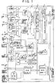
- Fig. 1 illustrates the block arrangement of the teleconference terminal equipment in this embodiment.
- the teleconference terminal equipment of this embodiment comprises a camera 1, an LCD (liquid-crystal display) 2, dial function keys 3, a VSW (video switch) 4, a picture codec 5, a telephone control man-machine interface 6, a multipoint conversation control 7, a multimedia multiplexing/demultiplexing and interterminal signal control unit 8, a network interface and communications network control unit 9, a D/R (driver) 10, a VDT (voltage detector) 11, a audio codec 12, an ASW (audio switch) 13, a hands-free set 14, a handset 15, a G3-FAX interface 16, a V11 D/R 17, an RS422 D/R 18, an RS232C D/R 19, a data multiplexor/demultiplexor 20, a communication interface matching section 21, a bus SW (switch) 22, communication ports 23 ⁇ 25, a control unit 26, peripheral device control interfaces 27 ⁇ 28, and a no-voltage contact 31.
- a D/R driver
- VDT voltage detector
- ASW audio switch
- the teleconference terminal equipment comprises a video I/O interface 110, an audio I/O interface 109, a microphone input 108, a G3-FAX modular jack 107, a V11/RS422 multiconnector 106, an RS232C connector 105, a mouse jack 104, a conference console connector 103, and a camera control/external device multiconnector 101.
- the network interface and communications network control unit 9 is connected to a digital communications network through the D/R 10, and it performs the communication controls and communication processing between the teleconference terminal equipment and the network, such as establishing a communication channel with the opposite communicating terminal equipment.
- the multimedia multiplexing/demultiplexing and interterminal signal control unit 8 performs various controls between the pertinent terminal equipment and the opposite terminal equipment. Besides, this control unit 8 demultiplexes video data, audio data, data to be multiplexed/demultiplexed, control data, etc. from within a received communication frame into the individual data types, and it multiplexes such types of data into a transmission communication frame.
- the video data mentioned above is interface data on the network side of the picture codec 5, while the audio data is interface data on the network side of the audio codec 12.
- the data to be multiplexed/demultiplexed is interface data with respect to the data multiplexor/demultiplexor 20.
- the control data is transferred between the control unit 8 and the control unit 26.
- the data multiplexor/demultiplexor 20 further demultiplexes the data demultiplexed from within the received communication frame by the multimedia multiplexing/demultiplexing and interterminal signal control unit 8, into individual data types in accordance with protocols stipulated with the opposite communicating terminal equipment beforehand.
- the multimedia multiplexing/demultiplexing and interterminal signal control unit 8 transfers FAS or BAS data within the frame to and from the control unit 26, audio data to and from the audio codec 12, video data in, e. g., a frame stipulated in CCITT Recommendation H. 261 to and from the picture codec 5, and data to-be-multiplexed/demultiplexed to and from the data multiplexor/demultiplexor 20.
- MLP data is contained in the frame stipulated in CCITT Recommendation H. 221, it is transferred between the control unit 8 and either the control unit 26 or the data multiplexor/demultiplexor 20 under the control of the control unit 26.
- the data multiplexor/demultiplexor 20 demultiplexes the data to-be-demultiplexed into G3-FAX data, computer data, various control data, etc. in accordance with the protocols stipulated with the opposite communicating terminal equipment beforehand, and it delivers the demultiplexed data items to the G3-FAX modular jack 107, V11/RS422 multiconnector 106 and RS232C connector 105.
- the data multiplexor/demultiplexor 20 multiplexes the data to-be-multiplexed delivered from the G3-FAX modular jack 107, V11/RS422 multiconnector 106 and RS232C connector 105 and delivers the multiplexed data items to the multimedia multiplexing/demultiplexing and interterminal signal control unit 8.
- the multipoint conversation control 7 performs the controls required for the start and proceeding of the multipoint teleconference. In contrast, in the case of holding no multipoint teleconference, the control 7 merely relays data.
- the VDT 11 is a means for detecting the feed voltage of the pertinent terminal equipment.
- the camera 1 picks up a picture, which is presented as a display output by the LCD 2.
- the VSW 4 is a video switch which changes-over the connection of the picture codec 5 with the camera 1, LCD 2 and video I/O interface 110.
- the video input/output of an external video I/O device can be connected with the video I/O interface 110.
- the picture codec 5 codes a picture signal supplied through the VSW 4, and delivers the coded signal to the multimedia multiplexing/demultiplexing and interterminal signal control unit 8 through the multipoint conversation control 7.
- the picture codec 5 decodes the video data demultiplexed from the received communication frame by the control unit 8 and delivers an output through the VSW 4.
- the hands-free set 14 is a microphone and a loudspeaker for freeing hands.
- the G3-FAX interface 16 is a modular jack to which a group 3 type facsimile can be connected.
- the audio input/output of an external audio I/O device can be connected to the audio I/O interface 109.
- An external microphone can be connected to the microphone input 108.
- the ASW 13 is an audio switch which changes-over the connection of the audio codec 12 with the hands-free set 14, handset 15, G3-FAX interface 16, audio I/O interface 109 and microphone input 108.
- the audio codec 12 codes a speech signal supplied through the ASW 4, and delivers the coded signal to the multimedia multiplexing/demultiplexing and interterminal signal control unit 8 through the multipoint conversation control 7.
- the audio codec 12 decodes the audio data demultiplexed from the received communication frame by the control unit 8 and delivers an output through the ASW 13.
- the audio codec 12 is connected to the V11/RS422 multiconnector 106 through the V11 D/R 17.
- the dial function keys 3 are keys for accepting the instructions of a user.
- the telephone control man-machine interface 6 controls the ASW 13 in accordance with a key input from the dial function keys 3, so as to connect the audio codec 12 with the hands-free set 14, handset 15, G3-FAX interface 16, audio I/O interface 109 and microphone input 108.
- the instruction based on the key input is transferred to the multipoint conversation control 7 through the telephone control man-machine interface 6.
- the multipoint conversation control 7 controls the multipoint teleconference.
- the G3-FAX interface 16 delivers a signal to-be-transmitted supplied from the G3 FAX (group 3 type facsimile) being an analog FAX connected to the G3-FAX connector 107, to the audio codec 12 through the ASW 13 in the case of treating the FAX data as audio data, while it digitizes the signal to-be-transmitted into a code and delivers the code to the data multiplexor/demultiplexor 20 in the case of treating the FAX data as data to-be-multiplexed.
- G3 FAX group 3 type facsimile
- the G3-FAX interface 16 when supplied with received data toward the G3 FAX by the audio codec 12, the G3-FAX interface 16 supplies the G3-FAX modular jack 107 with the received data as it is, and when supplied with received data toward the G3 FAX by the data multiplexor/demultiplexor 20, the G3-FAX interface 16 decodes the received data into an analog signal and delivers the analog signal to the G3-FAX modular jack 107.
- the RS232C connector 105 serves as an RS232C interface, and it is a connector to which a computer, a word processor or an electronic blackboard can be connected.
- This RS232C connector 105 is connected to the control unit 26 or the data multiplexor/demultiplexor 20 through the bus SW 22.
- the communication interface matching section 21 matches the data rate of the input/output data of the data multiplexor/demultiplexor 20 with that of the input/output data of the RS232C interface 105.
- the communication ports 24 and 25 are ones which the control unit 26 uses in relation to the RS232C interface 105.
- the V11/RS422 multiconnector 106 serves as a V11 interface and an RS422 interface, and it is a connector for connecting an external device. In this embodiment, an example in which a conference unit is connected will be described later.
- the multiconnector 106 as the RS422 interface is connected to the control unit 26 through the bus SW 22.
- the communication port 23 is one which the control unit 26 uses in relation to the RS422 interface 106.
- the multiconnector 106 as the V11 interface is connected to the data multiplexor/demultiplexor 20.
- peripheral device control interfaces 27 and 28 control the various components in the teleconference terminal equipment, a mouse connected to the mouse jack 104, and a conferential console connected to the conference console connector 103. Also, they control an external device such as external camera through the camera control/external device multiconnector 101.
- the camera control/external device multiconnector 101 transfers the command of the control unit 26 to the external device by means of the no-voltage contact 31.
- Fig. 2 illustrates the construction of the picture codec 5.
- the picture codec 5 includes an A/D (analog-to-digital) converter 200, a video coder 201, a still picture coder 202, a variable-length coder 203, a BCH (Bose-Chaudhuri-Hocquenghem code unit) 204, a PinP (picture-in-picture) processor 205, a video decoder 206, a D/A (digital-to-analog) converter 220, a still picture decoder 207, a variable-length decoder 208, a BCH 209, and video switches 210, 211, 212, 213, 214 and 215.
- A/D analog-to-digital converter 200
- a still picture and a video are treated, but the signals thereof are digitized by the single A/D converter 200.
- the still picture and the video are not usually transmitted at the same time on account of the limited transmission capacity of a communication channel employed in a digital communications network. That is, in order to quickly send the still picture of large data quantity to the opposite communicating terminal equipment, the transmission of the video is usually suspended during that of the still picture.
- a still picture and a video which have been received are displayed in a multiplexed state within an identical frame through the PinP processor 205 to be detailed later, thereby making it more convenient for use.
- the still and videos are multiplexed into the identical frame before analogizing the signals of the respective pictures, whereby the single D/A converter 220 suffices for turning the picture data of both the pictures into analog signals.
- the A/D converter 200 When supplied with a picture signal through the VSW 4, the A/D converter 200 converts the picture signal into a digital signal.
- a digital signal is assumed as the picture signal to-be-input in this embodiment, even a signal conforming to another standard such as PAL or RGB can be similarly processed.
- the digitized picture data is transferred to the PinP processor 205 as the picture data of the pertinent terminal equipment itself.
- the video switches 210 and 211 deliver the digitized picture data to either the video coder 201 or the still picture coder 202, depending upon whether the input picture signal is for a still picture or a video.
- the video coder 201 codes the delivered picture data in accordance with code rules based on the DCT (discrete cosine transform) stipulated in CCITT Recommendation H. 261. Also, the still picture coder 202 codes the delivered picture data in accordance with predetermined code rules. When supplied with the coded picture data through the video switch 212 from either the video coder 201 or the still picture coder 202, the variable-length coder 203 turns the supplied image data into a variable-length code in accordance with variable-length code rules stipulated in CCITT Recommendation H. 261.
- the BCH 204 When supplied with the variable-length code of the image data from the variable-length coder 203, the BCH 204 adds BCH data for error correction to the supplied code into video data and transfers the video data to the multimedia multiplexing/demultiplexing and interterminal signal control unit 8 through the multipoint conversation control 7.
- the BCH 209 when the BCH 209 is supplied with video data or still picture data through the multipoint conversation control 7 from the multimedia multiplexing/demultiplexing and interterminal signal control unit 8, it checks BCH data for error correction and delivers the error-corrected video data or still picture data to the variable-length decoder 208.
- This variable-length decoder 208 decodes the delivered picture data in accordance with the variable-length code rules stipulated in CCITT Recommendation H. 261.
- the data decoded by the variable-length decoder 208 is transferred to either the video decoder 206 or the still picture decoder 207 through the video switch 215, depending upon whether it is video data or still picture data.
- the video decoder 206 When supplied with the video data decoded by the variable-length decoder 208, the video decoder 206 decodes it in accordance with the code rules stipulated in CCITT Recommendation H. 261. Also, when supplied with the still picture data decoded by the variable-length decoder 208, the still picture decoder 207 decodes it in accordance with predetermined code rules such as code rules conforming to the JPEG algorithm of the ISO Standard. The picture data decoded by the video decoder 206 or the still picture decoder 207 is transferred as received motion picture data or received still picture data to the PinP processor 205 through the corresponding video switch 213 or 214.
- the PinP processor 205 performs a PinP process to be described later, by the use of the image data of the pertinent terminal equipment itself transferred from the A/D converter 200 and the image data decoded by the video decoder 206 or the still picture decoder 207, and it supplies the D/A converter 220 with the resulting image data which has been subjected to the PinP process.
- the D/A converter 220 converts the supplied image data into an analog signal, which is delivered to the video switch 4.
- the picture signal is presented as a display output on the LCD 2 or the like in accordance with the operation of the video switch 4.
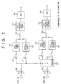
- Fig. 3 illustrates the construction of the PinP processor 205.
- the PinP processor 205 includes a self-picture frame memory 301, a still-picture frame memory 302, a motion-picture frame memory 303, MUX'es (multiplexors) 305, 306 and 307, a major-frame address generator 308, a minor-frame address generator 309, a display frame timing controller 310, and MUX 311.
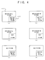
- the "PinP process” is a process for producing a picture-in-picture frame from a plurality of pictures. That is, it is a process for multiplexing and outputting two picture data in order that different output pictures may be displayed in a major frame area and a minor frame area as illustrated in Fig. 4.
- the two picture data are selected from among the three picture data of the self-picture data transferred from the A/D converter 200, the received still picture data transferred from the still picture decoder 207 and the received motion picture data transferred from the video decoder 206, and they are multiplexed and output so as to be displayed in the major and minor frame areas.
- the PinP process is carried out by selecting two from the three picture data of the self-picture data, received still picture data and received motion picture data, six types of picture-in-picture frames can be produced as shown at symbols (a) ⁇ (f) in Fig. 4.
- the PinP process of the PinP processor 205 proceeds as stated below.
- the self-picture frame memory 301 stores the transferred self-picture data therein.
- the still-picture frame memory 302 stores the received still picture data therein.
- the motion-picture frame memory 303 stores the received motion picture data therein. The contents of the individual frame memories are sequentially updated.
- the major-frame address generator 308 generates addresses for fetching the data of a picture to be displayed in the major frame area, in display sequence from the frame memory in which the picture data are stored. While the major-frame address generator 308 is generating the data addresses of the above picture corresponding to the major frame area, the minor-frame address generator 309 generates in parallel with the address generation of the generator 308, addresses for fetching the data of a picture to be displayed in the minor frame area, in display sequence from the frame memory in which the picture data are stored. On this occasion, the address generation timings of the minor-frame address generator 309 are controlled by the display timing controller 310. Besides, the picture to be displayed in the minor frame area must be reduced in size as shown in Fig. 4. Therefore, the minor-frame address generator 309 generates skipped addresses in accordance with a reduction rate so as to thin out pixels and then fetch the picture data from the frame memory.
- the addresses generated by the major-frame address generator 308 are afforded through the corresponding MUX 305, 306 or 307 to the frame memory 301, 302 or 303 in which the picture data to be displayed in the major frame area are stored.
- the addresses generated by the minor-frame address generator 309 are afforded through the corresponding MUX 305, 306 or 307 to the frame memory 301, 302 or 303 in which the picture data to be displayed in the minor frame area are stored.
- the MUX 311 selects and delivers the picture data fetched from the frame memory in which the picture data to be displayed in the minor frame area are stored. At any other time, the MUX 311 selects and delivers the picture data fetched from the frame memory in which the picture data to be displayed in the major frame area are stored. A change-over timing for these operation modes of the MUX 311 is controlled by the display timing controller 310.
- the frame memories of the PinP processor 205 may well be shared for frame memories which the video coder 201, still picture coder 202, video decoder 206 and still picture decoder 207 use for the coding and the decoding.
- Fig. 5 illustrates the construction of the G3-FAX interface 16.
- the interface 16 includes a hybrid 501, a route SW (switch) 502, a codec 503 for the facsimile, and a FAX sending/receiving call control 504.
- the FAX sending/receiving call control 504 When the FAX sending/receiving call control 504 is informed of the reception of G3-FAX data through the peripheral device control interface 27 by the control unit 26, it applies a ringer signal to the G3-FAX modular jack 107. In addition, the FAX sending/receiving call control 504 detects the off-hook or on-hook condition of the G3 FAX connected with the G3-FAX modular jack 107 and reports the detected condition to the control unit 26 through the peripheral device control interface 27. Besides, if necessary, the control 504 reports the content of dialing in the G3 FAX connected with the G3-FAX modular jack 107, to the control unit 26 through the peripheral device control interface 27.
- the hybrid 501 matches the half-duplex interface of the G3-FAX modular jack 107 with the full-duplex interface of the route SW side.
- the route SW 502 has been informed to the effect of treating the G3-FAX data as data to-be-multiplexed, through the peripheral device control interface 27 by the control unit 26, it connects the hybrid 501 to the audio codec 12.
- the audio codec 12 codes the data sent by the connected G3 FAX and transfers the coded data as audio data to the multimedia multiplexing/demultiplexing and interterminal signal control unit 8 through the multipoint conversation control 7.
- the route SW 502 in a case where the route SW 502 has been informed to the effect of treating the G3-FAX data as audio data, through the peripheral device control interface 27 by the control unit 26, it connects the hybrid 501 to the codec 503 for the FAX.
- the FAX codec 503 codes the sent data of the connected G3 FAX in accordance with the ⁇ /A rules, the ADPCM or the like, and transfers the coded data as data to-be-multiplexed to the multimedia multiplexing/demultiplexing and interterminal signal control unit 8 through the data multiplexor/demultiplexor 20.
- the ordinary G3 FAX can be connected to the teleconference terminal equipment and then used without altering the interface thereof. Furthermore, the G3-FAX data is coded using the FAX codec 503 and then treated as the data to-be-multiplexed, whereby a telephone conversation is possible with the audio codec 12 even during communications with the G3 FAX.
- the teleconference terminal equipment can have an external camera, an external monitor, an external microphone/external loudspeaker, etc. connected thereto by the video I/O interface 110, the audio I/O interface 109, the microphone input 108, etc.
- the camera control/external device multiconnector 101 is a connector for controlling the external camera as well as illumination therefor, and the external microphone among the aforementioned external I/O devices.
- the control employing this multiconnector 101 is realized in such a way that the control unit 26 controls the no-voltage contact such as the relay contact 31 in compliance with an instruction from the dial function keys 3, an instruction from the console connected to the conference console connector 103, or control data received from the opposite communicating terminal equipment and transferred through the multimedia multiplexing/demultiplexing and interterminal signal control unit 8.
- the control unit 26 receives the control data in the form of the FAS, BAS or MLP data from the opposite communicating terminal equipment and controls the no-voltage contact 31 in accordance with the received control data.
- Fig. 6 illustrates the construction of the camera control/external device multiconnector 101.
- the multiconnector 101 contains the signals of spare 613; zooming 612, 611; focusing 610, 609; illumination 608; wiper 607; panning 606, 605; tilting 604, 603; camera/microphone changing-over 602, 601; and power source 600.
- control unit 26 can control the zooming and focusing of the external camera, and the illumination, a wiper, and panning and tilting for the external camera, through the camera control/external device multiconnector 101. Also, it can control the change-over between the camera and the microphone, and the turn-ON/OFF of the power source of any desired external device through the multiconnector 101.
- V11/RS422 multiconnector 106 Next, the V11/RS422 multiconnector 106 will be explained.
- the V11/RS422 multiconnector 106 is a connector which includes a V11 interface and an RS422 interface.
- the RS422 interface within the V11/RS422 multiconnector 106 is connected with the control unit 26 through the communication port 23.
- the control unit 26 transfers control data to and from the conference unit by the use of the RS422 interface.
- the V11 interface within the V11/RS422 multiconnector 106 is connected to the data multiplexor/demultiplexor 20 and the audio codec 12.
- the data multiplexor/demultiplexor 20 demultiplexes control data and data to-be-demultiplexed supplied from the multimedia multiplexing/demultiplexing and interterminal signal control unit 8, and it delivers the resulting data to the V11 interface.
- the data multiplexor/demultiplexor 20 multiplexes control data and data to-be-multiplexed delivered from the V11 interface, with FAX data etc. delivered from the G3-FAX interface 16, and it supplies the resulting data to the multimedia multiplexing/demultiplexing and interterminal signal control unit 8.
- MPL data can be used as the control data.
- the data which is delivered from the data multiplexor/demultiplexor 20 to the V11 interface is in the form of the actual burst data demultiplexed and extracted from the communication frame.
- the data which is delivered from the V11 interface to the data multiplexor/demultiplexor 20 is burst data having the same transfer rate as that of data contained in the communication frame.
- the data area and control data area of the communication frame can be opened to the exterior as they are. Accordingly, the V11 interface can freely utilize the predetermined data area or control data area contained in the communication frame.
- Fig. 7 illustrates the construction of the V11/RS422 multiconnector 106.
- parts 700 ⁇ 702 constitute the RS422 interface, and parts 703 ⁇ 710 the V11 interface.
- the RS422 interface includes the lines of transmission data 700, reception data 701 and a transfer clock 702.
- the V11 interface includes the lines of sending data 703, a sending burst clock 704 synchronized with sending burst data, a sending frame sink 705, receiving data 706, a receiving burst clock 707 synchronized with receiving burst data, a receiving frame sink 708, and two basic clocks 709, 710.
- Fig. 8(a) is a perspective view of the terminal equipment seen obliquely from the front thereof, while Fig. 8(b) is a rear view of the essential portions thereof showing the arrangement of connectors.
- numeral 1000 indicates the teleconference terminal equipment.
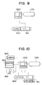
- Fig. 9 shows the teleconference system which is suitable for the personal telephonic communications between one person and another
- Fig. 10 shows the teleconference system which is suitable for a teleconference among a small number of people
- Fig. 11 shows the teleconference system of simplified type which is used for a teleconference
- Fig. 12 shows the teleconference system which is suitable for a regular teleconference
- Fig. 13 shows the teleconference system which is suitable for a larger teleconference.
- a G3 FAX 900 a computer 901 such as a personal computer or word processor, a camera 903, a monitor 904, a microphone 905, a camera pan-tilter 906, a conference console 907, etc.
- a computer 901 such as a personal computer or word processor
- the video I/O interface 110 can be connected by the video I/O interface 110, audio I/O interface 109, microphone input 108, G3-FAX modular jack 107, V11/RS422 multiconnector 106, RS232C connector 105, mouse jack 104, conference console connector 103, and camera control/external device multiconnector 101.
- the teleconference systems can be flexibly constructed in accordance with intended uses.
- the external interface based on the digital data of the audio codec 12 is included in the V11/R422 multiconnector 106 as stated before. As shown in Fig. 12, therefore, a digital echo canceler 1200 of high performance can be disposed outside if it is need.
- a G3 FAX 900 data processing devices 901 such as a personal computer or word processor and an electronic blackboard, a camera 903, a monitor 904, microphones 905, a camera pan-tilter 906, a conference console 907, etc. may well be connected through a conference unit 1300 so as to realize higher degrees of conference functions.
- the conference unit 1300 includes a video controller 1301, an audio controller 1302, a unit controller 1303, a video processor 1305 and a power source unit 1306.
- the video controller 1301 is connected to the video I/O interface 110 of the teleconference system.
- the audio controller 1302, unit controller 1303 and video processor 1305 are connected with the V11/RS422 multiconnector 106 of the teleconference system through the unshown data interface unit thereof.
- the unit controller 1303 controls any of the constituents of the conference unit 1300 in compliance with an instruction from the conference console 907, an instruction from the control unit 26 of the teleconference system as delivered through the RS422 interface, or control data received through the V11 interface from the opposite communicating terminal equipment. In addition, the unit controller 1303 transfers data received through the V11 interface from the opposite communicating terminal equipment, between this V11 interface and the data processing devices 901 such as the personal computer or word processor and the electronic blackboard.
- the video controller 1301 and the still picture processor control the change-over between, for example, the camera and the monitor which are connected to the video I/O interface 110 of the teleconference system.
- the audio controller 1302 controls the change-over between, for example, the microphone and the loudspeaker which are connected to the audio codec 12 of the teleconference system through the V11 interface. In addition, the audio controller 1302 performs an echo canceling process as may be needed.
- the video processor 1305 performs the control of the camera pan-tilter 906.
- the pertinent terminal equipment can communicate with the conference unit connected to the opposite terminal equipment through the mutual direct controls which are performed as needed by the use of the data area and the control data area opened to the external devices as stated before, and the intended uses of teleconference systems can be flexibly coped with.
- Fig. 14 illustrates the construction of the teleconference system according to this embodiment.
- the embodiment includes a teleconference module 2001 connected to a digital communications network, a control keyboard 2002, microphones 2003, a document photographing stand 2004, an electronic blackboard 2005, a video tape recorder 2006, a display unit 2007 and a display unit rack 2008 for housing the display unit 2007 therein.
- the display unit 2007 shall be explained as being a CRT display device which has a built-in loudspeaker.
- the illustrated teleconference system is fundamentally configured of the teleconference module 2001, the display unit 2007 connected to the teleconference module 2001, the control keyboard 2002 connected to the teleconference module 2001, and the microphones 2003 connected to the teleconference module 2001 through the control keyboard 2002. If necessary, the system is expanded by connecting the document photographing stand 2004, electronic blackboard 2005 and video tape recorder 2006 to the teleconference module 2001. In addition, as will be described later, an external camera, a facsimile machine and a small-sized computer can be connected to the teleconference module 2001 if it is need.
- the teleconference system of this embodiment features the teleconference module 2001 in the shape of a box.
- a teleconference can be held in any of a conference room, a living room, etc. where ordinary display units are installed.
- the teleconference module 2001 has a built-in camera, and it has geometries such that it can be put on the top plate of the rack 2008 housing the display unit 2007 therein or put directly on the display unit 2007.
- the teleconference module 2001 codes an image picked up over the top plate of the rack 2008 or over the display unit 2007 by the built-in camera, and transmits the resulting code to the opposite communicating side through the connected digital communications network. Also, it decodes the image of the opposite side received through the digital communications network and then transfers the resulting image to the display unit 2007.
- the teleconference module 2001 will be explained.
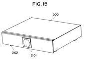
- Fig. 15 illustrates the external appearance of the teleconference module 2001 according to this embodiment.
- this teleconference module is a box-like one similar to common video tape recorders, BS (broadcasting by satellite) tuners, etc.
- numeral 2101 designates a camera window, behind which the built-in camera is mounted.
- numeral 2102 designates a rotary volume control for adjusting the sensitivity of each microphone 2003.
- Various terminals are mounted on the rear surface of the teleconference module 2001.
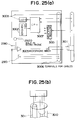
- Figs. 16(a), 16(b) and 16(c) are a front view, a side view and a rear view of the teleconference module 2001, respectively.
- the rear surface of the teleconference module 2001 is provided with two video signal input terminals 2816 and 2825, two video signal output terminals 2817 and 2824, an audio signal input terminal 2819, audio signal output terminals 2818 and 2823, a modular jack 2820 for a G3 FAX (group 3 type facsimile), a modular jack 2830 for the digital communications network, an RS232C connector 2821, a connector 2822 for the control keyboard 2002, a triple-pole terminal 2311 for connecting a power source cable, and a seesaw switch 2312 being a power switch.
- G3 FAX group 3 type facsimile
- each supporters 2320 furnished with adjusting mechanisms are provided for adjusting the spacings between the body 2310 and the installation plane of the teleconference module 2001 independently of one another.
- the inclination of the body 2310 as well as the camera included therein can be adjusted.
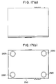
- Figs. 17(a) and 17(b) are a plan view and a bottom view of the teleconference module 2001, respectively.
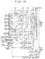
- Fig. 18 shows the internal construction of this teleconference module.
- the terminal 2830 indicates the terminal which is to be connected to the digital communications network.
- the digital communications network is assumed to be the ISDN (integrated service digital network), and the terminal 2830 to be a modular jack having eight pins.
- the teleconference module 2001 includes the camera 2807, a video switch 2806, a video amplifier 2808, a picture codec 2805, a multimedia multiplexing/demultiplexing and interterminal signal control unit 2804, a network interface and communications network control unit 2803, a audio codec 2810, an echo canceler 2811, an audio switch 2813, an audio amplifier 2812, a FAX interface 2814, a data interface 2815, a control unit 2802 and a power source 2801.
- the external I/O terminals are the two video signal input terminals 2816 and 2825, the two video signal output terminals 2817 and 2824, the audio signal input terminal 2819, the audio signal output terminals 2818 and 2823, the modular jack 2820 for the G3 FAX, the RS232C connector 2821, the connector 2822 for the control keyboard 2002, the triple-pole terminal 2311 for connecting the power source cable, and the connector 2822 for the control keyboard 2002.
- These connectors and the above terminal 2803 are arranged on the rear surface of the teleconference module 2001 as stated before.
- the network interface and communications network control unit 2803 is connected to the ISDN through the connector 2830, and it performs the communication controls and communication processing between the pertinent teleconference terminal equipment and the network, such as establishing a communication channel with the opposite communicating terminal equipment.
- the multimedia multiplexing/demultiplexing and interterminal signal control unit 2804 performs various controls between the pertinent terminal equipment and the opposite terminal equipment. Besides, this control unit 2804 demultiplexes video data, audio data, data to be multiplexed/demultiplexed, control data, etc. from within a received communication frame into the individual data types, and it multiplexes such types of data into a transmission communication frame.
- the video data mentioned above is interface data on the network side of the picture codec 2805, while the audio data is interface data on the network side of the audio codec 2810.
- the data to be multiplexed/demultiplexed is interface data with respect to the data interface 2815 and the FAX interface 2814.
- the control data is transferred between the control unit 2804 and the control unit 2802.
- the multimedia multiplexing/demultiplexing and interterminal signal control unit 2804 further demultiplexes the data demultiplexed from within the received communication frame, into G3-FAX data, computer data, various control data, etc. in accordance with protocols stipulated with the opposite transmission terminal equipment beforehand, and it delivers these data to the G3-FAX modular jack 2820 and RS232C connector 2821 through the FAX interface 2814 and data interface 2815, respectively.
- control unit 2804 accepts data to be transmitted in a multiplexed state, from the G3-FAX modular jack 2820 and RS232C connector 2821.
- the camera 2807 picks up an image.
- the video switch 2806 supplies the picture codec 2805 with an input from the video signal input terminal 2816, instead of an input from the camera 2807.
- the document photographing stand 2004 and the external camera can be connected to the video input terminals 2816 and 2825. Accordingly, when the external camera for photographing conferees is substituted for the built-in camera 2807, it can be used in the state in which it is housed in the display unit rack 2008.
- the picture codec 2805 codes an input picture signal, and delivers the resulting coded signal to the multimedia multiplexing/demultiplexing and interterminal signal control unit 2804. In addition, it decodes video data demultiplexed from within a received communication frame by the control unit 2804 and then delivers the resulting decoded data to the video signal output terminals 2817 and 2824 through the video amplifier 2808.
- the video signal output terminal 2824 is connected with the external video input terminal of the display unit 2007 so as to display a received picture.
- the video signal output terminal 2817 is connected with the external video input terminal of the video tape recorder 2006 so as to record the contents of the teleconference as and when required.
- the audio input and output terminals 2818, 2819 and 2823 can have the audio input and outputs of external audio devices connected thereto.
- the audio switch 2813 is one by which any of an input from the G3 FAX connected to the G3-FAX modular jack 2820, an input from a device connected to the audio input interface 2819, and an input from the microphones 2003 coupled with the control keyboard 2002 connected to the connector 2822 is transferred to the audio codec 2810 through the echo canceler 2811.
- the audio codec 2810 codes an input speech signal, and delivers the resulting coded signal to the multimedia multiplexing/demultiplexing and interterminal signal control unit 2804. In addition, it decodes audio data demultiplexed from within a received communication frame by the control unit 2804 and then delivers the resulting decoded data to the audio output terminals 2818 and 2823 through the echo canceler 2811 as well as the audio amplifier 2812.
- the audio output terminal 2818 has the external audio input terminal of the video tape recorder 2006 connected thereto, while the audio output terminal 2823 has the external audio input terminal of the display unit 2007.
- the echo canceler 2811 performs an echo canceling process between the speech signal decoded from the audio data and the speech signal delivered from the audio switch 2813, thereby preventing the occurrence of howling during communications.
- the howling may well be prevented by replacing the echo canceler 2811 with an echo suppressor which suppresses a selected one of the outputs to the audio amplifier 2812 and the input from the audio switch 2813.
- the FAX interface 2814 delivers a signal to-be-transmitted supplied from the G3 FAX being an analog FAX connected to the G3-FAX modular jack 2820, to the audio codec 2810 in the case of treating the FAX data as audio data, while it digitizes the signal to-be-transmitted into a code and delivers the code to the multimedia multiplexing/demultiplexing and interterminal signal control unit 2804 in the case of treating the FAX data as data to-be-multiplexed.
- the FAX interface 2814 when supplied with received data toward the G3 FAX by the audio codec 2810, the FAX interface 2814 supplies the G3-FAX modular jack 2820 with the received data as it is, and when supplied with received data toward the G3 FAX by the multimedia multiplexing/demultiplexing and interterminal signal control unit 2804, the FAX interface 2814 decodes the received data into an analog signal and delivers the analog signal to the G3-FAX modular jack 2820.
- the RS232C connector 2821 serves as an RS232C interface, and it is a connector to which a computer, a word processor or an electronic blackboard can be connected. This RS232C connector 2821 is connected to the control unit 2802 or the multimedia multiplexing/demultiplexing and interterminal signal control unit 2804 through the data interface 2815.
- the control unit 2802 performs serial data communications with the control keyboard 2002. Besides, it performs various controls for the constituents of the teleconference module 2001, for example, the display control of a menu picture to be described later, on the basis of data transferred from the multimedia multiplexing/demultiplexing and interterminal signal control unit 2804 and data transferred from the control keyboard 2002.
- the external device interfaces of the teleconference module 2001 will be put in order in Table 1 below: TABLE 1 Items Contents External Inputs and Outputs Video Inputs 2 75 ⁇ 1 Vp-p Video Outputs 2 Unbalance RCA pin jacks Audio Input 1 Above 40 k ⁇ 312 mVrms Audio Outputs 2 Below 2 k ⁇ RCA pin jacks FAX Interface 1 Connecting G3 FAX Data Interface 1 RS232C, 1.2 ⁇ 9.6 kb/s
- the picture codec 2805 codes and decodes pictures in conformity with algorithms stipulated in CCITT Standard, H. 261.
- a picture codec is implemented with two circuit boards each having a size nearly equal to the A5-format in, for example, a commercially-available video telephone set HV-100 (trade name) manufactured by Hitachi, Ltd.
- HV-100 commercially-available video telephone set
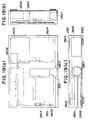
- Figs. 19(a), 19(b) and 19(c) are a schematic plan view, a schematic side view and a schematic front view, respectively, showing the internal structure of the teleconference module 2001.
- the teleconference module 2001 is configured of the camera 2807 and six circuit boards 2601 ⁇ 2606.
- numeral 2310 indicates the body of this teleconference module, and numeral 2320 each supporter furnished with the adjusting mechanism.
- the six circuit boards 2601 ⁇ 2606 are mounted inside the body 2310 as depicted in the figures.
- the circuit boards 2601 and 2602 are ones on which the picture codec 2805 is installed, and each of which has nearly the same size as the A5-format in the video telephone set HV-100.
- the circuit board 2603 is one which carries the multimedia multiplexing/demultiplexing and interterminal signal control unit 2804, network interface and communications network control unit 2803, audio codec 2810, echo canceler 2811, FAX interface 2814, data interface 2815, control unit 2802, video switch 2806 and video amplifier 2808.
- the circuit board 2604 carries the echo canceler 2811, audio amplifier 2812 and audio switch 2813.
- the circuit boards 2605 and 2606 carry the power source 2801.
- the picture codec 2805 is configured of the two circuit boards each having the A5-size approximately, whereby the teleconference module 2001 can be realized as the box-shaped module whose size is substantially equal to the size of, e. g., an ordinary video tape recorder for domestic use.
- the size of each of the circuit boards 2601 and 2602 is 168 mm ⁇ 184 mm, that of the circuit board 2603 is 256 mm ⁇ 210 mm, that of the circuit board 2604 is 140 mm ⁇ 260 mm, that of the circuit board 2605 is 156 mm ⁇ 116 mm, and that of the circuit board 2606 is 227 mm ⁇ 88 mm.
- the body 2310 of the teleconference module 2001 is 431 mm wide, 82 mm high and 300 mm deep.
- the teleconference module 2001 can be satisfactorily constructed using the circuit boards 2603, 2604, 2605 and 2606 of the aforementioned sizes.
- the teleconference module 2001 has the dimensions of a height within 150 mm, a width within 500 mm and a depth within 450 mm, it can be used without hindrance in the state in which it is placed on the display unit rack 2008 or the display unit 2007 as shown in Fig. 14. In addition, it can be housed in the rack 2008 without hindrance.
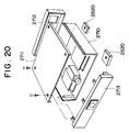
- Fig. 20 illustrates the situation of the assemblage of the teleconference module 2001.
- the teleconference module 2001 is assembled in such a way that a top panel 2711, a front panel 2712, a back panel 2713 and the adjustable supports 2320 are attached to a body base 2710 on which the camera 2807 and the circuit boards 2601 ⁇ 2606 are mounted.
- control keyboard 2002 will be explained.
- Fig. 21 shows the external appearance of the control keyboard 2002.
- the control keyboard 2002 is in the shape of a sector.
- Various keys are arranged on the upper surface of this control keyboard, while terminals 2910 for connecting microphones and also terminals for cables for connections with the teleconference module 2001 are disposed on the rear surface.
- a built-in microphone 2920 is arranged in the front of this control keyboard.
- Numeral 2901 indicates a volume control for controlling the sound volume of a loudspeaker 2104 built into the teleconference module 2001.
- Numeral 2902 indicates keys for controlling the zooming functions of the camera 2807.
- Denoted by numeral 2903 are numerical and function keys which serve to control the communication functions of the teleconference module 2001, and which are equivalent to those of an ISDN terminal equipment. In this embodiment, however, the numerical keys are shared with alpha keys. Keys 2904 serve to control a pan-tilter which is sometimes installed for the camera 2807 of the teleconference module 2001.
- keys 2905 serve to change-over the picture qualities of pictures to-be-transmitted
- a key 2906 serves to change-over the input of the built-in camera 2907 of the teleconference module 2001 and the input of the external camera set on, e. g., the document photographing stand 2004 as a transmission picture
- keys 2907 and 2908 serve to changeover transmission data from video or audio data to input data from the facsimile machine and small-sized computer connected to the teleconference module 2001, respectively.
- indicators such as an LED 2909 for indicating the closure of power supply, are provided on the upper surface of the control keyboard 2002.
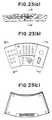
- Figs. 23(a), 23(b) and 23(c) are a front view, a plan view and a bottom view, respectively, of the control keyboard 2002.
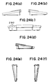
- Figs. 24(a), 24(b), 24(c), 24(d), 24(e) and 24(f) are a right side view of the control keyboard 2002, a left side view thereof, a rear view thereof, a schematic sectional view thereof taken along line A - A' in Fig. 23(a), a schematic sectional view thereof taken along line B - B' in Fig. 23(b), and a schematic sectional view thereof taken along line C - C' in Fig. 23(b), respectively.
- numeral 2910 represents the terminals for connecting the external microphones.
- Figs. 25(a) and 25(b) show the internal construction of the control keyboard 2002.
- the control keyboard 2002 includes a switching regulator 3001 by which a supply voltage fed from the teleconference module 2001 is distributed to the individual parts of this control keyboard, key switches 3002 which constitute the various keys stated before, and LED's 3003.
- a CPU 3007 which controls the key switches 3002 and the LED's 3003 while performing the serial data communications with the teleconference module 2001 by the use of data clock pulses supplied from this teleconference module.
- the built-in microphone 2920 the microphone jacks 2910 for connecting the external microphones 2003, a microphone mixer 3005 for mixing an input from the built-in microphone 2920 and inputs from the external microphones 2003, and the volume control 2901 for adjusting the levels of audio signals transferred from the audio signal output terminals 2818 and 2823 by the teleconference module 2001.
- the connections between this control keyboard 2002 and the teleconference module 2001 are collectively effected by the single composite cable 3010.
- an output from the microphone mixer 3005 is sent to the teleconference module 2001 through a transformer of 600 ohms by the use of a shielded cable 3011 which is disposed in the composite cable 3010 as shown in Fig. 25(b).
- Fig. 26 shows the external appearance of the document photographing stand 2004.
- the document photographing stand 2004 is constructed of a platen 3101, a lower link 3102, an upper link 3103 and the camera 3104. Besides, an LED 3105 is embedded in the central part of the platen 3101, and camera controlling keys 3106 are disposed at one corner of the platen 3101.
- the camera controlling keys 3106 include zooming control keys (wide angle/telescopic), an autofocusing function enabling key and a manual focusing controlling key for the camera 3104.
- the lower link 3102 is pivotally mounted on the platen 3101
- the upper link 3103 is pivotally mounted on the lower link 3102
- the camera 3104 is pivotally mounted on the upper link 3103.
- the camera 3104 can photograph, not only a document set on the platen 3101, but also spaces before and behind the platen 3101. Accordingly, when the blackboard 2005 is arranged behind the platen 3101 as shown in Fig. 14 referred to before, characters, patterns etc. written and drawn on this blackboard can be photographed and transmitted except during the photographing of the document.
- the LED 3105 embedded in the upper surface of the platen 3101 serves to facilitate the positioning of the document to-be-photographed. More specifically, when an illuminator is provided in this manner, the central point of photographing can be readily grasped with transmitted light even for a paper or the like which is placed on the platen 3101 for the photographing.
- LED's may well be disposed at the four corners of a photographing region on the platen 3101 for a document of standard size (for example, A4-format or B5-format). Owing to the transmitted light beams of such LED's, the desired region of a document larger than the standard size can be grasped and photographed more easily than with a conventional platen on which the four corners are marked.
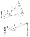
- Figs. 27(a), 27(b), 27(c) and 27(d) are a front view, a right side view, a plan view and a bottom view, respectively, of the document photographing stand 2004.
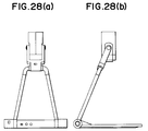
- Figs. 28(a) and 28(b) are a rear view and a left side view, respectively, of the document photographing stand 2004.
- the length l of the lower link 3102 is set so as not to exceed the length L of the platen 3101, and the length m of the upper link 3103 is set so as to be shorter than the length l of the lower link 3102.
- the width N between both the arms of the lower link 3102 is set greater than the width n between both the arms of the upper link 3103. Accordingly, as seen from a front view, a side view and a plan view depicted in Figs.
- the lower link 3102 can be folded on the platen 3101, and the upper link 3103 can be folded inside the lower link 3102.
- the document photographing stand 2004 can be carried or stored in a compact state.
- the received picture of the opposite communicating side is usually displayed on the screen of the display unit 2007.
- the teleconference module 2001 presents a minor frame at the right corner of the monitor screen and displays the self-picture thereof photographed by its own camera 2807, as illustrated in Fig. 31.
- the teleconference module 2001 displays the self-picture on the whole monitor screen, and when the key is depressed again, the module 2001 brings the screen back into the usual state and displays the picture of the opposite communicating side on the whole monitor screen.
- Such a picture-in-picture display process has been detailed in connection with the first embodiment.
- the teleconference module 2001 guides operations and reports statuses by the use of the display of the display unit 2007.
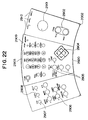
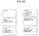
- Fig. 32 illustrates the situations of the operation guidance and status report utilizing the monitor screen.
- Letter a in Fig. 32 denotes the display of the display unit 2007 at the closure of the power supply.
- the current time is indicated at the left upper corner part of the display screen of the display unit 2007.
- the monitor display is changed as shown at b in Fig. 32, and a message for promoting a dial input is indicated.
- the numerals of the telephone No. of the opposite communicating side for the teleconference are input with the numerical keys of the control keyboard 2002, they are successively indicated as shown at c in Fig. 32.
- the teleconference module 2001 establishes a channel with the ISDN to transmit the input No., and it presents a display to the effect of calling the opposite terminal as shown at d in Fig. 32.
- an elapsed time since the beginning is indicated as shown at e in Fig. 32.
- the teleconference module 2001 offers other various functions in a menu form.
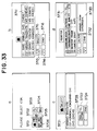
- Fig. 33 illustrates menus which are displayed on the display unit 2007.
- patterns are icons which are provided in correspondence with the offered functions.
- the icon 3701 serves to start a telephone directory function
- the icon 3702 serves to start the function of setting any of the various statuses of the teleconference module 2001 such as the communication mode and display mode thereof
- the icon 3703 serves to start the function of adjusting the time of a timepiece built into the teleconference module 2001
- the icon 3705 serves to start the function of handling information items (opposite communicating sides, telephone Nos, fees, etc.) on past communications
- the icon 3706 serves to select whether or not the time displays shown in Fig. 32 are presented.
- the icon 3704 serves to end the menu.
- the respective icons are displayed in an arrangement corresponding to the arrangement of the numerals 1 ⁇ 6 of the numerical keys of the control keyboard 2002, and the depression of the key at the corresponding position starts the function which is offered by the pertinent icon.
- a menu as shown at b in Fig. 33 is displayed. More specifically, the same pattern as the icon having started this function is indicated at the uppermost part, and the names and telephone Nos. of the opposite communicating persons already registered are indicated in an area 3711.
- the user scrolls the indication within the area 3711 by designating an icon 3713 or 3714 through the depression of the numerical key at the corresponding position and then appoints the opposite communicating person whose information is to be handled, by designating a select icon 3715 through the depression of the numerical key at the corresponding position.
- An icon 3716 is one for returning to the menu picture a in Fig. 33.
- a menu shown at c in Fig. 33 is displayed.
- the patterns of the icon which has started the corresponding function and the icon which was indicated at the uppermost part of the parent menu of this menu are indicated at the uppermost part, and all information items registered as relevant to the selected communicating person are indicated in an area 3721.
- a TEL icon 3722 serves to designate a transmission to the opposite communicating person indicated in the area 3721.
- the teleconference module 2001 calls the selected communicating person in accordance with the registered information and ends the menu processing steps, to shift to the display shown at d in Fig. 32.
- An icon 3724 in the menu c in Fig. 33 serves to alter the registered information by way of example.
- the function of, e. g., altering the registered information is indicated, and a new menu corresponding to the function is displayed.
- necessary input functions are similarly assigned to the keys of the control keyboard 2002 so as to accept the user's inputs of information.
- alternatives to an input character are sequentially changed-over in accordance with a predetermined input key.
- the conversion of inputs into Chinese characters can be realized by expanding the function of a predetermined input key.
- a menu shown at d in Fig. 33 is displayed.
- the current statuses of the teleconference module 2001 are indicated in an area 3731.
- the user designates any indicated item and also designates an alternative icon 3732 in accordance with steps similar to those of the operation of the menu b in Fig. 33, whereby the status of the designated item can be set anew to another alternative registered beforehand.
- the display unit 2007 has been described as the CRT display device, it may well be a different one such as a liquid-crystal display device or a projection display device.
- this embodiment has been chiefly described as to the case of placing the teleconference module 2001 on the display unit 2007 or the display rack 2008, the teleconference module 2001 may well be placed and used at any position where the built-in camera 2807 thereof can photograph the user.
- the teleconference module 2001 can similarly realize a video telephone system.
- this teleconference module 2001 when this teleconference module 2001 is connected to any of television receivers placed in the living rooms of most homes, the video telephone system can be constructed.
- the teleconference module of this embodiment might be named a "video telephone module", but these modules are substantially identical.
- the teleconference module which is the single equipment being small in size and easily portable and which can realize the teleconference system and the video telephone system when connected to the existing display unit.
Abstract
Description
- The present invention relates to a teleconference system which exchanges speech, video etc. through a communication circuit in real time.
- Heretofore, a video telephone system and a teleconference system have been known as systems in each of which speech, video etc. are exchanged through a communication circuit in real time.
- The video telephone system is chiefly intended for telephonic communications between one person and another similar to a conventional telephone. On the other hand, the teleconference system is intended for teleconference between a number of people, and it has a construction in which importance is attached to meeting functions required for such a teleconference.
- A prior-art equipment for the teleconference system is constructed by combining independent devices such as a display unit, a codec, a microphone and a console. In some cases, a document camera, an electronic blackboard and a small-sized computer are further combined in accordance with functions required for conferences.
- There is also a teleconference equipment wherein fundamental devices are housed in a single rack so as to be movable, thereby dispensing with the need for an exclusive conference room.
- Techniques relevant to these equipments are disclosed in the official gazettes of Japanese Patent Applications Laid-open No. 39790/1990 and No. 22989/1990.
- In addition, Japanese Patent Applications relevant to teleconference systems filed by the assignee of the present application are Patent Applications Laid-open Nos. 166884/1991 and 120889/1992, and Patent Applications Nos. 406984/1990, 25987/1991, 25991/1991, 34009/1991, 174025/1991, 174031/1991 and 174049/1991.
- Most of the video telephone systems in the prior art do not have the high-degree functions necessary for teleconferences such as the teleconference systems have, because it is presumed that they are only used between one person and another. On the contrary, teleconference systems in the prior art are inherently endowed with such high-degree functions. In consequence, however, they become high in cost and large in size and are not suitable for a simple telephone conversation between one person and another.
- In general, it is required of a teleconference that many people can watch a screen at the same time. Therefore, a display unit should desirably be large to some extent. Besides, codecs for processing a large amount of picture information at high speed have not hitherto been reduced in size considerably, and most of them are large in size.
- For these reasons, the prior-art equipment for the teleconference system constructed by combining such devices is large in scale, and a teleconference room for exclusive use is usually necessitated. Accordingly, the introduction of a teleconference system involves a heavy financial burden. Moreover, when holding the teleconference, conferees must move to the teleconference room which is inconvenient. In this regard, even portable teleconference equipment needs many people to move it on account of its size and weight and cannot be used with ease.
- Meanwhile, the display unit which is most common at present is a CRT display device, which is mainly used for displaying the received pictures of television broadcasting. Since such a display unit is essentially a versatile device, it can construct a BS (broadcasting by satellite) receiving system conjointly with a BS receiver module connected thereto and a playback display system for recorded pictures conjointly with a video tape recorder module connected thereto. Therefore, such display units are already installed in many places where people gather, such as living rooms in homes and conference rooms. Herein, the display unit for use in the teleconference system need not be a special device. Incidentally, this is also true of the video telephone system wherein speech and pictures are exchanged in one to one correspondence.
- In view of the above circumstances, the present invention has for its object the provision of a teleconference system which can flexibly cope with all intended uses.
- Another object of the present invention is to provide a teleconference module which is a unitary apparatus being small in size and easily portable and which can realize a teleconference system or a video telephone system when connected to an existing display unit.
- In one aspect of performance of the present invention, there is provided a teleconference terminal equipment for exchanging pictures and speech with an opposite communicating terminal equipment through a communication circuit which comprises communication control means for transmitting and receiving communication frames through a digital communication channel, each communication frame being capable of containing video data, audio data, user data and control data, multiplex/demultiplex means for, respectively, multiplexing and demultiplexing the video data, audio data, user data and control data of each communication frame to be transmitted or received by the communication control means, a picture codec which decodes a picture signal from the video data demultiplexed from within the communication frame by the multiplex/demultiplex means and then delivers the picture signal as an output, and which codes an input picture signal to-be-coded into the video data and then transfers the video data to the multiplex/demultiplex means, a camera which supplies the picture codec with a picked-up picture signal as the picture signal to-be-coded; a display unit which displays a picture indicated by the picture signal decoded by the picture codec, an audio codec which decodes a speech signal from the audio data demultiplexed from within the communication frame by the multiplex/demultiplex means and then delivers the speech signal as an output, and which codes an input audio signal to-be-coded into the audio data and then transfers the audio data to the multiplex/demultiplex means, a microphone which supplies the audio codec with a picked-up speech signal as the speech signal to-be-coded, a loudspeaker which emits speech based on the audio signal decoded by the audio codec, a video input/output interface which supplies the picture codec with an external input picture signal as the picture signal to-be-coded, and which delivers the picture signal decoded by the picture codec, as an external output; a camera control interface which produces a camera control signal for controlling the operation of an external camera connected outside said teleconference terminal equipment and a control unit which controls the produced camera control signal of the camera control interface on the basis of the control data demultiplexed from within the communication frame by the multiplex/demultiplex means.
- In operation, the teleconference terminal equipment and the opposite equipment can communicate with each other through direct controls, so that the intended uses of such terminal equipments can be flexibly coped with.
-
- Fig. 1 is a block diagram showing the general arrangement of a teleconference terminal equipment according to the first embodiment of the present invention;
- Fig. 2 is a block diagram showing the construction of a picture codec which is included in the teleconference terminal equipment of the first embodiment;
- Fig. 3 is a block diagram showing the construction of a PinP (Picture in Picture) processor which is included in the teleconference terminal equipment of the first embodiment;
- Fig. 4 is an explanatory diagram showing the aspects of a PinP process which is performed in the teleconference terminal equipment of the first embodiment;
- Fig. 5 is a block diagram showing the construction of a G3-FAX (
group 3 type facsimile) interface which is included in the teleconference terminal equipment of the first embodiment; - Fig. 6 is an explanatory diagram showing the construction of a camera control/external device multiconnector which is included in the teleconference terminal equipment of the first embodiment;
- Fig. 7 is an explanatory diagram showing the construction of a V11/RS422 multiconnector which is included in the teleconference terminal equipment of the first embodiment;
- Figs. 8(a) and 8(b) are a perspective view and a rear view showing the external appearances of the teleconference terminal equipment of the first embodiment, respectively;
- Fig. 9 is a block diagram showing an example of construction of a teleconference system according to the first embodiment of the present invention;
- Fig. 10 is a block diagram showing another example of construction of the teleconference system of the first embodiment;
- Fig. 11 is a block diagram showing still another example of construction of the teleconference system of the first embodiment;
- Fig. 12 is a block diagram showing yet another example of construction of the teleconference system of the first embodiment;
- Fig. 13 is a block diagram showing a further example of construction of the teleconference system of the first embodiment;
- Fig. 14 is an explanatory view showing the construction and service situation of a teleconference system according to the second embodiment of the present invention;
- Fig. 15 is an exterior view showing the construction of a teleconference module according to the second embodiment of the present invention;
- Figs. 16(a), 16(b) and 16(c) are a front view, a side view and a rear view of the teleconference module of the second embodiment, respectively;
- Figs. 17(a) and 17(b) are a plan view and a bottom view of the teleconference module of the second embodiment, respectively;
- Fig. 18 is a block diagram showing the circuit arrangement of the teleconference module of the second embodiment;
- Figs. 19(a), 19(b) and 19(c) are a schematic plan view, a schematic side view and a schematic front view showing the internal construction of the teleconference module of the second embodiment, respectively;
- Fig. 20 is an exploded perspective view showing the state of the assemblage of the teleconference module of the second embodiment;
- Fig. 21 is a perspective view showing the external construction of a control keyboard according to the second embodiment of the present invention;
- Fig. 22 is an explanatory view showing the key arrangement of the control keyboard of the second embodiment;
- Figs. 23(a), 23(b) and 23(c) are a front view, a plan view and a bottom view of the control keyboard of the second embodiment, respectively;
- Figs. 24(a), 24(b), 24(c), 24(d), 24(e) and 24(f) show the control keyboard of the second embodiment, and are a right side view, a left side view, a rear view, a schematic sectional view taken along line A - A' in Fig. 23(a), a schematic sectional view taken along line B - B' in Fig. 23(b) and a schematic sectional view taken along line C - C' in Fig. 23(b), respectively;
- Figs. 25(a) and 25(b) are a block diagram and a schematic diagram showing the circuit arrangement of the control keyboard of the second embodiment, respectively;
- Fig. 26 is an exterior view showing the construction of a document photographing stand according to the second embodiment of the present invention;
- Figs. 27(a), 27(b), 27(c) and 27(d) are a front view, a right side view, a plan view and a bottom view of the document photographing stand of the second embodiment, respectively;
- Figs. 28(a) and 28(b) are a rear view and a left side view of the document photographing stand of the second embodiment, respectively;
- Figs. 29(a) and 29(b) are views for explaining the relationships among the dimensions of the constituent parts of the document photographing stand of the second embodiment;
- Figs. 30(a), 30(b) and 30(c) are a front view, a right side view and a plan view showing the folded state of the document photographing stand of the second embodiment, respectively;
- Fig. 31 is an explanatory view showing the situation of the minor frame display of a display unit according to the second embodiment of the present invention;
- Fig. 32 is an explanatory diagram showing messages which are displayed on the screen of the display unit of the second embodiment; and
- Fig. 33 is an explanatory diagram showing graphic user interfaces which the teleconference module of the second embodiment offers through the display unit.
- Now, the first embodiment of a teleconference terminal equipment according to the present invention will be described.
- Fig. 1 illustrates the block arrangement of the teleconference terminal equipment in this embodiment.
- As shown in the figure, the teleconference terminal equipment of this embodiment comprises a
camera 1, an LCD (liquid-crystal display) 2, dialfunction keys 3, a VSW (video switch) 4, apicture codec 5, a telephone control man-machine interface 6, amultipoint conversation control 7, a multimedia multiplexing/demultiplexing and interterminalsignal control unit 8, a network interface and communicationsnetwork control unit 9, a D/R (driver) 10, a VDT (voltage detector) 11, aaudio codec 12, an ASW (audio switch) 13, a hands-free set 14, ahandset 15, a G3-FAX interface 16, a V11 D/R 17, an RS422 D/R 18, an RS232C D/R 19, a data multiplexor/demultiplexor 20, a communicationinterface matching section 21, a bus SW (switch) 22, communication ports 23 ∼ 25, acontrol unit 26, peripheral device control interfaces 27 ∼ 28, and a no-voltage contact 31. - In addition, as external input/output terminals, the teleconference terminal equipment comprises a video I/
O interface 110, an audio I/O interface 109, amicrophone input 108, a G3-FAXmodular jack 107, a V11/RS422 multiconnector 106, anRS232C connector 105, a mouse jack 104, aconference console connector 103, and a camera control/external device multiconnector 101. - The network interface and communications
network control unit 9 is connected to a digital communications network through the D/R 10, and it performs the communication controls and communication processing between the teleconference terminal equipment and the network, such as establishing a communication channel with the opposite communicating terminal equipment. The multimedia multiplexing/demultiplexing and interterminalsignal control unit 8 performs various controls between the pertinent terminal equipment and the opposite terminal equipment. Besides, thiscontrol unit 8 demultiplexes video data, audio data, data to be multiplexed/demultiplexed, control data, etc. from within a received communication frame into the individual data types, and it multiplexes such types of data into a transmission communication frame. The video data mentioned above is interface data on the network side of thepicture codec 5, while the audio data is interface data on the network side of theaudio codec 12. The data to be multiplexed/demultiplexed is interface data with respect to the data multiplexor/demultiplexor 20. The control data is transferred between thecontrol unit 8 and thecontrol unit 26. - The data multiplexor/demultiplexor 20 further demultiplexes the data demultiplexed from within the received communication frame by the multimedia multiplexing/demultiplexing and interterminal
signal control unit 8, into individual data types in accordance with protocols stipulated with the opposite communicating terminal equipment beforehand. - Specifically, in a case where a frame stipulated in CCITT Recommendation H. 221 is supposed as the communication frame, the multimedia multiplexing/demultiplexing and interterminal
signal control unit 8 transfers FAS or BAS data within the frame to and from thecontrol unit 26, audio data to and from theaudio codec 12, video data in, e. g., a frame stipulated in CCITT Recommendation H. 261 to and from thepicture codec 5, and data to-be-multiplexed/demultiplexed to and from the data multiplexor/demultiplexor 20. Besides, in a case where MLP data is contained in the frame stipulated in CCITT Recommendation H. 221, it is transferred between thecontrol unit 8 and either thecontrol unit 26 or the data multiplexor/demultiplexor 20 under the control of thecontrol unit 26. - Herein, the data multiplexor/demultiplexor 20 demultiplexes the data to-be-demultiplexed into G3-FAX data, computer data, various control data, etc. in accordance with the protocols stipulated with the opposite communicating terminal equipment beforehand, and it delivers the demultiplexed data items to the G3-FAX
modular jack 107, V11/RS422 multiconnector 106 andRS232C connector 105. Contrariwise, the data multiplexor/demultiplexor 20 multiplexes the data to-be-multiplexed delivered from the G3-FAXmodular jack 107, V11/RS422 multiconnector 106 andRS232C connector 105 and delivers the multiplexed data items to the multimedia multiplexing/demultiplexing and interterminalsignal control unit 8. - In the case of holding a multipoint teleconference, the
multipoint conversation control 7 performs the controls required for the start and proceeding of the multipoint teleconference. In contrast, in the case of holding no multipoint teleconference, thecontrol 7 merely relays data. TheVDT 11 is a means for detecting the feed voltage of the pertinent terminal equipment. - The
camera 1 picks up a picture, which is presented as a display output by theLCD 2. TheVSW 4 is a video switch which changes-over the connection of thepicture codec 5 with thecamera 1,LCD 2 and video I/O interface 110. The video input/output of an external video I/O device can be connected with the video I/O interface 110. - The
picture codec 5 codes a picture signal supplied through theVSW 4, and delivers the coded signal to the multimedia multiplexing/demultiplexing and interterminalsignal control unit 8 through themultipoint conversation control 7. In addition, thepicture codec 5 decodes the video data demultiplexed from the received communication frame by thecontrol unit 8 and delivers an output through theVSW 4. - The hands-
free set 14 is a microphone and a loudspeaker for freeing hands. The G3-FAX interface 16 is a modular jack to which agroup 3 type facsimile can be connected. The audio input/output of an external audio I/O device can be connected to the audio I/O interface 109. An external microphone can be connected to themicrophone input 108. - The
ASW 13 is an audio switch which changes-over the connection of theaudio codec 12 with the hands-free set 14,handset 15, G3-FAX interface 16, audio I/O interface 109 andmicrophone input 108. - The
audio codec 12 codes a speech signal supplied through theASW 4, and delivers the coded signal to the multimedia multiplexing/demultiplexing and interterminalsignal control unit 8 through themultipoint conversation control 7. In addition, theaudio codec 12 decodes the audio data demultiplexed from the received communication frame by thecontrol unit 8 and delivers an output through theASW 13. Incidentally, theaudio codec 12 is connected to the V11/RS422 multiconnector 106 through the V11 D/R 17. - The
dial function keys 3 are keys for accepting the instructions of a user. The telephone control man-machine interface 6 controls theASW 13 in accordance with a key input from thedial function keys 3, so as to connect theaudio codec 12 with the hands-free set 14,handset 15, G3-FAX interface 16, audio I/O interface 109 andmicrophone input 108. Besides, the instruction based on the key input is transferred to themultipoint conversation control 7 through the telephone control man-machine interface 6. In response to this instruction, themultipoint conversation control 7 controls the multipoint teleconference. - The G3-
FAX interface 16 delivers a signal to-be-transmitted supplied from the G3 FAX (group 3 type facsimile) being an analog FAX connected to the G3-FAX connector 107, to theaudio codec 12 through theASW 13 in the case of treating the FAX data as audio data, while it digitizes the signal to-be-transmitted into a code and delivers the code to the data multiplexor/demultiplexor 20 in the case of treating the FAX data as data to-be-multiplexed. Contrariwise, when supplied with received data toward the G3 FAX by theaudio codec 12, the G3-FAX interface 16 supplies the G3-FAXmodular jack 107 with the received data as it is, and when supplied with received data toward the G3 FAX by the data multiplexor/demultiplexor 20, the G3-FAX interface 16 decodes the received data into an analog signal and delivers the analog signal to the G3-FAXmodular jack 107. - The
RS232C connector 105 serves as an RS232C interface, and it is a connector to which a computer, a word processor or an electronic blackboard can be connected. ThisRS232C connector 105 is connected to thecontrol unit 26 or the data multiplexor/demultiplexor 20 through thebus SW 22. The communicationinterface matching section 21 matches the data rate of the input/output data of the data multiplexor/demultiplexor 20 with that of the input/output data of theRS232C interface 105. Thecommunication ports 24 and 25 are ones which thecontrol unit 26 uses in relation to theRS232C interface 105. - The V11/
RS422 multiconnector 106 serves as a V11 interface and an RS422 interface, and it is a connector for connecting an external device. In this embodiment, an example in which a conference unit is connected will be described later. - The
multiconnector 106 as the RS422 interface is connected to thecontrol unit 26 through thebus SW 22. The communication port 23 is one which thecontrol unit 26 uses in relation to theRS422 interface 106. Themulticonnector 106 as the V11 interface is connected to the data multiplexor/demultiplexor 20. - In compliance with the commands of the
control unit 26, the peripheral device control interfaces 27 and 28 control the various components in the teleconference terminal equipment, a mouse connected to the mouse jack 104, and a conferential console connected to theconference console connector 103. Also, they control an external device such as external camera through the camera control/external device multiconnector 101. - Incidentally, the camera control/
external device multiconnector 101 transfers the command of thecontrol unit 26 to the external device by means of the no-voltage contact 31. - The details of the
picture codec 5 will be explained below. - Fig. 2 illustrates the construction of the
picture codec 5. - Referring to the figure, the
picture codec 5 includes an A/D (analog-to-digital)converter 200, avideo coder 201, astill picture coder 202, a variable-length coder 203, a BCH (Bose-Chaudhuri-Hocquenghem code unit) 204, a PinP (picture-in-picture)processor 205, avideo decoder 206, a D/A (digital-to-analog)converter 220, astill picture decoder 207, a variable-length decoder 208, aBCH 209, andvideo switches - Thus, in this embodiment, a still picture and a video are treated, but the signals thereof are digitized by the single A/
D converter 200. This is based on the fact that the still picture and the video are not usually transmitted at the same time on account of the limited transmission capacity of a communication channel employed in a digital communications network. That is, in order to quickly send the still picture of large data quantity to the opposite communicating terminal equipment, the transmission of the video is usually suspended during that of the still picture. - Besides, in this embodiment, a still picture and a video which have been received are displayed in a multiplexed state within an identical frame through the
PinP processor 205 to be detailed later, thereby making it more convenient for use. Moreover, the still and videos are multiplexed into the identical frame before analogizing the signals of the respective pictures, whereby the single D/A converter 220 suffices for turning the picture data of both the pictures into analog signals. - Next, the operation of the
picture codec 5 will be explained. - When supplied with a picture signal through the
VSW 4, the A/D converter 200 converts the picture signal into a digital signal. Incidentally, although an NTSC signal is assumed as the picture signal to-be-input in this embodiment, even a signal conforming to another standard such as PAL or RGB can be similarly processed. The digitized picture data is transferred to thePinP processor 205 as the picture data of the pertinent terminal equipment itself. - Under the control of the peripheral device control interface 27, the video switches 210 and 211 deliver the digitized picture data to either the
video coder 201 or thestill picture coder 202, depending upon whether the input picture signal is for a still picture or a video. - The
video coder 201 codes the delivered picture data in accordance with code rules based on the DCT (discrete cosine transform) stipulated in CCITT Recommendation H. 261. Also, the still picture coder 202 codes the delivered picture data in accordance with predetermined code rules. When supplied with the coded picture data through thevideo switch 212 from either thevideo coder 201 or thestill picture coder 202, the variable-length coder 203 turns the supplied image data into a variable-length code in accordance with variable-length code rules stipulated in CCITT Recommendation H. 261. When supplied with the variable-length code of the image data from the variable-length coder 203, theBCH 204 adds BCH data for error correction to the supplied code into video data and transfers the video data to the multimedia multiplexing/demultiplexing and interterminalsignal control unit 8 through themultipoint conversation control 7. - On the other hand, when the
BCH 209 is supplied with video data or still picture data through themultipoint conversation control 7 from the multimedia multiplexing/demultiplexing and interterminalsignal control unit 8, it checks BCH data for error correction and delivers the error-corrected video data or still picture data to the variable-length decoder 208. This variable-length decoder 208 decodes the delivered picture data in accordance with the variable-length code rules stipulated in CCITT Recommendation H. 261. The data decoded by the variable-length decoder 208 is transferred to either thevideo decoder 206 or thestill picture decoder 207 through thevideo switch 215, depending upon whether it is video data or still picture data. When supplied with the video data decoded by the variable-length decoder 208, thevideo decoder 206 decodes it in accordance with the code rules stipulated in CCITT Recommendation H. 261. Also, when supplied with the still picture data decoded by the variable-length decoder 208, the still picturedecoder 207 decodes it in accordance with predetermined code rules such as code rules conforming to the JPEG algorithm of the ISO Standard. The picture data decoded by thevideo decoder 206 or thestill picture decoder 207 is transferred as received motion picture data or received still picture data to thePinP processor 205 through thecorresponding video switch - If necessary, the
PinP processor 205 performs a PinP process to be described later, by the use of the image data of the pertinent terminal equipment itself transferred from the A/D converter 200 and the image data decoded by thevideo decoder 206 or thestill picture decoder 207, and it supplies the D/A converter 220 with the resulting image data which has been subjected to the PinP process. The D/A converter 220 converts the supplied image data into an analog signal, which is delivered to thevideo switch 4. - Then, the picture signal is presented as a display output on the
LCD 2 or the like in accordance with the operation of thevideo switch 4. - Next, the details of the
PinP processor 205 will be explained. - Fig. 3 illustrates the construction of the
PinP processor 205. - Referring to the figure, the
PinP processor 205 includes a self-picture frame memory 301, a still-picture frame memory 302, a motion-picture frame memory 303, MUX'es (multiplexors) 305, 306 and 307, a major-frame address generator 308, a minor-frame address generator 309, a displayframe timing controller 310, and MUX 311. - Next, the PinP process which is performed by the
PinP processor 205 will be explained with reference to Fig. 4. - The "PinP process" is a process for producing a picture-in-picture frame from a plurality of pictures. That is, it is a process for multiplexing and outputting two picture data in order that different output pictures may be displayed in a major frame area and a minor frame area as illustrated in Fig. 4.
- In this embodiment, the two picture data are selected from among the three picture data of the self-picture data transferred from the A/
D converter 200, the received still picture data transferred from the still picturedecoder 207 and the received motion picture data transferred from thevideo decoder 206, and they are multiplexed and output so as to be displayed in the major and minor frame areas. In the case where, in this manner, the PinP process is carried out by selecting two from the three picture data of the self-picture data, received still picture data and received motion picture data, six types of picture-in-picture frames can be produced as shown at symbols (a) ∼ (f) in Fig. 4. - The PinP process of the
PinP processor 205 proceeds as stated below. - The self-picture frame memory 301 stores the transferred self-picture data therein. The still-
picture frame memory 302 stores the received still picture data therein. The motion-picture frame memory 303 stores the received motion picture data therein. The contents of the individual frame memories are sequentially updated. - The major-frame address generator 308 generates addresses for fetching the data of a picture to be displayed in the major frame area, in display sequence from the frame memory in which the picture data are stored. While the major-frame address generator 308 is generating the data addresses of the above picture corresponding to the major frame area, the minor-frame address generator 309 generates in parallel with the address generation of the generator 308, addresses for fetching the data of a picture to be displayed in the minor frame area, in display sequence from the frame memory in which the picture data are stored. On this occasion, the address generation timings of the minor-frame address generator 309 are controlled by the
display timing controller 310. Besides, the picture to be displayed in the minor frame area must be reduced in size as shown in Fig. 4. Therefore, the minor-frame address generator 309 generates skipped addresses in accordance with a reduction rate so as to thin out pixels and then fetch the picture data from the frame memory. - Herein, the addresses generated by the major-frame address generator 308 are afforded through the corresponding
MUX frame memory MUX frame memory - While the minor-frame address generator 309 is generating the aforementioned addresses corresponding to the minor frame area, the MUX 311 selects and delivers the picture data fetched from the frame memory in which the picture data to be displayed in the minor frame area are stored. At any other time, the MUX 311 selects and delivers the picture data fetched from the frame memory in which the picture data to be displayed in the major frame area are stored. A change-over timing for these operation modes of the MUX 311 is controlled by the
display timing controller 310. - Incidentally, the frame memories of the
PinP processor 205 may well be shared for frame memories which thevideo coder 201, still picturecoder 202,video decoder 206 and still picturedecoder 207 use for the coding and the decoding. - Next, the details of the G3-
FAX interface 16 will be explained. - Fig. 5 illustrates the construction of the G3-
FAX interface 16. - Referring to the figure, the
interface 16 includes a hybrid 501, a route SW (switch) 502, acodec 503 for the facsimile, and a FAX sending/receivingcall control 504. - When the FAX sending/receiving
call control 504 is informed of the reception of G3-FAX data through the peripheral device control interface 27 by thecontrol unit 26, it applies a ringer signal to the G3-FAXmodular jack 107. In addition, the FAX sending/receivingcall control 504 detects the off-hook or on-hook condition of the G3 FAX connected with the G3-FAXmodular jack 107 and reports the detected condition to thecontrol unit 26 through the peripheral device control interface 27. Besides, if necessary, thecontrol 504 reports the content of dialing in the G3 FAX connected with the G3-FAXmodular jack 107, to thecontrol unit 26 through the peripheral device control interface 27. - The hybrid 501 matches the half-duplex interface of the G3-FAX
modular jack 107 with the full-duplex interface of the route SW side. In a case where theroute SW 502 has been informed to the effect of treating the G3-FAX data as data to-be-multiplexed, through the peripheral device control interface 27 by thecontrol unit 26, it connects the hybrid 501 to theaudio codec 12. In consequence, theaudio codec 12 codes the data sent by the connected G3 FAX and transfers the coded data as audio data to the multimedia multiplexing/demultiplexing and interterminalsignal control unit 8 through themultipoint conversation control 7. - On the other hand, in a case where the
route SW 502 has been informed to the effect of treating the G3-FAX data as audio data, through the peripheral device control interface 27 by thecontrol unit 26, it connects the hybrid 501 to thecodec 503 for the FAX. TheFAX codec 503 codes the sent data of the connected G3 FAX in accordance with the µ/A rules, the ADPCM or the like, and transfers the coded data as data to-be-multiplexed to the multimedia multiplexing/demultiplexing and interterminalsignal control unit 8 through the data multiplexor/demultiplexor 20. - In this manner, according to this embodiment, the ordinary G3 FAX can be connected to the teleconference terminal equipment and then used without altering the interface thereof. Furthermore, the G3-FAX data is coded using the
FAX codec 503 and then treated as the data to-be-multiplexed, whereby a telephone conversation is possible with theaudio codec 12 even during communications with the G3 FAX. - Next, the camera control/
external device multiconnector 101 will be explained. - The teleconference terminal equipment according to this embodiment can have an external camera, an external monitor, an external microphone/external loudspeaker, etc. connected thereto by the video I/
O interface 110, the audio I/O interface 109, themicrophone input 108, etc. - The camera control/
external device multiconnector 101 is a connector for controlling the external camera as well as illumination therefor, and the external microphone among the aforementioned external I/O devices. The control employing thismulticonnector 101 is realized in such a way that thecontrol unit 26 controls the no-voltage contact such as therelay contact 31 in compliance with an instruction from thedial function keys 3, an instruction from the console connected to theconference console connector 103, or control data received from the opposite communicating terminal equipment and transferred through the multimedia multiplexing/demultiplexing and interterminalsignal control unit 8. Incidentally, in the case stated before where the frame stipulated in CCITT Recommendation H. 221 is presumed as the communication frame, thecontrol unit 26 receives the control data in the form of the FAS, BAS or MLP data from the opposite communicating terminal equipment and controls the no-voltage contact 31 in accordance with the received control data. - Fig. 6 illustrates the construction of the camera control/
external device multiconnector 101. As shown in the figure, themulticonnector 101 contains the signals of spare 613; zooming 612, 611; focusing 610, 609;illumination 608;wiper 607; panning 606, 605; tilting 604, 603; camera/microphone changing-over 602, 601; andpower source 600. - Using to these signals, the
control unit 26 can control the zooming and focusing of the external camera, and the illumination, a wiper, and panning and tilting for the external camera, through the camera control/external device multiconnector 101. Also, it can control the change-over between the camera and the microphone, and the turn-ON/OFF of the power source of any desired external device through themulticonnector 101. - Next, the V11/
RS422 multiconnector 106 will be explained. - The V11/
RS422 multiconnector 106 is a connector which includes a V11 interface and an RS422 interface. - In this embodiment, it is assumed that the conference unit to be described later is connected to the V11/
RS422 multiconnector 106. - The RS422 interface within the V11/
RS422 multiconnector 106 is connected with thecontrol unit 26 through the communication port 23. Thecontrol unit 26 transfers control data to and from the conference unit by the use of the RS422 interface. - The V11 interface within the V11/
RS422 multiconnector 106 is connected to the data multiplexor/demultiplexor 20 and theaudio codec 12. On the basis of the control of thecontrol unit 26, the data multiplexor/demultiplexor 20 demultiplexes control data and data to-be-demultiplexed supplied from the multimedia multiplexing/demultiplexing and interterminalsignal control unit 8, and it delivers the resulting data to the V11 interface. Contrariwise, the data multiplexor/demultiplexor 20 multiplexes control data and data to-be-multiplexed delivered from the V11 interface, with FAX data etc. delivered from the G3-FAX interface 16, and it supplies the resulting data to the multimedia multiplexing/demultiplexing and interterminalsignal control unit 8. Incidentally, in the case of employing the aforementioned H. 221 frame as the communication frame, MPL data can be used as the control data. - Herein, the data which is delivered from the data multiplexor/demultiplexor 20 to the V11 interface is in the form of the actual burst data demultiplexed and extracted from the communication frame. Likewise, the data which is delivered from the V11 interface to the data multiplexor/demultiplexor 20 is burst data having the same transfer rate as that of data contained in the communication frame.
- As stated above, in this embodiment, the data area and control data area of the communication frame can be opened to the exterior as they are. Accordingly, the V11 interface can freely utilize the predetermined data area or control data area contained in the communication frame.
- Here, Fig. 7 illustrates the construction of the V11/
RS422 multiconnector 106. - Referring to the figure,
parts 700 ∼ 702 constitute the RS422 interface, andparts 703 ∼ 710 the V11 interface. - The RS422 interface includes the lines of
transmission data 700, reception data 701 and atransfer clock 702. The V11 interface includes the lines of sendingdata 703, a sending burst clock 704 synchronized with sending burst data, a sending frame sink 705, receivingdata 706, a receivingburst clock 707 synchronized with receiving burst data, a receivingframe sink 708, and twobasic clocks 709, 710. - Next, the external appearance of the teleconference terminal equipment according to this embodiment are illustrated in Figs. 8(a) and 8(b).
- Fig. 8(a) is a perspective view of the terminal equipment seen obliquely from the front thereof, while Fig. 8(b) is a rear view of the essential portions thereof showing the arrangement of connectors.
- Now, the constructions of teleconference systems each of which employs the teleconference terminal equipment according to this embodiment will be described with reference to Fig. 9 thru Fig. 13. In these figures, numeral 1000 indicates the teleconference terminal equipment.
- Fig. 9 shows the teleconference system which is suitable for the personal telephonic communications between one person and another, Fig. 10 shows the teleconference system which is suitable for a teleconference among a small number of people, Fig. 11 shows the teleconference system of simplified type which is used for a teleconference, Fig. 12 shows the teleconference system which is suitable for a regular teleconference, and Fig. 13 shows the teleconference system which is suitable for a larger teleconference.
- As seen from the figures, according to the teleconference systems in this embodiment, a
G3 FAX 900, acomputer 901 such as a personal computer or word processor, acamera 903, amonitor 904, amicrophone 905, acamera pan-tilter 906, aconference console 907, etc. can be connected by the video I/O interface 110, audio I/O interface 109,microphone input 108, G3-FAXmodular jack 107, V11/RS422 multiconnector 106,RS232C connector 105, mouse jack 104,conference console connector 103, and camera control/external device multiconnector 101. Thus, the teleconference systems can be flexibly constructed in accordance with intended uses. - In particular, according to the teleconference system in this embodiment, the external interface based on the digital data of the
audio codec 12 is included in the V11/R422 multiconnector 106 as stated before. As shown in Fig. 12, therefore, adigital echo canceler 1200 of high performance can be disposed outside if it is need. - As shown in Fig. 13, a
G3 FAX 900,data processing devices 901 such as a personal computer or word processor and an electronic blackboard, acamera 903, amonitor 904,microphones 905, acamera pan-tilter 906, aconference console 907, etc. may well be connected through aconference unit 1300 so as to realize higher degrees of conference functions. - As shown in Fig. 13, the
conference unit 1300 includes avideo controller 1301, anaudio controller 1302, aunit controller 1303, avideo processor 1305 and apower source unit 1306. Thevideo controller 1301 is connected to the video I/O interface 110 of the teleconference system. Theaudio controller 1302,unit controller 1303 andvideo processor 1305 are connected with the V11/RS422 multiconnector 106 of the teleconference system through the unshown data interface unit thereof. - The
unit controller 1303 controls any of the constituents of theconference unit 1300 in compliance with an instruction from theconference console 907, an instruction from thecontrol unit 26 of the teleconference system as delivered through the RS422 interface, or control data received through the V11 interface from the opposite communicating terminal equipment. In addition, theunit controller 1303 transfers data received through the V11 interface from the opposite communicating terminal equipment, between this V11 interface and thedata processing devices 901 such as the personal computer or word processor and the electronic blackboard. - The
video controller 1301 and the still picture processor control the change-over between, for example, the camera and the monitor which are connected to the video I/O interface 110 of the teleconference system. Theaudio controller 1302 controls the change-over between, for example, the microphone and the loudspeaker which are connected to theaudio codec 12 of the teleconference system through the V11 interface. In addition, theaudio controller 1302 performs an echo canceling process as may be needed. Thevideo processor 1305 performs the control of thecamera pan-tilter 906. - In this manner, according to the teleconference system of this embodiment, the pertinent terminal equipment can communicate with the conference unit connected to the opposite terminal equipment through the mutual direct controls which are performed as needed by the use of the data area and the control data area opened to the external devices as stated before, and the intended uses of teleconference systems can be flexibly coped with.
- Now, the second embodiment of a teleconference system according to the present invention will be described.
- First, Fig. 14 illustrates the construction of the teleconference system according to this embodiment.
- Referring to the figure, the embodiment includes a
teleconference module 2001 connected to a digital communications network, acontrol keyboard 2002,microphones 2003, adocument photographing stand 2004, anelectronic blackboard 2005, avideo tape recorder 2006, adisplay unit 2007 and adisplay unit rack 2008 for housing thedisplay unit 2007 therein. In this embodiment, thedisplay unit 2007 shall be explained as being a CRT display device which has a built-in loudspeaker. - The illustrated teleconference system is fundamentally configured of the
teleconference module 2001, thedisplay unit 2007 connected to theteleconference module 2001, thecontrol keyboard 2002 connected to theteleconference module 2001, and themicrophones 2003 connected to theteleconference module 2001 through thecontrol keyboard 2002. If necessary, the system is expanded by connecting thedocument photographing stand 2004,electronic blackboard 2005 andvideo tape recorder 2006 to theteleconference module 2001. In addition, as will be described later, an external camera, a facsimile machine and a small-sized computer can be connected to theteleconference module 2001 if it is need. - As shown in the figure, the teleconference system of this embodiment features the
teleconference module 2001 in the shape of a box. By connecting thisteleconference module 2001, thecontrol keyboard 2002 and themicrophones 2003, a teleconference can be held in any of a conference room, a living room, etc. where ordinary display units are installed. - The
teleconference module 2001 has a built-in camera, and it has geometries such that it can be put on the top plate of therack 2008 housing thedisplay unit 2007 therein or put directly on thedisplay unit 2007. Theteleconference module 2001 codes an image picked up over the top plate of therack 2008 or over thedisplay unit 2007 by the built-in camera, and transmits the resulting code to the opposite communicating side through the connected digital communications network. Also, it decodes the image of the opposite side received through the digital communications network and then transfers the resulting image to thedisplay unit 2007. - The
teleconference module 2001 will be explained. - Fig. 15 illustrates the external appearance of the
teleconference module 2001 according to this embodiment. - As shown in the figure, this teleconference module is a box-like one similar to common video tape recorders, BS (broadcasting by satellite) tuners, etc. In the illustration, numeral 2101 designates a camera window, behind which the built-in camera is mounted. Besides, numeral 2102 designates a rotary volume control for adjusting the sensitivity of each
microphone 2003. Various terminals are mounted on the rear surface of theteleconference module 2001. - Next, Figs. 16(a), 16(b) and 16(c) are a front view, a side view and a rear view of the
teleconference module 2001, respectively. - As shown in the rear view of Fig. 16(c), the rear surface of the
teleconference module 2001 is provided with two videosignal input terminals signal output terminals signal input terminal 2819, audiosignal output terminals modular jack 2820 for a G3 FAX (group 3 type facsimile), amodular jack 2830 for the digital communications network, anRS232C connector 2821, aconnector 2822 for thecontrol keyboard 2002, a triple-pole terminal 2311 for connecting a power source cable, and aseesaw switch 2312 being a power switch. - In addition, four
supporters 2320 furnished with adjusting mechanisms are provided for adjusting the spacings between thebody 2310 and the installation plane of theteleconference module 2001 independently of one another. Thus, the inclination of thebody 2310 as well as the camera included therein can be adjusted. - Further, Figs. 17(a) and 17(b) are a plan view and a bottom view of the
teleconference module 2001, respectively. - Next, the internal construction of the
teleconference module 2001 will be explained. - Fig. 18 shows the internal construction of this teleconference module.
- Referring to the figure, numeral 2830 indicates the terminal which is to be connected to the digital communications network. In this embodiment, the digital communications network is assumed to be the ISDN (integrated service digital network), and the terminal 2830 to be a modular jack having eight pins. Besides, the
teleconference module 2001 includes thecamera 2807, avideo switch 2806, avideo amplifier 2808, apicture codec 2805, a multimedia multiplexing/demultiplexing and interterminalsignal control unit 2804, a network interface and communicationsnetwork control unit 2803, aaudio codec 2810, anecho canceler 2811, anaudio switch 2813, anaudio amplifier 2812, aFAX interface 2814, adata interface 2815, acontrol unit 2802 and apower source 2801. - As mentioned before, the external I/O terminals are the two video
signal input terminals signal output terminals signal input terminal 2819, the audiosignal output terminals modular jack 2820 for the G3 FAX, theRS232C connector 2821, theconnector 2822 for thecontrol keyboard 2002, the triple-pole terminal 2311 for connecting the power source cable, and theconnector 2822 for thecontrol keyboard 2002. These connectors and theabove terminal 2803 are arranged on the rear surface of theteleconference module 2001 as stated before. - Herein, the network interface and communications
network control unit 2803 is connected to the ISDN through theconnector 2830, and it performs the communication controls and communication processing between the pertinent teleconference terminal equipment and the network, such as establishing a communication channel with the opposite communicating terminal equipment. The multimedia multiplexing/demultiplexing and interterminalsignal control unit 2804 performs various controls between the pertinent terminal equipment and the opposite terminal equipment. Besides, thiscontrol unit 2804 demultiplexes video data, audio data, data to be multiplexed/demultiplexed, control data, etc. from within a received communication frame into the individual data types, and it multiplexes such types of data into a transmission communication frame. The video data mentioned above is interface data on the network side of thepicture codec 2805, while the audio data is interface data on the network side of theaudio codec 2810. The data to be multiplexed/demultiplexed is interface data with respect to thedata interface 2815 and theFAX interface 2814. The control data is transferred between thecontrol unit 2804 and thecontrol unit 2802. - The multimedia multiplexing/demultiplexing and interterminal
signal control unit 2804 further demultiplexes the data demultiplexed from within the received communication frame, into G3-FAX data, computer data, various control data, etc. in accordance with protocols stipulated with the opposite transmission terminal equipment beforehand, and it delivers these data to the G3-FAXmodular jack 2820 andRS232C connector 2821 through theFAX interface 2814 anddata interface 2815, respectively. - Conversely, the
control unit 2804 accepts data to be transmitted in a multiplexed state, from the G3-FAXmodular jack 2820 andRS232C connector 2821. - The
camera 2807 picks up an image. Thevideo switch 2806 supplies thepicture codec 2805 with an input from the videosignal input terminal 2816, instead of an input from thecamera 2807. Thus, thedocument photographing stand 2004 and the external camera can be connected to thevideo input terminals camera 2807, it can be used in the state in which it is housed in thedisplay unit rack 2008. - The
picture codec 2805 codes an input picture signal, and delivers the resulting coded signal to the multimedia multiplexing/demultiplexing and interterminalsignal control unit 2804. In addition, it decodes video data demultiplexed from within a received communication frame by thecontrol unit 2804 and then delivers the resulting decoded data to the videosignal output terminals video amplifier 2808. The videosignal output terminal 2824 is connected with the external video input terminal of thedisplay unit 2007 so as to display a received picture. On the other hand, the videosignal output terminal 2817 is connected with the external video input terminal of thevideo tape recorder 2006 so as to record the contents of the teleconference as and when required. - The audio input and
output terminals audio switch 2813 is one by which any of an input from the G3 FAX connected to the G3-FAXmodular jack 2820, an input from a device connected to theaudio input interface 2819, and an input from themicrophones 2003 coupled with thecontrol keyboard 2002 connected to theconnector 2822 is transferred to theaudio codec 2810 through theecho canceler 2811. - The
audio codec 2810 codes an input speech signal, and delivers the resulting coded signal to the multimedia multiplexing/demultiplexing and interterminalsignal control unit 2804. In addition, it decodes audio data demultiplexed from within a received communication frame by thecontrol unit 2804 and then delivers the resulting decoded data to theaudio output terminals echo canceler 2811 as well as theaudio amplifier 2812. Theaudio output terminal 2818 has the external audio input terminal of thevideo tape recorder 2006 connected thereto, while theaudio output terminal 2823 has the external audio input terminal of thedisplay unit 2007. - The
echo canceler 2811 performs an echo canceling process between the speech signal decoded from the audio data and the speech signal delivered from theaudio switch 2813, thereby preventing the occurrence of howling during communications. Incidentally, the howling may well be prevented by replacing theecho canceler 2811 with an echo suppressor which suppresses a selected one of the outputs to theaudio amplifier 2812 and the input from theaudio switch 2813. - The
FAX interface 2814 delivers a signal to-be-transmitted supplied from the G3 FAX being an analog FAX connected to the G3-FAXmodular jack 2820, to theaudio codec 2810 in the case of treating the FAX data as audio data, while it digitizes the signal to-be-transmitted into a code and delivers the code to the multimedia multiplexing/demultiplexing and interterminalsignal control unit 2804 in the case of treating the FAX data as data to-be-multiplexed. Contrariwise, when supplied with received data toward the G3 FAX by theaudio codec 2810, theFAX interface 2814 supplies the G3-FAXmodular jack 2820 with the received data as it is, and when supplied with received data toward the G3 FAX by the multimedia multiplexing/demultiplexing and interterminalsignal control unit 2804, theFAX interface 2814 decodes the received data into an analog signal and delivers the analog signal to the G3-FAXmodular jack 2820. - The
RS232C connector 2821 serves as an RS232C interface, and it is a connector to which a computer, a word processor or an electronic blackboard can be connected. ThisRS232C connector 2821 is connected to thecontrol unit 2802 or the multimedia multiplexing/demultiplexing and interterminalsignal control unit 2804 through thedata interface 2815. - The
control unit 2802 performs serial data communications with thecontrol keyboard 2002. Besides, it performs various controls for the constituents of theteleconference module 2001, for example, the display control of a menu picture to be described later, on the basis of data transferred from the multimedia multiplexing/demultiplexing and interterminalsignal control unit 2804 and data transferred from thecontrol keyboard 2002. - The external device interfaces of the
teleconference module 2001 will be put in order in Table 1 below:TABLE 1 Items Contents External Inputs and Outputs Video Inputs 2 75 Ω 1 Vp- p Video Outputs 2 Unbalance RCA pin jacks Audio Input 1 Above 40 kΩ 312 mVrms Audio Outputs 2 Below 2 kΩ RCA pin jacks FAX Interface 1 Connecting G3 FAX Data Interface 1 RS232C, 1.2∼9.6 kb/s - Meanwhile, the
picture codec 2805 codes and decodes pictures in conformity with algorithms stipulated in CCITT Standard, H. 261. In this regard, a picture codec is implemented with two circuit boards each having a size nearly equal to the A5-format in, for example, a commercially-available video telephone set HV-100 (trade name) manufactured by Hitachi, Ltd. In the future, such picture codecs will be increasingly reduced in size by applying highly-packaged circuit technology. - Figs. 19(a), 19(b) and 19(c) are a schematic plan view, a schematic side view and a schematic front view, respectively, showing the internal structure of the
teleconference module 2001. - As can be seen from the figures, the
teleconference module 2001 is configured of thecamera 2807 and sixcircuit boards 2601 ∼ 2606. - Referring to the figures, numeral 2310 indicates the body of this teleconference module, and numeral 2320 each supporter furnished with the adjusting mechanism. The six
circuit boards 2601 ∼ 2606 are mounted inside thebody 2310 as depicted in the figures. - The
circuit boards picture codec 2805 is installed, and each of which has nearly the same size as the A5-format in the video telephone set HV-100. Thecircuit board 2603 is one which carries the multimedia multiplexing/demultiplexing and interterminalsignal control unit 2804, network interface and communicationsnetwork control unit 2803,audio codec 2810, echocanceler 2811,FAX interface 2814,data interface 2815,control unit 2802,video switch 2806 andvideo amplifier 2808. Thecircuit board 2604 carries theecho canceler 2811,audio amplifier 2812 andaudio switch 2813. Thecircuit boards power source 2801. - In this manner, the
picture codec 2805 is configured of the two circuit boards each having the A5-size approximately, whereby theteleconference module 2001 can be realized as the box-shaped module whose size is substantially equal to the size of, e. g., an ordinary video tape recorder for domestic use. In this embodiment, the size of each of thecircuit boards circuit board 2603 is 256 mm × 210 mm, that of thecircuit board 2604 is 140 mm × 260 mm, that of thecircuit board 2605 is 156 mm × 116 mm, and that of thecircuit board 2606 is 227 mm × 88 mm. Thebody 2310 of theteleconference module 2001 is 431 mm wide, 82 mm high and 300 mm deep. - Incidentally, since dedicated LSI's being commercially available can be employed as the circuits of the
echo canceler 2811,audio codec 2810,network interface 2803, etc., theteleconference module 2001 can be satisfactorily constructed using thecircuit boards - If the
teleconference module 2001 has the dimensions of a height within 150 mm, a width within 500 mm and a depth within 450 mm, it can be used without hindrance in the state in which it is placed on thedisplay unit rack 2008 or thedisplay unit 2007 as shown in Fig. 14. In addition, it can be housed in therack 2008 without hindrance. - Next, Fig. 20 illustrates the situation of the assemblage of the
teleconference module 2001. - As shown in the figure, the
teleconference module 2001 is assembled in such a way that atop panel 2711, afront panel 2712, aback panel 2713 and theadjustable supports 2320 are attached to abody base 2710 on which thecamera 2807 and thecircuit boards 2601 ∼ 2606 are mounted. - Next, the
control keyboard 2002 will be explained. - Fig. 21 shows the external appearance of the
control keyboard 2002. As shown in the figure, thecontrol keyboard 2002 is in the shape of a sector. Various keys are arranged on the upper surface of this control keyboard, whileterminals 2910 for connecting microphones and also terminals for cables for connections with theteleconference module 2001 are disposed on the rear surface. Besides, a built-inmicrophone 2920 is arranged in the front of this control keyboard. - The key arrangement on the upper surface of the
control keyboard 2002 is illustrated in Fig. 22, and functions which are designated by the keys will be listed in Tables 2 and 3 below:


- Typical keys will be explained with reference to Fig. 22.
Numeral 2901 indicates a volume control for controlling the sound volume of a loudspeaker 2104 built into theteleconference module 2001.Numeral 2902 indicates keys for controlling the zooming functions of thecamera 2807. Denoted by numeral 2903 are numerical and function keys which serve to control the communication functions of theteleconference module 2001, and which are equivalent to those of an ISDN terminal equipment. In this embodiment, however, the numerical keys are shared with alpha keys.Keys 2904 serve to control a pan-tilter which is sometimes installed for thecamera 2807 of theteleconference module 2001. Besides,keys 2905 serve to change-over the picture qualities of pictures to-be-transmitted, a key 2906 serves to change-over the input of the built-incamera 2907 of theteleconference module 2001 and the input of the external camera set on, e. g., thedocument photographing stand 2004 as a transmission picture, andkeys teleconference module 2001, respectively. Further, indicators, such as anLED 2909 for indicating the closure of power supply, are provided on the upper surface of thecontrol keyboard 2002. - In the drawings, Figs. 23(a), 23(b) and 23(c) are a front view, a plan view and a bottom view, respectively, of the
control keyboard 2002. Figs. 24(a), 24(b), 24(c), 24(d), 24(e) and 24(f) are a right side view of thecontrol keyboard 2002, a left side view thereof, a rear view thereof, a schematic sectional view thereof taken along line A - A' in Fig. 23(a), a schematic sectional view thereof taken along line B - B' in Fig. 23(b), and a schematic sectional view thereof taken along line C - C' in Fig. 23(b), respectively. In Fig. 24(c), numeral 2910 represents the terminals for connecting the external microphones. - Figs. 25(a) and 25(b) show the internal construction of the
control keyboard 2002. - As shown in Fig. 25(a), the
control keyboard 2002 includes aswitching regulator 3001 by which a supply voltage fed from theteleconference module 2001 is distributed to the individual parts of this control keyboard,key switches 3002 which constitute the various keys stated before, and LED's 3003. In addition, it includes aCPU 3007 which controls thekey switches 3002 and the LED's 3003 while performing the serial data communications with theteleconference module 2001 by the use of data clock pulses supplied from this teleconference module. Also included are the built-inmicrophone 2920, themicrophone jacks 2910 for connecting theexternal microphones 2003, a microphone mixer 3005 for mixing an input from the built-inmicrophone 2920 and inputs from theexternal microphones 2003, and thevolume control 2901 for adjusting the levels of audio signals transferred from the audiosignal output terminals teleconference module 2001. Shown at numeral 3006 are terminals forcables 3010 which lead to theteleconference module 2001. - As can be seen from the figures, the connections between this
control keyboard 2002 and theteleconference module 2001 are collectively effected by thesingle composite cable 3010. Besides, an output from the microphone mixer 3005 is sent to theteleconference module 2001 through a transformer of 600 ohms by the use of a shieldedcable 3011 which is disposed in thecomposite cable 3010 as shown in Fig. 25(b). - Next, the
document photographing stand 2004 will be explained. - Fig. 26 shows the external appearance of the
document photographing stand 2004. - Roughly speaking, the
document photographing stand 2004 is constructed of aplaten 3101, alower link 3102, anupper link 3103 and thecamera 3104. Besides, anLED 3105 is embedded in the central part of theplaten 3101, andcamera controlling keys 3106 are disposed at one corner of theplaten 3101. Thecamera controlling keys 3106 include zooming control keys (wide angle/telescopic), an autofocusing function enabling key and a manual focusing controlling key for thecamera 3104. - The
lower link 3102 is pivotally mounted on theplaten 3101, theupper link 3103 is pivotally mounted on thelower link 3102, and thecamera 3104 is pivotally mounted on theupper link 3103. Thus, thecamera 3104 can photograph, not only a document set on theplaten 3101, but also spaces before and behind theplaten 3101. Accordingly, when theblackboard 2005 is arranged behind theplaten 3101 as shown in Fig. 14 referred to before, characters, patterns etc. written and drawn on this blackboard can be photographed and transmitted except during the photographing of the document. - The
LED 3105 embedded in the upper surface of theplaten 3101 serves to facilitate the positioning of the document to-be-photographed. More specifically, when an illuminator is provided in this manner, the central point of photographing can be readily grasped with transmitted light even for a paper or the like which is placed on theplaten 3101 for the photographing. Herein, LED's may well be disposed at the four corners of a photographing region on theplaten 3101 for a document of standard size (for example, A4-format or B5-format). Owing to the transmitted light beams of such LED's, the desired region of a document larger than the standard size can be grasped and photographed more easily than with a conventional platen on which the four corners are marked. - In the drawings, Figs. 27(a), 27(b), 27(c) and 27(d) are a front view, a right side view, a plan view and a bottom view, respectively, of the
document photographing stand 2004. Figs. 28(a) and 28(b) are a rear view and a left side view, respectively, of thedocument photographing stand 2004. - In the
document photographing stand 2004 according to this embodiment, as shown in Fig. 29(a), the length l of thelower link 3102 is set so as not to exceed the length L of theplaten 3101, and the length m of theupper link 3103 is set so as to be shorter than the length l of thelower link 3102. Besides, as shown in Fig. 29(b), the width N between both the arms of thelower link 3102 is set greater than the width n between both the arms of theupper link 3103. Accordingly, as seen from a front view, a side view and a plan view depicted in Figs. 30(a), 30(b) and 30(c), respectively, thelower link 3102 can be folded on theplaten 3101, and theupper link 3103 can be folded inside thelower link 3102. Thus, thedocument photographing stand 2004 can be carried or stored in a compact state. - Finally, the man-machine interface of the teleconference system will be explained.
- During a teleconference, the received picture of the opposite communicating side is usually displayed on the screen of the
display unit 2007. When the monitor/PIP key of thecontrol keyboard 2002 stated before is depressed, theteleconference module 2001 presents a minor frame at the right corner of the monitor screen and displays the self-picture thereof photographed by itsown camera 2807, as illustrated in Fig. 31. Further, when the monitor/PIP key is depressed in this state, theteleconference module 2001 displays the self-picture on the whole monitor screen, and when the key is depressed again, themodule 2001 brings the screen back into the usual state and displays the picture of the opposite communicating side on the whole monitor screen. Such a picture-in-picture display process has been detailed in connection with the first embodiment. - In addition, the
teleconference module 2001 guides operations and reports statuses by the use of the display of thedisplay unit 2007. - Fig. 32 illustrates the situations of the operation guidance and status report utilizing the monitor screen.
- Letter a in Fig. 32 denotes the display of the
display unit 2007 at the closure of the power supply. The current time is indicated at the left upper corner part of the display screen of thedisplay unit 2007. - When the start key of the
control keyboard 2002 is depressed in this state, the monitor display is changed as shown at b in Fig. 32, and a message for promoting a dial input is indicated. Subsequently, when the numerals of the telephone No. of the opposite communicating side for the teleconference are input with the numerical keys of thecontrol keyboard 2002, they are successively indicated as shown at c in Fig. 32. Next, when the start key is depressed again by the operator of thecontrol keyboard 2002 having acknowledged the indicated telephone No., theteleconference module 2001 establishes a channel with the ISDN to transmit the input No., and it presents a display to the effect of calling the opposite terminal as shown at d in Fig. 32. Then, when communications with the opposite terminal have begun, an elapsed time since the beginning is indicated as shown at e in Fig. 32. - On the other hand, in a case where a reception has arrived at the
teleconference module 2001 in a non-communicating period, a display to the effect that the reception has arrived is presented together with the telephone No. of a transmitting source as shown at f in Fig. 32. - Moreover, the
teleconference module 2001 according to this embodiment offers other various functions in a menu form. - Fig. 33 illustrates menus which are displayed on the
display unit 2007. - When the menu key among the control keys is depressed at the closure of the power supply or during the communications, that is, in the display state shown at a or e in Fig. 32, the main menu shown at a in Fig. 33 is displayed.
- In the menu a in Fig. 33, patterns are icons which are provided in correspondence with the offered functions. The
icon 3701 serves to start a telephone directory function, theicon 3702 serves to start the function of setting any of the various statuses of theteleconference module 2001 such as the communication mode and display mode thereof, theicon 3703 serves to start the function of adjusting the time of a timepiece built into theteleconference module 2001, theicon 3705 serves to start the function of handling information items (opposite communicating sides, telephone Nos, fees, etc.) on past communications, and theicon 3706 serves to select whether or not the time displays shown in Fig. 32 are presented. Besides, theicon 3704 serves to end the menu. The respective icons are displayed in an arrangement corresponding to the arrangement of thenumerals 1 ∼ 6 of the numerical keys of thecontrol keyboard 2002, and the depression of the key at the corresponding position starts the function which is offered by the pertinent icon. - By way of example, when the telephone directory function is started by depressing the numeral key "1", a menu as shown at b in Fig. 33 is displayed. More specifically, the same pattern as the icon having started this function is indicated at the uppermost part, and the names and telephone Nos. of the opposite communicating persons already registered are indicated in an
area 3711. The user scrolls the indication within thearea 3711 by designating anicon select icon 3715 through the depression of the numerical key at the corresponding position. Anicon 3716 is one for returning to the menu picture a in Fig. 33. - Here, when the
select icon 3715 is designated, a menu shown at c in Fig. 33 is displayed. The patterns of the icon which has started the corresponding function and the icon which was indicated at the uppermost part of the parent menu of this menu are indicated at the uppermost part, and all information items registered as relevant to the selected communicating person are indicated in anarea 3721. ATEL icon 3722 serves to designate a transmission to the opposite communicating person indicated in thearea 3721. When the numerical key corresponding to this icon is depressed, theteleconference module 2001 calls the selected communicating person in accordance with the registered information and ends the menu processing steps, to shift to the display shown at d in Fig. 32. Anicon 3724 in the menu c in Fig. 33 serves to alter the registered information by way of example. More specifically, when the numerical key corresponding to this icon is depressed, the function of, e. g., altering the registered information is indicated, and a new menu corresponding to the function is displayed. In the new menu, necessary input functions are similarly assigned to the keys of thecontrol keyboard 2002 so as to accept the user's inputs of information. Herein, by way of example, alternatives to an input character are sequentially changed-over in accordance with a predetermined input key. Moreover, the conversion of inputs into Chinese characters can be realized by expanding the function of a predetermined input key. - Meanwhile, in a case where the
register icon 3702 has been designated in the main menu a in Fig. 33, a menu shown at d in Fig. 33 is displayed. In this menu d in Fig. 33, the current statuses of theteleconference module 2001 are indicated in anarea 3731. The user designates any indicated item and also designates analternative icon 3732 in accordance with steps similar to those of the operation of the menu b in Fig. 33, whereby the status of the designated item can be set anew to another alternative registered beforehand. - In this regard, in a case where the
teleconference module 2001 has been called amidst such a hierarchic menu process, a display to the effect that a reception has arrived is presented in anarea 3733. - Although, in this embodiment, the
display unit 2007 has been described as the CRT display device, it may well be a different one such as a liquid-crystal display device or a projection display device. Moreover, although this embodiment has been chiefly described as to the case of placing theteleconference module 2001 on thedisplay unit 2007 or thedisplay rack 2008, theteleconference module 2001 may well be placed and used at any position where the built-incamera 2807 thereof can photograph the user. - Incidentally, the
teleconference module 2001 according to this embodiment can similarly realize a video telephone system. By way of example, when thisteleconference module 2001 is connected to any of television receivers placed in the living rooms of most homes, the video telephone system can be constructed. In such an application, the teleconference module of this embodiment might be named a "video telephone module", but these modules are substantially identical. - As described above, according to the second embodiment, it is possible to provide the teleconference module which is the single equipment being small in size and easily portable and which can realize the teleconference system and the video telephone system when connected to the existing display unit.
Claims (20)
- A teleconference terminal equipment for exchanging pictures and speech with an opposite communicating terminal equipment through a communication circuit, comprising:
communication control means for transmitting and receiving communication frames through a digital communication channel, said each communication frame being capable of containing video data, audio data, user data and control data;
multiplex/demultiplex means for multiplexing and demultiplexing the video data, audio data, user data and control data of each of the communication frame to be transmitted by said communication control means and the communication frame received by the same, respectively;
a picture codec which decodes a picture signal from said video data demultiplexed from within said communication frame by said multiplex/demultiplex means and then delivers said picture signal as an output, and which codes an input picture signal to-be-coded into said video data and then transfers said video data to said multiplex/demultiplex means;
a camera which supplies said picture codec with a picked-up picture signal as the picture signal to-be-coded;
a display unit which displays a picture indicated by the picture signal decoded by said picture codec;
an audio codec which decodes a speech signal from said audio data demultiplexed from within said communication frame by said multiplex/demultiplex means and then delivers said speech signal as an output, and which codes an input speech signal to-be-coded into said audio data and then transfers said audio data to said multiplex/demultiplex means;
a microphone which supplies said audio codec with a picked-up speech signal as the audio signal to-be-coded;
a loudspeaker which emits speech based on said speech signal decoded by said audio codec;
a video input/output interface which supplies said picture codec with an external input picture signal as said picture signal to-be-coded, and which delivers said picture signal decoded by said picture codec, as an external output;
a camera control interface which produces a camera control signal for controlling an operation of an external camera connected outside said teleconference terminal equipment; and
a control unit which controls the produced camera control signal of said camera control interface on the basis of said control data demultiplexed from within said communication frame by said multiplex/demultiplex means. - A teleconference terminal equipment as defined in Claim 1, wherein said digital communication channel is an ISDN, said each communication frame is a frame stipulated in CCITT Recommendation H. 221, and said control data is FAS or BAS data stipulated in CCITT Recommendation H. 221.
- A teleconference terminal equipment for exchanging pictures and speech with an opposite communicating terminal equipment through a communication circuit, comprising:
communication control means for transmitting and receiving communication frames through a digital communication channel, said each communication frame being capable of containing video data, audio data, user data and control data;
multiplex/demultiplex means for multiplexing and demultiplexing the video data, audio data, user data and control data of each of the communication frame to be transmitted by said communication control means and the communication frame received by the same, respectively;
a picture codec which decodes a picture signal from said video data demultiplexed from within said communication frame by said multiplex/demultiplex means and then delivers said picture signal as an output, and which codes an input picture signal to-be-coded into said video data and then transfers said video data to said multiplex/demultiplex means;
a camera which supplies said picture codec with a picked-up picture signal as said picture signal to-be-coded;
a display unit which displays a picture indicated by said picture signal decoded by said picture codec;
a audio codec which decodes a speech signal from said audio data demultiplexed from within said communication frame by said multiplex/demultiplex means and then delivers said speech signal as an output, and which codes an input speech signal to-be-coded into said audio data and then transfers said audio data to said multiplex/demultiplex means;
a microphone which supplies said audio codec with a picked-up speech signal as said speech signal to-be-coded;
a loudspeaker which emits speech based on said speech signal decoded by said audio codec; and
a data interface by which at least part of at least either of said user data and said control data demultiplexed by said multiplex/demultiplex means is supplied as an external output, and which supplies said multiplex/demultiplex means with external input data as either of said user data and said control data to be multiplexed within said communication frame by said multiplex/demultiplex means. - A teleconference terminal equipment as defined in Claim 3, comprising a data multiplexor/demultiplexor by which either of said user data and said control data demultiplexed from within said communication frame by said multiplex/demultiplex means is further demultiplexed into either of a plurality of types of user data and control data, and which multiplexes either of a plurality of types of user data and control data within said communication frame into either of said user data and said control data to be multiplexed by said multiplex/demultiplex means, wherein said data interface supplies said either of user data and control data demultiplexed by said data multiplexor/demultiplexor, as the external outputs, and it supplies said data multiplexor/demultiplexor with said external input data as said either of user data and control data to be multiplexed by said data multiplexor/demultiplexor.
- A teleconference terminal equipment for exchanging pictures and speech with an opposite communicating terminal equipment through a communication circuit, comprising:
communication control means for transmitting and receiving communication frames through a digital communication channel, said each communication frame being capable of containing video data, audio data, user data and control data;
multiplex/demultiplex means for multiplexing and demultiplexing the video data, audio data, user data and control data of each of the communication frame to be transmitted by said communication control means and the communication frame received by the same, respectively;
a picture codec which decodes a picture signal from said video data demultiplexed from within said communication frame by said multiplex/demultiplex means and then delivers said picture signal as an output, and which codes an input picture signal to-be-coded into said video data and then transfers said video data to said multiplex/demultiplex means;
a camera which supplies said picture codec with a picked-up picture signal as said picture signal to-be-coded;
a display unit which displays a picture indicated by said picture signal decoded by said picture codec;
an audio codec which decodes speech data from said audio data demultiplexed from within said communication frame by said multiplex/demultiplex means and then delivers the decoded speech data as an output, and which codes input speech data to-be-coded and then transfers the coded speech data to said multiplex/demultiplex means;
a digital-to-analog converter by which said decoded speech data delivered from said audio codec is converted into an audio analog signal, as well as an analog-to-digital converter by which an input audio analog signal to-be-coded is converted into said speech data to-be-coded;
a microphone which supplies said analog-to-digital converter with a picked-up audio signal as said audio signal to-be-coded;
a loudspeaker which emits speech based on said audio analog signal produced by said digital-to analog converter; and
a digital audio input/output interface by which audio data delivered as an external input is supplied as said speech data to-be-coded to said audio codec, and by which said decoded speech data produced by said audio codec is supplied as an external output. - A teleconference terminal equipment for exchanging pictures and speech with an opposite communicating terminal equipment through a communication circuit, comprising:
communication control means for transmitting and receiving communication frames through a digital communication channel, said each communication frame being capable of containing video data, audio data, user data and control data;
multiplex/demultiplex means for multiplexing and demultiplexing the video data, audio data, user data and control data of each of the communication frame to be transmitted by said communication control means and the communication frame received by the same, respectively;
a picture codec which decodes a picture signal from said video data demultiplexed from within said communication frame by said multiplex/demultiplex means and then delivers said picture signal as an output, and which codes an input picture signal to-be-coded into said video data and then transfers said video data to said multiplex/demultiplex means;
a camera which supplies said picture codec with a picked-up picture signal as said picture signal to-be-coded;
a display unit which displays a picture indicated by said picture signal decoded by said picture codec;
an audio codec which decodes an analog speech signal from said audio data demultiplexed from within said communication frame by said multiplex/demultiplex means and then delivers the decoded audio signal as an output, and which codes an input analog audio signal to-be-coded into said audio data and then transfers said audio data to said multiplex/demultiplex means;
a microphone which supplies said audio codec with a picked-up analog audio signal as said analog audio signal to-be-coded;
a loudspeaker which emits speech based on said analog audio signal decoded by said audio codec; and
a modular jack of a half-duplex interface for a G3 (group 3 type) facsimile machine, by which a G3 facsimile transmission signal delivered as an external input is supplied as said analog audio signal to-be-coded to said audio codec, and by which said decoded analog audio signal produced by said audio codec is delivered as an external output. - A teleconference terminal equipment for exchanging pictures and speech with an opposite communicating terminal equipment through a communication circuit, comprising:
communication control means for transmitting and receiving communication frames through a digital communication channel, said each communication frame being capable of containing video data, audio data, user data and control data;
multiplex/demultiplex means for multiplexing and demultiplexing the video data, audio data, user data and control data of each of the communication frame to be transmitted by said communication control means and the communication frame received by the same, respectively;
a picture codec which decodes a picture signal from said video data demultiplexed from within said communication frame by said multiplex/demultiplex means and then delivers said picture signal as an output, and which codes an input picture signal to-be-coded into said video data and then transfers said video data to said multiplex/demultiplex means;
a camera which supplies said picture codec with a picked-up picture signal as said picture signal to-be-coded;
a display unit which displays a picture indicated by said picture signal decoded by said picture codec;
an audio codec which decodes an analog speech signal from said audio data demultiplexed from within said communication frame by said multiplex/demultiplex means and then delivers the decoded speech signal as an output, and which codes an input analog speech signal to-be-coded into said audio data and then transfers said audio data to said multiplex/demultiplex demultiplex means;
a microphone which supplies said audio codec with a picked-up analog speech signal as said analog speech signal to-be-coded;
a loudspeaker which emits speech based on said analog speech signal decoded by said audio codec;
a codec for a facsimile machine, by which when G3 (group 3 type) facsimile data is contained in said user data demultiplexed by said multiplex/demultiplex means, it is decoded into an analog facsimile signal, and which codes an analog facsimile signal to-be-coded into digital G3 facsimile data and then supplies said multiplex/demultiplex means with said digital G3 facsimile data as said user data to be multiplexed by said multiplex/demultiplex mean; and
a modular jack of a half-duplex interface for the G3 facsimile machine, by which a G3 facsimile transmission signal delivered as an external input is supplied as said analog facsimile signal to-be-coded to said codec for said facsimile, and by which the decoded analog facsimile signal produced by said codec for said facsimile is delivered as an external output. - A teleconference module for exchanging pictures with an opposite communicating equipment through a communication circuit, comprising:
communication control means for transmitting and receiving video data through a digital communication channel;
a picture codec which decodes a picture signal from said video data received by said communication control means and then delivers said picture signal as an external output, and which codes an input picture signal to-be-coded into said video data and then transfers said video data to said communication control means;
a camera which can photograph an external subject, and by which a picture signal produced by photographing is transferred as said picture signal to-be-coded to said picture codec; and
a box-shaped housing in which said communication control means, said picture codec and said camera are housed. - A teleconference module for exchanging pictures and speech with an opposite communicating equipment through a communication circuit, comprising:
communication control means for transmitting and receiving multiplexed video data and audio data through a digital communication channel;
multiplex/demultiplex means for multiplexing and demultiplexing the video data and the audio data to be transmitted by said communication control means and having been received by the same, respectively;
a picture codec which decodes a picture signal from said video data demultiplexed by said multiplex/demultiplex means and then transfers said picture signal to a display unit connected outside said teleconference module, and which codes an input picture signal to-be-coded into said video data and then transfers said video data to said multiplex/demultiplex means;
a camera which can photograph an external subject, and by which a picture signal produced by photographing is transferred as said picture signal to-be-coded to said picture codec;
an audio codec which decodes a speech signal from said audio data demultiplexed by said multiplex/demultiplex means and then transfers said speech signal to a loudspeaker connected outside said teleconference module, and by which an input speech signal to-be-coded from a microphone connected outside said teleconference module is coded into speech data; and
a box-shaped housing in which said communication control means, said multiplex/demultiplex means, said picture codec, said camera and said audio codec are housed. - A teleconference module as defined in Claim 9, comprising an echo canceler which cancels an echo having developed between said audio signal to-be-coded and the decoded audio signal, and which is also housed in said box-shaped housing.
- A teleconference module as defined in Claim 9, comprising an echo suppressor which suppresses a selected one of the output of the decoded audio signal and the input of said audio signal to-be-coded, and which is also housed in said box-shaped housing.
- A teleconference module for exchanging pictures and speech with an opposite communicating equipment through a communication circuit, comprising:
communication control means for transmitting and receiving communication frames through a digital communication channel, said each communication frame being capable of containing video data, audio data, user data and control data;
multiplex/demultiplex means for multiplexing and demultiplexing the video data, audio data, user data and control data of each of the communication frame to be transmitted by said communication control means and the communication frame received by the same, respectively;
a picture codec which decodes a picture signal from said video data demultiplexed from within said communication frame by said multiplex/demultiplex means and then delivers said picture signal as an external output, and which codes an input picture signal to-be-coded into said video data and then transfers said video data to said multiplex/demultiplex means;
a camera which can photograph an external subject, and by which a picture signal produced by photographing is transferred as said picture signal to-be-coded to said picture codec;
an audio codec which decodes a speech signal from said audio data demultiplexed from within said communication frame by said multiplex/demultiplex means and then delivers said speech signal as an output, and by which an input speech signal to-be-coded is coded into said audio data and then transfers said audio data to said multiplex/demultiplex means;
an echo canceler which cancels an echo having developed between said audio signal to-be-coded and the decoded speech signal;
a data interface by which at least part of at least either of said user data and said control data demultiplexed by said multiplex/demultiplex means is supplied as an external output, and which supplies said multiplex/demultiplex means with external input data as either of said user data and said control data to be multiplexed by said multiplex/demultiplex means; and
a box-shaped housing in which said communication control means, said multiplex/demultiplex means, said picture codec, said camera, said audio codec and said data interface are housed. - A teleconference module as defined in Claim 8, wherein said digital communication channel is one which is offered by a basic interface of an ISDN.
- A teleconference module as defined in Claim 9, wherein said digital communication channel is one which is offered by a basic interface of an ISDN.
- A teleconference module as defined in Claim 12, wherein said digital communication channel is one which is offered by a basic interface of an ISDN.
- A teleconference module as defined in Claim 8, having a size of a height within 150 mm, a width within 500 mm and a depth within 450 mm.
- A teleconference module as defined in Claim 9, having a size of a height within 150 mm, a width within 500 mm and a depth within 450 mm.
- A teleconference module as defined in Claim 12, having a size of a height within 150 mm, a width within 500 mm and a depth within 450 mm.
- In a teleconference module as defined in Claim 9; a teleconference system comprising:
said teleconference module, said loudspeaker, said display unit, said microphone, and a console with which said teleconference module is remote-controlled;
wherein said picture codec of said teleconference module decodes said picture signal from said video data demultiplexed by said multiplex/demultiplex means and then transfers said picture signal to said display unit in response to an operation with said console, and said audio codec codes said input audio signal to-be-coded from said microphone into said audio data and then transfers said audio data to said multiplex/demultiplex means. - A teleconference system as defined in Claim 19, wherein said teleconference module comprises graphic user interface offering means for offering through said display unit a graphic user interface which serves to operate said teleconference module with said console, and said graphic user interface offering means is also housed in said box-shaped housing.
Priority Applications (1)
| Application Number | Priority Date | Filing Date | Title |
|---|---|---|---|
| EP97102250A EP0778704A3 (en) | 1991-07-15 | 1992-07-14 | Teleconference module |
Applications Claiming Priority (4)
| Application Number | Priority Date | Filing Date | Title |
|---|---|---|---|
| JP174046/91 | 1991-07-15 | ||
| JP3174046A JPH0522719A (en) | 1991-07-15 | 1991-07-15 | Av meeting terminal |
| JP14173/92 | 1992-01-29 | ||
| JP4014173A JPH05207452A (en) | 1992-01-29 | 1992-01-29 | Video conference module |
Related Child Applications (1)
| Application Number | Title | Priority Date | Filing Date |
|---|---|---|---|
| EP97102250.4 Division-Into | 1997-02-12 |
Publications (3)
| Publication Number | Publication Date |
|---|---|
| EP0523617A2 true EP0523617A2 (en) | 1993-01-20 |
| EP0523617A3 EP0523617A3 (en) | 1993-09-15 |
| EP0523617B1 EP0523617B1 (en) | 1997-10-01 |
Family
ID=26350071
Family Applications (2)
| Application Number | Title | Priority Date | Filing Date |
|---|---|---|---|
| EP97102250A Withdrawn EP0778704A3 (en) | 1991-07-15 | 1992-07-14 | Teleconference module |
| EP92111958A Expired - Lifetime EP0523617B1 (en) | 1991-07-15 | 1992-07-14 | Teleconference terminal equipment |
Family Applications Before (1)
| Application Number | Title | Priority Date | Filing Date |
|---|---|---|---|
| EP97102250A Withdrawn EP0778704A3 (en) | 1991-07-15 | 1992-07-14 | Teleconference module |
Country Status (5)
| Country | Link |
|---|---|
| US (3) | US5477546A (en) |
| EP (2) | EP0778704A3 (en) |
| AU (2) | AU645431B2 (en) |
| CA (1) | CA2073920C (en) |
| DE (1) | DE69222479T2 (en) |
Cited By (12)
| Publication number | Priority date | Publication date | Assignee | Title |
|---|---|---|---|---|
| DE4420427A1 (en) * | 1993-06-11 | 1994-12-15 | Matsushita Electric Ind Co Ltd | Imaging device |
| EP0642270A1 (en) * | 1993-09-01 | 1995-03-08 | Siemens Rolm Communications Inc. (a Delaware corp.) | Method and apparatus for instantaneous in-band document exchange during a video conference |
| EP0644694A1 (en) * | 1993-09-20 | 1995-03-22 | Canon Kabushiki Kaisha | Video System |
| DE4415167A1 (en) * | 1994-04-29 | 1995-11-02 | Siemens Ag | Telecommunications arrangement for transmitting images |
| WO1996026609A1 (en) * | 1995-02-22 | 1996-08-29 | Hi-Cube S.R.L. | A dedicated system for audio and video signal bidirectional communication |
| EP0986258A2 (en) * | 1995-08-04 | 2000-03-15 | Tresor TV Produktions GmbH | An end user device for an interactive communication system |
| EP1028003A1 (en) * | 1998-07-30 | 2000-08-16 | Ricoh Company | Electronic blackboard system |
| EP1064786A1 (en) * | 1998-01-27 | 2001-01-03 | Collaboration Properties, Inc. | Multifunction video communication service device |
| US6577333B2 (en) | 2000-12-12 | 2003-06-10 | Intel Corporation | Automatic multi-camera video composition |
| DE19512811B4 (en) * | 1994-04-06 | 2005-03-24 | Matsushita Electric Industrial Co., Ltd., Kadoma | Teleconferencing console |
| CN100370830C (en) * | 2001-03-30 | 2008-02-20 | 皇家菲利浦电子有限公司 | Method and apparatus for audio-image speaker detection and location |
| US8830375B2 (en) | 2008-05-25 | 2014-09-09 | Lester F. Ludwig | Vignetted optoelectronic array for use in synthetic image formation via signal processing, lensless cameras, and integrated camera-displays |
Families Citing this family (76)
| Publication number | Priority date | Publication date | Assignee | Title |
|---|---|---|---|---|
| EP0836323B1 (en) * | 1991-02-20 | 2004-01-14 | Hitachi, Ltd. | Television telephone |
| US5587735A (en) * | 1991-07-24 | 1996-12-24 | Hitachi, Ltd. | Video telephone |
| EP0773686B1 (en) * | 1991-07-15 | 1999-11-10 | Hitachi, Ltd. | Equipment for a teleconference |
| DE69222479T2 (en) * | 1991-07-15 | 1998-04-09 | Hitachi Ltd | Teleconferencing terminal equipment |
| JP3382276B2 (en) * | 1993-01-07 | 2003-03-04 | キヤノン株式会社 | Electronic device and control method thereof |
| AU702541B2 (en) * | 1993-03-22 | 1999-02-25 | Sony Corporation | Image processor |
| JPH06276520A (en) * | 1993-03-22 | 1994-09-30 | Sony Corp | Picture processing unit |
| US6594688B2 (en) | 1993-10-01 | 2003-07-15 | Collaboration Properties, Inc. | Dedicated echo canceler for a workstation |
| US5802281A (en) * | 1994-09-07 | 1998-09-01 | Rsi Systems, Inc. | Peripheral audio/video communication system that interfaces with a host computer and determines format of coded audio/video signals |
| JPH08195944A (en) * | 1994-11-18 | 1996-07-30 | Casio Comput Co Ltd | Video telephone system |
| KR0137699B1 (en) * | 1994-12-24 | 1998-05-15 | 김광호 | A circuit and method for processing self screen video telephone |
| US5854898A (en) | 1995-02-24 | 1998-12-29 | Apple Computer, Inc. | System for automatically adding additional data stream to existing media connection between two end points upon exchange of notifying and confirmation messages therebetween |
| US5559875A (en) * | 1995-07-31 | 1996-09-24 | Latitude Communications | Method and apparatus for recording and retrieval of audio conferences |
| JPH09289631A (en) * | 1996-02-20 | 1997-11-04 | Canon Inc | Image pickup control method and device, image pickup system and storage medium storing program to execute the method |
| US5796440A (en) * | 1996-02-29 | 1998-08-18 | Rupinski; Frederick A. | Baseband video/audio/data transceiver |
| US5745553A (en) * | 1996-04-16 | 1998-04-28 | At&T Corp. | On-demand communications services |
| US5857189A (en) * | 1996-05-08 | 1999-01-05 | Apple Computer, Inc. | File sharing in a teleconference application |
| US7167897B2 (en) * | 1996-05-08 | 2007-01-23 | Apple Computer, Inc. | Accessories providing a telephone conference application one or more capabilities independent of the teleconference application |
| US6786420B1 (en) | 1997-07-15 | 2004-09-07 | Silverbrook Research Pty. Ltd. | Data distribution mechanism in the form of ink dots on cards |
| US6128653A (en) * | 1997-03-17 | 2000-10-03 | Microsoft Corporation | Method and apparatus for communication media commands and media data using the HTTP protocol |
| US6449653B2 (en) | 1997-03-25 | 2002-09-10 | Microsoft Corporation | Interleaved multiple multimedia stream for synchronized transmission over a computer network |
| US6618117B2 (en) | 1997-07-12 | 2003-09-09 | Silverbrook Research Pty Ltd | Image sensing apparatus including a microcontroller |
| US7110024B1 (en) | 1997-07-15 | 2006-09-19 | Silverbrook Research Pty Ltd | Digital camera system having motion deblurring means |
| US6948794B2 (en) | 1997-07-15 | 2005-09-27 | Silverbrook Reserach Pty Ltd | Printhead re-capping assembly for a print and demand digital camera system |
| US6690419B1 (en) | 1997-07-15 | 2004-02-10 | Silverbrook Research Pty Ltd | Utilising eye detection methods for image processing in a digital image camera |
| US6624848B1 (en) | 1997-07-15 | 2003-09-23 | Silverbrook Research Pty Ltd | Cascading image modification using multiple digital cameras incorporating image processing |
| US6879341B1 (en) | 1997-07-15 | 2005-04-12 | Silverbrook Research Pty Ltd | Digital camera system containing a VLIW vector processor |
| US6086414A (en) * | 1997-10-17 | 2000-07-11 | Hubbell Incorporated | Multimedia outlet arrangement |
| WO1999034600A1 (en) * | 1997-12-24 | 1999-07-08 | I-See-You Corporation | Portable, stand-alone video telephone system |
| US6243129B1 (en) * | 1998-01-09 | 2001-06-05 | 8×8, Inc. | System and method for videoconferencing and simultaneously viewing a supplemental video source |
| US6025870A (en) * | 1998-10-14 | 2000-02-15 | Vtel Corporation | Automatic switching of videoconference focus |
| AUPQ056099A0 (en) | 1999-05-25 | 1999-06-17 | Silverbrook Research Pty Ltd | A method and apparatus (pprint01) |
| US20020138842A1 (en) * | 1999-12-17 | 2002-09-26 | Chong James I. | Interactive multimedia video distribution system |
| JP3472217B2 (en) * | 1999-12-28 | 2003-12-02 | 株式会社エヌ・ティ・ティ・ドコモ | Virtual terminal configuration method and system |
| US6590604B1 (en) * | 2000-04-07 | 2003-07-08 | Polycom, Inc. | Personal videoconferencing system having distributed processing architecture |
| JP2002112217A (en) * | 2000-07-31 | 2002-04-12 | Picturetel Corp | Multimedia connection hub for video conferencing system |
| JP2002158981A (en) * | 2000-11-17 | 2002-05-31 | Nec Corp | Telephone set having function of telephone directory with image information |
| DE10112896C1 (en) * | 2001-03-15 | 2002-10-17 | Loewe Opta Gmbh | Telecommunications installation as terminal configuration with use of television receiver device, includes interface for communication with telephone network, and computer for supporting telephone function |
| WO2002080556A1 (en) * | 2001-03-30 | 2002-10-10 | David Becker F | Remote collaboration technology design and methodology |
| US6934300B2 (en) * | 2001-05-04 | 2005-08-23 | M&S Systems, L.P. | Initialization method for an entertainment and communications network |
| US6907458B2 (en) | 2001-05-04 | 2005-06-14 | M&S Systems, L.P. | Digital multi-room, multi-source entertainment and communications network |
| US20020188752A1 (en) * | 2001-05-04 | 2002-12-12 | Tomassetti Stephen Robert | Control messaging for an entertainment and communications network |
| US6922718B2 (en) | 2002-02-01 | 2005-07-26 | Dell Products L.P. | Method and system for participating locations in a multi-point video conference |
| US20040080624A1 (en) * | 2002-10-29 | 2004-04-29 | Yuen Siltex Peter | Universal dynamic video on demand surveillance system |
| US7508943B2 (en) | 2003-05-16 | 2009-03-24 | Mo-Dv, Inc. | Multimedia storage systems and methods |
| US7907638B2 (en) * | 2003-06-19 | 2011-03-15 | Sony Ericsson Mobile Communications, Ab | Media stream mixing |
| US8782654B2 (en) | 2004-03-13 | 2014-07-15 | Adaptive Computing Enterprises, Inc. | Co-allocating a reservation spanning different compute resources types |
| WO2005089241A2 (en) | 2004-03-13 | 2005-09-29 | Cluster Resources, Inc. | System and method for providing object triggers |
| WO2005089246A2 (en) | 2004-03-13 | 2005-09-29 | Cluster Resources, Inc. | System and method for providiing advanced reservations in a compute environment |
| EP2341432A1 (en) | 2004-03-13 | 2011-07-06 | Adaptive Computing Enterprises, Inc. | System and method of co-allocating a reservation spanning different compute resources types |
| US20070266388A1 (en) | 2004-06-18 | 2007-11-15 | Cluster Resources, Inc. | System and method for providing advanced reservations in a compute environment |
| US8176490B1 (en) | 2004-08-20 | 2012-05-08 | Adaptive Computing Enterprises, Inc. | System and method of interfacing a workload manager and scheduler with an identity manager |
| NO328311B1 (en) * | 2004-10-01 | 2010-01-25 | Tandberg Telecom As | Desk terminal foot and desk system |
| US8271980B2 (en) | 2004-11-08 | 2012-09-18 | Adaptive Computing Enterprises, Inc. | System and method of providing system jobs within a compute environment |
| US8902320B2 (en) | 2005-01-31 | 2014-12-02 | The Invention Science Fund I, Llc | Shared image device synchronization or designation |
| US20060174203A1 (en) | 2005-01-31 | 2006-08-03 | Searete Llc, A Limited Liability Corporation Of The State Of Delaware | Viewfinder for shared image device |
| US9082456B2 (en) | 2005-01-31 | 2015-07-14 | The Invention Science Fund I Llc | Shared image device designation |
| US9489717B2 (en) | 2005-01-31 | 2016-11-08 | Invention Science Fund I, Llc | Shared image device |
| US9124729B2 (en) | 2005-01-31 | 2015-09-01 | The Invention Science Fund I, Llc | Shared image device synchronization or designation |
| US8606383B2 (en) | 2005-01-31 | 2013-12-10 | The Invention Science Fund I, Llc | Audio sharing |
| US20060170956A1 (en) | 2005-01-31 | 2006-08-03 | Jung Edward K | Shared image devices |
| US9910341B2 (en) | 2005-01-31 | 2018-03-06 | The Invention Science Fund I, Llc | Shared image device designation |
| US8863143B2 (en) | 2006-03-16 | 2014-10-14 | Adaptive Computing Enterprises, Inc. | System and method for managing a hybrid compute environment |
| US9231886B2 (en) | 2005-03-16 | 2016-01-05 | Adaptive Computing Enterprises, Inc. | Simple integration of an on-demand compute environment |
| EP3203374B1 (en) | 2005-04-07 | 2021-11-24 | III Holdings 12, LLC | On-demand access to compute resources |
| US9819490B2 (en) | 2005-05-04 | 2017-11-14 | Invention Science Fund I, Llc | Regional proximity for shared image device(s) |
| US9001215B2 (en) | 2005-06-02 | 2015-04-07 | The Invention Science Fund I, Llc | Estimating shared image device operational capabilities or resources |
| US10003762B2 (en) | 2005-04-26 | 2018-06-19 | Invention Science Fund I, Llc | Shared image devices |
| US8041773B2 (en) | 2007-09-24 | 2011-10-18 | The Research Foundation Of State University Of New York | Automatic clustering for self-organizing grids |
| JP5086366B2 (en) * | 2007-10-26 | 2012-11-28 | パナソニック株式会社 | Conference terminal device, relay device, and conference system |
| JP5571944B2 (en) * | 2009-01-16 | 2014-08-13 | キヤノン株式会社 | Imaging apparatus, control method therefor, and program |
| US20100318203A1 (en) * | 2009-06-16 | 2010-12-16 | Brooks Mitchell T | Audio Recording Apparatus |
| US10877695B2 (en) | 2009-10-30 | 2020-12-29 | Iii Holdings 2, Llc | Memcached server functionality in a cluster of data processing nodes |
| US11720290B2 (en) | 2009-10-30 | 2023-08-08 | Iii Holdings 2, Llc | Memcached server functionality in a cluster of data processing nodes |
| US8751795B2 (en) | 2010-09-14 | 2014-06-10 | Mo-Dv, Inc. | Secure transfer and tracking of data using removable non-volatile memory devices |
| JP6260101B2 (en) | 2012-05-01 | 2018-01-17 | 株式会社リコー | Communication terminal, starting method and program |
Citations (6)
| Publication number | Priority date | Publication date | Assignee | Title |
|---|---|---|---|---|
| JPH0239693A (en) * | 1988-07-29 | 1990-02-08 | Konica Corp | Multifunctional type video telephone system |
| JPH0295090A (en) * | 1988-09-30 | 1990-04-05 | Sharp Corp | Video telephone system |
| JPH02104080A (en) * | 1988-10-12 | 1990-04-17 | Mitsubishi Electric Corp | Still picture video telephone set |
| JPH0335679A (en) * | 1989-06-30 | 1991-02-15 | Sharp Corp | Video telephone set |
| EP0418396A1 (en) * | 1989-03-16 | 1991-03-27 | Fujitsu Limited | Video/audio multiplex transmission system |
| US5062136A (en) * | 1990-09-12 | 1991-10-29 | The United States Of America As Represented By The Secretary Of The Navy | Telecommunications system and method |
Family Cites Families (109)
| Publication number | Priority date | Publication date | Assignee | Title |
|---|---|---|---|---|
| US3970792A (en) * | 1975-02-18 | 1976-07-20 | International Telephone And Telegraph Corporation | Adjustable mounting structure for video telephone unit |
| FR2312904A1 (en) * | 1975-05-27 | 1976-12-24 | Poirier Alain | IMPROVEMENTS TO TELECONFERENCE SYSTEMS AND DEVICES VIA VIDEO PHONE |
| DE2856334C3 (en) * | 1977-12-29 | 1981-11-26 | Matsushita Electric Industrial Co., Ltd., Kadoma, Osaka | Television receiver |
| US4289932A (en) * | 1979-10-15 | 1981-09-15 | Reed Roger R | Conferencing communications system |
| US4258387A (en) * | 1979-10-17 | 1981-03-24 | Lemelson Jerome H | Video telephone |
| DE2952660C2 (en) * | 1979-12-28 | 1983-07-14 | Antonin 8000 München Danek | Device for balancing torques |
| GB2075114B (en) | 1980-05-01 | 1983-09-07 | Quick Set Inc | Bulletproof pan and tilt camera housing |
| US4415136A (en) * | 1981-05-12 | 1983-11-15 | Dentronix Systems, Inc. | Pedestal for consoles |
| JPS5845494U (en) * | 1981-09-21 | 1983-03-26 | 川添 道雄 | Pan head |
| US4516156A (en) * | 1982-03-15 | 1985-05-07 | Satellite Business Systems | Teleconferencing method and system |
| US4645872A (en) * | 1982-04-01 | 1987-02-24 | John Hopkins University | Videophone network system |
| JPS59158182A (en) * | 1983-02-28 | 1984-09-07 | Nippon Telegr & Teleph Corp <Ntt> | Television telephone set |
| DE3334428A1 (en) * | 1983-09-23 | 1985-04-11 | Hans H. 5000 Köln Heller | Carriage with a camera |
| US4531024A (en) * | 1983-10-25 | 1985-07-23 | At&T Bell Laboratories | Multilocation video conference terminal including video switching contention control |
| US4574374A (en) * | 1983-10-25 | 1986-03-04 | At&T Bell Laboratories | Multilocation video conference terminal including rapid video switching |
| DE3566208D1 (en) * | 1984-02-29 | 1988-12-15 | Hertz Inst Heinrich | Video conference system |
| US4589713A (en) * | 1984-04-09 | 1986-05-20 | Raytheon Company | Video display support joint |
| US4562988A (en) * | 1984-06-27 | 1986-01-07 | Northern Telecom Limited | Video display mounting mechanism providing pivoting and tilting of the display |
| JPS6130888A (en) * | 1984-07-23 | 1986-02-13 | Nippon Telegr & Teleph Corp <Ntt> | Picture communication system between multipoints |
| JPH0638621B2 (en) * | 1985-03-01 | 1994-05-18 | 日本電気株式会社 | Voice addition and distribution device |
| US4710917A (en) * | 1985-04-08 | 1987-12-01 | Datapoint Corporation | Video conferencing network |
| US4847829A (en) * | 1985-04-08 | 1989-07-11 | Datapoint Corporation | Video conferencing network |
| GB2174518B (en) | 1985-04-15 | 1989-06-21 | Sinclair Res Ltd | Wafer scale integrated circuit |
| US4831455A (en) * | 1986-02-21 | 1989-05-16 | Canon Kabushiki Kaisha | Picture reading apparatus |
| USD308222S (en) | 1986-03-28 | 1990-05-29 | Canon Kabushiki Kaisha | Document recorder |
| KR910001734B1 (en) * | 1986-10-07 | 1991-03-22 | 상요덴기 가부시기가이샤 | Power supply transfer apparatus for telephone |
| IT1215490B (en) * | 1987-05-14 | 1990-02-14 | Sgs Microelettronica Spa | METHOD OF ATTENUATION OF THE ECHO SIGNAL IN CONVERSION CIRCUITS, SO CALLED BY TELEPHONE FORKS, INTENDED FOR TELEPHONE CONFERENCES, AND EQUIPMENT OPERATING ACCORDING TO SUCH METHOD. |
| US4834329A (en) * | 1987-05-29 | 1989-05-30 | Michael Delapp | Monitor support for a terminal |
| JPS647791A (en) * | 1987-06-30 | 1989-01-11 | Nec Corp | Multiscreen video conference method and device therefor |
| JPS647881A (en) * | 1987-06-30 | 1989-01-11 | Nippon Denki Shijiyou Kaihatsu | Composition picture terminal equipment |
| US4888795A (en) * | 1987-06-30 | 1989-12-19 | Nec Corporation | Videotelephone apparatus for transmitting high and low resolution video signals over telephone exchange lines |
| JPS6449664A (en) * | 1987-08-20 | 1989-02-27 | Sanyo Electric Co | Thermal transfer recording method |
| JPS6467089A (en) * | 1987-09-08 | 1989-03-13 | Nec Corp | Tv telephone set |
| FR2621198B1 (en) * | 1987-09-25 | 1993-07-30 | Guichard Jacques | VISUAL AND SOUND COMMUNICATION TERMINAL, ESPECIALLY VISIOPHONE, WITH ARTICULATED HOUSING |
| FR2621197B1 (en) * | 1987-09-25 | 1993-08-20 | Guichard Jacques | VISUAL AND SOUND COMMUNICATION TERMINAL COMPRISING A SUPPLEMENTAL LIGHTING DEVICE |
| FR2621767A1 (en) * | 1987-10-12 | 1989-04-14 | Guichard Jacques | SYSTEM FOR TRANSMITTING IMAGE AND SOUND |
| US4916550A (en) * | 1988-02-05 | 1990-04-10 | Fuji Photo Film Co., Ltd. | Foldable portable optical instrument |
| CA1301384C (en) * | 1988-02-29 | 1992-05-19 | Takeshi Ban | Video telephone with changeable aperture |
| JPH01241959A (en) * | 1988-03-23 | 1989-09-26 | Fujitsu Ltd | Communication system between multi-point |
| JPH01243681A (en) * | 1988-03-24 | 1989-09-28 | Matsushita Electric Ind Co Ltd | Telephone network communication equipment |
| JPH088689B2 (en) * | 1989-03-31 | 1996-01-29 | 日本電気株式会社 | Image coding device |
| CA1318381C (en) * | 1988-04-15 | 1993-05-25 | Jun'ichi Ohki | Dual-mode teleconferencing system |
| JPH0831960B2 (en) * | 1989-03-31 | 1996-03-27 | 日本電気株式会社 | Still image coding method and apparatus |
| US4816901A (en) * | 1988-04-27 | 1989-03-28 | Universal Video Communications Corp. | Method and system for compressing color video data |
| JP2615841B2 (en) | 1988-05-17 | 1997-06-04 | ソニー株式会社 | Still image editing device |
| US4979028A (en) * | 1988-05-30 | 1990-12-18 | Sony Corporation | Video telephone |
| JPH01300786A (en) * | 1988-05-30 | 1989-12-05 | Mitsubishi Electric Corp | Video telephone set |
| KR920007919B1 (en) * | 1988-06-27 | 1992-09-19 | 미쯔비시 덴끼 가부시기가이샤 | Television telephone |
| JPH0636594B2 (en) * | 1988-07-29 | 1994-05-11 | 三菱電機株式会社 | TV phone |
| DE3823219C1 (en) * | 1988-07-08 | 1989-05-18 | Telenorma Telefonbau Und Normalzeit Gmbh, 6000 Frankfurt, De | |
| JPH0222989A (en) * | 1988-07-12 | 1990-01-25 | Matsushita Electric Ind Co Ltd | Television telephone system |
| JPH0227857A (en) * | 1988-07-18 | 1990-01-30 | Hitachi Ltd | Video conference method, video conference terminal equipment, notifying method and data terminal equipment |
| JPH0538338Y2 (en) | 1988-07-29 | 1993-09-28 | ||
| JPH0239696A (en) * | 1988-07-29 | 1990-02-08 | Sony Corp | Sound signal processor |
| US4882743A (en) * | 1988-08-01 | 1989-11-21 | American Telephone And Telegraph | Multi-location video conference system |
| JPH0771279B2 (en) * | 1988-08-17 | 1995-07-31 | 富士通株式会社 | Image processing device for video conference |
| JP2998960B2 (en) * | 1988-08-26 | 2000-01-17 | キヤノン株式会社 | Communication method |
| JPH0263393A (en) * | 1988-08-30 | 1990-03-02 | Canon Inc | Video telephone set system |
| JP2634644B2 (en) * | 1988-09-05 | 1997-07-30 | 富士通株式会社 | Multipoint image communication system |
| US4965819A (en) * | 1988-09-22 | 1990-10-23 | Docu-Vision, Inc. | Video conferencing system for courtroom and other applications |
| JPH0295089A (en) * | 1988-09-30 | 1990-04-05 | Sharp Corp | Picture information transmitting system |
| JPH02119488A (en) * | 1988-10-28 | 1990-05-07 | Fuji Photo Film Co Ltd | Still picture video telephone with printer |
| JPH07116776B2 (en) * | 1988-11-09 | 1995-12-18 | 鹿島建設株式会社 | Panel connection device |
| US4953159A (en) * | 1989-01-03 | 1990-08-28 | American Telephone And Telegraph Company | Audiographics conferencing arrangement |
| JP2863180B2 (en) * | 1989-01-20 | 1999-03-03 | 東京電力株式会社 | Video phone |
| JP2823018B2 (en) * | 1989-01-20 | 1998-11-11 | 東京電力株式会社 | Video transmission equipment |
| JP2856751B2 (en) * | 1989-01-24 | 1999-02-10 | 株式会社東芝 | Communication method and communication device |
| DE8902287U1 (en) * | 1989-02-27 | 1989-04-20 | Telenorma Telefonbau Und Normalzeit Gmbh, 6000 Frankfurt, De | |
| JPH02237354A (en) * | 1989-03-10 | 1990-09-19 | Nec Corp | Video telephone conference equipment |
| USD323819S (en) | 1989-03-25 | 1992-02-11 | Canon Kabushiki Kaisha | Image scanner |
| JPH02260495A (en) * | 1989-03-30 | 1990-10-23 | Sharp Corp | Electronic device |
| US5014267A (en) * | 1989-04-06 | 1991-05-07 | Datapoint Corporation | Video conferencing network |
| US4935953A (en) * | 1989-04-27 | 1990-06-19 | International Business Machines Corporation | Cyclic video region transmission for videoconferencing systems |
| US5003532A (en) * | 1989-06-02 | 1991-03-26 | Fujitsu Limited | Multi-point conference system |
| CA2021865A1 (en) * | 1989-07-26 | 1991-01-27 | Seizi Maruo | Multimedia telemeeting terminal device, terminal device system and manipulation method thereof |
| KR930008445Y1 (en) * | 1989-07-31 | 1993-12-22 | 주식회사 금성사 | Selecting control circuit of video-phone |
| USD327672S (en) | 1989-08-21 | 1992-07-07 | Canon Kabushiki Kaisha | Image scanner |
| JPH0385837A (en) * | 1989-08-29 | 1991-04-11 | Nec Corp | Multi-point video conference equipment |
| JPH0393377A (en) * | 1989-09-06 | 1991-04-18 | Hitachi Ltd | High efficient coding device |
| US4998243A (en) * | 1989-10-10 | 1991-03-05 | Racal Data Communications Inc. | ISDN terminal adapter with teleconference provision |
| US5020098A (en) * | 1989-11-03 | 1991-05-28 | At&T Bell Laboratories | Telephone conferencing arrangement |
| US5305097A (en) * | 1989-12-20 | 1994-04-19 | Canon Kabushiki Kaisha | Communicating apparatus having a calling party number display device |
| NO169209C (en) * | 1989-12-22 | 1992-05-20 | Alcatel Stk As | PROCEDURE AND SYSTEM FOR ESTABLISHING CONFERENCE CONNECTION. |
| JPH07107334B2 (en) | 1990-01-08 | 1995-11-15 | 三井建設株式会社 | Theater seat structure |
| JPH03227076A (en) | 1990-01-31 | 1991-10-08 | Kyocera Corp | Position detecting element |
| US5206721A (en) * | 1990-03-08 | 1993-04-27 | Fujitsu Limited | Television conference system |
| JP3172199B2 (en) * | 1990-04-04 | 2001-06-04 | 株式会社東芝 | Videophone equipment |
| US5175727A (en) * | 1990-04-16 | 1992-12-29 | Maher John W | Communication system network interconnecting a plurality of communication systems |
| JPH0429489A (en) * | 1990-05-23 | 1992-01-31 | Mitsubishi Electric Corp | Still picture visual telephone equipment |
| US5247330A (en) * | 1990-08-02 | 1993-09-21 | Canon Kabushiki Kaisha | Image input device |
| US5392284A (en) * | 1990-09-20 | 1995-02-21 | Canon Kabushiki Kaisha | Multi-media communication device |
| JPH04150686A (en) * | 1990-10-15 | 1992-05-25 | Sharp Corp | Video telephone system |
| JP2790538B2 (en) * | 1990-10-19 | 1998-08-27 | 富士通株式会社 | Two-way simple video communication system |
| JP2945487B2 (en) | 1990-12-26 | 1999-09-06 | 株式会社日立製作所 | Matrix multiplier |
| JPH04234718A (en) | 1991-01-07 | 1992-08-24 | Canon Inc | Lens-barrel |
| JP3279581B2 (en) | 1991-02-20 | 2002-04-30 | 株式会社日立製作所 | Integrated videophone device |
| JPH0530502A (en) * | 1991-07-24 | 1993-02-05 | Hitachi Ltd | Integrated video telephone set |
| JPH0522720A (en) | 1991-07-15 | 1993-01-29 | Hitachi Ltd | Picture codec and av meeting terminal |
| EP0836323B1 (en) * | 1991-02-20 | 2004-01-14 | Hitachi, Ltd. | Television telephone |
| JPH04273687A (en) | 1991-02-28 | 1992-09-29 | Hitachi Ltd | Moving picture encoder |
| US5341374A (en) * | 1991-03-01 | 1994-08-23 | Trilan Systems Corporation | Communication network integrating voice data and video with distributed call processing |
| USD342272S (en) | 1991-04-18 | 1993-12-14 | Sharp Kabushiki Kaisha | Combined camera and image receptor |
| US5268904A (en) * | 1991-04-24 | 1993-12-07 | Ricoh Company, Ltd. | ISDN terminal equipment control method |
| JP2580084B2 (en) | 1991-07-08 | 1997-02-12 | 積水化学工業株式会社 | Shower equipment |
| JP3308562B2 (en) * | 1991-07-15 | 2002-07-29 | 株式会社日立製作所 | Video conference terminal |
| JP3308563B2 (en) * | 1991-07-15 | 2002-07-29 | 株式会社日立製作所 | Multipoint video conference system |
| DE69222479T2 (en) * | 1991-07-15 | 1998-04-09 | Hitachi Ltd | Teleconferencing terminal equipment |
| JPH0657778A (en) | 1992-05-13 | 1994-03-01 | Shimizu Corp | System for preventing building from becoming buoyant because of groundwater |
| JP3035679U (en) | 1996-09-11 | 1997-03-28 | 勉 本間 | Improved overlay for floor mats |
-
1992
- 1992-07-14 DE DE69222479T patent/DE69222479T2/en not_active Expired - Fee Related
- 1992-07-14 EP EP97102250A patent/EP0778704A3/en not_active Withdrawn
- 1992-07-14 EP EP92111958A patent/EP0523617B1/en not_active Expired - Lifetime
- 1992-07-14 AU AU19639/92A patent/AU645431B2/en not_active Ceased
- 1992-07-15 CA CA002073920A patent/CA2073920C/en not_active Expired - Fee Related
- 1992-07-15 US US07/913,489 patent/US5477546A/en not_active Expired - Fee Related
-
1993
- 1993-11-12 AU AU51827/93A patent/AU661928B2/en not_active Ceased
-
1995
- 1995-05-25 US US08/450,997 patent/US5606554A/en not_active Expired - Fee Related
-
1996
- 1996-10-15 US US08/732,520 patent/US5936945A/en not_active Expired - Fee Related
Patent Citations (6)
| Publication number | Priority date | Publication date | Assignee | Title |
|---|---|---|---|---|
| JPH0239693A (en) * | 1988-07-29 | 1990-02-08 | Konica Corp | Multifunctional type video telephone system |
| JPH0295090A (en) * | 1988-09-30 | 1990-04-05 | Sharp Corp | Video telephone system |
| JPH02104080A (en) * | 1988-10-12 | 1990-04-17 | Mitsubishi Electric Corp | Still picture video telephone set |
| EP0418396A1 (en) * | 1989-03-16 | 1991-03-27 | Fujitsu Limited | Video/audio multiplex transmission system |
| JPH0335679A (en) * | 1989-06-30 | 1991-02-15 | Sharp Corp | Video telephone set |
| US5062136A (en) * | 1990-09-12 | 1991-10-29 | The United States Of America As Represented By The Secretary Of The Navy | Telecommunications system and method |
Non-Patent Citations (4)
| Title |
|---|
| PATENT ABSTRACTS OF JAPAN vol. 014, no. 194 (E-919)20 April 1990 & JP-A-02 039 693 ( KONICA CORP ) 8 February 1990 * |
| PATENT ABSTRACTS OF JAPAN vol. 014, no. 297 (E-945)27 June 1990 & JP-A-02 095 090 ( SHARP CORP ) 5 April 1990 * |
| PATENT ABSTRACTS OF JAPAN vol. 014, no. 316 (E-949)6 July 1990 & JP-A-02 104 080 ( MITSUBISHI ELECTRIC CORP ) 17 April 1990 * |
| PATENT ABSTRACTS OF JAPAN vol. 015, no. 165 (E-1061)24 April 1991 & JP-A-03 035 679 ( SHARP CORP ) 15 February 1991 * |
Cited By (24)
| Publication number | Priority date | Publication date | Assignee | Title |
|---|---|---|---|---|
| GB2279159B (en) * | 1993-06-11 | 1997-04-30 | Matsushita Electric Ind Co Ltd | Image capturing apparatus |
| GB2279159A (en) * | 1993-06-11 | 1994-12-21 | Matsushita Electric Ind Co Ltd | Wireless camera control |
| DE4420427A1 (en) * | 1993-06-11 | 1994-12-15 | Matsushita Electric Ind Co Ltd | Imaging device |
| US5652619A (en) * | 1993-06-11 | 1997-07-29 | Matsushita Electric Industrial Co., Ltd. | Image system for video conference |
| EP0642270A1 (en) * | 1993-09-01 | 1995-03-08 | Siemens Rolm Communications Inc. (a Delaware corp.) | Method and apparatus for instantaneous in-band document exchange during a video conference |
| US5764279A (en) * | 1993-09-01 | 1998-06-09 | Siemens Business Communication Systems, Inc. | Method and apparatus for instantaneous in-band document exchange during a video conference |
| EP0971537A3 (en) * | 1993-09-20 | 2000-06-14 | Canon Kabushiki Kaisha | Video system |
| EP0971537A2 (en) * | 1993-09-20 | 2000-01-12 | Canon Kabushiki Kaisha | Video system |
| US7298400B2 (en) | 1993-09-20 | 2007-11-20 | Canon Kabushiki Kaisha | Video system for use with video telephone and video conferencing |
| EP0644694A1 (en) * | 1993-09-20 | 1995-03-22 | Canon Kabushiki Kaisha | Video System |
| US6665006B1 (en) * | 1993-09-20 | 2003-12-16 | Canon Kabushiki Kaisha | Video system for use with video telephone and video conferencing |
| DE19512811B4 (en) * | 1994-04-06 | 2005-03-24 | Matsushita Electric Industrial Co., Ltd., Kadoma | Teleconferencing console |
| US6285471B1 (en) | 1994-04-29 | 2001-09-04 | Siemens Aktiengesellschaft | Telecommunications system for transmitting images |
| DE4415167A1 (en) * | 1994-04-29 | 1995-11-02 | Siemens Ag | Telecommunications arrangement for transmitting images |
| WO1996026609A1 (en) * | 1995-02-22 | 1996-08-29 | Hi-Cube S.R.L. | A dedicated system for audio and video signal bidirectional communication |
| EP0986258A3 (en) * | 1995-08-04 | 2000-04-12 | Tresor TV Produktions GmbH | An end user device for an interactive communication system |
| EP0986258A2 (en) * | 1995-08-04 | 2000-03-15 | Tresor TV Produktions GmbH | An end user device for an interactive communication system |
| EP1064786A1 (en) * | 1998-01-27 | 2001-01-03 | Collaboration Properties, Inc. | Multifunction video communication service device |
| EP1064786A4 (en) * | 1998-01-27 | 2005-09-28 | Collaboration Properties Inc | Multifunction video communication service device |
| EP1028003A1 (en) * | 1998-07-30 | 2000-08-16 | Ricoh Company | Electronic blackboard system |
| EP1028003A4 (en) * | 1998-07-30 | 2007-08-08 | Ricoh Kk | Electronic blackboard system |
| US6577333B2 (en) | 2000-12-12 | 2003-06-10 | Intel Corporation | Automatic multi-camera video composition |
| CN100370830C (en) * | 2001-03-30 | 2008-02-20 | 皇家菲利浦电子有限公司 | Method and apparatus for audio-image speaker detection and location |
| US8830375B2 (en) | 2008-05-25 | 2014-09-09 | Lester F. Ludwig | Vignetted optoelectronic array for use in synthetic image formation via signal processing, lensless cameras, and integrated camera-displays |
Also Published As
| Publication number | Publication date |
|---|---|
| AU645431B2 (en) | 1994-01-13 |
| US5477546A (en) | 1995-12-19 |
| DE69222479D1 (en) | 1997-11-06 |
| CA2073920A1 (en) | 1993-01-16 |
| US5936945A (en) | 1999-08-10 |
| CA2073920C (en) | 1998-11-24 |
| US5606554A (en) | 1997-02-25 |
| AU1963992A (en) | 1993-01-21 |
| DE69222479T2 (en) | 1998-04-09 |
| AU5182793A (en) | 1994-02-03 |
| AU661928B2 (en) | 1995-08-10 |
| EP0523617A3 (en) | 1993-09-15 |
| EP0523617B1 (en) | 1997-10-01 |
| EP0778704A3 (en) | 1997-08-20 |
| EP0778704A2 (en) | 1997-06-11 |
Similar Documents
| Publication | Publication Date | Title |
|---|---|---|
| US5477546A (en) | Teleconference terminal equipment and teleconference module | |
| AU661211B2 (en) | Teleconference terminal equipment | |
| US5541639A (en) | Video conference system automatically started at reserved time | |
| JPH11112954A (en) | Video telephone set and video telephone communication method | |
| US6909452B1 (en) | Remote video telephone system | |
| JPH05207452A (en) | Video conference module | |
| JPH05207449A (en) | Desk top type video conference terminal | |
| JPH1198482A (en) | Communication terminal and image display method by the communication terminal | |
| JPH06197336A (en) | Video telephone set | |
| JPH06141316A (en) | Video conference equipment | |
| KR100203268B1 (en) | Video keyphone | |
| JPH06141314A (en) | Conference table | |
| JPH07322231A (en) | Video conference system, terminal equipment and common use screen display controller | |
| WO1999034600A1 (en) | Portable, stand-alone video telephone system | |
| JPH0442654A (en) | Video telephone system | |
| JPH0522719A (en) | Av meeting terminal | |
| JPH06141313A (en) | Video conference telephone base | |
| JPH03292084A (en) | Television telephone set | |
| JPH0595546A (en) | Video telephone system | |
| JPH08181959A (en) | Image communication terminal equipment | |
| JPH03283983A (en) | Television conference terminal equipment | |
| JPH0690447A (en) | Monitor device for visual telephone | |
| JPH0472955A (en) | Simple television conference system | |
| JPH08140078A (en) | Remote reception device | |
| JPH06197338A (en) | Automatic answering video telephone set |
Legal Events
| Date | Code | Title | Description |
|---|---|---|---|
| PUAI | Public reference made under article 153(3) epc to a published international application that has entered the european phase |
Free format text: ORIGINAL CODE: 0009012 |
|
| 17P | Request for examination filed |
Effective date: 19920714 |
|
| AK | Designated contracting states |
Kind code of ref document: A2 Designated state(s): DE FR GB |
|
| PUAL | Search report despatched |
Free format text: ORIGINAL CODE: 0009013 |
|
| AK | Designated contracting states |
Kind code of ref document: A3 Designated state(s): DE FR GB |
|
| 17Q | First examination report despatched |
Effective date: 19951220 |
|
| GRAG | Despatch of communication of intention to grant |
Free format text: ORIGINAL CODE: EPIDOS AGRA |
|
| GRAH | Despatch of communication of intention to grant a patent |
Free format text: ORIGINAL CODE: EPIDOS IGRA |
|
| GRAH | Despatch of communication of intention to grant a patent |
Free format text: ORIGINAL CODE: EPIDOS IGRA |
|
| GRAA | (expected) grant |
Free format text: ORIGINAL CODE: 0009210 |
|
| AK | Designated contracting states |
Kind code of ref document: B1 Designated state(s): DE FR GB |
|
| XX | Miscellaneous (additional remarks) |
Free format text: TEILANMELDUNG 97102250.4 EINGEREICHT AM 12/02/97. |
|
| REF | Corresponds to: |
Ref document number: 69222479 Country of ref document: DE Date of ref document: 19971106 |
|
| ET | Fr: translation filed | ||
| PLBE | No opposition filed within time limit |
Free format text: ORIGINAL CODE: 0009261 |
|
| STAA | Information on the status of an ep patent application or granted ep patent |
Free format text: STATUS: NO OPPOSITION FILED WITHIN TIME LIMIT |
|
| 26N | No opposition filed | ||
| REG | Reference to a national code |
Ref country code: GB Ref legal event code: IF02 |
|
| PGFP | Annual fee paid to national office [announced via postgrant information from national office to epo] |
Ref country code: FR Payment date: 20030620 Year of fee payment: 12 |
|
| PGFP | Annual fee paid to national office [announced via postgrant information from national office to epo] |
Ref country code: GB Payment date: 20030623 Year of fee payment: 12 |
|
| PGFP | Annual fee paid to national office [announced via postgrant information from national office to epo] |
Ref country code: DE Payment date: 20030908 Year of fee payment: 12 |
|
| PG25 | Lapsed in a contracting state [announced via postgrant information from national office to epo] |
Ref country code: GB Free format text: LAPSE BECAUSE OF NON-PAYMENT OF DUE FEES Effective date: 20040714 |
|
| PG25 | Lapsed in a contracting state [announced via postgrant information from national office to epo] |
Ref country code: DE Free format text: LAPSE BECAUSE OF NON-PAYMENT OF DUE FEES Effective date: 20050201 |
|
| GBPC | Gb: european patent ceased through non-payment of renewal fee |
Effective date: 20040714 |
|
| PG25 | Lapsed in a contracting state [announced via postgrant information from national office to epo] |
Ref country code: FR Free format text: LAPSE BECAUSE OF NON-PAYMENT OF DUE FEES Effective date: 20050331 |
|
| REG | Reference to a national code |
Ref country code: FR Ref legal event code: ST |