EP0523031A1 - Multiple-component force sensor and its application on a robot - Google Patents
Multiple-component force sensor and its application on a robot Download PDFInfo
- Publication number
- EP0523031A1 EP0523031A1 EP92870091A EP92870091A EP0523031A1 EP 0523031 A1 EP0523031 A1 EP 0523031A1 EP 92870091 A EP92870091 A EP 92870091A EP 92870091 A EP92870091 A EP 92870091A EP 0523031 A1 EP0523031 A1 EP 0523031A1
- Authority
- EP
- European Patent Office
- Prior art keywords
- force sensor
- robot
- finger
- sensor according
- phototransistor
- Prior art date
- Legal status (The legal status is an assumption and is not a legal conclusion. Google has not performed a legal analysis and makes no representation as to the accuracy of the status listed.)
- Granted
Links
Images


Classifications
-
- G—PHYSICS
- G01—MEASURING; TESTING
- G01L—MEASURING FORCE, STRESS, TORQUE, WORK, MECHANICAL POWER, MECHANICAL EFFICIENCY, OR FLUID PRESSURE
- G01L5/00—Apparatus for, or methods of, measuring force, work, mechanical power, or torque, specially adapted for specific purposes
- G01L5/22—Apparatus for, or methods of, measuring force, work, mechanical power, or torque, specially adapted for specific purposes for measuring the force applied to control members, e.g. control members of vehicles, triggers
- G01L5/226—Apparatus for, or methods of, measuring force, work, mechanical power, or torque, specially adapted for specific purposes for measuring the force applied to control members, e.g. control members of vehicles, triggers to manipulators, e.g. the force due to gripping
-
- G—PHYSICS
- G01—MEASURING; TESTING
- G01L—MEASURING FORCE, STRESS, TORQUE, WORK, MECHANICAL POWER, MECHANICAL EFFICIENCY, OR FLUID PRESSURE
- G01L1/00—Measuring force or stress, in general
- G01L1/25—Measuring force or stress, in general using wave or particle radiation, e.g. X-rays, microwaves, neutrons
-
- G—PHYSICS
- G01—MEASURING; TESTING
- G01L—MEASURING FORCE, STRESS, TORQUE, WORK, MECHANICAL POWER, MECHANICAL EFFICIENCY, OR FLUID PRESSURE
- G01L5/00—Apparatus for, or methods of, measuring force, work, mechanical power, or torque, specially adapted for specific purposes
- G01L5/16—Apparatus for, or methods of, measuring force, work, mechanical power, or torque, specially adapted for specific purposes for measuring several components of force
- G01L5/166—Apparatus for, or methods of, measuring force, work, mechanical power, or torque, specially adapted for specific purposes for measuring several components of force using photoelectric means
Definitions
- the present invention relates to a force sensor intended in particular for use on a robot.
- the present invention also relates to the particular use of such a sensor on a robot.
- devices which are located at the wrist connecting the gripper to the member of the robot. These devices can work according to different physical principles.
- a particular type of sensor is constituted by so-called optical devices which make it possible to measure deformations by means of two-dimensional light detectors.
- the strain gauges are also devices which make it possible to obtain information concerning the forces exerted on the finger of the robot.
- Another large category of sensors is constituted by so-called artificial skins which operate according to very different principles, in particular piezoelectric, resistive, magneto-resistive, magnetostrictive, electro-optical skins, etc.
- These sensors are generally located on the gripper or on the robot's gripping finger and are in the form of a matrix giving information of the ON / OFF type.
- Artificial skins are mainly intended for shape recognition and do not allow precise quantitative measurement of the forces to which they are subjected.
- certain types of artificial skin for example magneto-resistive skin, are influenced by the external magnetic field.
- this type of sensor called artificial skin is particularly delicate and does not have sufficient robustness allowing them to withstand the various shocks occurring during direct contact with a part taken by the robot's fingers.
- Patent application EP-0 210 717 describes a force sensor with six components (Fx, Fy, Fz, Mx, My, Mz) using a deformable material of the elastomer type and intended to be integrated into the clamp of a robot.
- This force sensor uses the measurement of the propagation time of an ultrasonic wave between a piezoelectric transmitter, a reflecting surface, and a piezoelectric receiver. Any other signal, in particular an optical signal, capable of being transmitted, reflected and detected can also be used.
- US Patent 3,921,445 describes a six-component force sensor, which due to its large dimensions is intended to be used between the arm and the gripper (or the effector) of a robot.
- This force sensor uses a measurement of the light intensity modulated by the closure of the propagation space by a cylinder or a window placed between the light source and the deflector, the latter remaining fixed one relative to the 'other. The displacement of this cylinder or of this window is thus measured.
- the quality of this type of measurement of variation in light intensity depends on the uniformity of the spot of light provided by the transmitter and on the small variation in sensitivity of the receiver.
- the present invention aims to propose a force sensor which allows a measurement of the six components of the stress tensor at the surface of the sensor, that is to say at the place where contact occurs.
- the present invention therefore aims to provide a sensor which performs a quantitative measurement of the interaction forces between the sensor and the external environment.
- Another object of the present invention is to provide a force sensor which has a reduced size.
- the sensor according to the present invention will also have to have sufficient robustness qualities so that it can withstand without damage any shocks exerted on the finger as well as the overloads to which it could be subjected.
- the senor should be insensitive or very little influenced by the external conditions in which it will be used, in particular to the intense electromagnetic field or to radioactivity, to the variation of temperature or light, dust and humidity, ...
- An additional aim of the present invention consists in providing a force sensor which is independent of the variation in the quality of the uniformity of light emission and in the variation of the sensitivity of the device for receiving this light signal.
- the present invention relates to a force sensor essentially consisting of a hollow rubber pad in which is arranged at least one detection device with phototransistors.
- the force sensor is actually a displacement sensor which detects the displacement of a surface when it is subjected to a force.
- the phototransistor device includes, in a very small box, an infrared LED (Light Emission Device) and a phototransistor which detects the presence of a surface in front of it, by measuring the intensity of the radiation reflected on the surface.
- an infrared LED Light Emission Device
- a phototransistor which detects the presence of a surface in front of it, by measuring the intensity of the radiation reflected on the surface.
- the force sensor is intended to measure the six components of the stress tensor, namely a normal force, two cutting forces and three torques, this using eight phototransistor devices.
- This force sensor is placed directly on the robot's finger which makes it possible to obtain direct and precise information from the tensor of the stresses exerted on the robot's finger.
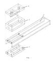
- FIG. 1 represents a schematic view of the various mechanical parts constituting the finger of the robot provided with a force sensor according to the present invention.
- FIG. 2 represents a side view of the finger of a robot fitted with a sensor according to the present invention.
- FIG. 3 represents a view from below of the sensor according to the present invention in a preferred embodiment.
- Figure 4 shows schematically the configuration of the complete detection system comprising a force sensor according to the present invention disposed on the robot's finger.
- the finger 1 of the robot is in the form of a U-shaped aluminum beam in which is disposed a pad 3 of hollow rubber.
- Eight phototransistor detection devices C0 to C7 are placed inside the rubber pad 3 and are fixed to an epoxy printed circuit board 5.
- a second epoxy plate 7 separates the copper tracks from the aluminum cover 9 closing the back of the finger.
- a calibration phase is necessary to determine the elements of the matrix A. To this end, it suffices to carry out known stress states and to measure the signals of the devices C0 to C7.
- the phototransistor housings have dimensions less than one centimeter. These very small dimensions allow the sensor according to the present invention to be easily placed on the finger of a robot.
- the robot's finger is connected to an analog processing card AN by shielded cable.
- This link can be very long since the robot and the analog card are not necessarily located in the same premises.
- the signals circulating in the cable are amplitude modulated at a frequency of 10 kHz on a very low impedance.
- the analog card AN is connected to an acquisition card AQ placed in a PC computer.
- the cable connecting the analog card AN to the acquisition card AQ should be as short as possible since it carries continuous signals requiring a high signal / noise ratio.
- the rubber must have a sufficient thickness so that one also works in the linearity zone.
- a thickness of approximately 1 cm is chosen so as not to exceed 10% of deformation.
- Rubber also allows, by its generally non-linear behavior, to be able to absorb shocks or possible overloads without damaging the phototransistor devices placed inside the bearing.
- the force sensor according to the present invention therefore makes it possible to obtain a sufficiently precise measurement of the tensor of the stresses exerted on the finger of a robot allow the latter to perform high-precision assembly work.
- the originality of the sensor according to the present invention is therefore to carry out a precise and reliable measurement even at the level of contact with the object manipulated, which brings the system closer to human perception and also makes it possible to solve the gripping problem in particular limitation tightening the clamp on the object, slip detection, ...
- the senor is advantageously made in a compact manner, it is light and has small dimensions. In addition, its price is very and its performance allows it to be used on robots performing high-precision assembly tasks, including in disturbed environments.
Abstract
Description
La présente invention concerne un capteur de force notamment destiné à être utilisé sur un robot.The present invention relates to a force sensor intended in particular for use on a robot.
La présente invention concerne également l'utilisation particulière d'un tel capteur sur un robot.The present invention also relates to the particular use of such a sensor on a robot.
On a toujours eu tendance à développer le sens tactile des robots en vue de les destiner plus particulièrement à des travaux d'assemblage qui exigent une grande souplesse et habilité.There has always been a tendency to develop the tactile sense of robots in order to specifically target them for assembly work which requires great flexibility and skill.
Actuellement il existe essentiellement deux grandes catégories de dispositifs qui mesurent les forces d'interaction entre le robot et le monde extérieur permettant aux robots d'avoir une certaine perception au niveau de l'environnement.Currently there are essentially two main categories of devices that measure the interaction forces between the robot and the outside world allowing robots to have a certain perception of the environment.
D'une part, on connaît des dispositifs qui se situent au niveau du poignet reliant la pince de préhension au membre du robot. Ces dispositifs peuvent travailler selon différents principes physiques.On the one hand, devices are known which are located at the wrist connecting the gripper to the member of the robot. These devices can work according to different physical principles.
Un type particulier de capteurs est constitué par des dispositifs dits optiques qui permettent de mesurer des déformations au moyen de détecteurs de lumière à deux dimensions.A particular type of sensor is constituted by so-called optical devices which make it possible to measure deformations by means of two-dimensional light detectors.
Les jauges de contrainte sont également des dispositifs qui permettent d'obtenir une information concernant les forces exercées sur le doigt du robot.The strain gauges are also devices which make it possible to obtain information concerning the forces exerted on the finger of the robot.
Cependant, tous les capteurs décrits ci-dessus sont disposés au niveau du poignet du fait de leur taille relativement importante, ce qui induit toujours une perte d'information par rapport à l'endroit où se produit le contact.However, all the sensors described above are arranged at the wrist because of their size. relatively large, which always results in a loss of information compared to where the contact occurs.
Une autre grande catégorie de capteurs est constituée par les peaux dites artificielles qui fonctionnent selon des principes fort différents, notamment les peaux piézoélectriques, résistives, magnéto-résistives, magnétostrictives, électro-optiques,...Another large category of sensors is constituted by so-called artificial skins which operate according to very different principles, in particular piezoelectric, resistive, magneto-resistive, magnetostrictive, electro-optical skins, etc.
Ces capteurs sont situés en général sur la pince ou sur le doigt de préhension du robot et se présentent sous la forme d'une matrice donnant une information de type ON/OFF. Les peaux artificielles sont principalement destinées à la reconnaissance de forme et ne permettent pas d'obtenir une mesure quantitative précise des forces auxquelles elles sont soumises.These sensors are generally located on the gripper or on the robot's gripping finger and are in the form of a matrix giving information of the ON / OFF type. Artificial skins are mainly intended for shape recognition and do not allow precise quantitative measurement of the forces to which they are subjected.
En outre, certains types de peaux artificielles par exemple les peaux magnéto-résistives subissent l'influence du champ magnétique extérieur.In addition, certain types of artificial skin, for example magneto-resistive skin, are influenced by the external magnetic field.
En outre ce type de capteurs appelés peaux artificielles est particulièrement délicat et ne présente pas une robustesse suffisante leur permettant de résister aux différents chocs se produisant lors du contact direct avec une pièce prise par les doigts du robot.In addition, this type of sensor called artificial skin is particularly delicate and does not have sufficient robustness allowing them to withstand the various shocks occurring during direct contact with a part taken by the robot's fingers.
La demande de brevet EP-0 210 717 décrit un capteur de force à six composantes (Fx, Fy, Fz, Mx, My, Mz) utilisant un matériau déformable de type élastomère et destiné à être intégré à la pince d'un robot.Patent application EP-0 210 717 describes a force sensor with six components (Fx, Fy, Fz, Mx, My, Mz) using a deformable material of the elastomer type and intended to be integrated into the clamp of a robot.
Ce capteur de force utilise la mesure du temps de propagation d'une onde ultrasonique entre un émetteur piézoélectrique, une surface réfléchissante, et un récepteur piézo-électrique. Tout autre signal, notamment un signal optique, capable d'être transmis, réfléchi et détecté peut également être utilisé.This force sensor uses the measurement of the propagation time of an ultrasonic wave between a piezoelectric transmitter, a reflecting surface, and a piezoelectric receiver. Any other signal, in particular an optical signal, capable of being transmitted, reflected and detected can also be used.
Cependant, dans l'espace réduit d'un tel capteur, il est difficile d'introduire les appareils de mesure du temps de propagation d'un signal optique.However, in the reduced space of such a sensor, it is difficult to introduce the devices for measuring the propagation time of an optical signal.
Le brevet US-3 921 445 décrit un capteur de force à six composantes, qui en raison de ses grandes dimensions est destiné à être utilisé entre le bras et la pince (ou l'effecteur) d'un robot.US Patent 3,921,445 describes a six-component force sensor, which due to its large dimensions is intended to be used between the arm and the gripper (or the effector) of a robot.
Ce capteur de force utilise une mesure de l'intensité lumineuse modulée par l'obturation de l'espace de propagation par un cylindre ou une fenêtre placée entre la source lumineuse et le déflecteur, ceux-ci restant fixes l'un par rapport à l'autre. On mesure ainsi le déplacement de ce cylindre ou de cette fenêtre.This force sensor uses a measurement of the light intensity modulated by the closure of the propagation space by a cylinder or a window placed between the light source and the deflector, the latter remaining fixed one relative to the 'other. The displacement of this cylinder or of this window is thus measured.
Cependant, la qualité de ce type de mesure de variation d'intensité lumineuse dépend de l'uniformité de la tache de lumière fournie par l'émetteur et de la faible variation de sensibilité du récepteur.However, the quality of this type of measurement of variation in light intensity depends on the uniformity of the spot of light provided by the transmitter and on the small variation in sensitivity of the receiver.
Or, dans ce type de capteur de force, la qualité de l'uniformité d'émission du signal lumineux est en général médiocre et la variation de la sensibilité du dispositif de réception de ce signal lumineux est trop élevée pour pouvoir obtenir des mesures fiables et reproductibles, quelles que soient les conditions extérieures dans lesquelles le capteur de force est utilisé.However, in this type of force sensor, the quality of the uniformity of emission of the light signal is generally poor and the variation in the sensitivity of the device for receiving this light signal is too high to be able to obtain reliable measurements and reproducible, regardless of the external conditions in which the force sensor is used.
La présente invention vise à proposer un capteur de forces qui permet une mesure des six composantes du tenseur des contraintes à la surface du capteur, c'est-à-dire à l'endroit où le contact se produit.The present invention aims to propose a force sensor which allows a measurement of the six components of the stress tensor at the surface of the sensor, that is to say at the place where contact occurs.
La présente invention vise par conséquent à fournir un capteur qui effectue une mesure quantitative des forces d'interaction entre le capteur et l'environnement extérieur.The present invention therefore aims to provide a sensor which performs a quantitative measurement of the interaction forces between the sensor and the external environment.
Un autre but de la présente invention est de fournir un capteur de force qui présente une taille réduite.Another object of the present invention is to provide a force sensor which has a reduced size.
Le capteur selon la présente invention devra également présenter des qualités de robustesse suffisantes de manière à ce qu'il puisse supporter sans dommage des chocs éventuels exercés sur le doigt ainsi que les surcharges auxquelles il pourrait être soumis.The sensor according to the present invention will also have to have sufficient robustness qualities so that it can withstand without damage any shocks exerted on the finger as well as the overloads to which it could be subjected.
D'autre part, il convient que le capteur soit insensible ou très peu influencé par les conditions extérieures dans lesquelles il sera utilisé, en particulier au champ électro-magnétique intense ou à la radioactivité, à la variation de température ou de lumière, à la poussière et à l'humidité,...On the other hand, the sensor should be insensitive or very little influenced by the external conditions in which it will be used, in particular to the intense electromagnetic field or to radioactivity, to the variation of temperature or light, dust and humidity, ...
Un but complémentaire de la présente invention consiste à fournir un capteur de force qui soit indépendant de la variation de la qualité de l'uniformité d'émission de la lumière et de la variation de la sensibilité du dispositif de réception de ce signal lumineux.An additional aim of the present invention consists in providing a force sensor which is independent of the variation in the quality of the uniformity of light emission and in the variation of the sensitivity of the device for receiving this light signal.
La présente invention se rapporte à un capteur de force essentiellement constitué d'un coussinet en caoutchouc creux dans lequel est disposé au moins un dispositif de détection à phototransistors.The present invention relates to a force sensor essentially consisting of a hollow rubber pad in which is arranged at least one detection device with phototransistors.
Le capteur de force est en réalité un capteur de déplacement qui détecte le déplacement d'une surface lorsque celle-ci est soumise à une force.The force sensor is actually a displacement sensor which detects the displacement of a surface when it is subjected to a force.
Le dispositif à phototransistor comporte dans un boîtier de très petite taille une LED (Light Emission Device), infrarouge, et un phototransistor qui détecte la présence d'une surface devant lui, par la mesure de l'intensité du rayonnement réfléchi sur la surface.The phototransistor device includes, in a very small box, an infrared LED (Light Emission Device) and a phototransistor which detects the presence of a surface in front of it, by measuring the intensity of the radiation reflected on the surface.
De préférence, le capteur de force est destiné à mesurer les six composantes du tenseur des contraintes, à savoir un effort normal, deux efforts tranchants et trois couples, ceci à l'aide de huit dispositifs à phototransistor.Preferably, the force sensor is intended to measure the six components of the stress tensor, namely a normal force, two cutting forces and three torques, this using eight phototransistor devices.
Ce capteur de force est disposé directement sur le doigt du robot ce qui permet d'obtenir une information directe et précise du tenseur des contraintes exercées sur le doigt du robot.This force sensor is placed directly on the robot's finger which makes it possible to obtain direct and precise information from the tensor of the stresses exerted on the robot's finger.
La figure 1 représente une vue schématique des différentes parties mécaniques constituant le doigt du robot muni d'un capteur de force selon la présente invention.FIG. 1 represents a schematic view of the various mechanical parts constituting the finger of the robot provided with a force sensor according to the present invention.
La figure 2 représente une vue par le côté du doigt d'un robot muni d'un capteur selon la présente invention.FIG. 2 represents a side view of the finger of a robot fitted with a sensor according to the present invention.
La figure 3 représente une vue par le dessous du capteur selon la présente invention dans une forme d'exécution préférée.FIG. 3 represents a view from below of the sensor according to the present invention in a preferred embodiment.
La figure 4 représente de manière schématique la configuration du système de détection complet comprenant un capteur de force selon la présente invention disposé sur le doigt du robot.Figure 4 shows schematically the configuration of the complete detection system comprising a force sensor according to the present invention disposed on the robot's finger.
Ainsi que représenté à la figure 1, le doigt 1 du robot se présente sous la forme d'une poutrelle d'aluminium en U sous laquelle est disposé un coussinet 3 en caoutchouc creux. Huit dispositifs de détection à phototransistor C₀ à C₇ sont placés à l'intérieur du coussinet 3 en caoutchouc et sont fixés sur une plaquette 5 de circuit imprimé en époxy. Une seconde plaquette 7 d'époxy sépare les pistes de cuivre du couvercle 9 en aluminium refermant l'arrière du doigt.As shown in Figure 1, the
Selon une forme d'exécution particulière représentée aux figures 2 et 3, les huit dispositifs de détection C₀ à C₇ vont permettre de mesurer les six composantes du tenseur de la manière suivante:
- l'effort normal:

- l'effort tranchant d'axe transversal au doigt:

- l'effort tranchant d'axe parallèle au doigt:

- le couple d'axe normal au doigt:

- le couple d'axe transversal au doigt:

- le couple d'axe parallèle au doigt:

ou de manière matricielle:

soit F = A.CAccording to a particular embodiment represented in FIGS. 2 and 3, the eight detection devices C₀ to C₇ will make it possible to measure the six components of the tensor as follows:
- normal effort:
- the shear force of transverse axis with the finger:
- the shear force of axis parallel to the finger:
- the normal axis torque on the finger:
- the torque of the transverse axis to the finger:
- the axis torque parallel to the finger:
or in a matrix manner:
let F = AC
Une phase d'étalonnage est nécessaire pour déterminer les éléments de la matrice A. A cet effet, il suffit de réaliser des états de contraintes connus et de mesurer les signaux des dispositifs C₀ à C₇.A calibration phase is necessary to determine the elements of the matrix A. To this end, it suffices to carry out known stress states and to measure the signals of the devices C₀ to C₇.
Selon la forme d'exécution préféré représentée aux figures 1 à 3, on citer à titre d'exemple les dimensions suivantes:
- hauteur totale du capteur:
- 25 mm
- largeur totale du capteur:
- 25 mm
- longueur totale du capteur:
- 35 mm.
- total height of the sensor:
- 25 mm
- total width of the sensor:
- 25 mm
- total length of the sensor:
- 35 mm.
Les boîtiers des phototransistors présentent des dimensions inférieures au centimètre. Ces dimensions très faibles permettent de disposer aisément le capteur selon la présente invention sur le doigt d'un robot.The phototransistor housings have dimensions less than one centimeter. These very small dimensions allow the sensor according to the present invention to be easily placed on the finger of a robot.
A la figure 4, le doigt du robot est relié à une carte de traitement analogique AN par câble blindé. Cette liaison peut être très longue puisque le robot et la carte analogique ne sont pas nécessairement situés dans les mêmes locaux. Les signaux circulant dans le câble sont modulés en amplitude à une fréquence de 10 kHz sur une impédance très faible. Ces précautions permettent une grande longueur de câble dans un milieu très perturbé.In FIG. 4, the robot's finger is connected to an analog processing card AN by shielded cable. This link can be very long since the robot and the analog card are not necessarily located in the same premises. The signals circulating in the cable are amplitude modulated at a frequency of 10 kHz on a very low impedance. These precautions allow a long cable length in a highly disturbed environment.
La carte analogique AN est reliée à une carte d'acquisition AQ placée dans un ordinateur PC.The analog card AN is connected to an acquisition card AQ placed in a PC computer.
Le câble reliant la carte analogique AN à la carte d'acquisition AQ devra être aussi court que possible puisqu'il transporte des signaux continus exigeant un rapport signal/bruit élevé.The cable connecting the analog card AN to the acquisition card AQ should be as short as possible since it carries continuous signals requiring a high signal / noise ratio.
La carte analogique a pour but la démodulation et la mise en forme des signaux ainsi que de supprimer l'effet des perturbations extérieures et d'améliorer au maximum les caractéristiques des différents dispositifs de détectionsThe purpose of the analog card is to demodulate and signal shaping as well as eliminating the effect of external disturbances and improving the characteristics of the various detection devices as much as possible
En effet, ceux-ci sont normalement congrus pour un fonctionnement en tout ou rien, mais leur courbe de réponse présente une partie à peu près linéaire pour des distances phototransistor-surface variant entre 1 et 2 mm.Indeed, these are normally congruent for all-or-nothing operation, but their response curve has an approximately linear part for phototransistor-surface distances varying between 1 and 2 mm.
Ceci est mis à profit pour obtenir une mesure quantitative du tenseur des contraintes.This is used to obtain a quantitative measure of the stress tensor.
En outre, le caoutchouc devra présenter une épaisseur suffisante de manière à ce que l'on travaille également dans la zone de linéarité. En particulier, on choisit une épaisseur d'environ 1 cm de manière à ne pas dépasser 10% de déformation.In addition, the rubber must have a sufficient thickness so that one also works in the linearity zone. In particular, a thickness of approximately 1 cm is chosen so as not to exceed 10% of deformation.
Le caoutchouc permet également, par son comportement globalement non linéaire, de pouvoir encaisser les chocs ou les surcharges éventuels sans détériorer les dispositifs à phototransistor placés à l'intérieur du coussinet.Rubber also allows, by its generally non-linear behavior, to be able to absorb shocks or possible overloads without damaging the phototransistor devices placed inside the bearing.
Le capteur de force selon la présente invention permet par conséquent d'obtenir une mesure suffisamment précise du tenseur des contraintes exercées sur le doigt d'un robot permettent à ce dernier d'effectuer des travaux d'assemblage de haute précision.The force sensor according to the present invention therefore makes it possible to obtain a sufficiently precise measurement of the tensor of the stresses exerted on the finger of a robot allow the latter to perform high-precision assembly work.
En particulier, on a pu obtenir des sensibilités de l'ordre de:
- FX:
- 0,5 N
- FY:
- 0,1 N
- FZ:
- 0,1 N
- MX:
- 0,001 Nm
- MY:
- 0,001 Nm
- MZ:
- 0,001 Nm
- FX:
- 0.5 N
- FY:
- 0.1 N
- FZ:
- 0.1 N
- MX:
- 0.001 Nm
- MY:
- 0.001 Nm
- MZ:
- 0.001 Nm
L'originalité du capteur selon la présente invention est donc de réaliser une mesure précise et fiable au niveau même du contact avec l'objet manipulé, ce qui rapproche le système de la perception humaine et permet également de résoudre le problème de préhension en particulier limitation du serrage de la pince sur l'objet, détection du glissement,...The originality of the sensor according to the present invention is therefore to carry out a precise and reliable measurement even at the level of contact with the object manipulated, which brings the system closer to human perception and also makes it possible to solve the gripping problem in particular limitation tightening the clamp on the object, slip detection, ...
Le capteur est avantageusement réalisé de manière compacte, il est léger et présente de faibles dimensions. En outre, son prix est dérisoire et ses performances permettent de l'utiliser sur des robots effectuant des tâches d'assemblage de haute précision, y compris dans des milieux perturbés.The sensor is advantageously made in a compact manner, it is light and has small dimensions. In addition, its price is ridiculous and its performance allows it to be used on robots performing high-precision assembly tasks, including in disturbed environments.
Claims (6)
Applications Claiming Priority (2)
| Application Number | Priority Date | Filing Date | Title |
|---|---|---|---|
| BE9100588A BE1004980A3 (en) | 1991-06-18 | 1991-06-18 | Force sensor and use thereof on a robot. |
| BE9100588 | 1991-06-18 |
Publications (2)
| Publication Number | Publication Date |
|---|---|
| EP0523031A1 true EP0523031A1 (en) | 1993-01-13 |
| EP0523031B1 EP0523031B1 (en) | 1996-04-24 |
Family
ID=3885574
Family Applications (1)
| Application Number | Title | Priority Date | Filing Date |
|---|---|---|---|
| EP92870091A Expired - Lifetime EP0523031B1 (en) | 1991-06-18 | 1992-06-18 | Multiple-component force sensor and its application on a robot |
Country Status (4)
| Country | Link |
|---|---|
| EP (1) | EP0523031B1 (en) |
| AT (1) | ATE137330T1 (en) |
| BE (1) | BE1004980A3 (en) |
| DE (1) | DE69210122T2 (en) |
Cited By (2)
| Publication number | Priority date | Publication date | Assignee | Title |
|---|---|---|---|---|
| WO2017200495A1 (en) | 2016-05-16 | 2017-11-23 | Koc Universitesi | Artificial hand having finger units provided with a photo coupler contact force sensor |
| WO2022188218A1 (en) * | 2021-03-09 | 2022-09-15 | 中国科学院自动化研究所 | Multi-dimensional force sensor |
Families Citing this family (1)
| Publication number | Priority date | Publication date | Assignee | Title |
|---|---|---|---|---|
| DE102005063022B4 (en) * | 2005-12-30 | 2013-05-29 | Deutsches Zentrum für Luft- und Raumfahrt e.V. | Opto-electronic force-moment sensor |
Citations (2)
| Publication number | Priority date | Publication date | Assignee | Title |
|---|---|---|---|---|
| US3921445A (en) * | 1973-10-15 | 1975-11-25 | Stanford Research Inst | Force and torque sensing method and means for manipulators and the like |
| EP0210717A2 (en) * | 1985-07-22 | 1987-02-04 | Bonneville Scientific, Inc. | A sensor for and process of detecting and quantifying force-torque components |
-
1991
- 1991-06-18 BE BE9100588A patent/BE1004980A3/en not_active IP Right Cessation
-
1992
- 1992-06-18 AT AT92870091T patent/ATE137330T1/en not_active IP Right Cessation
- 1992-06-18 DE DE69210122T patent/DE69210122T2/en not_active Expired - Fee Related
- 1992-06-18 EP EP92870091A patent/EP0523031B1/en not_active Expired - Lifetime
Patent Citations (2)
| Publication number | Priority date | Publication date | Assignee | Title |
|---|---|---|---|---|
| US3921445A (en) * | 1973-10-15 | 1975-11-25 | Stanford Research Inst | Force and torque sensing method and means for manipulators and the like |
| EP0210717A2 (en) * | 1985-07-22 | 1987-02-04 | Bonneville Scientific, Inc. | A sensor for and process of detecting and quantifying force-torque components |
Cited By (2)
| Publication number | Priority date | Publication date | Assignee | Title |
|---|---|---|---|---|
| WO2017200495A1 (en) | 2016-05-16 | 2017-11-23 | Koc Universitesi | Artificial hand having finger units provided with a photo coupler contact force sensor |
| WO2022188218A1 (en) * | 2021-03-09 | 2022-09-15 | 中国科学院自动化研究所 | Multi-dimensional force sensor |
Also Published As
| Publication number | Publication date |
|---|---|
| DE69210122D1 (en) | 1996-05-30 |
| DE69210122T2 (en) | 1996-11-21 |
| BE1004980A3 (en) | 1993-03-09 |
| ATE137330T1 (en) | 1996-05-15 |
| EP0523031B1 (en) | 1996-04-24 |
Similar Documents
| Publication | Publication Date | Title |
|---|---|---|
| EP1848363B1 (en) | Dental treatment apparatus with automatic insert recognition | |
| EP0222652B1 (en) | Force and torsion measuring device and its application to a tactile sensor or gripping device | |
| US4733068A (en) | Crossed fiber optic tactile sensor | |
| EP2150882B1 (en) | Method for locating a touch on a surface and device for implementing this method | |
| WO1986005273A1 (en) | Optical device for strain detection, method for measuring the strain by means of said device and their application to scales | |
| WO2011015733A2 (en) | Device and method for locating a locally deforming contact on a deformable touch-sensitive surface of an object | |
| EP0974042B1 (en) | Polarimeter and corresponding measuring method | |
| EP2304391B1 (en) | Optical device and method for measuring the rotation of an object | |
| EP2522152A1 (en) | Sound wave detection device and sound wave source location system | |
| EP0523031B1 (en) | Multiple-component force sensor and its application on a robot | |
| FR2956738A1 (en) | DEVICE FOR MEASURING TORSIONS, FLEXIONS OR OTHER DEFORMATIONS AND METHOD FOR MANUFACTURING SUCH A DEVICE | |
| EP2537008A1 (en) | Interactive panel comprising piezoelectric transduction devices | |
| CA2220940C (en) | Device for determining phase faults in electromagnetic waves | |
| EP2659835B1 (en) | Device for quantifying finger independence | |
| US4091681A (en) | Method for the simultaneous determination of low optical bulk and surface absorption coefficients in solids | |
| EP2861977B1 (en) | Non destructive ultrasonic inspection of structures in composite material | |
| EP3173758A1 (en) | System and method for tactile sensing using thin film optical sensing networks | |
| EP1541970B1 (en) | Method for compensating anisotropy in a vibrating bell inertial rotation sensor | |
| EP0246130A1 (en) | Detector for the linear, non-contacting measurement of the distance to a target using scattered radiation | |
| EP3803267B1 (en) | Method and device for evaluating a mechanical property of a material | |
| FR2630536A1 (en) | Device for measuring an angle with respect to a reference plane | |
| WO1990007700A2 (en) | Flexion detecting device | |
| FR3028342A1 (en) | SYSTEM FOR DETECTING THE POSITION AND MOVEMENT OF FINGERS ON A WHEEL | |
| FR2673710A1 (en) | METHOD FOR READING THE SHAPE OF ANY ELASTICALLY DEFORMABLE ARTICLE, ESPECIALLY FOR READING A CIRCLE CONTOUR OR ENCOURAGING A GLASSES FRAME. | |
| EP4038482A1 (en) | System for detecting a path traced by an implement on a writing surface |
Legal Events
| Date | Code | Title | Description |
|---|---|---|---|
| PUAI | Public reference made under article 153(3) epc to a published international application that has entered the european phase |
Free format text: ORIGINAL CODE: 0009012 |
|
| AK | Designated contracting states |
Kind code of ref document: A1 Designated state(s): AT BE CH DE FR GB IT LI LU NL SE |
|
| 17P | Request for examination filed |
Effective date: 19930701 |
|
| 17Q | First examination report despatched |
Effective date: 19941123 |
|
| GRAH | Despatch of communication of intention to grant a patent |
Free format text: ORIGINAL CODE: EPIDOS IGRA |
|
| GRAA | (expected) grant |
Free format text: ORIGINAL CODE: 0009210 |
|
| AK | Designated contracting states |
Kind code of ref document: B1 Designated state(s): AT BE CH DE FR GB IT LI LU NL SE |
|
| PG25 | Lapsed in a contracting state [announced via postgrant information from national office to epo] |
Ref country code: IT Free format text: LAPSE BECAUSE OF FAILURE TO SUBMIT A TRANSLATION OF THE DESCRIPTION OR TO PAY THE FEE WITHIN THE PRE;WARNING: LAPSES OF ITALIAN PATENTS WITH EFFECTIVE DATE BEFORE 2007 MAY HAVE OCCURRED AT ANY TIME BEFORE 2007. THE CORRECT EFFECTIVE DATE MAY BE DIFFERENT FROM THE ONE RECORDED.SCRIBED TIME-LIMIT Effective date: 19960424 Ref country code: AT Effective date: 19960424 |
|
| REF | Corresponds to: |
Ref document number: 137330 Country of ref document: AT Date of ref document: 19960515 Kind code of ref document: T |
|
| REF | Corresponds to: |
Ref document number: 69210122 Country of ref document: DE Date of ref document: 19960530 |
|
| REG | Reference to a national code |
Ref country code: CH Ref legal event code: NV Representative=s name: DIPL.-ING. ETH H. R. WERFFELI PATENTANWALT |
|
| PGFP | Annual fee paid to national office [announced via postgrant information from national office to epo] |
Ref country code: FR Payment date: 19960619 Year of fee payment: 5 |
|
| PGFP | Annual fee paid to national office [announced via postgrant information from national office to epo] |
Ref country code: CH Payment date: 19960621 Year of fee payment: 5 |
|
| PGFP | Annual fee paid to national office [announced via postgrant information from national office to epo] |
Ref country code: BE Payment date: 19960625 Year of fee payment: 5 |
|
| PG25 | Lapsed in a contracting state [announced via postgrant information from national office to epo] |
Ref country code: LU Free format text: LAPSE BECAUSE OF NON-PAYMENT OF DUE FEES Effective date: 19960630 |
|
| PGFP | Annual fee paid to national office [announced via postgrant information from national office to epo] |
Ref country code: NL Payment date: 19960630 Year of fee payment: 5 |
|
| PGFP | Annual fee paid to national office [announced via postgrant information from national office to epo] |
Ref country code: GB Payment date: 19960702 Year of fee payment: 5 |
|
| GBT | Gb: translation of ep patent filed (gb section 77(6)(a)/1977) |
Effective date: 19960614 |
|
| PG25 | Lapsed in a contracting state [announced via postgrant information from national office to epo] |
Ref country code: SE Effective date: 19960724 |
|
| PGFP | Annual fee paid to national office [announced via postgrant information from national office to epo] |
Ref country code: DE Payment date: 19960725 Year of fee payment: 5 |
|
| PLBE | No opposition filed within time limit |
Free format text: ORIGINAL CODE: 0009261 |
|
| STAA | Information on the status of an ep patent application or granted ep patent |
Free format text: STATUS: NO OPPOSITION FILED WITHIN TIME LIMIT |
|
| 26N | No opposition filed | ||
| PG25 | Lapsed in a contracting state [announced via postgrant information from national office to epo] |
Ref country code: GB Free format text: LAPSE BECAUSE OF NON-PAYMENT OF DUE FEES Effective date: 19970618 |
|
| PG25 | Lapsed in a contracting state [announced via postgrant information from national office to epo] |
Ref country code: LI Free format text: LAPSE BECAUSE OF NON-PAYMENT OF DUE FEES Effective date: 19970630 Ref country code: CH Free format text: LAPSE BECAUSE OF NON-PAYMENT OF DUE FEES Effective date: 19970630 Ref country code: BE Effective date: 19970630 |
|
| BERE | Be: lapsed |
Owner name: UNIVERSITE LIBRE DE BRUXELLES Effective date: 19970630 |
|
| PG25 | Lapsed in a contracting state [announced via postgrant information from national office to epo] |
Ref country code: NL Effective date: 19980101 |
|
| GBPC | Gb: european patent ceased through non-payment of renewal fee |
Effective date: 19970618 |
|
| REG | Reference to a national code |
Ref country code: CH Ref legal event code: PL |
|
| PG25 | Lapsed in a contracting state [announced via postgrant information from national office to epo] |
Ref country code: FR Free format text: LAPSE BECAUSE OF NON-PAYMENT OF DUE FEES Effective date: 19980227 |
|
| NLV4 | Nl: lapsed or anulled due to non-payment of the annual fee |
Effective date: 19980101 |
|
| PG25 | Lapsed in a contracting state [announced via postgrant information from national office to epo] |
Ref country code: DE Free format text: LAPSE BECAUSE OF NON-PAYMENT OF DUE FEES Effective date: 19980303 |
|
| REG | Reference to a national code |
Ref country code: FR Ref legal event code: ST |
|
| REG | Reference to a national code |
Ref country code: FR Ref legal event code: ST |