EP0522657A1 - Control circuit for a direct current/three-phase current converter - Google Patents
Control circuit for a direct current/three-phase current converter Download PDFInfo
- Publication number
- EP0522657A1 EP0522657A1 EP92202076A EP92202076A EP0522657A1 EP 0522657 A1 EP0522657 A1 EP 0522657A1 EP 92202076 A EP92202076 A EP 92202076A EP 92202076 A EP92202076 A EP 92202076A EP 0522657 A1 EP0522657 A1 EP 0522657A1
- Authority
- EP
- European Patent Office
- Prior art keywords
- current
- direct
- converter
- angle
- synchronous machine
- Prior art date
- Legal status (The legal status is an assumption and is not a legal conclusion. Google has not performed a legal analysis and makes no representation as to the accuracy of the status listed.)
- Withdrawn
Links
Images


Classifications
-
- H—ELECTRICITY
- H02—GENERATION; CONVERSION OR DISTRIBUTION OF ELECTRIC POWER
- H02P—CONTROL OR REGULATION OF ELECTRIC MOTORS, ELECTRIC GENERATORS OR DYNAMO-ELECTRIC CONVERTERS; CONTROLLING TRANSFORMERS, REACTORS OR CHOKE COILS
- H02P25/00—Arrangements or methods for the control of AC motors characterised by the kind of AC motor or by structural details
- H02P25/02—Arrangements or methods for the control of AC motors characterised by the kind of AC motor or by structural details characterised by the kind of motor
- H02P25/022—Synchronous motors
- H02P25/03—Synchronous motors with brushless excitation
-
- B—PERFORMING OPERATIONS; TRANSPORTING
- B60—VEHICLES IN GENERAL
- B60L—PROPULSION OF ELECTRICALLY-PROPELLED VEHICLES; SUPPLYING ELECTRIC POWER FOR AUXILIARY EQUIPMENT OF ELECTRICALLY-PROPELLED VEHICLES; ELECTRODYNAMIC BRAKE SYSTEMS FOR VEHICLES IN GENERAL; MAGNETIC SUSPENSION OR LEVITATION FOR VEHICLES; MONITORING OPERATING VARIABLES OF ELECTRICALLY-PROPELLED VEHICLES; ELECTRIC SAFETY DEVICES FOR ELECTRICALLY-PROPELLED VEHICLES
- B60L50/00—Electric propulsion with power supplied within the vehicle
- B60L50/30—Electric propulsion with power supplied within the vehicle using propulsion power stored mechanically, e.g. in fly-wheels
-
- B—PERFORMING OPERATIONS; TRANSPORTING
- B60—VEHICLES IN GENERAL
- B60L—PROPULSION OF ELECTRICALLY-PROPELLED VEHICLES; SUPPLYING ELECTRIC POWER FOR AUXILIARY EQUIPMENT OF ELECTRICALLY-PROPELLED VEHICLES; ELECTRODYNAMIC BRAKE SYSTEMS FOR VEHICLES IN GENERAL; MAGNETIC SUSPENSION OR LEVITATION FOR VEHICLES; MONITORING OPERATING VARIABLES OF ELECTRICALLY-PROPELLED VEHICLES; ELECTRIC SAFETY DEVICES FOR ELECTRICALLY-PROPELLED VEHICLES
- B60L2220/00—Electrical machine types; Structures or applications thereof
- B60L2220/10—Electrical machine types
- B60L2220/14—Synchronous machines
-
- Y—GENERAL TAGGING OF NEW TECHNOLOGICAL DEVELOPMENTS; GENERAL TAGGING OF CROSS-SECTIONAL TECHNOLOGIES SPANNING OVER SEVERAL SECTIONS OF THE IPC; TECHNICAL SUBJECTS COVERED BY FORMER USPC CROSS-REFERENCE ART COLLECTIONS [XRACs] AND DIGESTS
- Y02—TECHNOLOGIES OR APPLICATIONS FOR MITIGATION OR ADAPTATION AGAINST CLIMATE CHANGE
- Y02T—CLIMATE CHANGE MITIGATION TECHNOLOGIES RELATED TO TRANSPORTATION
- Y02T10/00—Road transport of goods or passengers
- Y02T10/60—Other road transportation technologies with climate change mitigation effect
- Y02T10/64—Electric machine technologies in electromobility
-
- Y—GENERAL TAGGING OF NEW TECHNOLOGICAL DEVELOPMENTS; GENERAL TAGGING OF CROSS-SECTIONAL TECHNOLOGIES SPANNING OVER SEVERAL SECTIONS OF THE IPC; TECHNICAL SUBJECTS COVERED BY FORMER USPC CROSS-REFERENCE ART COLLECTIONS [XRACs] AND DIGESTS
- Y02—TECHNOLOGIES OR APPLICATIONS FOR MITIGATION OR ADAPTATION AGAINST CLIMATE CHANGE
- Y02T—CLIMATE CHANGE MITIGATION TECHNOLOGIES RELATED TO TRANSPORTATION
- Y02T10/00—Road transport of goods or passengers
- Y02T10/60—Other road transportation technologies with climate change mitigation effect
- Y02T10/70—Energy storage systems for electromobility, e.g. batteries
Definitions
- the invention relates to a control circuit for semiconductor components which can be switched on and off and which form part of a converter circuit for converting direct current into three-phase current, which converter circuit is connected between a direct-current source and the stator of a synchronous machine having a cylindrical rotor, and which control circuit comprises rotor position sensors for sensing the position of the rotor with respect to the stator of the synchronous machine, and also a direct-current measuring device for measuring the value of the direct current.
- the converter circuit containing semiconductor components which can be switched on and off is connected between a direct-current traction machine of a vehicle and a three-phase synchronous machine which is coupled directly to a flywheel and which, like the electrical machines, is situated in the vehicle, and a conversion of electrical energy originating from one of the two machines into a form suitable for the other machine can be achieved using the semiconductor circuit.
- energy can be drawn from the rotating flywheel by electrically slowing down the synchronous machine, coupled thereto, in generator mode and converting the three-phase current generated in this way into direct current with the aid of the semiconductor circuit and feeding said current to the direct-current traction machine in motor mode.
- energy can be drawn from the moving vehicle, which is coupled to the rotating direct-current traction machine in generator mode, for the purpose of decelerating the vehicle by electrically slowing down the direct-current traction machine and converting the direct current generated in this way into three-phase current with the aid of the semiconductor circuit and feeding said current to the synchronous machine in motor mode, which is thereby accelerated and largely stores the energy released in slowing down the vehicle in the flywheel coupled to it.
- the maximum rotational speed chosen for the flywheel is as high as possible in order to be able to store a large amount of energy.
- the rotor, directly coupled to the flywheel, of the synchronous machine, the term "directly coupled" relating in this case to the fact that the rotor of the synchronous machine and the flywheel form a single entity, should therefore also be suitable, in particular from a mechanical point of view, for high rotational speeds.
- Such a rotor is a rotor which is equipped with permanent magnets and which furthermore has the advantageous property that no electrical energy has to be fed thereto for energizing purposes.
- a motor energization can also be achieved in another way.
- both the switch-on time and the switch-off time of every semiconductor component have to be determined by the control circuit.
- a gate holding current has to be supplied during the interval in which a semiconductor component is conducting.
- the switch-off instruction for the first semiconductor component in the case of a purely natural commutation should only be given after the natural commutation to the second semiconductor component has been completed.
- a minimum overlap angle of the control signals during at least the commutation angle ⁇ , when the two semiconductor components are conducting, is necessary to ensure a satisfactory switch-off of the first semiconductor component after the commutation has been completed.
- the above requires a design of a control circuit which ensures the switching-off of the first semiconductor component during the extinction advance angle b.
- a passage of the phase current through zero, which occurs in a phase after completion of the commutation, is detected with the aid of phase-current measuring devices, after which a switch-off instruction is generated in said phase by the control circuit.
- the switch-off angle of the first semiconductor component is greater than 180°, commutation from the second phase back to the first phase will occur. For this reason, forced commutation is necessary, and the overlap angle of the control signals has to be limited to a maximum value of 180° - ⁇ , where ⁇ is the firing angle.
- the object of the invention is to be able to determine the firing angle ⁇ , the commutation angle ⁇ and the load angle h exclusively on the basis of a measurement of the rotor position and the level of the direct current on the direct-current side of the converter for the purpose of controlling the energy conversion.
- the term "direct current” may also relate to a rectified alternating or three-phase current or any other current whatsoever originating from a direct-voltage source.
- control circuit is characterised by computing means which are designed to determine the value of the commutation angle ⁇ of the phase current i in the converter for any value of the direct current on the basis of a model of the synchronous machine which solely takes account of the fundamental harmonic of the phase current, the firing angle ⁇ of the semiconductor components being set between limits (determined for any value of the direct current by the associated commutation angle ⁇ ).
- the range of control for the firing angle ⁇ is thus appreciably widened, in particular for low direct currents.
- the computing means are designed to determine the firing angle ⁇ , the commutation angle ⁇ and the load angle h from a solution of the equations: and where L m and L c are the synchronous inductance and the commutation inductance, respectively, and ⁇ represents a proportionality factor between the angular frequency ⁇ and the armature voltage E of the synchronous machine.
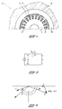
- Fig. 1 shows a synchronous machine 2 having a fixed, essentially cylindrical stator 4 whose outer circumference is provided with stator teeth 6 which form the boundaries of stator grooves 8 containing windings 9.
- the rotor 10 whose inner circumference is provided with a number of poles in the form of permanent magnets 12 is rotatable around the stator 4.
- Mounted at the outer circumference of the rotor 10 is a flywheel body 14.
- Fig. 2 shows a single-phase equivalent diagram of the synchronous machine in which E denotes the armature voltage, I the fundamental harmonic of the current and U' the fundamental harmonic of the virtual phase terminal voltage.
- the resistance of the windings is assumed to be negligibly small.
- the synchronous inductance is represented by L m and the commutation inductance, which is virtually equivalent to the subtransient inductance, by L c .
- the associated phasor diagram is shown in Fig. 3.
- the current I with an angular frequency ⁇ , lags behind the voltage U' by an angle ⁇ .
- the load angle is denoted by ⁇ , while the firing angle for the semiconductor components which switch the current is indicated by ⁇ .
- ⁇ the firing angle for the semiconductor components which switch the current
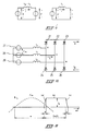
- FIG. 5 diagrammatically shows a portion of a two-way three-phase current/direct-current converter circuit comprising six semiconductor components 21-26.
- the three internal phase voltages on the three-phase current side are represented by alternating-voltage sources 27-29 for the phases U, V and W, respectively.
- one commutation interval for example the one in which commutation takes place from semiconductor component 21 to semiconductor component 22.
- IX current on the direct-current side remains constant during the commutation.
- the current in part (a) is:
- the current in the decreasing part (c) can readily be derived from equation (XIII) with a lag angle 2 ⁇ /3 (at the instant of commutation from phase V to phase W) and subtracting the value I d :
- Substitution of the value of I d derived from equation (XII) yields:
- Fig. 7 shows the variation in a phase current i.
- the variation in the virtual phase voltage u'( ⁇ t) in accordance with equation (IV) is shown for the synchronous machine shown in Fig. 1 with the aid of a broken line. The phase shift ⁇ and the amplitude of the fundamental harmonic of the phase current i indicated with the aid of a chain dotted line will subsequently be calculated.
- Fig. 8 shows the relationship between the angles ⁇ l , ⁇ , ⁇ , ⁇ and ⁇ , the waveform of the virtual terminal voltage u' vu for no-load (broken line) and for loading (continuous line).
- the extinction time of a semiconductor component of a converter should fall within the interval determined by the extinction advance angle ⁇ (see Fig. 8). This ensures that the extinction time does not disturb the commutation or occurs after the time when the terminal voltage reverses.
- the calculated functions can be used to determine the switch-off instant of the semiconductor components in the converter.
- the switching-off of the semiconductor components prior to the polarity reversal of the terminal voltage can be achieved by ensuring that the firing angle ⁇ l is within the interval: ⁇ 1,0 ⁇ ⁇ 1 ⁇ ⁇ 1,180 (XXXI)
- XXXI XXXI
- Fig. 11 shows a diagram for the control of a converter circuit such as that shown in Fig. 5.
- the converter circuit 40 shown here diagrammatically is coupled, on the one hand, to the synchronous machine 2 via three leads 41a - 41c and, on the other hand, to a direct-current traction machine (not shown) via two leads 42a and 42b, to which direct-current traction machine a current I d is delivered by the converter circuit 40.
- a direct-current measuring device 43 measures the value of the current I d and feeds said value via a lead 44 to a comparator 45 in which the value I d actually occurring is compared with a current set value which is supplied via a lead 46.
- the output signal, resulting from the comparison, of the comparator 45 is fed via a lead 47 to computing means 48 in which the angles ⁇ , ⁇ and ⁇ are determined with the aid of the abovementioned output signal on the basis of equations (XXIV), (XXVIII) and (XXIX).
- angles ⁇ , ⁇ and ⁇ can also be calculated in real time during the operation of the converter if one or more sufficiently fast processors is or are incorporated in the computing means.
- the firing angle ⁇ is fed via a lead 49 to a pulse sequence control circuit 50 to which a rotor position measurement signal originating from a rotor position sensor 52 is also fed via a lead 51, which rotor position sensor 52 senses the position of the rotor of the synchronous machine 2 with respect to its stator.
- a pulse sequence control circuit 50 gate control pulses are then formed for each semiconductor component to be controlled and transmitted to the converter circuit 40 via leads 53a - 53f.
- the pulse sequence control circuit 50 comprises counters known per se into which the start time and the duration of each gate control pulse can be loaded.
Abstract
Control circuit for semiconductor components (21-26) of a converter circuit (40) which can be switched on and off to convert direct current (Id) into three-phase current. The converter circuit is connected between a direct-current source and the stator of a synchronous machine (2) having a cylindrical rotor. The control circuit comprises rotor position sensors (52) and also a direct current measuring device (43). The control circuit comprises a computer which is designed to determine the value of the commutation angle (µ) of the phase current (i) in the converter at any value of the direct current (Id) on the basis of a model of the synchronous machine (2) which solely takes account of the fundamental harmonic of the phase current (i), the firing angle (α) of the semiconductor components being set between limits determined for any value of the direct current (Id) by the associated commutation angle (µ).
Description
- The invention relates to a control circuit for semiconductor components which can be switched on and off and which form part of a converter circuit for converting direct current into three-phase current, which converter circuit is connected between a direct-current source and the stator of a synchronous machine having a cylindrical rotor, and which control circuit comprises rotor position sensors for sensing the position of the rotor with respect to the stator of the synchronous machine, and also a direct-current measuring device for measuring the value of the direct current.
- In a specific application, the converter circuit containing semiconductor components which can be switched on and off is connected between a direct-current traction machine of a vehicle and a three-phase synchronous machine which is coupled directly to a flywheel and which, like the electrical machines, is situated in the vehicle, and a conversion of electrical energy originating from one of the two machines into a form suitable for the other machine can be achieved using the semiconductor circuit. In this way, to accelerate the vehicle, energy can be drawn from the rotating flywheel by electrically slowing down the synchronous machine, coupled thereto, in generator mode and converting the three-phase current generated in this way into direct current with the aid of the semiconductor circuit and feeding said current to the direct-current traction machine in motor mode. Conversely, energy can be drawn from the moving vehicle, which is coupled to the rotating direct-current traction machine in generator mode, for the purpose of decelerating the vehicle by electrically slowing down the direct-current traction machine and converting the direct current generated in this way into three-phase current with the aid of the semiconductor circuit and feeding said current to the synchronous machine in motor mode, which is thereby accelerated and largely stores the energy released in slowing down the vehicle in the flywheel coupled to it.
- Although the energy losses in this arrangement, primarily in the form of frictional losses as a result of the movement of the vehicle, frictional losses in the flywheel bearing and electrical losses in the machines and the converter circuit have to be regularly compensated for, for example by feeding electrical energy from outside the vehicle in a form which is directly suitable for driving the direct-current traction machine or the synchronous machine, or is suitable for that purpose after a conversion in the converter circuit or a converter of this type, the outlined combination of flywheel, synchronous machine, converter and direct-current traction machine and the outlined use thereof produces a particularly energy-efficient vehicle drive system.
- The maximum rotational speed chosen for the flywheel is as high as possible in order to be able to store a large amount of energy. The rotor, directly coupled to the flywheel, of the synchronous machine, the term "directly coupled" relating in this case to the fact that the rotor of the synchronous machine and the flywheel form a single entity, should therefore also be suitable, in particular from a mechanical point of view, for high rotational speeds. Such a rotor is a rotor which is equipped with permanent magnets and which furthermore has the advantageous property that no electrical energy has to be fed thereto for energizing purposes. However, a motor energization can also be achieved in another way.
- In relatively short-cycle applications such as those, for example, in which the vehicle described above has a public transport function, there is the need to convert an appreciable amount of electrical energy into mechanical energy and vice versa within a short period of time. This imposes high requirements on the control of the converter which, with the high current frequencies and voltage frequencies prevailing within the entire rotational speed range of the flywheel, but in particular within the normal operating range thereof, always has to be capable of reliably converting as large an electric power as possible, given the maximum loading capacities of the electrical machines coupled thereto.
- Another application of a converter as described above is seen in an uninterrupted electrical power supply which can absorb temporary interruptions in the mains voltage.
- In a converter circuit comprising at least six semiconductor components which can be switched on and off for the purpose of a two-way three-phase conversion, both the switch-on time and the switch-off time of every semiconductor component have to be determined by the control circuit. In addition, a gate holding current has to be supplied during the interval in which a semiconductor component is conducting.
- If a direct current commutates between a first and a second semiconductor component, the switch-off instruction for the first semiconductor component in the case of a purely natural commutation should only be given after the natural commutation to the second semiconductor component has been completed. A minimum overlap angle of the control signals during at least the commutation angle µ, when the two semiconductor components are conducting, is necessary to ensure a satisfactory switch-off of the first semiconductor component after the commutation has been completed.
- The above requires a design of a control circuit which ensures the switching-off of the first semiconductor component during the extinction advance angle b. For this purpose in a conventional converter circuit a passage of the phase current through zero, which occurs in a phase after completion of the commutation, is detected with the aid of phase-current measuring devices, after which a switch-off instruction is generated in said phase by the control circuit.
- If the switch-off angle of the first semiconductor component is greater than 180°, commutation from the second phase back to the first phase will occur. For this reason, forced commutation is necessary, and the overlap angle of the control signals has to be limited to a maximum value of 180° - α, where α is the firing angle.
- For a particular combination of a synchronous machine, direct-current source and converter, the object of the invention is to be able to determine the firing angle α, the commutation angle µ and the load angle h exclusively on the basis of a measurement of the rotor position and the level of the direct current on the direct-current side of the converter for the purpose of controlling the energy conversion. In this connection, the term "direct current" may also relate to a rectified alternating or three-phase current or any other current whatsoever originating from a direct-voltage source.
- To reach this aim the control circuit according to the invention is characterised by computing means which are designed to determine the value of the commutation angle µ of the phase current i in the converter for any value of the direct current on the basis of a model of the synchronous machine which solely takes account of the fundamental harmonic of the phase current, the firing angle α of the semiconductor components being set between limits (determined for any value of the direct current by the associated commutation angle µ). The range of control for the firing angle α is thus appreciably widened, in particular for low direct currents.
- In a preferred embodiment, the computing means are designed to determine the firing angle α, the commutation angle µ and the load angle h from a solution of the equations:

and
where Lm and Lc are the synchronous inductance and the commutation inductance, respectively, and Φ represents a proportionality factor between the angular frequency ω and the armature voltage E of the synchronous machine. - The invention is explained by reference to the drawing, in which:
- Fig. 1 shows a diagrammatic partial cross section of a synchronous machine with an inner stator and an outer permanent magnet rotor;
- Fig. 2 shows a single-phase electrical equivalent diagram of the machine shown in Fig. 1;
- Fig. 3 shows the phasor diagram associated with the equivalent diagram shown in Fig. 2;
- Fig. 4 shows the equivalent diagram shown in Fig. 2, which has been augmented with a circuit for describing the behaviour of the synchronous machine during commutation of a current flowing therein in a converter circuit coupled thereto;
- Fig. 5 shows an electrical diagram of a converter circuit coupled to the synchronous machine;
- Fig. 6 shows a portion of the waveform of the phase current iv in the converter circuit shown in Fig. 5;
- Fig. 7 again shown a portion of the waveform of a phase current i in the converter circuit according to Fig. 5;
- Fig. 8 serves to illustrate the mutual relationships between the various angles;
- Fig. 9 shows the relationship between the direct current Id on the direct-current side of the converter circuit and the maximum value of the commutation angle for a particular circuit configuration;
- Fig. 10 shows the relationship between the limit values of the firing angle and the direct current Id for the circuit configuration on which Fig. 9 is based, and
- Fig. 11 diagrammatically shows the control of the converter circuit.
- Hereinafter parts and quantities indicated by identical reference symbols in different figures have the same meaning.
- Fig. 1 shows a
synchronous machine 2 having a fixed, essentiallycylindrical stator 4 whose outer circumference is provided withstator teeth 6 which form the boundaries ofstator grooves 8 containingwindings 9. Therotor 10 whose inner circumference is provided with a number of poles in the form ofpermanent magnets 12 is rotatable around thestator 4. Mounted at the outer circumference of therotor 10 is aflywheel body 14. - To describe the behaviour of the direct-current/three-phase current converter when interacting with the permanent magnet machine, use will be made of a simplified equivalent diagram such as is known as a model for the steady state of a synchronous machine having a cylindrical rotor, without the commutation inductance of the machine.
- Fig. 2 shows a single-phase equivalent diagram of the synchronous machine in which E denotes the armature voltage, I the fundamental harmonic of the current and U' the fundamental harmonic of the virtual phase terminal voltage. The resistance of the windings is assumed to be negligibly small. The synchronous inductance is represented by Lm and the commutation inductance, which is virtually equivalent to the subtransient inductance, by Lc. The associated phasor diagram is shown in Fig. 3. The current I, with an angular frequency ω, lags behind the voltage U' by an angle φ. The load angle is denoted by ϑ, while the firing angle for the semiconductor components which switch the current is indicated by α. In accordance with the phasor diagram in Fig. 3, the relationships between the fundamental harmonic quantities are:


In thesynchronous machine 2 shown in Fig. 1, the voltage E is induced by thepermanent magnets 12 and said voltage is proportional to the coupled flux and the angular frequency ω. For the calculations, it is assumed that the relationship between the voltage E and the angular frequency ω can be expressed with the aid of a constant Φ:

A constant direct current is distributed over the phases of the machine by the switching action of the converter. A commutation of the current in the armature windings during the switching intervals µ is taken into account in the model by adding an extra equivalent diagram portion to that of Fig. 2, thereby producing the equivalent diagram shown in Fig. 4. In Fig. 4, it holds true that:

and

where iν=l denotes that the fundamental harmonic of the armature current i is being referred to. During the intervals in which no commutation takes place, the voltage v at the machine terminals is:

where
Fig. 5 diagrammatically shows a portion of a two-way three-phase current/direct-current converter circuit comprising six semiconductor components 21-26. The three internal phase voltages on the three-phase current side are represented by alternating-voltage sources 27-29 for the phases U, V and W, respectively. Because of the symmetry in the operation of the converter, it is only necessary to consider one commutation interval (for example the one in which commutation takes place fromsemiconductor component 21 to semiconductor component 22). It is assumed that the current Id on the direct-current side remains constant during the commutation. It holds true that:
and

where

As Fig. 6 shows, the commutation of the current fromsemiconductor component 21 tosemiconductor component 22 starts at the time when

- It follows from equations (VIII) and (IX) that:

which corresponds to:

One half of the current waveform of iv in phase V is shown in Fig. 6. This half comprises an increasing part (a), a part having a constant value Id (b) and a decreasing part (c). - From equations (VIII) and (IX), the current in part (a) is:

The current in the decreasing part (c) can readily be derived from equation (XIII) with a lag angle 2π/3 (at the instant of commutation from phase V to phase W) and subtracting the value Id:
Substitution of the value of Id derived from equation (XII) yields:
Fig. 7 shows the variation in a phase current i. In addition, the variation in the virtual phase voltage u'(ωt) in accordance with equation (IV) is shown for the synchronous machine shown in Fig. 1 with the aid of a broken line. The phase shift φ and the amplitude of the fundamental harmonic of the phase current i indicated with the aid of a chain dotted line will subsequently be calculated. - In the above, the origin of the time angle has been chosen at α = 0°. To calculate the phase shift φ, account should be taken of the angle π/6 as shown in Fig. 7, so that, during the increasing part (a) of the current, it holds true that:

In the constant part (b), it holds true that:
and in the decreasing part (c) it holds true that:
The fundamental harmonic of the phase current i will be described as:

where

and

A calculation of al and bl leads to the following results:
From this it follows that:
From the equations (XX), (XXII), (XXIII) and (X) it is possible to derive the following for the rms value of the fundamental-harmonic phase current:
From equations (I) and (II) it follows that:
and
In this connection, it is pointed out that the angle α in the phasor diagram shown in Fig. 3 is equal to the firing angle α used in equations (XXIV) and (XXV). - Combination of equations (XXV), (XXVI) and (XXVII) yields:

From equations (III), (X), (XII) and (XXVI), it is possible for a third relationship to be derived between the angles:
The equations (XXIV), (XXVIII) and (XXIX) yield a relationship between the angles α, µ and ϑ and the direct current Id for given machine parameters.
With

it is possible to calculate α, µ and ϑ for a given Id and αl. - Fig. 8 shows the relationship between the angles αl, α, ϑ, µ and β, the waveform of the virtual terminal voltage u'vu for no-load (broken line) and for loading (continuous line).
- The extinction time of a semiconductor component of a converter should fall within the interval determined by the extinction advance angle β (see Fig. 8). This ensures that the extinction time does not disturb the commutation or occurs after the time when the terminal voltage reverses. The maximum commutation angle µ for a certain direct current Id occurs when the converter is operated with α = 0° or β = 0°. The maximum commutation angles µmax for α = 0° and β = 0°, which are equal for a certain direct current Id, are shown for a particular synchronous machine in Figure 9 as a function of direct current Id.
- The calculated functions can be used to determine the switch-off instant of the semiconductor components in the converter. A commutation angle in the semiconductor component control signals of

- The switching-off of the semiconductor components prior to the polarity reversal of the terminal voltage can be achieved by ensuring that the firing angle αl is within the interval:

The results of a calculation of the values of αl,limit for both α = 0° (αl,0) and β = 0° (αl,l80) are shown for a particular synchronous machine in Fig. 10. It is evident from this that the range of control of the converter, the lower and upper limits of which range of control are determined by the lines indicated by α = 0° and β = 0°, respectively, for all the values of the direct current Id lower than the maximum value thereof, is appreciably widened with respect to the range of control which is accomplished in the prior art and whose lower and upper limits are formed by the broken lines indicated by 30 and 31, respectively. - Fig. 11 shows a diagram for the control of a converter circuit such as that shown in Fig. 5. The
converter circuit 40 shown here diagrammatically is coupled, on the one hand, to thesynchronous machine 2 via threeleads 41a - 41c and, on the other hand, to a direct-current traction machine (not shown) via twoleads 42a and 42b, to which direct-current traction machine a current Id is delivered by theconverter circuit 40. A direct-current measuring device 43 measures the value of the current Id and feeds said value via alead 44 to acomparator 45 in which the value Id actually occurring is compared with a current set value which is supplied via alead 46. The output signal, resulting from the comparison, of thecomparator 45 is fed via a lead 47 to computing means 48 in which the angles α, µ and ϑ are determined with the aid of the abovementioned output signal on the basis of equations (XXIV), (XXVIII) and (XXIX). - It is possible, on the one hand, to calculate the possible combinations of the angles α, µ and ϑ beforehand on the basis of the known machine properties and to store these data in tabular form or in a similar manner in the computing means, so that they are available, directly or after interpolation, during the operation of the converter. On the other hand, the angles α, µ and ϑ can also be calculated in real time during the operation of the converter if one or more sufficiently fast processors is or are incorporated in the computing means.
- The firing angle α is fed via a
lead 49 to a pulsesequence control circuit 50 to which a rotor position measurement signal originating from arotor position sensor 52 is also fed via alead 51, whichrotor position sensor 52 senses the position of the rotor of thesynchronous machine 2 with respect to its stator. In the pulsesequence control circuit 50 gate control pulses are then formed for each semiconductor component to be controlled and transmitted to theconverter circuit 40 vialeads 53a - 53f. - From the rotor position measurement signal it is possible to determine both the rotor revolution speed, and therefore the time per degree (electrical) of the synchronous machine, and a reference time for the determination of the firing time of each semiconductor component.
- The pulse
sequence control circuit 50 comprises counters known per se into which the start time and the duration of each gate control pulse can be loaded.
Claims (2)
- Control circuit for semiconductor components (21-26) which can be switched on and off and which form part of a converter circuit (40) for converting direct current (Id) into three-phase current, which converter circuit is connected between a direct-current source and the stator of a synchronous machine (2) having a cylindrical rotor, and which control circuit comprises rotor position sensors (52) for sensing the position of the rotor with respect to the stator of the synchronous machine, and also a direct-current measuring device (43) for measuring the value of the direct current, characterised by computing means which are designed to determine the value of the commutation angle (µ) of the phase current (i) in the converter for any value of the direct current (Id) on the basis of a model of the synchronous machine (2) which solely takes account of the fundamental harmonic of the phase current (i), the firing angle (α) of the semiconductor components being set between limits determined for any value of the direct current (Id) by the associated commutation angle (µ).
- Control circuit according to Claim 1, characterised in that the computing means (48) are designed to determine the firing angle (α), the commutation angle (µ) and the load angle (ϑ) from a solution of the equations:


Applications Claiming Priority (2)
| Application Number | Priority Date | Filing Date | Title |
|---|---|---|---|
| NL9101204 | 1991-07-09 | ||
| NL9101204A NL9101204A (en) | 1991-07-09 | 1991-07-09 | STEERING CHAIN FOR DC-CURRENT CONVERTER. |
Publications (1)
| Publication Number | Publication Date |
|---|---|
| EP0522657A1 true EP0522657A1 (en) | 1993-01-13 |
Family
ID=19859491
Family Applications (1)
| Application Number | Title | Priority Date | Filing Date |
|---|---|---|---|
| EP92202076A Withdrawn EP0522657A1 (en) | 1991-07-09 | 1992-07-07 | Control circuit for a direct current/three-phase current converter |
Country Status (5)
| Country | Link |
|---|---|
| US (1) | US5241254A (en) |
| EP (1) | EP0522657A1 (en) |
| JP (1) | JPH05199789A (en) |
| CA (1) | CA2073469A1 (en) |
| NL (1) | NL9101204A (en) |
Cited By (1)
| Publication number | Priority date | Publication date | Assignee | Title |
|---|---|---|---|---|
| WO1996039737A1 (en) * | 1995-06-06 | 1996-12-12 | Magnetic Bearing Technologies, Inc. | Pulsed power rotary amplifier |
Families Citing this family (3)
| Publication number | Priority date | Publication date | Assignee | Title |
|---|---|---|---|---|
| US5420492A (en) * | 1993-01-14 | 1995-05-30 | Emerson Electric Co. | Method and apparatus of operating a dynamoelectric machine using DC bus current profile |
| US5483136A (en) * | 1994-05-27 | 1996-01-09 | Emerson Electric Co. | EMI filter and method |
| EP3418757B1 (en) | 2013-11-19 | 2022-11-02 | Hyun Chang Lee | Mobile electric leakage detection device and method |
Citations (4)
| Publication number | Priority date | Publication date | Assignee | Title |
|---|---|---|---|---|
| DE3007221A1 (en) * | 1980-02-22 | 1981-08-27 | Licentia Patent-Verwaltungs-Gmbh, 6000 Frankfurt | Synchronous machine with rectifier supply and control for off periods - has storage network supplying comparator for factors governing non-conducting periods of thyristors |
| EP0125320A1 (en) * | 1983-04-14 | 1984-11-21 | Götz Dipl.-Phys. Heidelberg | Use of a vehicle as a current generator for extra-vehicular current consumption |
| US4495451A (en) * | 1981-01-06 | 1985-01-22 | Barnard Maxwell K | Inertial energy interchange system with energy makeup by combustion engine on demand |
| EP0160310A2 (en) * | 1984-05-04 | 1985-11-06 | Kabushiki Kaisha Toshiba | Load-commutated inverter for operating synchronous motor |
Family Cites Families (4)
| Publication number | Priority date | Publication date | Assignee | Title |
|---|---|---|---|---|
| US3609509A (en) * | 1970-03-11 | 1971-09-28 | Gen Electric | Feedback control for cycloconverter |
| US4449087A (en) * | 1981-12-23 | 1984-05-15 | General Electric Company | Flux feedback firing control for a load commutated inverter |
| US4443747A (en) * | 1982-04-01 | 1984-04-17 | General Electric Company | Transitioning between multiple modes of inverter control in a load commutated inverter motor drive |
| US4539514A (en) * | 1984-07-02 | 1985-09-03 | General Electric Company | Start-up control for an induction motor drive |
-
1991
- 1991-07-09 NL NL9101204A patent/NL9101204A/en not_active Application Discontinuation
-
1992
- 1992-07-07 EP EP92202076A patent/EP0522657A1/en not_active Withdrawn
- 1992-07-08 CA CA002073469A patent/CA2073469A1/en not_active Abandoned
- 1992-07-09 JP JP4182668A patent/JPH05199789A/en active Pending
- 1992-07-09 US US07/911,290 patent/US5241254A/en not_active Expired - Fee Related
Patent Citations (4)
| Publication number | Priority date | Publication date | Assignee | Title |
|---|---|---|---|---|
| DE3007221A1 (en) * | 1980-02-22 | 1981-08-27 | Licentia Patent-Verwaltungs-Gmbh, 6000 Frankfurt | Synchronous machine with rectifier supply and control for off periods - has storage network supplying comparator for factors governing non-conducting periods of thyristors |
| US4495451A (en) * | 1981-01-06 | 1985-01-22 | Barnard Maxwell K | Inertial energy interchange system with energy makeup by combustion engine on demand |
| EP0125320A1 (en) * | 1983-04-14 | 1984-11-21 | Götz Dipl.-Phys. Heidelberg | Use of a vehicle as a current generator for extra-vehicular current consumption |
| EP0160310A2 (en) * | 1984-05-04 | 1985-11-06 | Kabushiki Kaisha Toshiba | Load-commutated inverter for operating synchronous motor |
Non-Patent Citations (3)
| Title |
|---|
| IECEC-87 1987, pages 1197 - 1201; F.J.M. THOOLEN: 'ELECTRO MECHANICAL ENERGY ACCUMULATOR FOR ENERGY REUSE. A NEW CONCEPT OF AN ENERGY-STORAGE DEVICE' * |
| IECEC-89 vol. 6, 11 August 1989, WASHINGTON,D.C., US pages 2897 - 2902; L.J.J. OFFRINGA ET AL: 'NEW DEVELOPMENTS IN POWER ELECTRONICS FOR THE FLYWHEEL SYSTEM EMAFER' * |
| IEE - FORTH INT. CONF. ON POWER ELECTRONICS AND VARIABLE-SPEED DRIVES 19 July 1990, LONDON, UK pages 190 - 195; M.F. BENKHORIS ET AL: 'MODELLING AND SIMULATION OF A SYNCHRONOUS MOTOR SUPPLIED BY A GTO VOLTAGE INVERTER' * |
Cited By (1)
| Publication number | Priority date | Publication date | Assignee | Title |
|---|---|---|---|---|
| WO1996039737A1 (en) * | 1995-06-06 | 1996-12-12 | Magnetic Bearing Technologies, Inc. | Pulsed power rotary amplifier |
Also Published As
| Publication number | Publication date |
|---|---|
| JPH05199789A (en) | 1993-08-06 |
| CA2073469A1 (en) | 1993-01-10 |
| US5241254A (en) | 1993-08-31 |
| NL9101204A (en) | 1993-02-01 |
Similar Documents
| Publication | Publication Date | Title |
|---|---|---|
| MacMinn et al. | Application of sensor integration techniques to switched reluctance motor drives | |
| Su et al. | Low-cost sensorless control of brushless DC motors with improved speed range | |
| EP0175154B1 (en) | Method of controlling inverter-driven induction motor | |
| US5872435A (en) | Electrical drive arrangement | |
| KR100349871B1 (en) | Starting Method and Motor Control Device of Permanent Magnet Synchronous Motor with Rotating Position Detector | |
| KR960006854B1 (en) | Control apparatus of the permanent magnet synchronous motor | |
| KR102267061B1 (en) | Power apparatus, controlling method thereof and motor driving apparatus therein | |
| KR930022699A (en) | Non-commutator DC Motor | |
| JPS5850119B2 (en) | Control device for commutatorless motor | |
| US4459530A (en) | Electric rotating apparatus | |
| JPS59123482A (en) | Control system for synchronous motor | |
| EP0522657A1 (en) | Control circuit for a direct current/three-phase current converter | |
| EP0908002B1 (en) | Control apparatus and method for electric motor-generators | |
| JP3447934B2 (en) | Portable power supply | |
| EP0466672A1 (en) | Inverter | |
| Yousfi et al. | Combined BLDCM and Encoderless PMSM control for electric hub motor drives | |
| JPH02159993A (en) | Reference current waveform generator of synchronous ac servo-motor driving apparatus | |
| JP3552380B2 (en) | Brushless motor drive | |
| Kumar et al. | Design and simulation of three phase matrix converter for brushless DC motor | |
| JPH0576272B2 (en) | ||
| JPH0965676A (en) | Linear motor controller | |
| SU1037403A1 (en) | Method and apparatus for controlling induction electric motor | |
| JPH10337093A (en) | Rectangular voltage drive system of rotating electric machine | |
| WO1988002574A1 (en) | Control system for a variable-reluctance motor, and method | |
| JPH0622594A (en) | Driving method for symchronous motor |
Legal Events
| Date | Code | Title | Description |
|---|---|---|---|
| PUAI | Public reference made under article 153(3) epc to a published international application that has entered the european phase |
Free format text: ORIGINAL CODE: 0009012 |
|
| AK | Designated contracting states |
Kind code of ref document: A1 Designated state(s): AT BE CH DE DK ES FR GB IT LI NL SE |
|
| 17P | Request for examination filed |
Effective date: 19930706 |
|
| 17Q | First examination report despatched |
Effective date: 19941012 |
|
| STAA | Information on the status of an ep patent application or granted ep patent |
Free format text: STATUS: THE APPLICATION IS DEEMED TO BE WITHDRAWN |
|
| 18D | Application deemed to be withdrawn |
Effective date: 19950223 |