EP0521217A2 - Recording medium conveying device - Google Patents
Recording medium conveying device Download PDFInfo
- Publication number
- EP0521217A2 EP0521217A2 EP91311611A EP91311611A EP0521217A2 EP 0521217 A2 EP0521217 A2 EP 0521217A2 EP 91311611 A EP91311611 A EP 91311611A EP 91311611 A EP91311611 A EP 91311611A EP 0521217 A2 EP0521217 A2 EP 0521217A2
- Authority
- EP
- European Patent Office
- Prior art keywords
- recording medium
- bearing member
- movable
- gear
- rack
- Prior art date
- Legal status (The legal status is an assumption and is not a legal conclusion. Google has not performed a legal analysis and makes no representation as to the accuracy of the status listed.)
- Granted
Links
Images


Classifications
-
- G—PHYSICS
- G11—INFORMATION STORAGE
- G11B—INFORMATION STORAGE BASED ON RELATIVE MOVEMENT BETWEEN RECORD CARRIER AND TRANSDUCER
- G11B17/00—Guiding record carriers not specifically of filamentary or web form, or of supports therefor
- G11B17/02—Details
- G11B17/04—Feeding or guiding single record carrier to or from transducer unit
- G11B17/05—Feeding or guiding single record carrier to or from transducer unit specially adapted for discs not contained within cartridges
- G11B17/053—Indirect insertion, i.e. with external loading means
- G11B17/056—Indirect insertion, i.e. with external loading means with sliding loading means
-
- Y—GENERAL TAGGING OF NEW TECHNOLOGICAL DEVELOPMENTS; GENERAL TAGGING OF CROSS-SECTIONAL TECHNOLOGIES SPANNING OVER SEVERAL SECTIONS OF THE IPC; TECHNICAL SUBJECTS COVERED BY FORMER USPC CROSS-REFERENCE ART COLLECTIONS [XRACs] AND DIGESTS
- Y10—TECHNICAL SUBJECTS COVERED BY FORMER USPC
- Y10T—TECHNICAL SUBJECTS COVERED BY FORMER US CLASSIFICATION
- Y10T74/00—Machine element or mechanism
- Y10T74/19—Gearing
- Y10T74/19642—Directly cooperating gears
- Y10T74/1967—Rack and pinion
Definitions
- the present invention relates to a recording medium conveying device which conveys a recording medium, such as an optical data recording disk (hereinafter referred to as "a disk”, when applicable), to a playing position through an inserting opening formed in a player housing.
- a recording medium such as an optical data recording disk (hereinafter referred to as "a disk”, when applicable)
- FIG. 35 An example of a conventional recording medium conveying device of this type is as shown in Figs. 35 through 37.
- a movable disk bearing member 253 adapted to bear a disk 252 is inserted into or protruded out of a player housing through an inserting opening 251a formed in the front panel 251 of the player housing.
- the disk bearing member 253 comprises: a container supporting member 255 in the form of a flat box which is mounted on a chassis (not shown), which chassis is a base body or support fixedly provided in the player housing, in such a manner that container supporting member 255 is movable forwardly and backwardly (or in the direction of the arrow Y and in the opposite direction); and a flat-plate-shaped container 256 for bearing the disk 252.
- the container 256 is coupled to the container supporting member 255 in such a manner that the container 256 is movable upwardly and downwardly (in the direction of the arrow Z and in the opposite direction).
- drive means (not shown) is provided which operates to move the container supporting member 255 with respect to the aforementioned chassis, and to move the container 256 with respect to the container supporting member 255.
- the aforementioned drive means comprises: a drive source, namely, an electric motor (not shown); and power transmitting means (not shown) for converting the torque of the motor into the power of linear motion, and transmitting it to the container supporting member 255 and the container 256.
- Fig. 36 shows one example of a speed changing means for changing the speed of movement of the disk bearing member 253.
- the speed changing means comprises front and rear detecting switches 258 and 259, respectively, which are arranged in a line (in the direction of the arrow Y) in the player housing so as to engage with the rear end of the container supporting member 255 of the disk bearing member 253.
- the above-described speed changing means is disadvantageous in the following points: The speed of movement of the disk bearing member 253 is changed stepwise; that is, the operation of pushing in or pulling out the disk bearing member is not smooth. Since it is necessary to provide the two detecting switches 258 and 259, the manufacturing cost is likewise increased.
- Fig. 37 shows another example of the speed changing means which is well known in the art.
- the speed changing means includes only one detecting switch 259 for stopping the disk bearing member 253.
- a rotary oil damper 260 is provided, and a rack 255a is formed on the rear end portion of the container supporting member 255 of the disk bearing member 253 so as to engage with the gear of the oil damper 260.
- the rack 255a is engaged with the gear of the oil damper 26, thus reducing the speed of movement of the disk bearing member 253.
- the disk bearing member 253 engages with the detecting switch 259, to suspend the application of current to the motor.
- the above speed changing means is also disadvantageous in that the speed of movement of the disk bearing member is not continuously changed, and since it is necessary to provide the oil damper 260 and the rack 255a, the manufacturing cost is likewise increased.
- the speed changing means may be considered which is designed as follows:
- the detecting switch 258 as shown in Fig. 36 and the oil damper 260 (and rack 255a) as shown in Fig. 37 are not employed, and instead the detecting switch 259 is positioned slightly before (in the direction of the arrow Y) that which is shown in Fig. 36 or 37.
- the speed changing means upon engagement of the disk bearing member 253 with the detecting switch, the application of current to the motor is suspended, and then the disk bearing member 253 is allowed to run freely until it stops naturally.
- the speed changing means is still disadvantageous in that the speed of movement of the disk bearing member is not satisfactorily reduced, and it is rather difficult to accurately stop the disk bearing member in position.
- an object of the present invention is to provide a recording medium conveying device with which the speed of movement of the disk bearing member is reduced continuously and smoothly, and the disk bearing member can be stopped in place with high accuracy, and which is low in manufacturing cost.
- a recording medium conveying device for conveying a recording medium to a playing position through an inserting opening formed in a player housing, which, according to the invention, comprises: a base body provided in the player housing; a movable bearing member for bearing the recording medium, the movable bearing member being provided on the base body in such a manner that the movable bearing member is movable between a protruding position outside of the player housing and an accommodating position inside the player housing; and driving means for moving the bearing member.
- the driving means comprises: a rack provided on one of the base body and the bearing member, in such a manner that the rack is extended in a direction of movement of the bearing member; a gear unit provided on the other of the base body and the bearing member, and engaged with the rack; and torque applying means for applying torque to the gear unit.
- the gear unit includes a pair of circular gears different in diameter from each other which are stacked coaxially as one unit, and an arcuate relay gear having a pitch circle which internally touches the pitch circle of one of the pair of circular gears which is larger in diameter and externally touches the other, and connecting the pair of circular gears to each other.
- the rack has straight portions engageable with the pair of circular gears, and a curved portion engageable with the arcuate relay gear.
- the rack engages with the large-diameter circular gear, the arcuate relay gear and the small-diameter circular gear of the gear unit successively, so that the speed of movement of the movable bearing member is reduced continuously and smoothly.
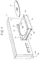
- the front panel of a player housing 1 has an inserting opening 1a in the form of a horizontally elongated rectangle through which a recording medium, namely, a disk 3 is inserted into the player housing 1 so as to be positioned at a disk playing position.
- the arrow X represents the left direction (as viewed from the player housing), the arrow Y the forward direction, and the arrow Z the upward direction.
- a movable disk bearing member namely, a tray 5 is provided in such a manner that it is movable forwardly and backwardly (in the direction of the arrow Y and in the opposite direction); that is, the tray 5 is reciprocated between a protruding position and an accommodating position by being pushed into and pulled out of the player housing 1 through the inserting opening 1a.
- the tray 5 has a decorating board 5a at the front end to completely close the inserting opening 1a.
- the front panel has a recess 1b around the opening 1a.
- the decorating board 5a is fitted in the recess 1b.
- the tray 5 is slidably mounted on a chassis 6 which is a base body in the player housing 1.
- the tray 5 is substantially in the form of a flat box and has two elongated extensions 5b and 5b on the right and left sides which are extended in the direction of the arrow Y.
- guide grooves 5c are formed in the lower surfaces of the extensions 5b, respectively, and slidably engaged with guide protrusions 6a, respectively, which are formed on the chassis 6.
- the tray 5 is shown in Figs. 5 through 8 in more detail.
- the extensions 5b and the guide grooves 5c are shown in Figs. 5, 6 and 8 in more detail.
- a circular recess 5d is formed in the upper surface of the front half of the tray 5.
- a turntable 10 and a table bearing 11 which are each in the form of a disk, and a locking ring, namely, a lock plate 12 are coaxially stacked (in the direction of the arrow Z) one on another.
- the turntable 10 is shown in Figs. 9 through 12 in detail, the table bearing 11 in Figs. 13 through 15, and the lock plate 12 in Figs. 16 through 20.
- the turntable 10 is formed by coaxially combining a disk bearing plate 14 adapted to bear a disk 3, and a boss 15 with a positioning protrusion 15a which is inserted into the central hole of a disk 3.
- the turntable 10 holds a disk 3 with the aid of a depressing or pressure member (described later), to turn or rotate it.
- Figs. 9 and 10 are a plan view and a vertical sectional view of the disk bearing plate 14, respectively.
- Figs. 11 and 12 are a front view (partly as a sectional view) and a bottom view of the boss 15, respectively.
- a thin-film-shaped table cloth 14a of rubber or the like is affixed to the disk bearing surface of the disk bearing plate 14.
- a spindle 17 is fixedly fitted in the boss 15 of the turntable 10, and it is rotatably supported on the table bearing 11. More specifically, as shown in Figs. 2, 4 and 13, a radial bearing 11a and a thrust bearing 11b are fitted in the table bearing 11, to support the spindle 17. An E ring 17a is mounted on the lower end portion of the spindle 17, so as to prevent the spindle 17 from coming off.
- the table bearing 11, which rotatably supports the turntable 10 is supported on the tray 5 through second vibration proofing means, namely, a coil spring 19.
- the coil spring 19 is positioned with its lower end portion fitted on a protrusion 5c' formed on the tray 5. That is, the turntable 10 is mounted on the tray 5 only by the single coil spring 19 which is an elastic member. Therefore, the turntable will flexibly follow the turning or rotating of the depressing member (described later). This will prevent the deflection of the rotation axis of the turntable which otherwise may be caused during rotation of the disk.
- the lock plate (or lock ring) 12 is provided below the turntable 10 and the table bearing 11 to lock the table bearing 11 and the turntable 10, which is rotatably supported by the table bering 11, to the tray 5 or to unlock them from the tray 5.
- the lock plate 12 is rotatably provided on the bottom of the circular recess 5d formed in the tray 5.
- the lock plate 12 is substantially in the form of a ring, and has three arcuate elongated holes 12a which are formed at equiangular intervals in its annular body.
- three T-shaped protrusions 5f are extended from the bottom of the aforementioned recess 5d.
- the T-shaped protrusions 5f are engaged with the elongated holes 12a, respectively; that is, the lock plate 12 is slidably engaged with the T-shaped protrusions 5f through the elongated holes 12a.
- the lock plate 12 has for instance five locking pieces 12c which are extended from the inner periphery of the annular body towards the center of rotation of the lock plate 12.
- Fig. 19 is an enlarged diagram showing one of the locking pieces 12c.
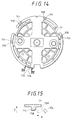
- Fig. 20 is a sectional view taken along line XX-XX in Fig. 19. As shown in Figs. 20 and 16, the upper surface of the end portion of each locking piece 12c includes a tapered surface 12d.
- Fig. 15 is a sectional view taken along line XV-XV in Fig. 14. As shown in Figs. 14 and 15, each protrusion 11c has a tapered surface at the end portion. As is apparent from Figs.
- both the tapered surfaces 12d of the locking protrusions 12c and the tapered surfaces 11d of the locked protrusion 11c are sloped downwardly (in the direction opposite to the direction of the arrow Z) as viewed in the direction of the arrow R.
- the table bearing 11 is supported through the coil spring 19 on the tray 5. Therefore, when the tapered surfaces 12d of the locking protrusion 12c engage with the tapered surfaces 11d of the locked protrusions 11c to push them, the table bearing 11 is slightly moved upwardly (in the direction of the arrow Z) by a wedge action. As shown in Figs. 2, 4, 5 and 7, three L-shaped receiving pieces 5h are formed at equiangular intervals on the tray 5. The L-shaped receiving pieces 5h receive the table bearing 11 with their upper portion abutted against the upper surface of the table bearing. That is, the table bearing 11 is locked from above and below by the receiving pieces 5h and the locking pieces 12c of the locking plate 12. In the case where the locking pieces 12c are not in engagement with the locked pieces 11c, the L-shaped receiving pieces 5h are spaced from the table bearing; that is, the receiving pieces 5h are not in contact with the table bearing.
- a coil spring 22 is connected to a protrusion 12f which is formed on the upper surface of the annular lock plate body of the lock plate 12.
- the coil spring 22 is also shown in Fig. 2.
- the other end of the coil spring 22 is connected to the tray 5, to urge the lock plate 12 counterclockwise (in the direction of the arrow R in Fig. 16); that is, the tapered surfaces 12d of the locking protrusions 12c are kept urged by the coil spring 22 to be engaged with the tapered surface 11d of the locked protrusions 11c of the table bearing 11.
- a pin 12g is embedded in the lower surface of the annular lock plate body of the lock plate 12 in such a manner that it is extended from a predetermined position on the lower surface.
- the pin 12g functions as follows: That is, when the tray 5 is pushed into the player housing 1, the pin 12g is engaged with a protrusion (not shown) extended from a predetermined position on the chassis 6, and the operation of pushing in the tray 5 causes the protrusion to react on the pin 12g, so that the pin 12g turns the lock plate 12 clockwise (in the direction opposite to the direction of the arrow R) in Fig. 16 against the elastic force of the coil spring 19.
- the locked pieces 11c of the table bearing 11 are disengaged from the locking pieces 12c of the lock plate 12; that is, the table bearing 11 and the turntable 10 are unlocked from the tray 5.
- the coil spring 19, the pin 12g of the lock plate 12, and the protrusion (not shown) formed on the chassis 6 so as to engage with pin 12g form locking annular body rotating means which turns the locking annular body, namely, the lock plate 12 in the forward direction and in the reverse direction as the tray 5 is pulled out of and pushed into the player housing 1.
- the locking annular body rotating means, the lock plate 12, the locked pieces 11d formed on the table bearing 11 so as to engage with the locking pieces 12d of the lock plate 12, and the receiving pieces 5h of the tray 5 form locking means for locking the turntable 10 to and unlocking it from the tray 5 as the tray 5 is pushed into and pulled out of the player housing 1.
- the turntable when the turntable is outside the player housing 1, it is fixedly locked to the tray 5 by the locking means. Hence, the turntable is not vibrated, thus providing a sufficiently high disk holding effect.
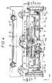
- a movable base 25 substantially in the form of a rectangular plate is provided above the chassis 6.
- a mechanical chassis 28 in the form of a flat plate is mounted on the movable base 25 through three first vibration proofing means, namely, floatable rubber members 27.
- a bearing board 30 is secured to the lower surface of the mechanical chassis 28 with a plurality of screws 31.
- a motor 33 is mounted on the bearing board 30 in such a manner that its output shaft is extended downwardly.
- a disk-shaped depressing member 34 is fixedly mounted on the output shaft of the motor 33, to abut against a disk 3 to be played and depress the disk 3 against the turntable 10.
- an optical pickup 36 is provided on the bearing board 30 in such a manner that it is movable along the recording surface of the disk 3.
- pickup driving means including an electric motor 37 is mounted on the bearing board 30, to move the optical pickup 36.
- the mechanical chassis 28, the bearing board 30, the motor 33, the depressing member 34, the optical pickup 36, and the pickup driving means including the motor 37 form playing means for playing the disk 3.
- Fig. 21 is an enlarged diagram of the chassis 6 shown in Fig. 2.
- the chassis 6, which is located below the movable base 25 supporting the above-described playing means has a bottom 6b, and a pair of vertical walls 6c and 6d rising from the right and left ends of the bottom 6b.
- Longitudinal movable cams 41 and 42 are coupled to the two vertical walls 6c and 6d, respectively, in such a manner that they are movable forwardly and backwardly (in the direction of the arrow Y and in the opposite direction).
- the movable cams 41 and 42 have two guide grooves 41a and two guide grooves 42a in the upper end portions, respectively.
- the guide grooves 41a and 42a are engaged with T-shaped protrusions 6f (as shown in Figs. 2, 4, 21 and 22) which are extended from the upper edges of the vertical walls 6c and 6d of the chassis 6, thus allowing the movable cams to freely move forwardly and backwardly.
- pins 25b are extended from the lower surface of the movable base 25; more specifically, two pins 25b are extended from each of the right and left ends of the lower surface of the movable base 25.
- These four pins 25b are slidably engaged with four guide grooves 6h, respectively, which are formed in the vertical walls 6c and 6d of the chassis 6 in such a manner that they are extended vertically. This engagement allows the chassis 6 to guide the movable base 25 vertically.
- the pins 25b of the movable base 25 are further slidably engaged with the cam holes 41b and 42b formed in the movable cams 41 and 42.
- the cam holes 41b formed in the movable cam 41 on the left side are inclined downwardly (in the direction opposite to the direction of the arrow Z) as viewed in the forward direction (in the direction of the arrow Y); whereas the cam holes 42b formed in the movable cam 42 on the right side are inclined upwardly (in the direction of the arrow Z) as viewed in the same direction.
- the movable cams 41 and 42 move relative to each other forwardly and backwardly, the movable base 25 is reciprocated vertically.
- a synchronizing lever 44 is provided between the right and left movable cams 42 and 41 and below the chassis 6.
- a pin 44a is embedded in the synchronizing lever 44 substantially at the center, and engaged with a round hole 6j formed in the bottom 6b of the chassis 6; that is, the synchronizing lever 44 is swingably mounted on the chassis 6 through the pin 44a.
- the synchronizing lever 44 is shown in Figs. 25 and 26 in more detail.
- two pawls 6k are extended downwardly from the bottom 6b of the chassis 6 in such a manner that they are positioned on both sides of the round hole 6j.
- the synchronizing lever 44 has two guide grooves 44c and 44d on both sides of the pin 44a.
- the guide grooves 44c and 44d are slidably engaged with the aforementioned pawls 6k, thereby to guide the turning of the synchronizing lever 44.
- elongated holes 44e and 44f are formed in two end portions of the synchronizing lever 44, respectively.
- the elongated holes 44e and 44f of the synchronizing lever 44 are engaged with pins 41d and 42d which are embedded in the lower end portions of the movable cams 41 and 42, respectively.
- the pins 41d and 42d of the movable cams 41 and 42 are inserted through elongated openings 6m (one of which is visible in Figs. 2 and 21) formed in the bottom of the chassis 6 and into the elongated holes 44e and 44f of the synchronizing lever 44.
- the right and left movable cams 42 and 41 being coupled through the synchronized lever 44 in the above-described manner, are reciprocated in synchronization with each other.
- an arcuate gear 44g is formed in a predetermined edge of a free end portion of the synchronizing lever 44, and a pin 44h is embedded in the upper surface of the synchronizing lever 44 at a predetermined position.
- the pin 44h is slidably engaged with a cam groove 5j formed in the lower surface of the tray 5 as shown in Fig. 8.
- the cam groove 5j is made up of a long straight portion 5k extended forwardly from the rear end of the tray 5, a short straight portion 5n extended forwardly toward the left from the front end of the long straight portion 5k, and a short straight portion 5m extended backwardly toward the left from the end of the short straight portion 5n.
- the tray 5 and the synchronizing lever 44 are provided on both sides of the bottom 6b of the chassis 6, respectively, the above-described pin 44h is inserted into the cam groove 5j through an arcuate opening 6n (shown in Fig. 21) formed in the bottom 6b of the chassis 6.
- the arcuate gear 44g of the synchronizing lever 44 is engageable with a compound gear 49 which is rotatably supported on a receiving plate 47 (shown in Figs. 2 and 22) which is coupled to the chassis 6 with screws or the like.
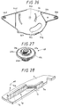
- the compound gear 49 as shown in Fig. 27, is made up of first through fourth circular gears 49a through 49d which are coaxially stacked one on another. The lowermost circular gear 49d is engaged with the arcuate gear 44g of the synchronizing lever 44.
- a large pulley 51 is rotatably mounted in front of the compound gear 49 on the lower surface of the chassis 6.
- an electric motor 52 is mounted on the rear end portion of the chassis 6 in such a manner that its output shaft is extended downwardly.
- An endless belt 53 is laid over a small pulley 52a mounted on the output shaft of the motor 52 and the above-described pulley 51.
- a circular gear 51a is formed on the upper surface of the pulley 51 in such a manner that the gear 51a and the pulley 51 form one unit.
- the circular gear 51a is engaged with the third circular gear 49c (counting from the top down) of the compound gear 49.
- the synchronizing lever 44 has an arcuate opening 44j, into which the circular gear 51a is inserted.
- the motor 52, the pulley 51 including the circular gear 51a, the small pulley 52a, and the endless belt 53 form torque applying means for applying torque to the compound gear 49.
- the compound gear 49 is made up of the four circular gears 49a through 49d.
- the top or first circular gear 49a and the second circular gear 49b are engaged with a rack 5p which, as shown in Figs. 4, 6, 7 and 8, is formed in the tray 5 in the direction of movement of the tray 5.
- Fig. 28 shows the rack as viewed with the rack's bottom up.
- the rack 5p of the tray 5 is made up of a long straight portion 5q which is extended forwardly from the rear end of the tray 5, a curved portion 5r extended from the end of the long straight portion 5q, and a short straight portion 5s extended from the end of the curved portion 5r in the same direction as the long straight portion 5q.
- the long straight portion 5q is engaged with the second, larger diameter circular gear 49b of the compound gear 49, and the short straight portion 55 is engaged with the top circular gear 49a which is smaller in diameter.
- the curved portion 5r between the straight portions 5q and 5s is engaged with an arcuate relay gear 49e which, as best shown in Fig. 27, is formed so as to couple the circular gears 49a and 49b to each other.
- the arrangement of the circular gears 49a and 49b, the arcuate relay gear 49e, and the rack 5p engaged therewith will be described in more detail later.
- the compound gear 49 the above-described torque applying means comprising the motor 52 to apply torque to the compound gear 49, the movable cams 41 and 42, the synchronizing lever 44, the guide grooves 6h formed in the chassis 6 to guide the movable base 25 vertically, and their relevant components, form displacing means for moving the playing means including the depressing member 34 towards and away from the turntable 10 on the tray 5.
- the three floatable rubber members 27 are arranged in a plane perpendicular to the axis of rotation of the motor 33; i.e., the axis of rotation of the depressing member 34 in such a manner that they are substantially at the same distance from the axis of rotation.
- the center of gravity G (shown in Fig. 3) of the above-described playing means is on the axis of rotation. This construction prevents the depressing member from being vibrated along the axis of rotation, and accordingly the disk from being vibrated in the plane perpendicular thereto. Thus, the disk is played smoothly.
- a circle 63 is drawn which internally touches the pitch circle 61 of the circular gear 49b of a large diameter and externally touches the pitch circle 62 of the circular gear 49a of a small diameter.
- the circle 63 thus drawn is employed as the pitch circle of the arcuate relay gear 49e.
- the pitch line of the curved portion 5r of the rack 5p which is to be engaged with the arcuate relay gear 49e is determined by construction as follows: First, as shown in Fig. 29, concentric circles are drawn which have a common center at the center of rotation of the circular gears 49a and 49b and pass through the pitch points of all the teeth of the arcuate relay gear 49e (the number of the circles thus drawn is equal to the number of teeth of the arcuate relay gear). Then, straight lines 65 through 73 are drawn which pass through the intersections of those circles and the axis A and are perpendicular to the axis A.
- a circle is drawn which has a radius r and its center at the pitch point of the common gear 75 of the arcuate relay gear 49e and the circular gear 49a, and the intersection of the straight line 66 and the circle thus drawn is obtained.
- Another circle having the same radius r is drawn with the intersection thus obtained as its center, and the intersection of the straight line 67 and the circle thus drawn is obtained.
- circles having the same radius r are drawn, and the intersections of the straight lines 68 through 73 and the circles thus drawn are obtained.
- the intersections thus obtained are connected with a smooth curve. This smooth curve is the pitch line 77 of the curved portion 5r of the rack 5p.
- Fig. 30 shows the engagement of the arcuate relay gear 49e and the curved portion 5r.
- the radius of the pitch circle of the arcuate relay gear 49e is R.
- the positional relationship between the center of the pitch circle of the arcuate relay gear 49e and the center of rotation O of the compound gear 49 is as shown in Fig. 30.
- a, b, c, d, e, ⁇ and ⁇ are defined as follows:
- a disk 3 to be played is placed on the turntable 10 on the tray 5.
- the turntable 10 is locked to the tray 5 because the lock plate 12 locks the table bearing 11 with the aid of the elastic force of the coil spring 22 as was described before.
- the turntable 10 will not be vibrated during the disk placing operation nor during a disk loading operation (described later).
- the operating section 87 on the front panel is operated to issue a loading start instruction to start a disk loading operation.
- the motor 52 is rotated in the forward direction, and accordingly, the compound gear 49 is rotated in the forward direction.
- the tray 5 having the rack 5p engaged with the compound gear 49 is moved backwardly (in the direction opposite to the direction of the arrow Y) into the player housing. That is, a tray accommodating operation is started.
- the second circular gear 49b (Fig. 27) is engaged with the long straight portion 5q of the rack 5p, and therefore the tray 5 is moved relatively quickly.
- the compound gear 49 engages with the rack 5p as follows: That is, the arcuate relay gear 49e continued to the circular gear 49b, and the small-diameter circular gear 49a are engaged with the curved portion 5r and the short straight portion 5s of the rack 5p successively. Thus, the speed of movement of the tray 5 is reduced gradually and smoothly.
- the tray accommodating operation reaches its final stage, the cam groove 5j formed in the lower surface of the tray 5 is in sliding contact with the pin 44h of the synchronizing lever 44 through its long straight portion 5k.
- the short straight portion 5n obliquely extended from the long straight portion 5k is brought into sliding contact with the pin 44h.
- the synchronizing lever 44 is turned counterclockwise through a small angle, so that the arcuate gear 44g of the synchronizing lever 44 is engaged with the lowermost circular gear 49d of the compound gear 49 (Fig. 27). Being triggered by this engagement, the compound gear 49 rotating for the final stage of the tray accommodating operation turns the synchronizing lever 44 clockwise through a large angle in Fig.
- the disk can be played.
- the lock plate 12 has been disengaged from the table bearing 11 against the elastic force of the coil spring 22, and the table bearing and the turntable 10 are in a floating state being supported only by the coil spring 19.
- the motor 33 When the disk is ready to be played as was described above, the motor 33 is rotated to turn the disk 3, while the motor 37 (shown in Fig. 3) is rotated to operate the optical pickup 36. Thus, the disk playing operation is carried out.
- the compound gear 49 is mounted on the chassis 6 which is on the stationary side, and the rack 5p engaged with the compound gear 49 is formed on the tray 5 which is on the movable side.
- the device may be so modified that the rack is on the stationary side, and the compound gear 49 is on the movable side.
- the driving means for moving the movable recording medium bearing member adapted to bear a recording medium and convey it between the disk playing position and the disk loading and unloading position comprises: the rack provided on one of the bearing member and the base body, which movably holds the bearing member, in such a manner that the rack is extended in a direction of movement of the bearing member; the gear unit provided on the other of the bearing member and the base body, and engaged with the rack; and the torque applying means for applying torque to the gear unit.
- the gear unit includes: a pair of circular gears which are different in diameter from each other and which are stacked coaxially as one unit; and the arcuate relay gear having the pitch circle which internally touches the pitch circle of one of the pair of circular gears which is larger in diameter and externally touches the other, and connects the pair of circular gears to each other.
- the rack has the straight portions engageable with the pair of circular gears, and the curved portion engageable with the arcuate relay gear.
- the rack engages with the large diameter circular gear, the arcuate relay gear, and the small diameter circular gear of the gear unit successively, so that the speed of movement of the movable bearing member is reduced continuously; that is, it is reduced smoothly.
- the predetermined detecting switch outputs the detection signal, and in response to the detection signal thus outputted, the application of torque to the gear unit is suspended instantaneously.
- the bearing member can be stopped in position with high accuracy.
- only one detecting switch is provided, and it is unnecessary to employ special components. Hence, the device can be manufactured at relatively low cost.
Abstract
Description
- The present invention relates to a recording medium conveying device which conveys a recording medium, such as an optical data recording disk (hereinafter referred to as "a disk", when applicable), to a playing position through an inserting opening formed in a player housing.
- An example of a conventional recording medium conveying device of this type is as shown in Figs. 35 through 37. As shown in Figs. 35 and 36, a movable
disk bearing member 253 adapted to bear adisk 252 is inserted into or protruded out of a player housing through aninserting opening 251a formed in thefront panel 251 of the player housing. Thedisk bearing member 253 comprises: acontainer supporting member 255 in the form of a flat box which is mounted on a chassis (not shown), which chassis is a base body or support fixedly provided in the player housing, in such a manner thatcontainer supporting member 255 is movable forwardly and backwardly (or in the direction of the arrow Y and in the opposite direction); and a flat-plate-shaped container 256 for bearing thedisk 252. Thecontainer 256 is coupled to thecontainer supporting member 255 in such a manner that thecontainer 256 is movable upwardly and downwardly (in the direction of the arrow Z and in the opposite direction). In addition, drive means (not shown) is provided which operates to move thecontainer supporting member 255 with respect to the aforementioned chassis, and to move thecontainer 256 with respect to thecontainer supporting member 255. - With the
disk bearing member 253 comprising thecontainer supporting member 255 and thecontainer 256 protruded from the player housing, adisk 252 is placed on the container. Under this condition, thecontainer supporting member 255 is pushed backwardly to position thedisk bearing member 253 inside the player housing. Thereafter, thecontainer 256 is moved downwardly toward thecontainer supporting member 255, thereby to set thedisk 252 at the disk playing position. The aforementioned drive means comprises: a drive source, namely, an electric motor (not shown); and power transmitting means (not shown) for converting the torque of the motor into the power of linear motion, and transmitting it to thecontainer supporting member 255 and thecontainer 256. - With such a recording medium conveying device, during the operation of pulling out the disk bearing member and/or during the operation of pushing in the disk bearing member, the speed of movement of the
disk bearing member 253 is reduced near the end of the operation to lessen the shock and noise so that the operation appears moderate. This will now be specifically described. Fig. 36 shows one example of a speed changing means for changing the speed of movement of thedisk bearing member 253. The speed changing means, as shown in Fig. 36, comprises front andrear detecting switches 258 and 259, respectively, which are arranged in a line (in the direction of the arrow Y) in the player housing so as to engage with the rear end of thecontainer supporting member 255 of thedisk bearing member 253. That is, when thedisk bearing member 253 is engaged with the front detecting switch 258 while being pushed into the housing, the voltage applied to the motor is decreased, and when it is engaged with therear detecting switch 259, the application of current to the motor is suspended. However, the above-described speed changing means is disadvantageous in the following points: The speed of movement of thedisk bearing member 253 is changed stepwise; that is, the operation of pushing in or pulling out the disk bearing member is not smooth. Since it is necessary to provide the twodetecting switches 258 and 259, the manufacturing cost is likewise increased. - Fig. 37 shows another example of the speed changing means which is well known in the art. The speed changing means includes only one
detecting switch 259 for stopping thedisk bearing member 253. In order to reduce the speed of movement of the disk bearing member, a rotary oil damper 260 is provided, and arack 255a is formed on the rear end portion of thecontainer supporting member 255 of thedisk bearing member 253 so as to engage with the gear of the oil damper 260. With such a speed changing means, during the operation of pushing in thedisk bearing member 253 therack 255a is engaged with the gear of the oil damper 26, thus reducing the speed of movement of thedisk bearing member 253. Thereafter, thedisk bearing member 253 engages with the detectingswitch 259, to suspend the application of current to the motor. However, the above speed changing means is also disadvantageous in that the speed of movement of the disk bearing member is not continuously changed, and since it is necessary to provide the oil damper 260 and therack 255a, the manufacturing cost is likewise increased. - Another example of the speed changing means may be considered which is designed as follows: In the speed changing means, unlike the above-described ones, the detecting switch 258 as shown in Fig. 36 and the oil damper 260 (and
rack 255a) as shown in Fig. 37 are not employed, and instead the detectingswitch 259 is positioned slightly before (in the direction of the arrow Y) that which is shown in Fig. 36 or 37. With such a speed changing means, upon engagement of thedisk bearing member 253 with the detecting switch, the application of current to the motor is suspended, and then thedisk bearing member 253 is allowed to run freely until it stops naturally. However, the speed changing means is still disadvantageous in that the speed of movement of the disk bearing member is not satisfactorily reduced, and it is rather difficult to accurately stop the disk bearing member in position. - In view of the foregoing, an object of the present invention is to provide a recording medium conveying device with which the speed of movement of the disk bearing member is reduced continuously and smoothly, and the disk bearing member can be stopped in place with high accuracy, and which is low in manufacturing cost.
- The foregoing object of the invention has been achieved by the provision of a recording medium conveying device for conveying a recording medium to a playing position through an inserting opening formed in a player housing, which, according to the invention, comprises: a base body provided in the player housing; a movable bearing member for bearing the recording medium, the movable bearing member being provided on the base body in such a manner that the movable bearing member is movable between a protruding position outside of the player housing and an accommodating position inside the player housing; and driving means for moving the bearing member. The driving means comprises: a rack provided on one of the base body and the bearing member, in such a manner that the rack is extended in a direction of movement of the bearing member; a gear unit provided on the other of the base body and the bearing member, and engaged with the rack; and torque applying means for applying torque to the gear unit. The gear unit includes a pair of circular gears different in diameter from each other which are stacked coaxially as one unit, and an arcuate relay gear having a pitch circle which internally touches the pitch circle of one of the pair of circular gears which is larger in diameter and externally touches the other, and connecting the pair of circular gears to each other. The rack has straight portions engageable with the pair of circular gears, and a curved portion engageable with the arcuate relay gear.
- In the recording medium conveying device thus designed, the rack engages with the large-diameter circular gear, the arcuate relay gear and the small-diameter circular gear of the gear unit successively, so that the speed of movement of the movable bearing member is reduced continuously and smoothly.
- In the accompanying drawings:-
- Fig. 1 is a perspective view showing the front panel of an automatic loading disk player which constitutes one embodiment of this invention;
- Fig. 2 is an exploded view showing the internal structure of the automatic loading disk player;
- Fig. 3 is a plan view showing the internal structure of the automatic loading disk player;
- Fig. 4 is a fragmentary view taken in the direction of the arrows substantially along line IV-IV in Fig. 3;
- Fig. 5 is a plan view of a tray in the internal structure shown in Fig. 2;
- Fig. 6 is a sectional view taken along line VI-VI in Fig. 5;
- Fig. 7 is a sectional view taken along line VII-VII in Fig. 5;
- Fig. 8 is a view taken in the direction of the arrows substantially along line VIII-VIII in Fig. 7;
- Fig. 9 is a plan view of a disk bearing plate forming a part of a turntable in the internal structure shown in Fig. 2;
- Fig. 10 is a vertical sectional view of the disk bearing plate shown in Fig. 9;
- Fig. 11 is a front view, partly as a sectional view, showing a boss forming a part of the turntable in the internal structure shown in Fig. 2;
- Fig. 12 is a bottom view of the boss shown in Fig. 11;
- Fig. 13 is a vertical sectional view of a table bearing in the internal structure shown in Fig. 2;
- Fig. 14 is a bottom view of the table bearing shown in Fig. 13;
- Fig. 15 is a sectional view taken along line XV-XV in Fig. 14;
- Fig. 16 is a plan view of a lock plate in the internal structure shown in Fig. 2;
- Fig. 17 is a front view of the lock plate shown in Fig. 16;
- Fig. 18 is a bottom view of the lock plate shown in Figs. 16 and 17;
- Fig. 19 is a plan view showing an engaging protrusion of the lock plate shown in Figs. 16 through 18;
- Fig. 20 is a sectional view taken along line XX-XX in Fig. 19;
- Fig. 21 is an exploded view showing a chassis, motor and detecting switch in the internal structure shown in Fig. 2;
- Fig. 22 is a view taken in the direction of the arrows substantially along line XXII-XXII in Fig. 4;
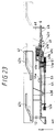
- Fig. 23 is a view taken in the direction of the arrows substantially along line XXIII-XXIII in Fig. 22;
- Fig. 24 is a perspective view of a pair of movable cams in the internal structure shown in Fig. 2;
- Fig. 25 is a vertical sectional view of a synchronizing lever in the internal structure shown in Fig. 2;
- Fig. 26 is a bottom view of the synchronizing lever shown in Fig. 25;
- Fig. 27 is a perspective view of a compound gear in the internal structure shown in Fig. 2;
- Fig. 28 is a perspective view of a rack formed in the tray shown in Figs. 5 through 8 in such a manner as to engage with the compound gear shown in Fig. 27;
- Fig. 29 is a diagram for a description of a construction which is made to obtain the pitch line of the arcuate relay gear of the compound gear shown in Fig. 27 and the curved portion of the rack shown in Fig. 28;
- Fig. 30 is a diagram for a description of a method of obtaining through calculation the pitch line of the curved portion of the rack shown in Fig. 28;
- Fig. 31 is a block diagram showing an operation control system for the automatic loading disk player shown in Figs. 1 through 30;
- Figs. 32, 33 and 34 are explanatory diagrams for a description of the operations of essential components in the automatic loading disk player shown in Figs. 1 through 30;
- Fig. 35 is a perspective view showing a disk player equipped with a conventional recording medium conveying device;
- Fig. 36 is a plan view outlining essential components in the internal structure of the disk player shown in Fig. 35; and
- Fig. 37 is a plan view outlining one modification of the internal structure of the disk player shown in Fig. 35.
- An automatic loading disk player will be described with reference to the accompanying drawings which is equipped with a recording medium conveying device which constitutes one embodiment of this invention.
- As shown in Fig. 1, the front panel of a
player housing 1 has an insertingopening 1a in the form of a horizontally elongated rectangle through which a recording medium, namely, adisk 3 is inserted into theplayer housing 1 so as to be positioned at a disk playing position. In Fig. 1, the arrow X represents the left direction (as viewed from the player housing), the arrow Y the forward direction, and the arrow Z the upward direction. - As also shown in Figs. 2 and 3, a movable disk bearing member, namely, a
tray 5 is provided in such a manner that it is movable forwardly and backwardly (in the direction of the arrow Y and in the opposite direction); that is, thetray 5 is reciprocated between a protruding position and an accommodating position by being pushed into and pulled out of theplayer housing 1 through the insertingopening 1a. Thetray 5 has adecorating board 5a at the front end to completely close the insertingopening 1a. As shown in Figs. 1 and 3, the front panel has arecess 1b around theopening 1a. Thedecorating board 5a is fitted in therecess 1b. Thetray 5 is slidably mounted on achassis 6 which is a base body in theplayer housing 1. Thetray 5 is substantially in the form of a flat box and has twoelongated extensions grooves 5c are formed in the lower surfaces of theextensions 5b, respectively, and slidably engaged withguide protrusions 6a, respectively, which are formed on thechassis 6. Thetray 5 is shown in Figs. 5 through 8 in more detail. Theextensions 5b and theguide grooves 5c are shown in Figs. 5, 6 and 8 in more detail. - As shown in Figs. 1 through 7, a
circular recess 5d is formed in the upper surface of the front half of thetray 5. In thecircular recess 5d, aturntable 10 and a table bearing 11 which are each in the form of a disk, and a locking ring, namely, alock plate 12 are coaxially stacked (in the direction of the arrow Z) one on another. Theturntable 10 is shown in Figs. 9 through 12 in detail, the table bearing 11 in Figs. 13 through 15, and thelock plate 12 in Figs. 16 through 20. - As is apparent from Fig. 4, the
turntable 10 is formed by coaxially combining adisk bearing plate 14 adapted to bear adisk 3, and aboss 15 with apositioning protrusion 15a which is inserted into the central hole of adisk 3. Theturntable 10 holds adisk 3 with the aid of a depressing or pressure member (described later), to turn or rotate it. Figs. 9 and 10 are a plan view and a vertical sectional view of thedisk bearing plate 14, respectively. Figs. 11 and 12 are a front view (partly as a sectional view) and a bottom view of theboss 15, respectively. As is seen from Figs. 4, 9 and 10, a thin-film-shapedtable cloth 14a of rubber or the like is affixed to the disk bearing surface of thedisk bearing plate 14. - As shown in Figs. 2 and 4, a
spindle 17 is fixedly fitted in theboss 15 of theturntable 10, and it is rotatably supported on thetable bearing 11. More specifically, as shown in Figs. 2, 4 and 13, aradial bearing 11a and athrust bearing 11b are fitted in the table bearing 11, to support thespindle 17. AnE ring 17a is mounted on the lower end portion of thespindle 17, so as to prevent thespindle 17 from coming off. - As shown in Figs. 2 and 4, the table bearing 11, which rotatably supports the
turntable 10, is supported on thetray 5 through second vibration proofing means, namely, acoil spring 19. Thecoil spring 19 is positioned with its lower end portion fitted on aprotrusion 5c' formed on thetray 5. That is, theturntable 10 is mounted on thetray 5 only by thesingle coil spring 19 which is an elastic member. Therefore, the turntable will flexibly follow the turning or rotating of the depressing member (described later). This will prevent the deflection of the rotation axis of the turntable which otherwise may be caused during rotation of the disk. - The lock plate (or lock ring) 12 is provided below the
turntable 10 and the table bearing 11 to lock the table bearing 11 and theturntable 10, which is rotatably supported by the table bering 11, to thetray 5 or to unlock them from thetray 5. Thelock plate 12 is rotatably provided on the bottom of thecircular recess 5d formed in thetray 5. As shown in Figs. 16 and 18, thelock plate 12 is substantially in the form of a ring, and has three arcuateelongated holes 12a which are formed at equiangular intervals in its annular body. As shown in Figs. 2, 5 and 6, three T-shapedprotrusions 5f are extended from the bottom of theaforementioned recess 5d. The T-shapedprotrusions 5f are engaged with theelongated holes 12a, respectively; that is, thelock plate 12 is slidably engaged with the T-shapedprotrusions 5f through theelongated holes 12a. As is apparent from Figs. 16 and 18, thelock plate 12 has for instance fivelocking pieces 12c which are extended from the inner periphery of the annular body towards the center of rotation of thelock plate 12. Fig. 19 is an enlarged diagram showing one of the lockingpieces 12c. Fig. 20 is a sectional view taken along line XX-XX in Fig. 19. As shown in Figs. 20 and 16, the upper surface of the end portion of each lockingpiece 12c includes a taperedsurface 12d. - As shown in Figs. 13 and 14, in correspondence to the above-described five
locking pieces 12c of thelock plate 12, locked or engagingprotrusions 11c are extended from the lower surface of the outer peripheral portion of the table bearing 11 which is to be locked by thelock plate 12. Fig. 15 is a sectional view taken along line XV-XV in Fig. 14. As shown in Figs. 14 and 15, eachprotrusion 11c has a tapered surface at the end portion. As is apparent from Figs. 15 and 16, by turning or rotating thelock plate 12 counterclockwise (in the direction of the arrow R) as viewed from above, thetapered surfaces 12d of the lockingprotrusions 12c are engaged with thetapered surfaces 11d of the lockedprotrusions 11 of the table bearing 11, respectively; whereas by turning or rotating it clockwise (in the direction opposite to the direction of the arrow R), thetapered surfaces 12d are disengaged from the taperedsurfaces 11d. As is seen from Fig. 15, both thetapered surfaces 12d of the lockingprotrusions 12c and thetapered surfaces 11d of the lockedprotrusion 11c are sloped downwardly (in the direction opposite to the direction of the arrow Z) as viewed in the direction of the arrow R. As was described above, the table bearing 11 is supported through thecoil spring 19 on thetray 5. Therefore, when thetapered surfaces 12d of the lockingprotrusion 12c engage with thetapered surfaces 11d of the lockedprotrusions 11c to push them, the table bearing 11 is slightly moved upwardly (in the direction of the arrow Z) by a wedge action. As shown in Figs. 2, 4, 5 and 7, three L-shapedreceiving pieces 5h are formed at equiangular intervals on thetray 5. The L-shapedreceiving pieces 5h receive the table bearing 11 with their upper portion abutted against the upper surface of the table bearing. That is, the table bearing 11 is locked from above and below by the receivingpieces 5h and the lockingpieces 12c of the lockingplate 12. In the case where the lockingpieces 12c are not in engagement with the lockedpieces 11c, the L-shapedreceiving pieces 5h are spaced from the table bearing; that is, the receivingpieces 5h are not in contact with the table bearing. - As shown in Figs. 16 and 17, one end of a
coil spring 22 is connected to a protrusion 12f which is formed on the upper surface of the annular lock plate body of thelock plate 12. Thecoil spring 22 is also shown in Fig. 2. The other end of thecoil spring 22 is connected to thetray 5, to urge thelock plate 12 counterclockwise (in the direction of the arrow R in Fig. 16); that is, thetapered surfaces 12d of the lockingprotrusions 12c are kept urged by thecoil spring 22 to be engaged with the taperedsurface 11d of the lockedprotrusions 11c of thetable bearing 11. - As shown in Figs. 4, 16, 17 and 18, a
pin 12g is embedded in the lower surface of the annular lock plate body of thelock plate 12 in such a manner that it is extended from a predetermined position on the lower surface. Thepin 12g functions as follows: That is, when thetray 5 is pushed into theplayer housing 1, thepin 12g is engaged with a protrusion (not shown) extended from a predetermined position on thechassis 6, and the operation of pushing in thetray 5 causes the protrusion to react on thepin 12g, so that thepin 12g turns thelock plate 12 clockwise (in the direction opposite to the direction of the arrow R) in Fig. 16 against the elastic force of thecoil spring 19. As a result, the lockedpieces 11c of the table bearing 11 are disengaged from the lockingpieces 12c of thelock plate 12; that is, the table bearing 11 and theturntable 10 are unlocked from thetray 5. - The
coil spring 19, thepin 12g of thelock plate 12, and the protrusion (not shown) formed on thechassis 6 so as to engage withpin 12g form locking annular body rotating means which turns the locking annular body, namely, thelock plate 12 in the forward direction and in the reverse direction as thetray 5 is pulled out of and pushed into theplayer housing 1. The locking annular body rotating means, thelock plate 12, the lockedpieces 11d formed on the table bearing 11 so as to engage with the lockingpieces 12d of thelock plate 12, and the receivingpieces 5h of thetray 5 form locking means for locking theturntable 10 to and unlocking it from thetray 5 as thetray 5 is pushed into and pulled out of theplayer housing 1. - As was described above, when the turntable is outside the
player housing 1, it is fixedly locked to thetray 5 by the locking means. Hence, the turntable is not vibrated, thus providing a sufficiently high disk holding effect. - As shown in Figs. 2, 3 and 4, a
movable base 25 substantially in the form of a rectangular plate is provided above thechassis 6. Amechanical chassis 28 in the form of a flat plate is mounted on themovable base 25 through three first vibration proofing means, namely,floatable rubber members 27. As shown in Figs. 2 and 4, a bearingboard 30 is secured to the lower surface of themechanical chassis 28 with a plurality of screws 31. Amotor 33 is mounted on the bearingboard 30 in such a manner that its output shaft is extended downwardly. A disk-shaped depressingmember 34 is fixedly mounted on the output shaft of themotor 33, to abut against adisk 3 to be played and depress thedisk 3 against theturntable 10. As shown in Figs. 2 and 3, anoptical pickup 36 is provided on the bearingboard 30 in such a manner that it is movable along the recording surface of thedisk 3. In addition, pickup driving means including anelectric motor 37 is mounted on the bearingboard 30, to move theoptical pickup 36. - The
mechanical chassis 28, the bearingboard 30, themotor 33, the depressingmember 34, theoptical pickup 36, and the pickup driving means including themotor 37 form playing means for playing thedisk 3. - Fig. 21 is an enlarged diagram of the
chassis 6 shown in Fig. 2. As is apparent from Figs. 2, 21, 4 and 22, thechassis 6, which is located below themovable base 25 supporting the above-described playing means, has a bottom 6b, and a pair ofvertical walls movable cams vertical walls movable cams guide grooves 41a and twoguide grooves 42a in the upper end portions, respectively. Theguide grooves protrusions 6f (as shown in Figs. 2, 4, 21 and 22) which are extended from the upper edges of thevertical walls chassis 6, thus allowing the movable cams to freely move forwardly and backwardly. - As shown in Figs. 2 and 4, four
pins 25b are extended from the lower surface of themovable base 25; more specifically, twopins 25b are extended from each of the right and left ends of the lower surface of themovable base 25. These fourpins 25b are slidably engaged with fourguide grooves 6h, respectively, which are formed in thevertical walls chassis 6 in such a manner that they are extended vertically. This engagement allows thechassis 6 to guide themovable base 25 vertically. - The
pins 25b of themovable base 25 are further slidably engaged with the cam holes 41b and 42b formed in themovable cams movable cam 41 on the left side are inclined downwardly (in the direction opposite to the direction of the arrow Z) as viewed in the forward direction (in the direction of the arrow Y); whereas the cam holes 42b formed in themovable cam 42 on the right side are inclined upwardly (in the direction of the arrow Z) as viewed in the same direction. Hence, as themovable cams movable base 25 is reciprocated vertically. - As shown in Figs. 2, 4 and 22, a synchronizing
lever 44 is provided between the right and leftmovable cams chassis 6. Apin 44a is embedded in the synchronizinglever 44 substantially at the center, and engaged with a round hole 6j formed in the bottom 6b of thechassis 6; that is, the synchronizinglever 44 is swingably mounted on thechassis 6 through thepin 44a. The synchronizinglever 44 is shown in Figs. 25 and 26 in more detail. As shown in Figs. 2, 4 and 21, twopawls 6k are extended downwardly from the bottom 6b of thechassis 6 in such a manner that they are positioned on both sides of the round hole 6j. On the other hand, the synchronizinglever 44 has two guide grooves 44c and 44d on both sides of thepin 44a. The guide grooves 44c and 44d are slidably engaged with theaforementioned pawls 6k, thereby to guide the turning of the synchronizinglever 44. As shown in Figs. 22, 25 and 26,elongated holes lever 44, respectively. Theelongated holes lever 44 are engaged withpins movable cams movable cams chassis 6, and the synchronizinglever 44 is on the other side, thepins movable cams elongated openings 6m (one of which is visible in Figs. 2 and 21) formed in the bottom of thechassis 6 and into theelongated holes lever 44. - The right and left
movable cams synchronized lever 44 in the above-described manner, are reciprocated in synchronization with each other. - As shown in Figs. 2 and 22, and Figs. 25 and 26, an
arcuate gear 44g is formed in a predetermined edge of a free end portion of the synchronizinglever 44, and apin 44h is embedded in the upper surface of the synchronizinglever 44 at a predetermined position. Thepin 44h is slidably engaged with acam groove 5j formed in the lower surface of thetray 5 as shown in Fig. 8. Thecam groove 5j is made up of a long straight portion 5k extended forwardly from the rear end of thetray 5, a short straight portion 5n extended forwardly toward the left from the front end of the long straight portion 5k, and a shortstraight portion 5m extended backwardly toward the left from the end of the short straight portion 5n. Since thetray 5 and the synchronizinglever 44 are provided on both sides of the bottom 6b of thechassis 6, respectively, the above-describedpin 44h is inserted into thecam groove 5j through anarcuate opening 6n (shown in Fig. 21) formed in the bottom 6b of thechassis 6. - The
arcuate gear 44g of the synchronizinglever 44 is engageable with acompound gear 49 which is rotatably supported on a receiving plate 47 (shown in Figs. 2 and 22) which is coupled to thechassis 6 with screws or the like. Thecompound gear 49, as shown in Fig. 27, is made up of first through fourthcircular gears 49a through 49d which are coaxially stacked one on another. The lowermostcircular gear 49d is engaged with thearcuate gear 44g of the synchronizinglever 44. - As shown in Figs. 2, 22 and 23, a
large pulley 51 is rotatably mounted in front of thecompound gear 49 on the lower surface of thechassis 6. As shown in Figs. 3 and 21, anelectric motor 52 is mounted on the rear end portion of thechassis 6 in such a manner that its output shaft is extended downwardly. Anendless belt 53 is laid over asmall pulley 52a mounted on the output shaft of themotor 52 and the above-describedpulley 51. Acircular gear 51a is formed on the upper surface of thepulley 51 in such a manner that thegear 51a and thepulley 51 form one unit. Thecircular gear 51a is engaged with the thirdcircular gear 49c (counting from the top down) of thecompound gear 49. As shown in Figs. 2, 22 and 26, the synchronizinglever 44 has anarcuate opening 44j, into which thecircular gear 51a is inserted. - The
motor 52, thepulley 51 including thecircular gear 51a, thesmall pulley 52a, and theendless belt 53 form torque applying means for applying torque to thecompound gear 49. - As was described above, the
compound gear 49 is made up of the fourcircular gears 49a through 49d. The top or firstcircular gear 49a and the secondcircular gear 49b are engaged with arack 5p which, as shown in Figs. 4, 6, 7 and 8, is formed in thetray 5 in the direction of movement of thetray 5. Fig. 28 shows the rack as viewed with the rack's bottom up. As shown in Figs. 28 and 8, therack 5p of thetray 5 is made up of a long straight portion 5q which is extended forwardly from the rear end of thetray 5, acurved portion 5r extended from the end of the long straight portion 5q, and a shortstraight portion 5s extended from the end of thecurved portion 5r in the same direction as the long straight portion 5q. The long straight portion 5q is engaged with the second, larger diametercircular gear 49b of thecompound gear 49, and the shortstraight portion 55 is engaged with the topcircular gear 49a which is smaller in diameter. Thecurved portion 5r between thestraight portions 5q and 5s is engaged with anarcuate relay gear 49e which, as best shown in Fig. 27, is formed so as to couple thecircular gears circular gears arcuate relay gear 49e, and therack 5p engaged therewith will be described in more detail later. - The
compound gear 49, therack 5p formed in thetray 5 for engaging with thecompound gear 49, and the above-described torque applying means comprising themotor 52 to apply torque to thecompound gear 49, form driving means for moving the tray back and forth. The driving means, and thechassis 6 which is a base body for guiding thetray 5, form a recording medium conveying device for conveying a recording medium, namely, adisk 3 to a playing position. - The
compound gear 49, the above-described torque applying means comprising themotor 52 to apply torque to thecompound gear 49, themovable cams lever 44, theguide grooves 6h formed in thechassis 6 to guide themovable base 25 vertically, and their relevant components, form displacing means for moving the playing means including thedepressing member 34 towards and away from theturntable 10 on thetray 5. - The installation of the above-described playing means and the above-described first vibration proofing means comprising three
floatable rubber members 27 to support the playing means above the chassis in a floating mode will now be described. - As shown in Figs. 2 and 3, the three
floatable rubber members 27 are arranged in a plane perpendicular to the axis of rotation of themotor 33; i.e., the axis of rotation of thedepressing member 34 in such a manner that they are substantially at the same distance from the axis of rotation. The center of gravity G (shown in Fig. 3) of the above-described playing means is on the axis of rotation. This construction prevents the depressing member from being vibrated along the axis of rotation, and accordingly the disk from being vibrated in the plane perpendicular thereto. Thus, the disk is played smoothly. - Now, the arrangement of the two
circular gears compound gear 49, thearcuate relay gear 49e provided to couple thecircular gears rack 5p of thetray 5 engaged with them will be described in more detail. - As shown in Fig. 29, as for the
arcuate relay gear 49e of thecompound gear 49, acircle 63 is drawn which internally touches thepitch circle 61 of thecircular gear 49b of a large diameter and externally touches thepitch circle 62 of thecircular gear 49a of a small diameter. Thecircle 63 thus drawn is employed as the pitch circle of thearcuate relay gear 49e. - On the other hand, the pitch line of the
curved portion 5r of therack 5p which is to be engaged with thearcuate relay gear 49e is determined by construction as follows:
First, as shown in Fig. 29, concentric circles are drawn which have a common center at the center of rotation of thecircular gears arcuate relay gear 49e (the number of the circles thus drawn is equal to the number of teeth of the arcuate relay gear). Then,straight lines 65 through 73 are drawn which pass through the intersections of those circles and the axis A and are perpendicular to the axis A. Next, a circle is drawn which has a radius r and its center at the pitch point of thecommon gear 75 of thearcuate relay gear 49e and thecircular gear 49a, and the intersection of thestraight line 66 and the circle thus drawn is obtained. Another circle having the same radius r is drawn with the intersection thus obtained as its center, and the intersection of thestraight line 67 and the circle thus drawn is obtained. Similarly, with respect to the remainingstraight lines 68 through 73, circles having the same radius r are drawn, and the intersections of thestraight lines 68 through 73 and the circles thus drawn are obtained. The intersections thus obtained are connected with a smooth curve. This smooth curve is thepitch line 77 of thecurved portion 5r of therack 5p. - The pitch line of the
curved portion 5r of therack 5p has been obtained by construction; however, it may be obtained by calculation as follows:
Fig. 30 shows the engagement of thearcuate relay gear 49e and thecurved portion 5r. As shown in Fig. 30, the radius of the pitch circle of thearcuate relay gear 49e is R. The positional relationship between the center of the pitch circle of thearcuate relay gear 49e and the center of rotation O of thecompound gear 49 is as shown in Fig. 30. In Fig. 30, a, b, c, d, e, α and ϑ are defined as follows: - a:
- the locus of the center of rotation of the
compound gear 49; - b:
- the straight line which passes through the center of the
arcuate relay gear 49e and is perpendicular to the line a; - c:
- the center of the
arcuate relay gear 49e; - d:
- the contact point of the
pitch circle 63 of thearcuate relay gear 49e and thecurved portion 5r; - e:
- the distance between the center c and the center O of the
compound gear 49; - ϑ:
- the angel between the straight line b and the line connecting the center O and the center c; and
- α:
- the angle between the straight line b and the line connecting the point d and the center c.
- Now, the operation of the auto-loading disk player thus constructed will be described with reference to Figs. 32 through 34. It is assumed that the
tray 5 has been pulled out of theplayer housing 1 as shown in Figs. 1 and 3. - After the
tray 5 has been pulled out of theplayer housing 1 as shown in Fig. 1, adisk 3 to be played is placed on theturntable 10 on thetray 5. In this case, theturntable 10 is locked to thetray 5 because thelock plate 12 locks the table bearing 11 with the aid of the elastic force of thecoil spring 22 as was described before. Hence, theturntable 10 will not be vibrated during the disk placing operation nor during a disk loading operation (described later). - After the
disk 3 is placed on theturntable 10, the operatingsection 87 on the front panel is operated to issue a loading start instruction to start a disk loading operation. - In response to the loading start instruction, first the
motor 52 is rotated in the forward direction, and accordingly, thecompound gear 49 is rotated in the forward direction. As a result, thetray 5 having therack 5p engaged with thecompound gear 49 is moved backwardly (in the direction opposite to the direction of the arrow Y) into the player housing. That is, a tray accommodating operation is started. As shown in Fig. 32, for the period of time between a certain time instant in the tray accommodating operation and near the end of the same, the secondcircular gear 49b (Fig. 27) is engaged with the long straight portion 5q of therack 5p, and therefore thetray 5 is moved relatively quickly. As the tray accommodating operation comes near the end, thecompound gear 49 engages with therack 5p as follows: That is, thearcuate relay gear 49e continued to thecircular gear 49b, and the small-diameter circular gear 49a are engaged with thecurved portion 5r and the shortstraight portion 5s of therack 5p successively. Thus, the speed of movement of thetray 5 is reduced gradually and smoothly. - On the other hand, until the tray accommodating operation reaches its final stage, the
cam groove 5j formed in the lower surface of thetray 5 is in sliding contact with thepin 44h of the synchronizinglever 44 through its long straight portion 5k. In the final stage of the tray accommodating operation, the short straight portion 5n obliquely extended from the long straight portion 5k is brought into sliding contact with thepin 44h. As a result, the synchronizinglever 44 is turned counterclockwise through a small angle, so that thearcuate gear 44g of the synchronizinglever 44 is engaged with the lowermostcircular gear 49d of the compound gear 49 (Fig. 27). Being triggered by this engagement, thecompound gear 49 rotating for the final stage of the tray accommodating operation turns the synchronizinglever 44 clockwise through a large angle in Fig. 22; that is, the synchronizinglever 44 is turned from the position indicated by the solid lines to the position indicated by the two-dot chain lines. Hence, as is seen from Fig. 22, the right and leftmovable cams lever 44 are moved backwardly and forwardly, respectively. This relative movement of the twomovable cams movable base 25 which is in sliding contact with the cam holes 41b and 42b of the movable cams through thepins 25b. - The operation of accommodating the tray, and operation of lowering the
movable base 25 are carried out as described above. When these operations come to an end, as shown in Fig. 22, the synchronizinglever 44 engages with the swinging portion of theintermediate lever 82, to swing it counterclockwise in Fig. 22. As a result, theprotrusion 82b of theintermediate lever 82 engages with theoperating piece 81a of the detectingswitch 81, to activate theswitch 81. As a result, the detectingswitch 81 outputs the detection signal, which is applied to the CPU 85 (Fig. 31). In response to the detection signal, theCPU 85 operates to stop themotor 52. Thus, thedisk 3 has been clamped by theturntable 10 and thedepressing member 34. - When the synchronizing
lever 44 swings as was described above, thepin 44h of the synchronizing lever is moved from the straight portion 5n of thecam groove 5j of thetray 5 to theportion 5m, so that thetray 5 is locked with respect to theplayer housing 1. - Thus, the disk can be played. In this state, the
lock plate 12 has been disengaged from the table bearing 11 against the elastic force of thecoil spring 22, and the table bearing and theturntable 10 are in a floating state being supported only by thecoil spring 19. In the floating state, the clamp force W applied to thedisk 3 is as follows:

where - WM:
- the weight of the mechanism (the playing means comprising the
mechanical chassis 28, the bearingboard 30, themotor 33 mounted on the bearing board, and the depressing member 34) supported by the floatable rubber members 27 (shown in Fig. 2 for instance); - ω₁:
- the holding force of the three
floatable rubber members 27; - ω₂:
- the holding force of the
coil spring 19; - WD:
- the weight of the
disk 3; - WT:
- the weight of the
turntable 10 and thetable bearing 11. - When the disk is ready to be played as was described above, the
motor 33 is rotated to turn thedisk 3, while the motor 37 (shown in Fig. 3) is rotated to operate theoptical pickup 36. Thus, the disk playing operation is carried out. - After the disk playing operation is ended, the
disk 3 is moved out of theplayer housing 1. The detailed description of this disk returning operation will be omitted, because it is achieved by performing the above-described operations in the reverse order. - In the above-described embodiment, the
compound gear 49 is mounted on thechassis 6 which is on the stationary side, and therack 5p engaged with thecompound gear 49 is formed on thetray 5 which is on the movable side. However, the device may be so modified that the rack is on the stationary side, and thecompound gear 49 is on the movable side. - In the recording medium conveying device of the invention, the driving means for moving the movable recording medium bearing member adapted to bear a recording medium and convey it between the disk playing position and the disk loading and unloading position, comprises: the rack provided on one of the bearing member and the base body, which movably holds the bearing member, in such a manner that the rack is extended in a direction of movement of the bearing member; the gear unit provided on the other of the bearing member and the base body, and engaged with the rack; and the torque applying means for applying torque to the gear unit. The gear unit includes: a pair of circular gears which are different in diameter from each other and which are stacked coaxially as one unit; and the arcuate relay gear having the pitch circle which internally touches the pitch circle of one of the pair of circular gears which is larger in diameter and externally touches the other, and connects the pair of circular gears to each other. The rack has the straight portions engageable with the pair of circular gears, and the curved portion engageable with the arcuate relay gear.
- In the recording medium conveying device according to the invention, the rack engages with the large diameter circular gear, the arcuate relay gear, and the small diameter circular gear of the gear unit successively, so that the speed of movement of the movable bearing member is reduced continuously; that is, it is reduced smoothly. In addition, when the bearing member has been accommodated in the player housing, the predetermined detecting switch outputs the detection signal, and in response to the detection signal thus outputted, the application of torque to the gear unit is suspended instantaneously. Thus, the bearing member can be stopped in position with high accuracy. In the recording medium conveying device, only one detecting switch is provided, and it is unnecessary to employ special components. Hence, the device can be manufactured at relatively low cost.
e sinϑ = R sinα
or
α = sin⁻¹(e sinϑ/R)
y = R cosα- e cosϑ
As shown in Figs. 2, 21 and 22, a detecting
Claims (4)
- A recording medium conveying device for conveying a recording medium to a playing position through an inserting opening formed in a player housing, the recording medium conveying device comprising:
a base body provided in said player housing;
a movable recording medium bearing member for bearing said recording medium, said movable recording medium bearing member being provided on said base body so that said movable recording medium bearing member is movable between a protruding position outside said player housing and an accommodating position inside said player housing;
driving means for moving said movable recording medium bearing member,
said driving means comprising:
a rack provided on one of said base body and said movable recording medium bearing member, so that said rack is extended in a direction of movement of said movable recording medium bearing member;
a gear unit provided on the other of said base body and said movable recording medium bearing member, and engaged with said rack; and
torque applying means for applying torque to said gear unit,
said gear unit including a pair of circular gears different in diameter from each other and which are stacked coaxially as a single unit; and
an arcuate relay gear having a pitch circle which internally touches a pitch circle of one of said pair of circular gears having a larger diameter and externally touches the other of said pair of circular gears, and connecting said pair of circular gears to each other,
said rack having straight portions engageable with said pair of circular gears, and a curved portion engageable with said arcuate relay gear. - The recording medium conveying device according to claim 1, wherein said recording medium comprises an optical data recording disk.
- The recording medium conveying device according to claim 2, wherein said movable recording medium bearing member comprises a tray having a circular recess for accommodating a corresponding said optical data recording disk.
- The recording medium conveying device according to claim 1, wherein said torque applying means comprises:
a motor having an output shaft and being mounted to said base body;
a small pulley mounted on the output shaft of said motor;
a large pulley rotatably mounted on said base body proximate to said gear unit;
a circular gear formed on an upper surface of said large pulley and being engaged with said gear unit; and
an endless belt laid over said small pulley and said large pulley.
Applications Claiming Priority (2)
| Application Number | Priority Date | Filing Date | Title |
|---|---|---|---|
| JP3120479A JP2842952B2 (en) | 1991-05-24 | 1991-05-24 | Recording medium transport device |
| JP120479/91 | 1991-05-24 |
Publications (3)
| Publication Number | Publication Date |
|---|---|
| EP0521217A2 true EP0521217A2 (en) | 1993-01-07 |
| EP0521217A3 EP0521217A3 (en) | 1993-06-16 |
| EP0521217B1 EP0521217B1 (en) | 1997-03-19 |
Family
ID=14787196
Family Applications (1)
| Application Number | Title | Priority Date | Filing Date |
|---|---|---|---|
| EP91311611A Expired - Lifetime EP0521217B1 (en) | 1991-05-24 | 1991-12-13 | Recording medium conveying device |
Country Status (4)
| Country | Link |
|---|---|
| US (1) | US5195078A (en) |
| EP (1) | EP0521217B1 (en) |
| JP (1) | JP2842952B2 (en) |
| DE (1) | DE69125274T2 (en) |
Cited By (6)
| Publication number | Priority date | Publication date | Assignee | Title |
|---|---|---|---|---|
| US5544147A (en) * | 1994-08-17 | 1996-08-06 | Sharp Kabushiki Kaisha | Disk reproducing apparatus |
| US5724331A (en) * | 1994-08-25 | 1998-03-03 | Discovision Associates | Disk drive system having improved cartridge-loading apparatus including direct drive gear train and methods for making and operating same |
| EP0829871A1 (en) * | 1996-09-12 | 1998-03-18 | Lg Electronics Inc. | Disk tray shifting device for optical disk player |
| US6009061A (en) * | 1994-08-25 | 1999-12-28 | Discovision Associates | Cartridge-loading apparatus with improved base plate and cartridge receiver latch |
| GB2378807A (en) * | 2001-06-12 | 2003-02-19 | Inc Technologies | Drawer support mechanism for electrical device. |
| EP1675115A2 (en) * | 2004-12-24 | 2006-06-28 | ORION ELECTRIC CO., Ltd. | Electronic apparatus including recording and reproducing device |
Families Citing this family (16)
| Publication number | Priority date | Publication date | Assignee | Title |
|---|---|---|---|---|
| KR940011086B1 (en) * | 1991-12-23 | 1994-11-23 | 삼성전자 주식회사 | Laser disk player |
| JP2815525B2 (en) | 1992-08-19 | 1998-10-27 | 三菱電機株式会社 | Auto changer device |
| US5907529A (en) * | 1993-08-06 | 1999-05-25 | Sony Corporation, Japan | Translation and rotation mechanism for cartridge loading |
| JPH07141743A (en) * | 1993-11-12 | 1995-06-02 | Nakamichi Corp | Tray driving device for disk player |
| JPH07220359A (en) * | 1994-01-31 | 1995-08-18 | Sony Corp | Disk player device |
| US6034927A (en) * | 1994-10-20 | 2000-03-07 | Sony Corporation | Carriage for optical disk storage and retrieval array |
| US6016236A (en) * | 1996-10-21 | 2000-01-18 | Onstream, Inc. | Apparatus for the storage and/or reproduction of information on/from an information carrier |
| FR2764432B1 (en) * | 1997-06-05 | 1999-08-06 | Seb Sa | CONTROL DEVICE FOR THERMOSTAT |
| JP3818756B2 (en) * | 1997-10-31 | 2006-09-06 | 富士通株式会社 | Storage device |
| US6490238B1 (en) * | 2000-01-28 | 2002-12-03 | Hewlett-Packard Company | CD transport tray drive having elastomeric drive wheel surface |
| DE10043298A1 (en) * | 2000-09-02 | 2002-03-14 | Philips Corp Intellectual Pty | Device for playing storage disks |
| JP2005069262A (en) * | 2003-08-27 | 2005-03-17 | Orion Denki Kk | Electronics device |
| JP2006155731A (en) * | 2004-11-29 | 2006-06-15 | Orion Denki Kk | Disk device comprising lateral tray vibration preventing mechanism |
| US7988255B2 (en) * | 2008-01-04 | 2011-08-02 | Eastman Kodak Company | Full function maintenance station |
| JP5051276B2 (en) * | 2010-06-10 | 2012-10-17 | カシオ計算機株式会社 | Nail printing apparatus and printing control method |
| TWI595481B (en) * | 2015-12-29 | 2017-08-11 | 光寶電子(廣州)有限公司 | Disc drive |
Citations (9)
| Publication number | Priority date | Publication date | Assignee | Title |
|---|---|---|---|---|
| EP0070062A1 (en) * | 1981-07-04 | 1983-01-19 | Philips Patentverwaltung GmbH | Device for the automatic loading and ejecting of an information carrier |
| JPS60138765A (en) * | 1983-12-27 | 1985-07-23 | Kohei Muramoto | Cassette loading device |
| JPS6266458A (en) * | 1985-09-19 | 1987-03-25 | Toshiba Corp | Loading device |
| JPS62214545A (en) * | 1986-03-14 | 1987-09-21 | Mitsubishi Electric Corp | Cassette loading device |
| JPS63249958A (en) * | 1987-04-06 | 1988-10-17 | Sony Corp | Cassette mounting device |
| EP0288875A2 (en) * | 1987-04-28 | 1988-11-02 | Pioneer Electronic Corporation | Disk Loader |
| EP0332171A2 (en) * | 1988-03-08 | 1989-09-13 | Sanyo Electric Co., Ltd. | Disc player |
| EP0356984A2 (en) * | 1988-08-30 | 1990-03-07 | Sanyo Electric Co., Ltd. | Disc player |
| JPH02177160A (en) * | 1988-12-28 | 1990-07-10 | Mitsubishi Electric Corp | Cassette loader |
Family Cites Families (2)
| Publication number | Priority date | Publication date | Assignee | Title |
|---|---|---|---|---|
| JPS60150262A (en) * | 1984-01-13 | 1985-08-07 | Sony Corp | Disk player |
| US5123005A (en) * | 1989-12-28 | 1992-06-16 | Sony Corporation | Disc tray loading mechanism for reducing loading and unloading mechanical shocks |
-
1991
- 1991-05-24 JP JP3120479A patent/JP2842952B2/en not_active Expired - Fee Related
- 1991-12-11 US US07/808,791 patent/US5195078A/en not_active Expired - Lifetime
- 1991-12-13 DE DE69125274T patent/DE69125274T2/en not_active Expired - Fee Related
- 1991-12-13 EP EP91311611A patent/EP0521217B1/en not_active Expired - Lifetime
Patent Citations (9)
| Publication number | Priority date | Publication date | Assignee | Title |
|---|---|---|---|---|
| EP0070062A1 (en) * | 1981-07-04 | 1983-01-19 | Philips Patentverwaltung GmbH | Device for the automatic loading and ejecting of an information carrier |
| JPS60138765A (en) * | 1983-12-27 | 1985-07-23 | Kohei Muramoto | Cassette loading device |
| JPS6266458A (en) * | 1985-09-19 | 1987-03-25 | Toshiba Corp | Loading device |
| JPS62214545A (en) * | 1986-03-14 | 1987-09-21 | Mitsubishi Electric Corp | Cassette loading device |
| JPS63249958A (en) * | 1987-04-06 | 1988-10-17 | Sony Corp | Cassette mounting device |
| EP0288875A2 (en) * | 1987-04-28 | 1988-11-02 | Pioneer Electronic Corporation | Disk Loader |
| EP0332171A2 (en) * | 1988-03-08 | 1989-09-13 | Sanyo Electric Co., Ltd. | Disc player |
| EP0356984A2 (en) * | 1988-08-30 | 1990-03-07 | Sanyo Electric Co., Ltd. | Disc player |
| JPH02177160A (en) * | 1988-12-28 | 1990-07-10 | Mitsubishi Electric Corp | Cassette loader |
Non-Patent Citations (5)
| Title |
|---|
| PATENT ABSTRACTS OF JAPAN vol. 009, no. 308 (P-410)4 December 1985 & JP-A-60 138 765 ( KOUHEI MARUMOTO ) 23 July 1985 * |
| PATENT ABSTRACTS OF JAPAN vol. 011, no. 261 (P-609)25 August 1987 & JP-A-62 066 458 ( TOSHIBA ) 25 March 1987 * |
| PATENT ABSTRACTS OF JAPAN vol. 012, no. 076 (P-675)10 March 1988 & JP-A-62 214 545 ( MITSUBISHI ) 21 September 1987 * |
| PATENT ABSTRACTS OF JAPAN vol. 013, no. 059 (P-826)10 February 1989 & JP-A-63 249 958 ( SONY ) 17 October 1988 * |
| PATENT ABSTRACTS OF JAPAN vol. 014, no. 449 (P-1111)26 September 1990 & JP-A-02 177 160 ( MITSUBISHI ) 10 July 1990 * |
Cited By (14)
| Publication number | Priority date | Publication date | Assignee | Title |
|---|---|---|---|---|
| CN1076846C (en) * | 1994-08-17 | 2001-12-26 | 夏普公司 | Disk reproducing apparatus |
| US5544147A (en) * | 1994-08-17 | 1996-08-06 | Sharp Kabushiki Kaisha | Disk reproducing apparatus |
| US6411584B2 (en) | 1994-08-25 | 2002-06-25 | Discovision Associates | Cartridge loading apparatus and methods of manufacturing and operating same |
| US6009061A (en) * | 1994-08-25 | 1999-12-28 | Discovision Associates | Cartridge-loading apparatus with improved base plate and cartridge receiver latch |
| US6201659B1 (en) | 1994-08-25 | 2001-03-13 | Discovision Associates | Cartridge-loading apparatus with tilting bias coil assembly |
| US5724331A (en) * | 1994-08-25 | 1998-03-03 | Discovision Associates | Disk drive system having improved cartridge-loading apparatus including direct drive gear train and methods for making and operating same |
| EP0829871A1 (en) * | 1996-09-12 | 1998-03-18 | Lg Electronics Inc. | Disk tray shifting device for optical disk player |
| US6449233B1 (en) | 1996-09-12 | 2002-09-10 | Lg Electronics Inc. | Disk tray shifting device for an optical disk player |
| US6459671B1 (en) | 1996-09-12 | 2002-10-01 | Lg Electronics Inc. | Disk tray shifting device for an optical disk player |
| US6498774B2 (en) | 1996-09-12 | 2002-12-24 | Lg Electronics Inc. | Disk tray locking device for an optical system |
| GB2378807A (en) * | 2001-06-12 | 2003-02-19 | Inc Technologies | Drawer support mechanism for electrical device. |
| GB2378807B (en) * | 2001-06-12 | 2005-06-22 | Inc Technologies | Drawer support mechanism |
| EP1675115A2 (en) * | 2004-12-24 | 2006-06-28 | ORION ELECTRIC CO., Ltd. | Electronic apparatus including recording and reproducing device |
| EP1675115A3 (en) * | 2004-12-24 | 2007-09-05 | ORION ELECTRIC CO., Ltd. | Electronic apparatus including recording and reproducing device |
Also Published As
| Publication number | Publication date |
|---|---|
| US5195078A (en) | 1993-03-16 |
| EP0521217A3 (en) | 1993-06-16 |
| JP2842952B2 (en) | 1999-01-06 |
| DE69125274D1 (en) | 1997-04-24 |
| DE69125274T2 (en) | 1997-09-18 |
| EP0521217B1 (en) | 1997-03-19 |
| JPH04345955A (en) | 1992-12-01 |
Similar Documents
| Publication | Publication Date | Title |
|---|---|---|
| EP0521217B1 (en) | Recording medium conveying device | |
| EP0424983A1 (en) | Multi-disk player system | |
| GB2172423A (en) | Power-operated device for assisting loading and unloading a disc player | |
| US5128918A (en) | Disk loading device for disk player | |
| US4796251A (en) | Dual-sized disk player | |
| EP0514607A1 (en) | Auto-loading disk player | |
| US7475409B2 (en) | Disc changer device | |
| EP0822549B1 (en) | Disk player | |
| EP0514606A1 (en) | Disk player having playing device supported by a player housing through vibration absorbing members | |
| KR920002608B1 (en) | Audio reproduction device with head base moving mechanism | |
| JPH064446Y2 (en) | Disk player | |
| JP2953845B2 (en) | Disk unit | |
| JP2953846B2 (en) | Disk unit | |
| JP2525350B2 (en) | Recording or playback device | |
| JPS61229288A (en) | Disk player | |
| JPH047026B2 (en) | ||
| JPS6139273A (en) | Head position initial set system of disc device | |
| JPS61236061A (en) | Disk player | |
| JP2568811Y2 (en) | Disk unit | |
| JPS61236086A (en) | Disc player | |
| JPH06231529A (en) | Detecting apparatus for rotating position | |
| JPH0339347B2 (en) | ||
| JPH09180333A (en) | Recording medium carrier | |
| WO2006132299A1 (en) | Drive changeover device, drive device, and disk device | |
| JPS59135667A (en) | Optical disk record reproducing device |
Legal Events
| Date | Code | Title | Description |
|---|---|---|---|
| PUAI | Public reference made under article 153(3) epc to a published international application that has entered the european phase |
Free format text: ORIGINAL CODE: 0009012 |
|
| AK | Designated contracting states |
Kind code of ref document: A2 Designated state(s): DE FR GB |
|
| PUAL | Search report despatched |
Free format text: ORIGINAL CODE: 0009013 |
|
| AK | Designated contracting states |
Kind code of ref document: A3 Designated state(s): DE FR GB |
|
| 17P | Request for examination filed |
Effective date: 19931214 |
|
| 17Q | First examination report despatched |
Effective date: 19950707 |
|
| GRAG | Despatch of communication of intention to grant |
Free format text: ORIGINAL CODE: EPIDOS AGRA |
|
| GRAG | Despatch of communication of intention to grant |
Free format text: ORIGINAL CODE: EPIDOS AGRA |
|
| GRAH | Despatch of communication of intention to grant a patent |
Free format text: ORIGINAL CODE: EPIDOS IGRA |
|
| GRAH | Despatch of communication of intention to grant a patent |
Free format text: ORIGINAL CODE: EPIDOS IGRA |
|
| GRAA | (expected) grant |
Free format text: ORIGINAL CODE: 0009210 |
|
| AK | Designated contracting states |
Kind code of ref document: B1 Designated state(s): DE FR GB |
|
| REF | Corresponds to: |
Ref document number: 69125274 Country of ref document: DE Date of ref document: 19970424 |
|
| ET | Fr: translation filed | ||
| PLBE | No opposition filed within time limit |
Free format text: ORIGINAL CODE: 0009261 |
|
| STAA | Information on the status of an ep patent application or granted ep patent |
Free format text: STATUS: NO OPPOSITION FILED WITHIN TIME LIMIT |
|
| 26N | No opposition filed | ||
| REG | Reference to a national code |
Ref country code: GB Ref legal event code: IF02 |
|
| PGFP | Annual fee paid to national office [announced via postgrant information from national office to epo] |
Ref country code: GB Payment date: 20051207 Year of fee payment: 15 |
|
| PGFP | Annual fee paid to national office [announced via postgrant information from national office to epo] |
Ref country code: FR Payment date: 20051208 Year of fee payment: 15 |
|
| PGFP | Annual fee paid to national office [announced via postgrant information from national office to epo] |
Ref country code: DE Payment date: 20051209 Year of fee payment: 15 |
|
| PG25 | Lapsed in a contracting state [announced via postgrant information from national office to epo] |
Ref country code: DE Free format text: LAPSE BECAUSE OF NON-PAYMENT OF DUE FEES Effective date: 20070703 |
|
| GBPC | Gb: european patent ceased through non-payment of renewal fee |
Effective date: 20061213 |
|
| REG | Reference to a national code |
Ref country code: FR Ref legal event code: ST Effective date: 20070831 |
|
| PG25 | Lapsed in a contracting state [announced via postgrant information from national office to epo] |
Ref country code: GB Free format text: LAPSE BECAUSE OF NON-PAYMENT OF DUE FEES Effective date: 20061213 |
|
| PG25 | Lapsed in a contracting state [announced via postgrant information from national office to epo] |
Ref country code: FR Free format text: LAPSE BECAUSE OF NON-PAYMENT OF DUE FEES Effective date: 20070102 |