EP0520455A2 - Aircraft baggage managing system - Google Patents
Aircraft baggage managing system Download PDFInfo
- Publication number
- EP0520455A2 EP0520455A2 EP92110747A EP92110747A EP0520455A2 EP 0520455 A2 EP0520455 A2 EP 0520455A2 EP 92110747 A EP92110747 A EP 92110747A EP 92110747 A EP92110747 A EP 92110747A EP 0520455 A2 EP0520455 A2 EP 0520455A2
- Authority
- EP
- European Patent Office
- Prior art keywords
- baggage
- information
- tag
- response circuit
- aircraft
- Prior art date
- Legal status (The legal status is an assumption and is not a legal conclusion. Google has not performed a legal analysis and makes no representation as to the accuracy of the status listed.)
- Granted
Links
Images


Classifications
-
- G—PHYSICS
- G07—CHECKING-DEVICES
- G07B—TICKET-ISSUING APPARATUS; FARE-REGISTERING APPARATUS; FRANKING APPARATUS
- G07B15/00—Arrangements or apparatus for collecting fares, tolls or entrance fees at one or more control points
-
- B—PERFORMING OPERATIONS; TRANSPORTING
- B64—AIRCRAFT; AVIATION; COSMONAUTICS
- B64F—GROUND OR AIRCRAFT-CARRIER-DECK INSTALLATIONS SPECIALLY ADAPTED FOR USE IN CONNECTION WITH AIRCRAFT; DESIGNING, MANUFACTURING, ASSEMBLING, CLEANING, MAINTAINING OR REPAIRING AIRCRAFT, NOT OTHERWISE PROVIDED FOR; HANDLING, TRANSPORTING, TESTING OR INSPECTING AIRCRAFT COMPONENTS, NOT OTHERWISE PROVIDED FOR
- B64F1/00—Ground or aircraft-carrier-deck installations
- B64F1/36—Other airport installations
- B64F1/366—Check-in counters
-
- B—PERFORMING OPERATIONS; TRANSPORTING
- B64—AIRCRAFT; AVIATION; COSMONAUTICS
- B64F—GROUND OR AIRCRAFT-CARRIER-DECK INSTALLATIONS SPECIALLY ADAPTED FOR USE IN CONNECTION WITH AIRCRAFT; DESIGNING, MANUFACTURING, ASSEMBLING, CLEANING, MAINTAINING OR REPAIRING AIRCRAFT, NOT OTHERWISE PROVIDED FOR; HANDLING, TRANSPORTING, TESTING OR INSPECTING AIRCRAFT COMPONENTS, NOT OTHERWISE PROVIDED FOR
- B64F1/00—Ground or aircraft-carrier-deck installations
- B64F1/36—Other airport installations
- B64F1/368—Arrangements or installations for routing, distributing or loading baggage
Definitions
- the present invention relates to an aircraft baggage managing system for managing baggages to be loaded into an aircraft.
- the baggages which are not brought in a cabin are encased in a container and loaded into the aircraft.
- the specified baggage once encased in the aircraft container is required to be taken out from the aircraft.
- a conventional system does not have a function to sufficiently manage the baggage-loaded information, and hence difficulty is encountered to understand sorts of baggages actually loaded into the aircraft.
- a tag indicative of the fact that a baggage to be loaded into an aircraft belongs to a passenger which boards the aircraft
- the tag including transmitting and receiving means comprising an antenna, a modulating and demodulating section and a signal processing section, the signal processing section storing baggage information representative of at least an owner of the baggage to which the tag is attached, and the transmitting and receiving means delivering the baggage information to an external through a reception and transmission of an electromagnetic wave.
- an aircraft baggage managing system for computer-managing information of a baggage to be loaded in an aircraft, comprising: response circuit means attached to a tag for the baggage, the response circuit means storing the baggage information indicative of at least a flight name of the aircraft and an owner of the baggage to be loaded into the aircraft and further being responsive to a question electromagnetic wave to output as a response electromagnetic wave the baggage information; and reader means for transmitting the question electromagnetic wave to the response circuit means to read out the baggage information stored in the response circuit means through the response electromagnetic wave from the response circuit means when the baggage is encased in a container to be loaded into the aircraft, and for inputting the read baggage information in a computer.
- an aircraft baggage managing system for managing information of a baggage to be loaded in an aircraft, comprising: response circuit means attached to the baggage, the response circuit means operating to input and store the baggage information indicative of at least a flight name of the aircraft and the owner of the baggage and further being responsive to a question electromagnetic wave to output as a response electromagnetic wave the baggage information; and reader means for transmitting the question electromagnetic wave to the response circuit means to receive the response electromagnetic wave from the response circuit means to read out the baggage information on the basis of the received response electromagnetic wave so that the baggage is classified in accordance with the read baggage information.
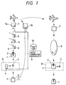
- Fig. 1 shows a conceptual arrangement of the embodiment of this invention.
- the baggage information such as the flight name, date and ID number (which is the number indicative of the baggage owner and which is registered together with the passenger in a host computer) is inputted in a response circuit 3 of a tag 2 through an issuing device of the tag 2 in accordance with the boarding ticket at a boarding counter A, and the information corresponding to the baggage information is also written in a surface of the tag 2.
- the tag 2 inputted is attached to a baggage 1 which is in turn conveyed through a belt conveyer 5, acting as a classifying device, after the baggage stub is handed to the passenger.
- a reader 6 transmits a question electromagnetic wave to the response circuit 3 which in turn transmits an answering electromagnetic wave to the reader 6 whereby the information of the tag 2 recorded in the response circuit 3 is provided to the reader 6.
- the baggage 1 is classified in connection with the aircraft into which the baggage 1 is loaded. This classification operation can continuously be effected without stopping the belt conveyer 5.
- the classified baggage 1 is encased in a container 7 and then loaded into the target aircraft.
- the baggage 1 is taken out from the aircraft and then placed on a belt conveyer 8 so as to be conveyed toward the passenger.
- the passenger carries the private baggage up to a baggage check counter B.
- the ID number written in the tag 2 attached to the baggage 1 is checked against the baggage stub of the passenger and the baggage 1 is delivered to the passenger.
- the response circuit 3 of the tag 2 is withdrawn in order to prevent the next classification operation from being impeded (due to interference).
- a plurality of containers 7 are prepared, and in encasing the containers 7 a reader reads the information indicative of the aircraft and container into which the baggage 1 is loaded and encased, and the read information is inputted through a terminal 9a in a host computer 9 and recorded in a data base 10.
- the baggage information is inputted through the issuing device 4 in the host computer 9, and further when the passenger gets on the aircraft, the information is inputted through a terminal 9b in the host computer 9.
- These information are recorded in the data base 10 so as to be used for the management of the baggage information which will be described hereinafter.
- Fig. 2 is a perspective view showing the state that the tag 2 is attached to the baggage 1
- Fig. 3 is a cross-sectional side view showing a structure of the tag 2.
- the tag 2 comprises three slips of paper: a main tag slip 11 attached to the baggage 1; a verification slip 12 for verifying the baggage owner; and a baggage slip (keeping slip) 13 delivered to the baggage owner, and further comprises the response circuit 3 for storing the baggage information.
- the slips 11 to 13 have on both surfaces writing columns a , b and c , respectively.
- the response circuit 3 is integrally caught by adhesives 14 provided between the paired slips 11 to 13 of the tag 2.
- the baggage slip 13 is cut away from the tag 2 and handed to the baggage owner.
- Fig. 4 shows a detailed arrangement of the response circuit 3.
- the response circuit 3 comprises an IC chip 31 for performing the internal signal processing, an antenna 32 for receiving a question electromagnetic wave S1 and transmitting a response electromagnetic wave S2, a battery 33 for driving the IC chip 31, an operation starting line 34 for stopping the operation of the response circuit 3 before start of using, and an operation ending line 35 for ending the operation of the response circuit 3 after the completion of using.
- the operation starting line 34 is provided within the baggage slip 13 and the operation ending line 35 is provided within the main tag slip 11.
- the IC chip 31 comprises a detector 31a for deriving the information included in the question electromagnetic wave S1 received through the antenna 32, a level comparator 31b for deciding the reception of the question electromagnetic wave S1 on the basis of the level of the signal from the detector 31a to supply a power to circuits, a memory 31c for storing the baggage information and others, a CPU 31d responsive to the power from the level comparator 31b to perform the transmission operation on the basis of the baggage information stored in the memory 31c, a clock generator 31e for generating a clock signal for the operation of the CPU 31d, a modulator 31f for modulating the question electromagnetic wave S1 on the basis of the output signal of the CPU 31d to transmit the response electromagnetic wave S2 through the antenna 32.
- punched holes 36a and 36b are formed by a punching device when the baggage information is written by the issuing device 4 which will be described hereinafter. With this formation of the punched holes 36a and 36b, the operation start line 34 is cut off whereby a drive circuit 31g starts to operate to start to operate the response circuit 3. Further, when the baggage information is written by the issuing device 4 at the boarding counter A, a writing command and the baggage information are given with respect to the first transmission signal from the issuing device 4 and the CPU 31d decides the writing of the baggage information in response to the reception of the writing command so that the baggage information is written in the memory 31c.
- the memory 31c is arranged to be operable immediately before the writing operation of the response circuit 3 so as to be backed up by the battery 33 to keep the baggage information.
- the level comparator 31b starts its power supply operation in response to the reception signal whereby the power is supplied to portions of the response circuit 3.
- the CPU 31d modulates the question electromagnetic wave S1 in accordance with the baggage information stored in the memory 31c to as to transmit the response electromagnetic wave S2 through the antenna 32.
- the operation ending line 35 provided within the main tag slip 11 is taken out whereby a discharging circuit 31h operates to discharge the power remaining in the battery 33.
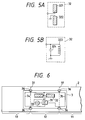
- Fig. 5A shows a dipole antenna comprising two antenna elements 321 and 322
- Fig. 5B shows a coil antenna comprising a coil 323 and a capacitor 324.
- the modulation and demodulation are effected with one antenna, it is appropriate to use two or more antennas which are respectively for the modulation and the demodulation.
- each of the aforementioned two antennas has at both front and back a directivity, it is possible to read out the information in the response circuit 3 from both front and back sides of the tag 2, whereby the baggage information can surely be read out irrespective of the direction of the tag 2 attached to the baggage 1 during the operation of the belt conveyer.
- the antenna 32 a different antenna such as a slot antenna if they have directivities at its front and back sides.
- the same two antennas such as microstrip patch antennas so that the two antennas are coupled to each other and disposed to be directed to both the front and back sides thereof.
- Fig. 6 shows the structure where the response circuit 3 is actually attached to the tag 2.
- the response circuit 3 spreads over the three slips: the main tag slip 11, the verification slip 12 and the baggage slip 13.
- a material such as polyester and paper which can easily be cut is used as a substrate material of the response circuit 3, and further cuts 36 are respectively made in the response circuit 36 and slittings 37 are formed in the tag 2.
- the cut 36 is for easy cutting, and hence it is also appropriate to entirely form fine notches at the circumferential portion of the response circuit 3 in place of the formation of the cuts 36.
- Fig. 7 in terms of an arrangement of the issuing device 4 for writing the baggage information in the response circuit 3 to issue the tag 2.
- the issuing device 4 is equipped with a keyboard 41 to input the baggage information.
- the baggage information is displayed on a display 42 and an operation is made for the verification of its contents, before the baggage information is supplied to the host computer 9 and further to a writer and a printer which will be described hereinbelow.
- a holder 43 for holding non-written tags 2 before writing the information.
- the non-written tags 2 are taken out one by one from the holder 43 and the punched holes 36a and 36b are formed at predetermined portions of the tag 2 in order to cut the operation starting line 34 of the tag 2.
- the baggage information is inputted through the keyboard 41 in a computer 48, and a writer 45 is operated under control of the computer 48 to write the baggage information in the response circuit 3 and a printer 46 is operated to print the baggage information on the surface of the tag 2.
- the tag 2 is derived from an output opening 47.
- all the necessary control are effected by the computer 48.
- it is not required that the information writing due to the writer 45 and the printing due to the printer 46 are simultaneously performed but it is appropriate that both are effected at different timings.
- Fig. 8 shows a detailed arrangement of the writer 45.
- the baggage information supplied from the computer 48 is inputted in the CPU 45a.
- the CPU 45a causes a modulator 45b to modulate a carrier wave from a carrier generator 45c in accordance with the inputted baggage information.
- This modulated signal is supplied through a circulator 45d to an antenna 45e so as to be transmitted as a transmission signal from the antenna 45e to the response circuit 3 of the tag 2.
- the response circuit 3 stores the baggage information in the memory 31c and then supplies a confirmation signal to the writer 45 after the completion of the storing operation.
- This confirmation signal is supplied through the antenna 45e and the circulator 45d to a demodulator 45f to be demodulated and further supplied to the CPU 45a.
- the reference 45g represents a clock generator for supplying clocks to the CPU 45a for the operation.
- the tag 2 issued by the aforementioned issuing device 4 is attached to the baggage 1 and automatically classified after the baggage slip 13 is handed to the passenger.
- the reader 6 transmits the question electromagnetic wave S1 in relation to the tag 2 of the baggage 1 and then inputs the response electromagnetic wave S2 from the response circuit 3 of the tag 2.
- the reader 6 reads the baggage information on the basis of the response electromagnetic wave S2 and, if satisfying the classification condition, rotationally drives a classifying plate 60 to discharge the baggage 1 from the belt conveyer 5. With this classifying operation being effected at every classifying point of the belt conveyer 5, it is possible to automatically classify the baggage 1 to the corresponding aircraft.
- Fig. 10 shows a detailed arrangement of the reader 6.
- the reader comprises an oscillator 61 for generating a transmission carrier wave, a modulator (MOD) 62 for producing the question wave S1 by modulating the carrier wave if required, a circulator 63 for performing the separation between the transmission wave and the reception wave, a transmission and reception antenna 64 for transmitting the question wave S1 and for receiving the response wave S2, a demodulator 65 for demodulating the received response wave S2, and a processing section for controlling the modulator 62 in accordance with the information from the demodulator 65 and further for deciding whether the baggage 1 satisfies the classification condition on the basis of the demodulated information so as to drive the classification plate 60 when satisfying the classification condition.
- the detailed arrangement shown in Fig. 10 is similar to the arrangement shown in Fig. 8.
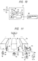
- Fig. 11 shows the state that each of 5 baggages 1a to 1e respectively having tags 2a to 2e are encased into either of three aircraft containers 7a to 7c which are loaded into the same aircraft.
- Three readers 71 to 73 are respectively disposed in front of the respective containers 7a to 7c so as to read the baggage information recorded in the response circuits 3a to 3e of the tags 2a to 2e attached to the baggages 1 to be encased (the arrangement of each of the readers 71 to 73 is basically similar to the arrangement shown in Fig. 10 except for the arrangement of the processing section 66 which transmits the demodulated information to the terminal 9a).
- the baggage information is supplied through the terminal 9a to the host computer 9 and the encasing information is stored in the data base 10.
- a reader 81 reads the baggage information from the response circuit 3 of the tag 2 and then displays the ID number (and/or the name of the owner obtained from ID number) and others on a display 82, whereby the passenger can check, in accordance with the display information, whether the baggage 1 is own.
- the verification slip 12 of the three tag slips is taken off from the main tag slip 11 and collected when the baggage 1 is handed to the owner.
- the response circuit 3 is built in the verification slip 12 of the tag 2
- the collection thereof becomes easy, thereby facilitating the re-use and abandonment.
- the verification slip 12 is taken off after the use of the tag 2 and the operation ending line 35 together with the verification slip 12 is also cut off from the IC chip 31 and further the remaining power of the battery 33 is discharged, it is possible to prevent the malfunction after the use.
- a registration operation of the baggage information from the issuing device 4 for issuing the tag 2 will be described.
- the operation starts with a step 101 to input the baggage information from the issuing device 4 through the terminal, then followed by a step 102 to define a file of the data base 10 in accordance with the boarding flight name and date of the baggage information.
- a step 103 follows to register the ID number at a storing area of the file corresponding to a baggage managing number (A) taken in order of issue. Accordingly, with the aforementioned operation being effected at every issue of the boarding pass, the ID number of the passenger is registered in the file corresponding to the boarding flight name and data in order of the baggage managing number (A).
- this operation starts with a step 201 to input through the terminal 9a the date and the flight name of the aircraft into which the container is loaded, then followed by a step 202 to select a file in the data base 10 on the basis of the input data. Further, a step 203 follows to input the number of a reader coupled to the terminal 9a and the number of a container for which the reader is placed. After the execution of these initial inputting processes, the following reading inputting operation is effected. That is, a step 204 first follows to check an input from either of the readers.
- a step 205 If not receiving the input, the decision of a step 205 is "NO", whereby the step 204 is repeatedly performed.
- the operational flow advances to a step 206 to check the number of the container corresponding to the number of the reader which generates the input and further advances to a step 207 to register the container number at the storing area of the file in the data base 10 which corresponds to the ID number of the read baggage information. This operation continues until all the baggages scheduled are loaded (step 208). Accordingly, with this operation, the number of the container for the baggage to be loaded in the aircraft, together with the ID number of the baggage, is registered in the file of the data base 10.
- the host computer 9 executes a step 301 to input the boarding ticket information from the terminal 9b and executes a step 302 to select the file of the data base on the basis of the inputted flight name and data and further executes a step 303 to write the board-end information (indicative of the fact that the boarding has been made) at the storing area of the file corresponding to the ID number.
- the board-end information is written in correspondence with the ID number of the passenger.
- a step 401 is first executed in order to input the aircraft flight name and date to be checked, then followed by a step 402 to select the corresponding file in accordance with the inputted data, thereafter performing the baggage check operation. That is, the first number of the baggage managing numbers (I) is set in a step 403 and the boarding of the passenger corresponding to the baggage managing number is checked in a baggage check routine 404. This check operation is effected through steps 405 and 406 with respect to all the baggage managing numbers.
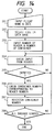
- Fig. 17 shows a detailed operation of the aforementioned baggage check routine 404.
- a step 404a is first executed to read the passenger information from the storing area corresponding to the baggage managing number in the file and a step 404b is then executed to check whether or not the baggage owner boards the aircraft. If the passenger does not get on, that is, if the answer of the step 404b is "NO", a step 404c follows to read the container number stored in correspondence with the managing number and a step 404d further follows to output a list indicative of the ID numbers of the baggage and the number of the container encasing the baggage to be taken out. Accordingly, by checking the ID number of the baggage encased in the container corresponding to the container number in accordance with the outputted list, it is possible to take out the baggage belonging to the person which does not get on.
- the information indicative of the number of the container in which one baggage is encased is additionally registered in the data base when the baggage is encased in the container, it is possible to roughly confirm the loaded position of the specific baggage in the container.
- Fig. 18 shows a response circuit 3 arranged such that the drive power is obtained from the question electromagnetic wave S1. Since this response circuit 3 is not equipped with a battery, unlike the above-described response circuit 3, the particular circuit for suppressing the consumption of the battery or effecting the consumption of the remaining power within the battery is not required.
- the response circuit 3 comprises an antenna 32 for receiving the question electromagnetic wave S1 and for transmitting the response electromagnetic wave S2, an IC chip 31 for performing the internal processing, and a writing terminal 31i for writing the baggage information in an internal memory.
- the IC chip 31 has a writable non-volatile memory PROM 31j which can keep the baggage information even when a power is not supplied thereto.
- a write signal or data is supplied from a writer through the writing terminal 31i thereto so that the baggage information is directly written in the PROM 31j.
- the terminal of the PROM 31j is directly controllable and hence it is not required to provide a special circuit or a CPU within the IC chip 31.
- the antenna 32 receives the question electromagnetic wave S1 from a reader and most of the reception signal is rectified by a detector 31a so as to be used as a direct-current power source for driving the circuits.
- a clock generator 31e and the PROM 31j within the IC chip 31 are driven to produce the response electromagnetic wave including the contents of the PROM 31j which is in turn transmitted through a modulator 31f toward the reader.
- the circuit is not cut at the time of the start of use or the end of use and the entire circuit is withdrawn together with the verification slip 12, and hence it is easily reusable.
- the tag 2 comprises an attaching portion 14 for coupling the tag 2 to the baggage 1, a pocket 15 and a tag slip 16 encased in the pocket 15, and the tag slip 15 comprises a printed seal having a surface to which the response circuit 3 is adhered.
- the response circuit 3 and the printed seal are adhered to each other by an adhesion whose degree is arranged to allow easy separation therebetween to permit the reuse.
- On the printed seal there is printed the information corresponding to baggage information stored in the response circuit 3.
Abstract
Description
- The present invention relates to an aircraft baggage managing system for managing baggages to be loaded into an aircraft.
- Generally, of baggages to be loaded into the aircraft, the baggages which are not brought in a cabin are encased in a container and loaded into the aircraft. Under such a situation, in case that one passenger does not get on the aircraft regardless of the fact that the passenger has checked a baggage, the specified baggage once encased in the aircraft container is required to be taken out from the aircraft. However, a conventional system does not have a function to sufficiently manage the baggage-loaded information, and hence difficulty is encountered to understand sorts of baggages actually loaded into the aircraft.
- It is therefore an object of the present invention to provide an aircraft baggage management system which is capable of automatically managing baggages to easily recognize the baggages loaded into the aircraft.
- In accordance with the present invention, there is provided a tag indicative of the fact that a baggage to be loaded into an aircraft belongs to a passenger which boards the aircraft, the tag including transmitting and receiving means comprising an antenna, a modulating and demodulating section and a signal processing section, the signal processing section storing baggage information representative of at least an owner of the baggage to which the tag is attached, and the transmitting and receiving means delivering the baggage information to an external through a reception and transmission of an electromagnetic wave.
- According to this invention, there is also provided an aircraft baggage managing system for computer-managing information of a baggage to be loaded in an aircraft, comprising: response circuit means attached to a tag for the baggage, the response circuit means storing the baggage information indicative of at least a flight name of the aircraft and an owner of the baggage to be loaded into the aircraft and further being responsive to a question electromagnetic wave to output as a response electromagnetic wave the baggage information; and reader means for transmitting the question electromagnetic wave to the response circuit means to read out the baggage information stored in the response circuit means through the response electromagnetic wave from the response circuit means when the baggage is encased in a container to be loaded into the aircraft, and for inputting the read baggage information in a computer.
- Further, according to this invention, there is provided an aircraft baggage managing system for managing information of a baggage to be loaded in an aircraft, comprising: response circuit means attached to the baggage, the response circuit means operating to input and store the baggage information indicative of at least a flight name of the aircraft and the owner of the baggage and further being responsive to a question electromagnetic wave to output as a response electromagnetic wave the baggage information; and reader means for transmitting the question electromagnetic wave to the response circuit means to receive the response electromagnetic wave from the response circuit means to read out the baggage information on the basis of the received response electromagnetic wave so that the baggage is classified in accordance with the read baggage information.
- The object and features of the present invention will become more readily apparent from the following detailed description of the preferred embodiments taken in conjunction with the accompanying drawings in which:
- Fig. 1 is an illustration of a schematic arrangement of an aircraft baggage managing system according to an embodiment of the present invention;
- Figs. 2 and 3 show an arrangement of a tag to be attached to a baggage to be loaded in an aircraft;
- Fig. 4 is a circuit diagram showing an arrangement of a response circuit attached to a baggage tag;
- Figs. 5A and 5B show different arrangement of an antenna constructed in the response circuit;
- Fig. 6 illustrates the state that the response circuit is attached to a baggage tag;
- Fig. 7 is an illustration of an arrangement of a tag issuing device;
- Fig. 8 is an illustration of an arrangement of a writer for writing baggage information in the response circuit;
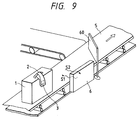
- Fig. 9 shows an arrangement of a classification device for classifying a baggage to which a tag is attached;
- Fig. 10 shows an arrangement of a reader for reading the baggage information from the response circuit;
- Fig. 11 shows a reading arrangement for reading the baggage information when the baggages are encased in a plurality of containers to be loaded into a corresponding aircraft;
- Fig. 12 shows a reading arrangement for reading the baggage information when the baggage is delivered to the baggage owner;
- Fig. 13 is a flow chart showing an operation to be executed for registering the baggage information when the tag is issued;
- Fig. 14 is a flow chart showing an operation to be executed for registering the baggage information when the baggage is encased in a container;
- Fig. 15 is a flow chart showing an operation to be executed when a passenger boards an aircraft;
- Fig. 16 is a flow chart showing an checking operation between a passenger and a baggage;
- Fig. 17 is a flow chart showing a detailed operation to be executed in a baggage check routine;
- Fig. 18 is a circuit diagram showing a different arrangement of the response circuit; and
- Fig. 19 shows a different arrangement of the tag.
- An embodiment of the present invention will be described hereinbelow with reference to the drawings. Fig. 1 shows a conceptual arrangement of the embodiment of this invention. In Fig. 1, first the baggage information such as the flight name, date and ID number (which is the number indicative of the baggage owner and which is registered together with the passenger in a host computer) is inputted in a
response circuit 3 of atag 2 through an issuing device of thetag 2 in accordance with the boarding ticket at a boarding counter A, and the information corresponding to the baggage information is also written in a surface of thetag 2. Further, thetag 2 inputted is attached to abaggage 1 which is in turn conveyed through abelt conveyer 5, acting as a classifying device, after the baggage stub is handed to the passenger. At each of the classifying points of thebelt conveyer 5, areader 6 transmits a question electromagnetic wave to theresponse circuit 3 which in turn transmits an answering electromagnetic wave to thereader 6 whereby the information of thetag 2 recorded in theresponse circuit 3 is provided to thereader 6. On the basis of the response information, thebaggage 1 is classified in connection with the aircraft into which thebaggage 1 is loaded. This classification operation can continuously be effected without stopping thebelt conveyer 5. Theclassified baggage 1 is encased in acontainer 7 and then loaded into the target aircraft. - After the aircraft arrives at the target airport, the
baggage 1 is taken out from the aircraft and then placed on abelt conveyer 8 so as to be conveyed toward the passenger. The passenger carries the private baggage up to a baggage check counter B. Here, the ID number written in thetag 2 attached to thebaggage 1 is checked against the baggage stub of the passenger and thebaggage 1 is delivered to the passenger. At this time, theresponse circuit 3 of thetag 2 is withdrawn in order to prevent the next classification operation from being impeded (due to interference). - Here, although a detailed illustration is not made, a plurality of
containers 7 are prepared, and in encasing the containers 7 a reader reads the information indicative of the aircraft and container into which thebaggage 1 is loaded and encased, and the read information is inputted through aterminal 9a in ahost computer 9 and recorded in adata base 10. In addition, in inputting the baggage information the baggage information is inputted through the issuingdevice 4 in thehost computer 9, and further when the passenger gets on the aircraft, the information is inputted through aterminal 9b in thehost computer 9. These information are recorded in thedata base 10 so as to be used for the management of the baggage information which will be described hereinafter. - Secondly, a description will be made in terms of a detailed arrangement of this embodiment. First, an arrangement of the
tag 2 will be described hereinbelow. Fig. 2 is a perspective view showing the state that thetag 2 is attached to thebaggage 1 and Fig. 3 is a cross-sectional side view showing a structure of thetag 2. In Figs. 2 and 3, thetag 2 comprises three slips of paper: amain tag slip 11 attached to thebaggage 1; averification slip 12 for verifying the baggage owner; and a baggage slip (keeping slip) 13 delivered to the baggage owner, and further comprises theresponse circuit 3 for storing the baggage information. Theslips 11 to 13 have on both surfaces writing columns a, b and c, respectively. Further, between therespective slips 11 to 13 there are made slittings or the like whereby theslips 11 to 13 are easily detachable from each other. In addition, theresponse circuit 3 is integrally caught byadhesives 14 provided between the pairedslips 11 to 13 of thetag 2. Thebaggage slip 13 is cut away from thetag 2 and handed to the baggage owner. - Secondly, a description will be made hereinbelow in terms of the
response circuit 3. Fig. 4 shows a detailed arrangement of theresponse circuit 3. In Fig. 4, theresponse circuit 3 comprises anIC chip 31 for performing the internal signal processing, anantenna 32 for receiving a question electromagnetic wave S1 and transmitting a response electromagnetic wave S2, abattery 33 for driving theIC chip 31, anoperation starting line 34 for stopping the operation of theresponse circuit 3 before start of using, and anoperation ending line 35 for ending the operation of theresponse circuit 3 after the completion of using. Theoperation starting line 34 is provided within thebaggage slip 13 and theoperation ending line 35 is provided within themain tag slip 11. Further, theIC chip 31 comprises adetector 31a for deriving the information included in the question electromagnetic wave S1 received through theantenna 32, alevel comparator 31b for deciding the reception of the question electromagnetic wave S1 on the basis of the level of the signal from thedetector 31a to supply a power to circuits, amemory 31c for storing the baggage information and others, aCPU 31d responsive to the power from thelevel comparator 31b to perform the transmission operation on the basis of the baggage information stored in thememory 31c, aclock generator 31e for generating a clock signal for the operation of theCPU 31d, amodulator 31f for modulating the question electromagnetic wave S1 on the basis of the output signal of theCPU 31d to transmit the response electromagnetic wave S2 through theantenna 32. - For use of the
response circuit 3, punchedholes device 4 which will be described hereinafter. With this formation of the punchedholes operation start line 34 is cut off whereby adrive circuit 31g starts to operate to start to operate theresponse circuit 3. Further, when the baggage information is written by the issuingdevice 4 at the boarding counter A, a writing command and the baggage information are given with respect to the first transmission signal from the issuingdevice 4 and theCPU 31d decides the writing of the baggage information in response to the reception of the writing command so that the baggage information is written in thememory 31c. Thememory 31c is arranged to be operable immediately before the writing operation of theresponse circuit 3 so as to be backed up by thebattery 33 to keep the baggage information. After the baggage information is written in thememory 31c, when theantenna 32 receives the question electromagnetic wave S1, thelevel comparator 31b starts its power supply operation in response to the reception signal whereby the power is supplied to portions of theresponse circuit 3. TheCPU 31d modulates the question electromagnetic wave S1 in accordance with the baggage information stored in thememory 31c to as to transmit the response electromagnetic wave S2 through theantenna 32. - Here, when the
verification slip 12 is cut off after the use of thetag 2, theoperation ending line 35 provided within themain tag slip 11 is taken out whereby a dischargingcircuit 31h operates to discharge the power remaining in thebattery 33. - As the
antenna 32 for theresponse circuit 3 there can be used an antenna as illustrated in Fig. 5A or 5B. Fig. 5A shows a dipole antenna comprising twoantenna elements coil 323 and acapacitor 324. Here, although in this embodiment the modulation and demodulation are effected with one antenna, it is appropriate to use two or more antennas which are respectively for the modulation and the demodulation. Since each of the aforementioned two antennas has at both front and back a directivity, it is possible to read out the information in theresponse circuit 3 from both front and back sides of thetag 2, whereby the baggage information can surely be read out irrespective of the direction of thetag 2 attached to thebaggage 1 during the operation of the belt conveyer. Further, it is appropriate to use as the antenna 32 a different antenna such as a slot antenna if they have directivities at its front and back sides. Moreover, it is also appropriate to use the same two antennas such as microstrip patch antennas so that the two antennas are coupled to each other and disposed to be directed to both the front and back sides thereof. - Fig. 6 shows the structure where the
response circuit 3 is actually attached to thetag 2. In Fig. 6, theresponse circuit 3 spreads over the three slips: themain tag slip 11, theverification slip 12 and thebaggage slip 13. For making easy separation of themain tag slip 11 and thebaggage slip 13 from theverification slip 12, a material such as polyester and paper which can easily be cut is used as a substrate material of theresponse circuit 3, andfurther cuts 36 are respectively made in theresponse circuit 36 andslittings 37 are formed in thetag 2. Here, thecut 36 is for easy cutting, and hence it is also appropriate to entirely form fine notches at the circumferential portion of theresponse circuit 3 in place of the formation of thecuts 36. - Further, a description will be made hereinbelow with reference to Fig. 7 in terms of an arrangement of the
issuing device 4 for writing the baggage information in theresponse circuit 3 to issue thetag 2. In Fig. 7, theissuing device 4 is equipped with akeyboard 41 to input the baggage information. When the baggage information is inputted through thekeyboard 41 in accordance with the information stated in the boarding ticket, the baggage information is displayed on adisplay 42 and an operation is made for the verification of its contents, before the baggage information is supplied to thehost computer 9 and further to a writer and a printer which will be described hereinbelow. - In addition, in the main portion of the
issuing device 4 there is provided aholder 43 for holdingnon-written tags 2 before writing the information. Thenon-written tags 2 are taken out one by one from theholder 43 and the punchedholes tag 2 in order to cut theoperation starting line 34 of thetag 2. Thereafter, the baggage information is inputted through thekeyboard 41 in acomputer 48, and awriter 45 is operated under control of thecomputer 48 to write the baggage information in theresponse circuit 3 and aprinter 46 is operated to print the baggage information on the surface of thetag 2. In response to the completion of the writing operation, thetag 2 is derived from anoutput opening 47. Here, all the necessary control are effected by thecomputer 48. Further, it is not required that the information writing due to thewriter 45 and the printing due to theprinter 46 are simultaneously performed but it is appropriate that both are effected at different timings. - Fig. 8 shows a detailed arrangement of the
writer 45. In Fig. 8, the baggage information supplied from thecomputer 48 is inputted in theCPU 45a. TheCPU 45a causes amodulator 45b to modulate a carrier wave from a carrier generator 45c in accordance with the inputted baggage information. This modulated signal is supplied through acirculator 45d to anantenna 45e so as to be transmitted as a transmission signal from theantenna 45e to theresponse circuit 3 of thetag 2. In response to the transmission signal, theresponse circuit 3 stores the baggage information in thememory 31c and then supplies a confirmation signal to thewriter 45 after the completion of the storing operation. This confirmation signal is supplied through theantenna 45e and thecirculator 45d to ademodulator 45f to be demodulated and further supplied to theCPU 45a. When detecting the reception thereof, theCPU 45a ends the writing operation with respect to theresponse circuit 3. Here, thereference 45g represents a clock generator for supplying clocks to theCPU 45a for the operation. - The
tag 2 issued by theaforementioned issuing device 4 is attached to thebaggage 1 and automatically classified after thebaggage slip 13 is handed to the passenger. - In addition, a description will be made hereinbelow in terms of an arrangement to automatically classify the baggage, having the
aforementioned tag 2, through thebelt conveyer 5. In Fig. 9, thereader 6 transmits the question electromagnetic wave S1 in relation to thetag 2 of thebaggage 1 and then inputs the response electromagnetic wave S2 from theresponse circuit 3 of thetag 2. Thereader 6 reads the baggage information on the basis of the response electromagnetic wave S2 and, if satisfying the classification condition, rotationally drives a classifyingplate 60 to discharge thebaggage 1 from thebelt conveyer 5. With this classifying operation being effected at every classifying point of thebelt conveyer 5, it is possible to automatically classify thebaggage 1 to the corresponding aircraft. - Fig. 10 shows a detailed arrangement of the
reader 6. In Fig. 10, for performing the aforementioned automatic classification, the reader comprises anoscillator 61 for generating a transmission carrier wave, a modulator (MOD) 62 for producing the question wave S1 by modulating the carrier wave if required, acirculator 63 for performing the separation between the transmission wave and the reception wave, a transmission andreception antenna 64 for transmitting the question wave S1 and for receiving the response wave S2, ademodulator 65 for demodulating the received response wave S2, and a processing section for controlling themodulator 62 in accordance with the information from thedemodulator 65 and further for deciding whether thebaggage 1 satisfies the classification condition on the basis of the demodulated information so as to drive theclassification plate 60 when satisfying the classification condition. Here, the detailed arrangement shown in Fig. 10 is similar to the arrangement shown in Fig. 8. - After the completion of the automatic classification, the
baggage 1 is encased in thecontainer 7. Fig. 11 shows the state that each of 5baggages 1a to 1e respectively havingtags 2a to 2e are encased into either of three aircraft containers 7a to 7c which are loaded into the same aircraft. Threereaders 71 to 73 are respectively disposed in front of the respective containers 7a to 7c so as to read the baggage information recorded in theresponse circuits 3a to 3e of thetags 2a to 2e attached to thebaggages 1 to be encased (the arrangement of each of thereaders 71 to 73 is basically similar to the arrangement shown in Fig. 10 except for the arrangement of theprocessing section 66 which transmits the demodulated information to the terminal 9a). The baggage information is supplied through the terminal 9a to thehost computer 9 and the encasing information is stored in thedata base 10. - After the aircraft arrives at the destination, the
baggages 1 are delivered through thebelt conveyer 8 toward the passengers. Here, as illustrated in Fig. 12, similarly, areader 81 reads the baggage information from theresponse circuit 3 of thetag 2 and then displays the ID number (and/or the name of the owner obtained from ID number) and others on adisplay 82, whereby the passenger can check, in accordance with the display information, whether thebaggage 1 is own. - Further, at the tag check counter B, the
verification slip 12 of the three tag slips is taken off from themain tag slip 11 and collected when thebaggage 1 is handed to the owner. Thus, since theresponse circuit 3 is built in theverification slip 12 of thetag 2, the collection thereof becomes easy, thereby facilitating the re-use and abandonment. In addition, since theverification slip 12 is taken off after the use of thetag 2 and theoperation ending line 35 together with theverification slip 12 is also cut off from theIC chip 31 and further the remaining power of thebattery 33 is discharged, it is possible to prevent the malfunction after the use. - A description will be made hereinbelow in terms of the management of the baggage information by the
host computer 9. First, a registration operation of the baggage information from theissuing device 4 for issuing thetag 2 will be described. In Fig. 13, the operation starts with astep 101 to input the baggage information from theissuing device 4 through the terminal, then followed by astep 102 to define a file of thedata base 10 in accordance with the boarding flight name and date of the baggage information. Further, astep 103 follows to register the ID number at a storing area of the file corresponding to a baggage managing number (A) taken in order of issue. Accordingly, with the aforementioned operation being effected at every issue of the boarding pass, the ID number of the passenger is registered in the file corresponding to the boarding flight name and data in order of the baggage managing number (A). - Secondly, a description will be made hereinbelow in terms of a registration operation at the time of the encasing into the container. In Fig. 14, this operation starts with a
step 201 to input through the terminal 9a the date and the flight name of the aircraft into which the container is loaded, then followed by astep 202 to select a file in thedata base 10 on the basis of the input data. Further, astep 203 follows to input the number of a reader coupled to the terminal 9a and the number of a container for which the reader is placed. After the execution of these initial inputting processes, the following reading inputting operation is effected. That is, astep 204 first follows to check an input from either of the readers. If not receiving the input, the decision of astep 205 is "NO", whereby thestep 204 is repeatedly performed. On the other hand, if the input from the reader occurs, the operational flow advances to astep 206 to check the number of the container corresponding to the number of the reader which generates the input and further advances to astep 207 to register the container number at the storing area of the file in thedata base 10 which corresponds to the ID number of the read baggage information. This operation continues until all the baggages scheduled are loaded (step 208). Accordingly, with this operation, the number of the container for the baggage to be loaded in the aircraft, together with the ID number of the baggage, is registered in the file of thedata base 10. - Further, a description will be made hereinbelow in terms of a registration operation effected when the passenger gets on the corresponding aircraft. At a gate used when the passenger loads thereinto there is provided the terminal 9b which is for inputting the boarding flight name, date and ID number on the basis of the boarding ticket of the passenger. In Fig. 15, the
host computer 9 executes astep 301 to input the boarding ticket information from the terminal 9b and executes astep 302 to select the file of the data base on the basis of the inputted flight name and data and further executes astep 303 to write the board-end information (indicative of the fact that the boarding has been made) at the storing area of the file corresponding to the ID number. Thus, in the file the board-end information is written in correspondence with the ID number of the passenger. - The verification between the passenger and the baggage is made in accordance with the above-described various registration information. This operation will be described hereinbelow with reference to Fig. 16. In Fig. 16, a
step 401 is first executed in order to input the aircraft flight name and date to be checked, then followed by astep 402 to select the corresponding file in accordance with the inputted data, thereafter performing the baggage check operation. That is, the first number of the baggage managing numbers (I) is set in astep 403 and the boarding of the passenger corresponding to the baggage managing number is checked in abaggage check routine 404. This check operation is effected throughsteps - Fig. 17 shows a detailed operation of the aforementioned
baggage check routine 404. Astep 404a is first executed to read the passenger information from the storing area corresponding to the baggage managing number in the file and astep 404b is then executed to check whether or not the baggage owner boards the aircraft. If the passenger does not get on, that is, if the answer of thestep 404b is "NO", astep 404c follows to read the container number stored in correspondence with the managing number and astep 404d further follows to output a list indicative of the ID numbers of the baggage and the number of the container encasing the baggage to be taken out. Accordingly, by checking the ID number of the baggage encased in the container corresponding to the container number in accordance with the outputted list, it is possible to take out the baggage belonging to the person which does not get on. - Here, if the information indicative of the number of the container in which one baggage is encased is additionally registered in the data base when the baggage is encased in the container, it is possible to roughly confirm the loaded position of the specific baggage in the container.
- A description will be made hereinbelow in terms of a different arrangement of the
response circuit 3. Fig. 18 shows aresponse circuit 3 arranged such that the drive power is obtained from the question electromagnetic wave S1. Since thisresponse circuit 3 is not equipped with a battery, unlike the above-describedresponse circuit 3, the particular circuit for suppressing the consumption of the battery or effecting the consumption of the remaining power within the battery is not required. - In Fig. 18, the
response circuit 3 comprises anantenna 32 for receiving the question electromagnetic wave S1 and for transmitting the response electromagnetic wave S2, anIC chip 31 for performing the internal processing, and awriting terminal 31i for writing the baggage information in an internal memory. Further, theIC chip 31 has a writablenon-volatile memory PROM 31j which can keep the baggage information even when a power is not supplied thereto. For writing the baggage information in theresponse circuit 3, a write signal or data is supplied from a writer through the writingterminal 31i thereto so that the baggage information is directly written in thePROM 31j. At this time, the terminal of thePROM 31j is directly controllable and hence it is not required to provide a special circuit or a CPU within theIC chip 31. Further, for reading the written information, theantenna 32 receives the question electromagnetic wave S1 from a reader and most of the reception signal is rectified by adetector 31a so as to be used as a direct-current power source for driving the circuits. Thus, aclock generator 31e and thePROM 31j within theIC chip 31 are driven to produce the response electromagnetic wave including the contents of thePROM 31j which is in turn transmitted through amodulator 31f toward the reader. - According to this arrangement, the circuit is not cut at the time of the start of use or the end of use and the entire circuit is withdrawn together with the
verification slip 12, and hence it is easily reusable. In addition, it is possible to increase the degree of freedom when attaching theresponse circuit 3 to thetag 2, and hence it is also possible to arrange thetag 2 as illustrated in Fig. 19. That is, thetag 2 comprises an attachingportion 14 for coupling thetag 2 to thebaggage 1, apocket 15 and atag slip 16 encased in thepocket 15, and thetag slip 15 comprises a printed seal having a surface to which theresponse circuit 3 is adhered. Here, theresponse circuit 3 and the printed seal are adhered to each other by an adhesion whose degree is arranged to allow easy separation therebetween to permit the reuse. On the printed seal there is printed the information corresponding to baggage information stored in theresponse circuit 3. - It should be understood that the foregoing relates to only preferred embodiments of the present invention, and that it is intended to cover all changes and modifications of the embodiments of the invention herein used for the purposes of the disclosure, which do not constitute departures from the spirit and scope of the invention. For example, although the above-described embodiment relates to the computer management for the verification between the passenger and the baggage, it is appropriate that this invention is applied to a baggage tracing system operated in case that one baggage is not loaded into a given aircraft.
Claims (16)
- A tag indicative of the fact that a baggage to be loaded into an aircraft belongs to a passenger which boards said aircraft, said tag including transmitting and receiving means comprising an antenna, a modulating and demodulating section and a signal processing section, said signal processing section storing baggage information representative of at least an owner of said baggage to which said tag is attached, and said transmitting and receiving means delivering said baggage information to an external through a reception and transmission of an electromagnetic wave.
- A tag as claimed in claim 1, further including a main tag slip, a verification slip for verifying said baggage and said owner of said baggage, and a keeping slip to be handed to said owner of said baggage, said transmitting and receiving means being encased in at least verification slip.
- A tag as claimed in claim 2, wherein a portion of said transmitting and receiving means is encased in said main tag slip and the remaining portion thereof is encased in said verification slip, and after a completion of a verification due to said verification slip, said verification slip is cut off from said tag so that the transmission and reception of said electromagnetic wave becomes incompetent.
- A tag as claimed in claim 3, wherein said transmitting and receiving means comprises power supply means for supplying a power to said signal processing section and discharging means for discharging the power within said power supply means, and said discharging means starts to discharge the power within said power supply means when said verification slip is cut off from said tag after the completion of said verification due to said verification slip.
- A tag as claimed in claim 1, wherein said transmitting and receiving means comprises power supply means for supplying a power to said signal processing section and supply starting means for starting the power supply due to said power supply means.
- A tag as claimed in claim 5, further comprising a keeping slip so that said supply starting means starts the power supply when said keeping slip is cut off from said tag.
- An aircraft baggage managing system for computer-managing information of a baggage to be loaded in an aircraft, comprising:
response circuit means attached to a tag for said baggage, said response circuit means storing said baggage information indicative of at least a flight name of said aircraft and an owner of said baggage to be loaded into said aircraft and further being responsive to a question electromagnetic wave to output as a response electromagnetic wave said baggage information; and
reader means for transmitting said question electromagnetic wave to said response circuit means to read out said baggage information stored in said response circuit means through said response electromagnetic wave from said response circuit means when said baggage is encased in a container to be loaded into said aircraft, and for inputting the read baggage information in a computer. - A system as claimed in claim 7, wherein said reader means is pluralized in correspondence with a plurality of containers to be loaded into said aircraft so that the plurality of reader means read said baggage information to further manage, by said computer, information representative of one of said plurality of containers in which said baggage is encased.
- A system as claimed in claim 7, further comprising means for inputting passenger information in said computer when a passenger boards said aircraft and means included in said computer for detecting a verification between said baggage to be loaded into said aircraft and said passenger boarding said aircraft on the basis of the read baggage information and the inputted passenger information.
- An aircraft baggage managing system for managing information of a baggage to be loaded in an aircraft, comprising:
response circuit means attached to said baggage, said response circuit means operating to input and store said baggage information indicative of at least a flight name of said aircraft and said owner of said baggage and further being responsive to a question electromagnetic wave to output as a response electromagnetic wave said baggage information; and
reader means for transmitting said question electromagnetic wave to said response circuit means to receive said response electromagnetic wave from said response circuit means to read out said baggage information on the basis of the received response electromagnetic wave so that said baggage is classified in accordance with the read baggage information. - A system as claimed in claim 10, wherein said response circuit means is attached to a tag to be attached to said baggage, said tag having a verification slip to be handed to said owner of said baggage in which information corresponding to said baggage information is written.
- A system as claimed in claim 11, wherein said response circuit means has means for stopping the operation of said response circuit means when said verification slip is removed from said tag.
- A system as claimed in claim 12, wherein said response circuit means has means for starting the operation of said response circuit means when a portion of said tag is cut.
- A system as claimed in claim 11, wherein said response circuit means has power supply means for supplying a power to elements constituting said response circuit means and further has means for discharging the remaining power of said power supply means when said verification slip is removed from said tag.
- A system as claimed in claim 10, wherein said response circuit means includes means for producing a power on the basis of said question electromagnetic wave from said reader means, said power being supplied to constituting elements of said response circuit means whereby said response circuit means outputs said response electromagnetic wave to said reader means.
- A system as claimed in claim 10, further comprising a computer for inputting and storing said baggage information read by said reader means and for inputting and storing information representative of said owner of said baggage, said computer performing a verification between said baggage owner and said baggage on the basis of the inputted baggage information and the inputted owner information.
Applications Claiming Priority (2)
| Application Number | Priority Date | Filing Date | Title |
|---|---|---|---|
| JP158617/91 | 1991-06-28 | ||
| JP3158617A JP2993186B2 (en) | 1991-06-28 | 1991-06-28 | Aircraft baggage management system |
Publications (3)
| Publication Number | Publication Date |
|---|---|
| EP0520455A2 true EP0520455A2 (en) | 1992-12-30 |
| EP0520455A3 EP0520455A3 (en) | 1993-06-09 |
| EP0520455B1 EP0520455B1 (en) | 1996-11-13 |
Family
ID=15675628
Family Applications (1)
| Application Number | Title | Priority Date | Filing Date |
|---|---|---|---|
| EP92110747A Expired - Lifetime EP0520455B1 (en) | 1991-06-28 | 1992-06-25 | Aircraft baggage managing system |
Country Status (4)
| Country | Link |
|---|---|
| US (2) | US5313052A (en) |
| EP (1) | EP0520455B1 (en) |
| JP (1) | JP2993186B2 (en) |
| DE (1) | DE69215150T2 (en) |
Cited By (18)
| Publication number | Priority date | Publication date | Assignee | Title |
|---|---|---|---|---|
| WO1995016214A1 (en) * | 1993-12-10 | 1995-06-15 | SIEMENS AKTIENGESELLSCHAFT öSTERREICH | Data medium for identifying objects and process for its control |
| WO1997013685A1 (en) * | 1995-10-06 | 1997-04-17 | The Adi Group Limited | A monitoring system |
| EP0777890A1 (en) * | 1994-08-25 | 1997-06-11 | Geefield Pty. Ltd. | Method and apparatus for providing identification |
| WO1998015921A1 (en) * | 1996-10-04 | 1998-04-16 | Geoffrey Stringer Hunter | Passenger/luggage movement control security systems |
| EP0933751A1 (en) * | 1998-01-29 | 1999-08-04 | Maikranz, Friedhelm | Device to identify baggage |
| EP0940763A1 (en) * | 1996-12-31 | 1999-09-08 | Lucent Technologies Inc. | Passsenger, baggage, and cargo reconciliation system |
| FR2779545A1 (en) * | 1998-06-08 | 1999-12-03 | Skysafe System | METHOD AND DEVICE FOR CONTROLLING THE INTEGRITY OF LUGGAGE FROM BOARDING TO LANDING |
| WO2002000530A1 (en) * | 2000-06-24 | 2002-01-03 | Der Grüne Punkt-Duales System Deutschland Ag | Method for tracking waste |
| EP1172759A1 (en) | 2000-07-11 | 2002-01-16 | X-ident GmbH | Security label having a built-in RFID-transponder |
| EP1146463A3 (en) * | 2000-04-12 | 2002-12-04 | Hudson Soft Co., Ltd. | Baggage managing system in airport |
| WO2003022683A1 (en) * | 2001-09-11 | 2003-03-20 | Eds-Te.Ma S.R.L. | Method for identifying packages in transit |
| DE19824323B4 (en) * | 1998-06-02 | 2004-01-29 | Mvs-Imci Maschinen- Und Verpackungs-Service Gmbh | Method for monitoring the passage of a group of independent objects through a passage area and monitoring system |
| WO2004074100A1 (en) * | 2003-02-18 | 2004-09-02 | Tagmaster Ab | Method at loading and unloading of goods in aircrafts |
| WO2004074099A1 (en) * | 2003-02-18 | 2004-09-02 | Tagmaster Ab | Method at loading and unloading aircrafts |
| WO2009098439A3 (en) * | 2008-02-05 | 2009-11-12 | Baa (Ip Holdco) Limited | Baggage system |
| WO2012113522A1 (en) * | 2011-02-21 | 2012-08-30 | Giesecke & Devrient Gmbh | Commissioning a portable data storage medium |
| FR2975078A1 (en) * | 2011-05-13 | 2012-11-16 | Sbs | TRANSFER INSTALLATION FOR AIR TRANSPORT |
| WO2015011426A1 (en) * | 2013-07-25 | 2015-01-29 | Sbs | Luggage handling control installation |
Families Citing this family (119)
| Publication number | Priority date | Publication date | Assignee | Title |
|---|---|---|---|---|
| US5869819A (en) * | 1994-08-17 | 1999-02-09 | Metrologic Instuments Inc. | Internet-based system and method for tracking objects bearing URL-encoded bar code symbols |
| USRE42773E1 (en) | 1992-06-17 | 2011-10-04 | Round Rock Research, Llc | Method of manufacturing an enclosed transceiver |
| US7158031B2 (en) * | 1992-08-12 | 2007-01-02 | Micron Technology, Inc. | Thin, flexible, RFID label and system for use |
| GB9306805D0 (en) * | 1993-04-01 | 1993-05-26 | Jonhig Ltd | Smart card reader |
| DE69323293T2 (en) * | 1993-04-14 | 1999-09-09 | Gustafson | Electronic marking device |
| JPH06318277A (en) * | 1993-05-06 | 1994-11-15 | Chuo Denshi Kk | Method for managing entrance/exit of passenger and checked baggage in airport |
| US5430441A (en) * | 1993-10-12 | 1995-07-04 | Motorola, Inc. | Transponding tag and method |
| US5469363A (en) * | 1994-05-19 | 1995-11-21 | Saliga; Thomas V. | Electronic tag with source certification capability |
| US7712668B2 (en) | 1994-05-25 | 2010-05-11 | Marshall Feature Recognition, Llc | Method and apparatus for accessing electronic data via a familiar printed medium |
| US8910876B2 (en) | 1994-05-25 | 2014-12-16 | Marshall Feature Recognition, Llc | Method and apparatus for accessing electronic data via a familiar printed medium |
| US6866196B1 (en) | 1994-05-25 | 2005-03-15 | Spencer A. Rathus | Method and apparatus for accessing electronic data via a familiar printed medium |
| US8261993B2 (en) | 1994-05-25 | 2012-09-11 | Marshall Feature Recognition, Llc | Method and apparatus for accessing electronic data via a familiar printed medium |
| JPH0844914A (en) * | 1994-08-03 | 1996-02-16 | Matsushita Electric Ind Co Ltd | Package management system |
| CA2199041A1 (en) * | 1994-09-02 | 1996-03-14 | Victor Chartrand | Multimedia golf handicap interactive touch-screen system with electronic card |
| DK0787334T3 (en) | 1994-10-14 | 1999-05-03 | United Parcel Service Inc | Multistage packet tracking system |
| US5752234A (en) * | 1995-08-18 | 1998-05-12 | Patient Solutions | Method and apparatus for managing disposable medical supplies appropriate for a single patient visit |
| JP3267489B2 (en) * | 1995-11-09 | 2002-03-18 | 富士通株式会社 | Transit information management method and system |
| US5591951A (en) * | 1995-10-12 | 1997-01-07 | The Regents Of The University Of California | System and method for simultaneously collecting serial number information from numerous identity tags |
| US5870711A (en) * | 1995-12-11 | 1999-02-09 | Sabre Properties, Inc. | Method and system for management of cargo claims |
| JP3565967B2 (en) * | 1995-12-21 | 2004-09-15 | 富士通株式会社 | IC card reading / writing device and IC card system |
| US5804802A (en) * | 1996-02-14 | 1998-09-08 | United Parcel Service Of America, Inc. | Two-way data communication manager |
| US6774685B2 (en) | 1996-05-13 | 2004-08-10 | Micron Technology, Inc. | Radio frequency data communications device |
| US6836468B1 (en) | 1996-05-13 | 2004-12-28 | Micron Technology, Inc. | Radio frequency data communications device |
| US6696879B1 (en) | 1996-05-13 | 2004-02-24 | Micron Technology, Inc. | Radio frequency data communications device |
| US6941124B1 (en) | 1996-05-13 | 2005-09-06 | Micron Technology, Inc. | Method of speeding power-up of an amplifier, and amplifier |
| US6130602A (en) | 1996-05-13 | 2000-10-10 | Micron Technology, Inc. | Radio frequency data communications device |
| EP1372106B1 (en) * | 1996-08-09 | 2006-10-04 | Ferag AG | System comprising roll cores with roll bands and a reading/writing device for non-contact reading and/or overwriting of data |
| US5814797A (en) * | 1996-11-04 | 1998-09-29 | A Rifkin Co. | Transponder system for monitoring and logging depository transactions |
| US5949059A (en) * | 1996-12-09 | 1999-09-07 | International Business Machines Corporation | Tamper evident labelling system with embedded storage device |
| US6611733B1 (en) * | 1996-12-20 | 2003-08-26 | Carlos De La Huerga | Interactive medication dispensing machine |
| JP3315884B2 (en) * | 1996-12-27 | 2002-08-19 | 株式会社日立製作所 | Airport integrated IC card system |
| US6046683A (en) * | 1996-12-31 | 2000-04-04 | Lucent Technologies Inc. | Modulated backscatter location system |
| US6456668B1 (en) | 1996-12-31 | 2002-09-24 | Lucent Technologies Inc. | QPSK modulated backscatter system |
| US5962834A (en) * | 1997-03-17 | 1999-10-05 | Markman; Herbert L. | Inventory tracking and management apparatus with multi-function encoding unit |
| JP4143158B2 (en) * | 1997-04-16 | 2008-09-03 | 聯華電子股▲ふん▼有限公司 | Data carrier |
| US5971587A (en) * | 1997-08-01 | 1999-10-26 | Kato; Kiroku | Package and mail delivery system |
| US6980085B1 (en) * | 1997-08-18 | 2005-12-27 | Micron Technology, Inc. | Wireless communication devices and methods of forming and operating the same |
| US6339385B1 (en) | 1997-08-20 | 2002-01-15 | Micron Technology, Inc. | Electronic communication devices, methods of forming electrical communication devices, and communication methods |
| US6158658A (en) * | 1997-08-27 | 2000-12-12 | Laser Data Command, Inc. | System and method for matching passengers and their baggage |
| US6393045B1 (en) | 1997-09-26 | 2002-05-21 | Wherenet Corp. | Spread spectrum baseband modulation of magnetic fields for communications and proximity sensing |
| US7216802B1 (en) * | 1997-10-21 | 2007-05-15 | Carlos De La Huerga | Method and apparatus for verifying information |
| US6002344A (en) * | 1997-11-21 | 1999-12-14 | Bandy; William R. | System and method for electronic inventory |
| US7844505B1 (en) | 1997-11-21 | 2010-11-30 | Symbol Technologies, Inc. | Automated real-time distributed tag reader network |
| US7035818B1 (en) | 1997-11-21 | 2006-04-25 | Symbol Technologies, Inc. | System and method for electronic inventory |
| US6030423A (en) * | 1998-02-12 | 2000-02-29 | Micron Technology, Inc. | Thin profile battery bonding method and method of conductively interconnecting electronic components |
| US6609656B1 (en) * | 1998-03-27 | 2003-08-26 | Micron Technology, Inc. | Method and system for identifying lost or stolen devices |
| FR2776797B1 (en) * | 1998-03-30 | 2000-06-30 | Gemplus Card Int | CONTACTLESS INTEGRATED CIRCUIT CARD WITH MEANS OF INHIBITION |
| JPH11349132A (en) * | 1998-06-08 | 1999-12-21 | Nippon Lsi Card Co Ltd | Article carrier method, distribution system and carrier bag used for them |
| US8052061B2 (en) * | 2002-08-07 | 2011-11-08 | Vanguard Identification Systems, Inc. | Permanent RFID luggage tag with security features |
| US7845569B1 (en) | 1999-06-16 | 2010-12-07 | Vanguard Identification Systems, Inc. | Permanent RFID luggage tag with security features |
| US7204652B2 (en) * | 1999-06-16 | 2007-04-17 | Vanguard Identification Systems, Inc. | Printed planar radio frequency identification elements |
| US8654018B2 (en) * | 2005-04-06 | 2014-02-18 | Vanguard Identificaiton Systems, Inc. | Printed planar RFID element wristbands and like personal identification devices |
| US8585852B2 (en) * | 1999-06-16 | 2013-11-19 | Vanguard Identification Systems, Inc. | Methods of making printed planar radio frequency identification elements |
| US6994262B1 (en) * | 1999-06-16 | 2006-02-07 | Vanguard Identification Systems, Inc. | Printed sheet products with integral, removable, radio frequency identification elements |
| DE19934095A1 (en) * | 1999-07-21 | 2001-01-25 | Abb Patent Gmbh | Process and arrangement for the automated transport, sorting and loading of luggage |
| JP2001043336A (en) * | 1999-07-29 | 2001-02-16 | Sony Chem Corp | Ic card |
| US6976007B1 (en) | 1999-10-04 | 2005-12-13 | Pitney Bowes Inc. | Method and system for multi-carrier package tracking |
| US6963861B1 (en) | 1999-10-04 | 2005-11-08 | Pitney Bowes Inc. | Method and system for resolution of carrier specific data utilizing a generic data model |
| US6698653B1 (en) | 1999-10-28 | 2004-03-02 | Mel Diamond | Identification method, especially for airport security and the like |
| US7401030B1 (en) * | 1999-12-30 | 2008-07-15 | Pitney Bowes Inc. | Method and system for tracking disposition status of an item to be delivered within an organization |
| DE10007127A1 (en) * | 2000-02-17 | 2001-08-23 | Hugues Edwin Luedi | Flight passenger and luggage checking-in method in airport, involves storing personal and traveling details of passenger along with his fingerprint data in memory chip installed in his luggage |
| US6342836B2 (en) * | 2000-02-25 | 2002-01-29 | Harry I. Zimmerman | Proximity and sensing system for baggage |
| JP2001240218A (en) * | 2000-02-28 | 2001-09-04 | Dainippon Printing Co Ltd | Automatic air cargo sorting, delivery system, automatic air cargo receiving system and ic baggage tag |
| US6369710B1 (en) | 2000-03-27 | 2002-04-09 | Lucent Technologies Inc. | Wireless security system |
| WO2001084470A2 (en) * | 2000-05-02 | 2001-11-08 | Supercom Ltd. | Upgrading conventional documents to smart documents |
| US6807458B2 (en) * | 2000-09-20 | 2004-10-19 | Steve Quackenbush | Baggage transportation security system |
| US7098793B2 (en) * | 2000-10-11 | 2006-08-29 | Avante International Technology, Inc. | Tracking system and method employing plural smart tags |
| US6883710B2 (en) * | 2000-10-11 | 2005-04-26 | Amerasia International Technology, Inc. | Article tracking system and method |
| US6989750B2 (en) * | 2001-02-12 | 2006-01-24 | Symbol Technologies, Inc. | Radio frequency identification architecture |
| JP2002255340A (en) * | 2001-02-28 | 2002-09-11 | Toshiba It & Control Systems Corp | Cargo sorting system |
| JP4727055B2 (en) * | 2001-03-15 | 2011-07-20 | 日本信号株式会社 | Goods management system |
| EP1374183A4 (en) * | 2001-03-23 | 2009-03-18 | Sabre Inc | Systems and methods for event driven baggage management |
| MXPA03010741A (en) * | 2001-05-21 | 2005-03-07 | Scott Lab Inc | Rf-id laberl for a medical container. |
| US20060243799A1 (en) * | 2001-10-22 | 2006-11-02 | Maximus, Inc., | Method and apparatus for providing heightened airport security |
| DE10156038A1 (en) * | 2001-11-15 | 2003-06-05 | Joergen Brosow | Aviation security procedures |
| US7023356B2 (en) | 2001-11-26 | 2006-04-04 | Aero-Vision Technologies, Inc. | System and method for monitoring individuals and objects associated with wireless identification tags |
| US20030225612A1 (en) * | 2002-02-12 | 2003-12-04 | Delta Air Lines, Inc. | Method and system for implementing security in the travel industry |
| US7009496B2 (en) * | 2002-04-01 | 2006-03-07 | Symbol Technologies, Inc. | Method and system for optimizing an interrogation of a tag population |
| US6724306B1 (en) | 2002-06-21 | 2004-04-20 | Ralph O. Parsley, Jr. | Luggage locating system |
| CA2397501A1 (en) * | 2002-08-19 | 2004-02-19 | Emerson Nerat | Wireless smart system for tracking luggage |
| US20040129769A1 (en) * | 2002-10-09 | 2004-07-08 | Aram Kovach | Method for identifying and tracking test specimens |
| US20040143505A1 (en) * | 2002-10-16 | 2004-07-22 | Aram Kovach | Method for tracking and disposition of articles |
| US6970088B2 (en) * | 2002-10-17 | 2005-11-29 | Compex, Inc. | Method for tracking and processing passengers and their transported articles |
| JP2006504334A (en) * | 2002-10-25 | 2006-02-02 | シンボル テクノロジーズ, インコーポレイテッド | Optimize binary tree transversal with secure communication |
| US20040124239A1 (en) * | 2002-12-14 | 2004-07-01 | Mark Feld | Label system and method for returning lost articles |
| US20050088320A1 (en) * | 2003-10-08 | 2005-04-28 | Aram Kovach | System for registering and tracking vehicles |
| EP1760900B1 (en) * | 2004-06-10 | 2011-04-06 | Panasonic Corporation | Rfid tag and rfid tag communication distance modification method |
| WO2007037778A2 (en) * | 2004-09-03 | 2007-04-05 | Societe De Technologie Michelin | Improved method for curing a thick, non-uniform rubber article |
| DE102004051938B4 (en) * | 2004-10-25 | 2008-02-28 | Deutsche Post Ag | Method and device for checking the loading of a transport device with objects |
| US20060170556A1 (en) * | 2005-01-18 | 2006-08-03 | Lexin Technology Inc. | System for detecting an RFID tag |
| AU2006230238A1 (en) * | 2005-03-29 | 2006-10-05 | Symbol Technologies, Inc. | Smart radio frequency identification (RFID) items |
| CN100410960C (en) * | 2005-04-06 | 2008-08-13 | 雷新科技股份有限公司 | System for detecting RF identification label |
| EP2002697A1 (en) * | 2006-04-03 | 2008-12-17 | Siemens Enterprise Communications GmbH & Co. KG | Electronic module and procedure for at least the partial scrapping of the electronic module |
| JP5128802B2 (en) * | 2006-10-27 | 2013-01-23 | 学校法人田村学園 | Aircraft container |
| EP1939794A3 (en) | 2006-12-29 | 2009-04-01 | Vanguard Identification Systems, Inc. | Printed planar RFID element wristbands and like personal identification devices |
| JP5040450B2 (en) * | 2007-06-04 | 2012-10-03 | 大日本印刷株式会社 | RFID tag communication system for baggage |
| US20090315704A1 (en) * | 2008-06-19 | 2009-12-24 | Global Biomedical Development, Llc, A Georgia Limited Liability Company | Method and Integrated System for Tracking Luggage |
| US20100013211A1 (en) * | 2008-07-16 | 2010-01-21 | Syed Masood Ahmed | Identification tag |
| US9224084B2 (en) | 2009-04-01 | 2015-12-29 | Vanguard Identification Systems, Inc. | Smart device programmable electronic luggage tag |
| US9918537B2 (en) | 2009-04-01 | 2018-03-20 | Vanguard Identification Systems | Smart device programmable electronic luggage tag and bag mountings therefore |
| CN103348362A (en) * | 2009-07-24 | 2013-10-09 | 可视化解决方案私人有限公司 | Wireless detectable tamper evident seal |
| US20110267192A1 (en) * | 2010-04-28 | 2011-11-03 | Alcatel-Lucent Usa Inc. | Individualized Baggage Tracking And Notification System |
| JP5621367B2 (en) * | 2010-07-12 | 2014-11-12 | 株式会社デンソーウェーブ | Baggage management system |
| JP4839416B1 (en) | 2011-01-06 | 2011-12-21 | アクアエンタープライズ株式会社 | Movement process prediction system, movement process prediction method, movement process prediction apparatus, and computer program |
| JP5174993B2 (en) * | 2011-01-06 | 2013-04-03 | アクアエンタープライズ株式会社 | Movement status detection system |
| JP5664423B2 (en) * | 2011-04-11 | 2015-02-04 | 大日本印刷株式会社 | Sampling management system and method |
| MY151548A (en) * | 2011-08-03 | 2014-06-06 | Sita Inf Networking Computing Usa Inc | Item handling and tracking system and method thereof |
| US10552927B2 (en) * | 2015-12-09 | 2020-02-04 | Ncr Corporation | Luggage information processing |
| FR3048836B1 (en) * | 2016-03-10 | 2018-04-06 | Wisekey Semiconductors | ANTI-COUNTERFACON LABEL ROBUST TO CRACKING |
| US10885420B2 (en) | 2016-12-14 | 2021-01-05 | Ajay Khoche | Package sealing tape types with varied transducer sampling densities |
| US11138490B2 (en) | 2016-12-14 | 2021-10-05 | Ajay Khoche | Hierarchical combination of distributed statistics in a monitoring network |
| US10262255B2 (en) * | 2016-12-14 | 2019-04-16 | Trackonomy Systems, Inc. | Multifunction adhesive product for ubiquitous realtime tracking |
| US10902310B2 (en) | 2016-12-14 | 2021-01-26 | Trackonomy Systems, Inc. | Wireless communications and transducer based event detection platform |
| WO2020247354A1 (en) | 2019-06-05 | 2020-12-10 | Trackonomy Systems, Inc. | Temperature monitoring in cold supply chains |
| WO2021051087A1 (en) | 2019-09-13 | 2021-03-18 | Trackonomy Systems, Inc. | Roll-to-roll additive manufacturing method and device |
| US11864058B1 (en) | 2020-10-04 | 2024-01-02 | Trackonomy Systems, Inc. | Flexible tracking device for cables and equipment |
| EP4186053A1 (en) | 2020-07-24 | 2023-05-31 | Trackonomy Systems, Inc. | Tearing to turn on wireless node with multiple cutouts for re-use |
| US11527148B1 (en) | 2020-10-04 | 2022-12-13 | Trackonomy Systems, Inc. | Augmented reality for guiding users to assets in IOT applications |
| US11869994B2 (en) | 2020-12-12 | 2024-01-09 | Trackonomy Systems, Inc. | Flexible solar-powered wireless communication device |
Citations (8)
| Publication number | Priority date | Publication date | Assignee | Title |
|---|---|---|---|---|
| US3438489A (en) * | 1967-05-19 | 1969-04-15 | Mixte Pour L Etude Et Le Dev D | Automatic sorting system for articles such as mailbags |
| FR2209304A1 (en) * | 1972-10-14 | 1974-06-28 | Rapistan Inc | LUGGAGE IDENTIFICATION DEVICE |
| US4058217A (en) * | 1973-05-01 | 1977-11-15 | Unisearch Limited | Automatic article sorting system |
| US4711994A (en) * | 1986-01-17 | 1987-12-08 | Princeton Synergetics, Inc. | Security system for correlating passengers and their baggage |
| US4918296A (en) * | 1987-03-06 | 1990-04-17 | Omron Tateisi Electronics Company | Article identifying system |
| EP0408809A1 (en) * | 1989-07-19 | 1991-01-23 | Hudson Soft Co., Ltd. | Baggage managing system |
| GB2237479A (en) * | 1989-10-24 | 1991-05-01 | Mitsubishi Electric Corp | Non-contact IC card has receivers with different thresholds |
| GB2238210A (en) * | 1989-11-14 | 1991-05-22 | Racal Mesl Ltd | Transponder with code identification circuit having a surface acoustic wave device filter |
Family Cites Families (13)
| Publication number | Priority date | Publication date | Assignee | Title |
|---|---|---|---|---|
| US177407A (en) * | 1876-05-16 | Improvement in tickets | ||
| US922948A (en) * | 1908-09-14 | 1909-05-25 | Dennison Mfg Co | Baggage and other check. |
| US3228129A (en) * | 1962-03-26 | 1966-01-11 | Nat Paper Band Company | Baggage tag |
| US3648838A (en) * | 1970-06-19 | 1972-03-14 | Paul Hiromura | Airline baggage transfer system and method |
| US4303904A (en) * | 1979-10-12 | 1981-12-01 | Chasek Norman E | Universally applicable, in-motion and automatic toll paying system using microwaves |
| US4381086A (en) * | 1980-09-25 | 1983-04-26 | Allied Corporation | Seat belt retractor structure |
| JPS61203021A (en) * | 1985-03-06 | 1986-09-08 | Hitachi Ltd | Electronic shipping tag system |
| US4974166A (en) * | 1987-05-18 | 1990-11-27 | Asyst Technologies, Inc. | Processing systems with intelligent article tracking |
| DE3942009C2 (en) * | 1989-12-20 | 1994-03-03 | Deutsche Aerospace | System for controlling and monitoring the distribution of goods |
| US5030807A (en) * | 1990-01-16 | 1991-07-09 | Amtech Corporation | System for reading and writing data from and into remote tags |
| US5153842A (en) * | 1990-02-05 | 1992-10-06 | Pitney Bowes Inc. | Integrated circuit package label and/or manifest system |
| US5051565A (en) * | 1990-02-26 | 1991-09-24 | Johnson Service Company | Baggage and passenger matching method and system |
| AU662901B2 (en) * | 1991-05-07 | 1995-09-21 | Nippondenso Co. Ltd. | Electronic tag |
-
1991
- 1991-06-28 JP JP3158617A patent/JP2993186B2/en not_active Expired - Fee Related
-
1992
- 1992-06-25 DE DE69215150T patent/DE69215150T2/en not_active Expired - Lifetime
- 1992-06-25 EP EP92110747A patent/EP0520455B1/en not_active Expired - Lifetime
- 1992-06-26 US US07/903,972 patent/US5313052A/en not_active Expired - Lifetime
-
1994
- 1994-02-08 US US08/194,337 patent/US5478991A/en not_active Expired - Lifetime
Patent Citations (8)
| Publication number | Priority date | Publication date | Assignee | Title |
|---|---|---|---|---|
| US3438489A (en) * | 1967-05-19 | 1969-04-15 | Mixte Pour L Etude Et Le Dev D | Automatic sorting system for articles such as mailbags |
| FR2209304A1 (en) * | 1972-10-14 | 1974-06-28 | Rapistan Inc | LUGGAGE IDENTIFICATION DEVICE |
| US4058217A (en) * | 1973-05-01 | 1977-11-15 | Unisearch Limited | Automatic article sorting system |
| US4711994A (en) * | 1986-01-17 | 1987-12-08 | Princeton Synergetics, Inc. | Security system for correlating passengers and their baggage |
| US4918296A (en) * | 1987-03-06 | 1990-04-17 | Omron Tateisi Electronics Company | Article identifying system |
| EP0408809A1 (en) * | 1989-07-19 | 1991-01-23 | Hudson Soft Co., Ltd. | Baggage managing system |
| GB2237479A (en) * | 1989-10-24 | 1991-05-01 | Mitsubishi Electric Corp | Non-contact IC card has receivers with different thresholds |
| GB2238210A (en) * | 1989-11-14 | 1991-05-22 | Racal Mesl Ltd | Transponder with code identification circuit having a surface acoustic wave device filter |
Cited By (30)
| Publication number | Priority date | Publication date | Assignee | Title |
|---|---|---|---|---|
| WO1995016214A1 (en) * | 1993-12-10 | 1995-06-15 | SIEMENS AKTIENGESELLSCHAFT öSTERREICH | Data medium for identifying objects and process for its control |
| EP0777890A1 (en) * | 1994-08-25 | 1997-06-11 | Geefield Pty. Ltd. | Method and apparatus for providing identification |
| US8009873B2 (en) | 1994-08-25 | 2011-08-30 | Neotec Holdings Limited | Method and apparatus for providing identification |
| EP0777890A4 (en) * | 1994-08-25 | 2000-03-29 | Geefield Pty Ltd | Method and apparatus for providing identification |
| EP1548637A3 (en) * | 1994-08-25 | 2008-01-02 | Neotec Holdings Limited | Method and apparatus for providing identification |
| EP1548637A2 (en) * | 1994-08-25 | 2005-06-29 | P-Seven Holdings Pty Ltd | Method and apparatus for providing identification |
| WO1997013685A1 (en) * | 1995-10-06 | 1997-04-17 | The Adi Group Limited | A monitoring system |
| WO1998015921A1 (en) * | 1996-10-04 | 1998-04-16 | Geoffrey Stringer Hunter | Passenger/luggage movement control security systems |
| EP0940763A1 (en) * | 1996-12-31 | 1999-09-08 | Lucent Technologies Inc. | Passsenger, baggage, and cargo reconciliation system |
| EP0933751A1 (en) * | 1998-01-29 | 1999-08-04 | Maikranz, Friedhelm | Device to identify baggage |
| DE19824323B4 (en) * | 1998-06-02 | 2004-01-29 | Mvs-Imci Maschinen- Und Verpackungs-Service Gmbh | Method for monitoring the passage of a group of independent objects through a passage area and monitoring system |
| WO1999064992A1 (en) * | 1998-06-08 | 1999-12-16 | Skysafe System | Method and device for verifying the integrity of a luggage item from embarkation to disembarkation |
| FR2779545A1 (en) * | 1998-06-08 | 1999-12-03 | Skysafe System | METHOD AND DEVICE FOR CONTROLLING THE INTEGRITY OF LUGGAGE FROM BOARDING TO LANDING |
| US6594547B2 (en) | 2000-04-12 | 2003-07-15 | Hudson Soft Co., Ltd. | Baggage managing system in airport |
| EP1146463A3 (en) * | 2000-04-12 | 2002-12-04 | Hudson Soft Co., Ltd. | Baggage managing system in airport |
| WO2002000530A1 (en) * | 2000-06-24 | 2002-01-03 | Der Grüne Punkt-Duales System Deutschland Ag | Method for tracking waste |
| EP1172759A1 (en) | 2000-07-11 | 2002-01-16 | X-ident GmbH | Security label having a built-in RFID-transponder |
| EP1271398A1 (en) * | 2000-07-11 | 2003-01-02 | X-ident GmbH | Security label having a built-in RFID-transponder |
| WO2003022683A1 (en) * | 2001-09-11 | 2003-03-20 | Eds-Te.Ma S.R.L. | Method for identifying packages in transit |
| WO2004074100A1 (en) * | 2003-02-18 | 2004-09-02 | Tagmaster Ab | Method at loading and unloading of goods in aircrafts |
| WO2004074099A1 (en) * | 2003-02-18 | 2004-09-02 | Tagmaster Ab | Method at loading and unloading aircrafts |
| WO2009098439A3 (en) * | 2008-02-05 | 2009-11-12 | Baa (Ip Holdco) Limited | Baggage system |
| WO2012113522A1 (en) * | 2011-02-21 | 2012-08-30 | Giesecke & Devrient Gmbh | Commissioning a portable data storage medium |
| US9588907B2 (en) | 2011-02-21 | 2017-03-07 | Giesecke & Devrient Gmbh | Initial operation of a portable data carrier |
| FR2975078A1 (en) * | 2011-05-13 | 2012-11-16 | Sbs | TRANSFER INSTALLATION FOR AIR TRANSPORT |
| WO2012156634A1 (en) * | 2011-05-13 | 2012-11-22 | Sbs | Transfer apparatus for air transport |
| WO2015011426A1 (en) * | 2013-07-25 | 2015-01-29 | Sbs | Luggage handling control installation |
| FR3008958A1 (en) * | 2013-07-25 | 2015-01-30 | Sbs | BAGGAGE TRANSFER CONTROL FACILITY |
| JP2016530177A (en) * | 2013-07-25 | 2016-09-29 | エスビーエスSbs | Luggage handling control device |
| US9617756B2 (en) | 2013-07-25 | 2017-04-11 | Sbs | Luggage handling control installation |
Also Published As
| Publication number | Publication date |
|---|---|
| DE69215150D1 (en) | 1996-12-19 |
| AU653828B2 (en) | 1994-10-13 |
| EP0520455A3 (en) | 1993-06-09 |
| DE69215150T2 (en) | 1997-03-06 |
| US5313052A (en) | 1994-05-17 |
| AU1868192A (en) | 1993-01-07 |
| JPH0512311A (en) | 1993-01-22 |
| EP0520455B1 (en) | 1996-11-13 |
| JP2993186B2 (en) | 1999-12-20 |
| US5478991A (en) | 1995-12-26 |
Similar Documents
| Publication | Publication Date | Title |
|---|---|---|
| US5313052A (en) | Aircraft baggage managing system utilizing a response circuit provided on a baggage tag | |
| US6019865A (en) | Method of forming labels containing transponders | |
| AU667944B2 (en) | Communication system | |
| EP0247612B1 (en) | Microwave data transmission apparatus | |
| US7602295B2 (en) | Radio-communication apparatus and method for enabling radio-communication between radio-communication apparatus and data carrier | |
| WO2015096978A1 (en) | Electronic tag with cellular communication module | |
| US8262828B2 (en) | System including integrated RFID programmer | |
| US8120490B2 (en) | RFID tag information system | |
| US20050200884A1 (en) | Image forming apparatus | |
| EP2023272A1 (en) | Wireless tag circuit element cartridge and wireless tag information communication device | |
| JP3052608B2 (en) | Electronic tag | |
| JP3631888B2 (en) | Bill issuing device | |
| JP4406923B2 (en) | Label making device | |
| EP3087536B1 (en) | Electronic tag with cellular communication module | |
| JP2005280224A (en) | Wireless tag information communication system and wireless tag information communication equipment | |
| JP2000322543A (en) | Issuing device for noncontact data carrier label | |
| EP1894733B1 (en) | Label producing apparatus and label producing system | |
| US7866565B2 (en) | Apparatus for producing RFID labels, cartridge for including at least a RFID tag, and RFID label manufacturing system | |
| JP2830885B2 (en) | Electronic tag | |
| JP2003216921A (en) | Noncontact ic slip | |
| JP4128018B2 (en) | Delivery slip | |
| JP2606183B2 (en) | Information storage medium and its issuing machine | |
| WO2008038633A1 (en) | Tag label creating system, tag label creation processing device, and tag tape | |
| JP4677772B2 (en) | RFID tag circuit element cartridge | |
| JPH1196318A (en) | Method and device for issue processing for wireless information storage medium |
Legal Events
| Date | Code | Title | Description |
|---|---|---|---|
| PUAI | Public reference made under article 153(3) epc to a published international application that has entered the european phase |
Free format text: ORIGINAL CODE: 0009012 |
|
| AK | Designated contracting states |
Kind code of ref document: A2 Designated state(s): DE FR GB IT |
|
| PUAL | Search report despatched |
Free format text: ORIGINAL CODE: 0009013 |
|
| AK | Designated contracting states |
Kind code of ref document: A3 Designated state(s): DE FR GB IT |
|
| 17P | Request for examination filed |
Effective date: 19930827 |
|
| 17Q | First examination report despatched |
Effective date: 19941128 |
|
| GRAG | Despatch of communication of intention to grant |
Free format text: ORIGINAL CODE: EPIDOS AGRA |
|
| GRAH | Despatch of communication of intention to grant a patent |
Free format text: ORIGINAL CODE: EPIDOS IGRA |
|
| GRAH | Despatch of communication of intention to grant a patent |
Free format text: ORIGINAL CODE: EPIDOS IGRA |
|
| GRAA | (expected) grant |
Free format text: ORIGINAL CODE: 0009210 |
|
| AK | Designated contracting states |
Kind code of ref document: B1 Designated state(s): DE FR GB IT |
|
| REF | Corresponds to: |
Ref document number: 69215150 Country of ref document: DE Date of ref document: 19961219 |
|
| ET | Fr: translation filed | ||
| ITF | It: translation for a ep patent filed |
Owner name: SOCIETA' ITALIANA BREVETTI S.P.A. |
|
| PLBE | No opposition filed within time limit |
Free format text: ORIGINAL CODE: 0009261 |
|
| STAA | Information on the status of an ep patent application or granted ep patent |
Free format text: STATUS: NO OPPOSITION FILED WITHIN TIME LIMIT |
|
| 26N | No opposition filed | ||
| ITPR | It: changes in ownership of a european patent |
Owner name: OFFERTA DI LICENZA AL PUBBLICO;AL PUBBLICO |
|
| ITPR | It: changes in ownership of a european patent |
Owner name: OFFERTA DI LICENZA AL PUBBLICO;PUBBLICO |
|
| REG | Reference to a national code |
Ref country code: GB Ref legal event code: 746 Effective date: 19980129 |
|
| REG | Reference to a national code |
Ref country code: GB Ref legal event code: IF02 |
|
| PGFP | Annual fee paid to national office [announced via postgrant information from national office to epo] |
Ref country code: FR Payment date: 20100709 Year of fee payment: 19 |
|
| PGFP | Annual fee paid to national office [announced via postgrant information from national office to epo] |
Ref country code: IT Payment date: 20100614 Year of fee payment: 19 Ref country code: DE Payment date: 20100625 Year of fee payment: 19 Ref country code: GB Payment date: 20100623 Year of fee payment: 19 |
|
| GBPC | Gb: european patent ceased through non-payment of renewal fee |
Effective date: 20110625 |
|
| PG25 | Lapsed in a contracting state [announced via postgrant information from national office to epo] |
Ref country code: IT Free format text: LAPSE BECAUSE OF NON-PAYMENT OF DUE FEES Effective date: 20110625 |
|
| REG | Reference to a national code |
Ref country code: FR Ref legal event code: ST Effective date: 20120229 |
|
| REG | Reference to a national code |
Ref country code: DE Ref legal event code: R119 Ref document number: 69215150 Country of ref document: DE Effective date: 20120103 |
|
| PG25 | Lapsed in a contracting state [announced via postgrant information from national office to epo] |
Ref country code: FR Free format text: LAPSE BECAUSE OF NON-PAYMENT OF DUE FEES Effective date: 20110630 Ref country code: DE Free format text: LAPSE BECAUSE OF NON-PAYMENT OF DUE FEES Effective date: 20120103 |
|
| PG25 | Lapsed in a contracting state [announced via postgrant information from national office to epo] |
Ref country code: GB Free format text: LAPSE BECAUSE OF NON-PAYMENT OF DUE FEES Effective date: 20110625 |