EP0517488A1 - Absorbable anastomosic fastener means - Google Patents
Absorbable anastomosic fastener means Download PDFInfo
- Publication number
- EP0517488A1 EP0517488A1 EP92305058A EP92305058A EP0517488A1 EP 0517488 A1 EP0517488 A1 EP 0517488A1 EP 92305058 A EP92305058 A EP 92305058A EP 92305058 A EP92305058 A EP 92305058A EP 0517488 A1 EP0517488 A1 EP 0517488A1
- Authority
- EP
- European Patent Office
- Prior art keywords
- tissue
- flanges
- ring
- piercing
- prongs
- Prior art date
- Legal status (The legal status is an assumption and is not a legal conclusion. Google has not performed a legal analysis and makes no representation as to the accuracy of the status listed.)
- Granted
Links
Images


Classifications
-
- A—HUMAN NECESSITIES
- A61—MEDICAL OR VETERINARY SCIENCE; HYGIENE
- A61B—DIAGNOSIS; SURGERY; IDENTIFICATION
- A61B17/00—Surgical instruments, devices or methods, e.g. tourniquets
- A61B17/11—Surgical instruments, devices or methods, e.g. tourniquets for performing anastomosis; Buttons for anastomosis
- A61B17/115—Staplers for performing anastomosis in a single operation
-
- A—HUMAN NECESSITIES
- A61—MEDICAL OR VETERINARY SCIENCE; HYGIENE
- A61B—DIAGNOSIS; SURGERY; IDENTIFICATION
- A61B17/00—Surgical instruments, devices or methods, e.g. tourniquets
- A61B17/11—Surgical instruments, devices or methods, e.g. tourniquets for performing anastomosis; Buttons for anastomosis
- A61B17/1114—Surgical instruments, devices or methods, e.g. tourniquets for performing anastomosis; Buttons for anastomosis of the digestive tract, e.g. bowels or oesophagus
-
- A—HUMAN NECESSITIES
- A61—MEDICAL OR VETERINARY SCIENCE; HYGIENE
- A61B—DIAGNOSIS; SURGERY; IDENTIFICATION
- A61B17/00—Surgical instruments, devices or methods, e.g. tourniquets
- A61B17/11—Surgical instruments, devices or methods, e.g. tourniquets for performing anastomosis; Buttons for anastomosis
- A61B17/115—Staplers for performing anastomosis in a single operation
- A61B17/1155—Circular staplers comprising a plurality of staples
-
- A—HUMAN NECESSITIES
- A61—MEDICAL OR VETERINARY SCIENCE; HYGIENE
- A61B—DIAGNOSIS; SURGERY; IDENTIFICATION
- A61B17/00—Surgical instruments, devices or methods, e.g. tourniquets
- A61B17/11—Surgical instruments, devices or methods, e.g. tourniquets for performing anastomosis; Buttons for anastomosis
- A61B2017/1135—End-to-side connections, e.g. T- or Y-connections
Definitions
- this invention relates to an apparatus for circular surgical stapling. More specifically, this invention relates to anastomotic fastening using absorbable staples. Most specifically, this invention relates to circular anastomotic fastening using absorbable staples, and the means to apply such staples.
- separatly connectable parts may yet be more desirable that the separatly connectable parts have a separable center which will result in the pulling through of the device after the fasteners are connected.
- fasteners of the invention While it may desirable in some instances to form the fasteners of the invention from absorbable means, it is again more desirable that the mechanism formed has fasteners which are both latching and self-aligning.
- closure is affected either with a single or double stroke, but at some predetermined closure dimension.
- the instrument be capable of providing quick, ready, and accurate user feedback in that the remaining fastened tissue is easily inspectable for closure and hemostasis while the remainder of the instrument can be removed rapidly from the site.
- the fastener is created from two washer-like pieces.
- One of the washer-like pieces has holes which are adaptable to receive latching prongs protruding from the other such washer-like piece.
- Fastening is accomplished through a singluar linear motion in which the prongs pierce the tissue, then latch within the holes in the receiver.
- the tissue is cut by a circular knife which also creates a final ring-like shape of the fastener within the tissue. The inner portion of each of the washer-like pieces is removed along with the cut tissue when the instrument is removed from the lumen.
- the knife is able to shear the tissue against a die when the knife overcomes a spring force after latching and causes the knife to cut both tissue and the inner portion of each of the washer-like pieces. Overstroke of the die or the knife causes releasing closure from the distal end of the instruments so that removal is easy.
- One such mechanism is able to reverse the position of receivers and flanges so that the fastener prongs can be oriented in any direction before use.
- FIGs 1 through 12 there is disclosed a surgical stapling device which is capable of performing surgical anastomotic circular stapling.
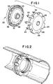
- this stapler 10 is capable of holding the fasteners or plates 20, 30 as indicated in Figure 1.
- these fasteners 20, 30 are generally absorbable and formed from known biocompatible materials. Of course, it is to be realized that the material may also be metallic without departing from this invention.
- These fasteners 20, 30 replace a standard anastomotic staple line.
- Each of these fasteners is plate shaped and at least one such fastener contains a central toric section 22, 32 to be removed from the plates 20, 30. This toric section allows the pull-through function of the fastener system.
- one of the fasteners 20 has prongs 24 which are sharpened so as to pierce tissue.
- the other fastener 30 has multiple receivers 34 which number more than the prongs 24 on plate 20. This arrangement allows each of the prongs 24 to have little or no difficulty in alignment within the receivers 34 on the other fastener 30. Nonetheless, each plate 20, 30 generally has at least eight such prongs and receivers 24, 34.
- the alignment aspect is very important concerning these fasteners 20, 30. It is to be realized that with conventional staples, and conventional staplers, the staples are pre-aligned with anvils so that the staples . are readily formed after piercing through tissue. In contrast, it is necessary to have these fasteners 20, 30 self-aligning so that the fasteners themselves meet with one another. Thus, the prongs 24 are configured so that they will readily be urged into each of the receiving receivers 34. For instance, as seen in Figures 11 and 12, there are displayed twice as many prongs 24 as there are receivers 34, so that alignment requires very little rotation of fastener 20.
- the receivers 34 are equal or greater in number to the prongs 24 and are wide enough so that the prongs 24 will fit within each of the receivers 34. Also, either fastener is capable of rotating slightly within the head or anvil portion in which it is held so that this alignment may take place. This will become more readily understandable when the stapler 10 is further explained in a later portion of this specification.
- the plates 20, 30 are formed to be generally thin (about .010 ⁇ to .030 ⁇ thick) so that they do not take up much space within the housing of an instrument or between tissue; as well, with thinner plates 20, 30 the force required to fire a plate 20, 30 is reduced, resulting in easier surgeon use. Naturally, such reduced thickness is configured so as to not inhibit holding strength of the fasteners 20, 30.
- each plate 20, 30 has a frangible ring 26, 36 within the circumference of the plate.
- These rings 26, 36 are intended to be broken by the force of a knife 40 (best seen in Figure 6) so that fasteners 20, 30 are broken and the frangible rings 26, 36 of each of the plates 20, 30 is pulled within the head 50 of instrument 10.
- Stapler 10 is then removed from the cutting-site, leaving the outer portions 23, 38 of plates 20, 30 locked and connected with connected tissue placed between.
- the fasteners 20, 30 have been formed either without a center or with separable rings 26, 36 center so that the rings 26, 36 as well as the cut tissue is gathered within the head 50 of the instrument 10. This allows the pulling through of the anvil 60 of the instrument 40, as is best seen in Figure 9. Previously, it would be necessary to detach the anvil 60 from the staple before pulling the instrument through the connected tissue. This capability of not "unbuttoning" the anvil 60 from the stapler 10 results in a vast improvement compared to some previous circular anastomotic staplers.
- Stapler 10 is a stapler with a generally circular cross-section of the the type normally used for anastomosis. However, as better seen in Figures 6, 7, 8 and 9, this stapler 10 contains a pair of plates 20, 30 seated within the stapling area. One plate 20, 30 is placed within the anvil section 60 and one within the head or driving section 50. The instrument 10 itself performs the anastomosis by attaching plates 20, 30 rather than conventional staples.
- tissue held around the head 50 is approximated to tissue held on the anvil 60 so that the tissue is ready for anastomosis.
- the prongs 24 of one of the fasteners 20 pierce both layers of tissue and lock within the receivers 34 of the other fastener 30.
- a knife 40 in the instrument is pushed forward by further compression of the handle mechanism 100.
- First one plate 20 is cut, then tissue (both layers), then the last plate 30.
- tissue both layers
- the last plate 30 is formed as held within the anvil 60.
- the fasteners 20, 30 remaining as the outer portions 28, 38 are locked together with tissue held between.
- the instrument 10 is able to be removed by pulling it through the tissue that has been cut and away from the area which has been anastomosed.
- the instrument may take on a number of different configurations.
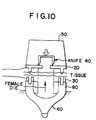
- the mechanism may be formed with a male die 70 held within the anvil 60 of the instrument 10. In this manner the anvil 60 will be pulled into the instrument.
- the handle 100 causes reversal of motion in the direction of the arrow, so that the anvil 60 is pulled toward the handle. This creates a force from anvil 60 on plate 20.
- the plate 20 receives the force exerted against it and the inner frangible ring 26 of the plate 22 breaks at the frangible ring 26, leaving the outer portion 28.
- timing spring 57 has adequate force to cause the tissue to be pierced by prongs 24 and the receivers 34 to be locked onto plate 20, so that the tissue is adequately held between both plates 20, 30.
- timing spring 57 is therefore capable of providing a constant closure pressure throughout the closure and cutting of the tissue. This enables the designer to easily adapt stapler 10 to create enough mechanical advantage so that closure and latching as well as cutting can be accomplished in a single stroke of the mechanism. Or, it may be desirable to first pierce the tissue and latch with one stroke of the mechanism. Then, it may be further desirable to complete closure and cut the tissue with a second stroke. This may result in further reliability and ease of firing of the mechanism.
- the force from the anvil 60 then overcomes the tissue as well as plates 20, 30 and spring 57 force so that the plate 30 abuts knife 40.
- knife 40 cuts through the frangible ring 36, then the two layers of tissue.
- Frangible ring 26 of plate 20 is then either cut by the knife 40, or broken by the anvil 60, depending upon design specifications.
- tissue is then locked within the upper receiving plate 30 which contains receivers 34 and a female die 80.
- knife 40 is advanced further so that it breaks first the pronged plate 20 at frangible ring 28, then the two layers of tissue, then the lower plate 30 at frangible ring 36.
- the entire cut portion of tissue is held within the anvil 60.
- Anvil is then removed back through the head portion 50 so that properly anastomosed tissued is revealed.
- the configuration of the plates may be slightly different. For instance, it may be desired to reduce the force necessary to cut through the tissue by removing one of the inner portions 22, 32 of the two plates beforehand. In this way, closure takes place on the outer rings 22, 32 and the knife mechanism 40 abuts only tissue. It can further be envisioned to use a ring-type mechanism where the inner portions 28, 38 of plates 20, 30 do not even exist and only prongs 24 and receivers 34 create closure. Of course knife action should then take place using alternate methods. In this manner, it is possible to reduce force to fire the instrument 10, while maintaining the proper orientation of the rings containing components 24, 34. The only certain requirements, therefore, in any of these embodiments are alignment of the fasteners, the creation of enough force to hold the plates 20, 30, and proper cutting by knife 40 in preparing the anastomosis.
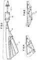
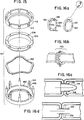
- FIG. 15 An alternate embodiment to the combination as seen in Figs. 1 and 2 is shown in Figure 15, wherein there is described ring combination 110 which comprises a receiver 112, a pressure plate 122, an optional wave spring 132, and a piercer ring 142.
- the piercer ring contains flanges 144 which are placed at the edge of a plurality of legs 146. These flanges are ultimately engaged with the latches 114 contained on receiver 112.
- Pressure plate 122 is provided so that there is placed a spring force on flanges 144.
- wave spring 132 may be placed between receiver 112 and piercer ring 142. This places a similar spring force to that of pressure plate 122.
- wave spring 132 and pressure plate 122 can be used together.
- FIG. 15 allows the user to pierce and grip tissue with the piercer ring 142 holding receiver 112 in place with tissue held therebetween.
- stapler 10 is able to be removed through the center of receiver 112 and piercer ring 142.
- this improved ring combination 110 allows accurate and easy placement of anastomosed tissue.
- Ring combination 110 is made in 21, 25, 29 and 33 mm diameters. These allow for accurate placement for anastomosis and easy removal of the stapling device through the anal canal.
- the materials used are initially hard and then terminally soft absorbable polymers, such that their consistency at the time of their expulsion is soft and pliable. These permit usage of such anastomotic rings in other sites, where absorption rather than expulsion is the procedure the body uses to remove these rings.
- FIGs. 16a, 16b, 16c and 16d A second alternate combination is seen is Figs. 16a, 16b, 16c and 16d.
- ring combination 150 comprises receiver 152 and piercer ring 162.
- Piercer ring 162 contains legs 166 having ratchet flanges 164 at their ends.
- Receiver 152 contains receiving holes 154. The usefulness of the combination of receiver 152 and piercer ring 162 will be apparent.
- the ring 162 which is generally made up of absorbable materials, is designed with multiple flanges spaced apart to allow an adjustment of closure height.
- the ratchet locking closure mechanism as seen in flanges 164 causes less tissue damage by maintaining tissue therein, but not holding it together so tightly that it is traumatized.
- ratchet flanges 165 which may be placed on legs 166, such that a number of useful gap setting distances are provided.
- ratchet flanges 164 as seen in Fig. 16a, where there are only three such flanges, here the user is able to choose over a relatively infinite range, the appropriate spacing between the two rings containing receiver 152 and piercer ring 162.
- a sliding flange 174 which allows for placement into the piercer ring 162.
- Gripper prongs 175 on the receiving holes 154 enable the accurate setting of the rings 152, 162 in place, through the use of compression. In this way, the pressure placed by flanges 174 on prongs 175 hold the relative position of the rings 152, 162.
Abstract
Description
- Generally, this invention relates to an apparatus for circular surgical stapling. More specifically, this invention relates to anastomotic fastening using absorbable staples. Most specifically, this invention relates to circular anastomotic fastening using absorbable staples, and the means to apply such staples.
- Currently, there exist a number of surgical anastomotic circular staplers. Generally, these staplers are used to connect severed lumen with a circular ring of staples displayed around a circumference to connect the tissue. In most instances, a knife mechanism is used to cut the tissue within the circumference of the staple ring. The ring of staples is generally a number of small metallic surgical staples, usually between 20 and 40 staples, which form a ring roughly 2 cm to 4 cm in diameter. Naturally, with the circular staples there must be minimum constriction of the tissue after healing, and the lumen must be maintained as near as possible as prior to the procedure, to allow normal passage of fluids.
- With this type of stapler, there must be a complete 360° seal of tissue so that no gaps exist between the connected tissue. In addition, it is naturally desirable that when the tissue is connected, the volume within which the tissue is cut be maintained so that the tissue is continually able to pass fluids without encountering constricting tissue.
- In addition, with such circular anastomotic staplers it is desirable to make staplers which are disposable. That is, disposable staplers are now well accepted by surgeons. Disposable surgical staplers also help prevent the spreading of bacteria or germs. Naturally, the surgeon also desires a manual stapler which gives good off-the-shelf reliability and allows a controlled one-handed operation.
- Most importantly, there has been a need for absorbable staplers in the circular fastening market. This is due in part to the prior incapacity to produce a circular anastomotic stapling mechanism where the staples are able to be received within receivers and adequate forces can be generated to hold the tissue together and to clamp the staples. In addition, it is critical in this system to maintain tolerances which enable alignment of staples or fasteners within the receivers. To accomplish this in an absorbable circular anastomotic stapler would increase the likelihood of use of such a stapler within hard to reach or marginally compliant lumen. It is to be realized that typical absorbable fasteners have an enlarged size, preventing use in such places.
- Furthermore, it is desirable to replace a standard staple line with two adaptively connectable fasteners. In this way, the need for bending of staples is removed, and yet closure and hemostasis are possible. Of course, by attempting to formulate a system in which a standard staple line is replaced, it would be desirable to formulate such a stapler so that the stapler itself can be pulled through the attached part of the tissue without the need for removing the anvil portion of the stapler. This results in a rapid and efficient method of removing the stapler. In the desire for creating such a adaptively connectable mating fastener, it is naturally desirable that these fasteners are both positively aligned and latching, and that they are formulated so that the instrument creates closure at some constantly adjustable closure pressure. If the pressure required to attach the latching members together remains constant, it is much easier to close and latch the instrument with a smooth, efficient single stroke. Alternately, it may be desirable to rely on the constant closure pressure to attach the fastener through the tissue, and then, in a separate action, actually close the tissue with the instrument.
- In such a system it would also be desirable to readily see whether the fasteners are connected and the tissue is adequately closed. This is especially true where the instrument is pulled through the connected tissue. Also, these type connections should be available on all circular-type instruments, including those with curved shafts or instruments containing trocars or flexible shafts.
- It is therefore an object of this invention to provide a circular anastomotic stapler which provides good alignment between staples and receivers. It is further an object of the invention to provide an absorbable circular anastomotic stapler which provides such alignment.
- It is yet another object of the invention to provide a means which apply such absorbable staples, and yet maintain alignment between staple and receiver.
- It is further desirable to create a surgical anastomotic stapler which accomplishes these criteria while allowing the user to cut and remove inner portions of tissue and or staple which constrict the volume of fluid which passes through the connected lumen.
- It is again desirable to provide such a circular anastomotic stapler wherein the standard staple line are replaced by two separably connectable fastening parts.
- It may yet be more desirable that the separatly connectable parts have a separable center which will result in the pulling through of the device after the fasteners are connected.
- While it may desirable in some instances to form the fasteners of the invention from absorbable means, it is again more desirable that the mechanism formed has fasteners which are both latching and self-aligning.
- It is further desirable that the closure is affected either with a single or double stroke, but at some predetermined closure dimension.
- It is further desirable that the instrument be capable of providing quick, ready, and accurate user feedback in that the remaining fastened tissue is easily inspectable for closure and hemostasis while the remainder of the instrument can be removed rapidly from the site.
- It is yet again desirable to be able to perform such a stapling operation with a stapler that may be pulled through the resulting anastomosed tissue.
- It is finally desirable that such an instrument be capable of being used with either a straight or curved shaft instrument, with or without a trocar attached to the head portion of the shaft.
- These and other objects of the invention are accomplished in a mechanism arranged to anastomose two lumens with an absorbable fastener. The fastener is created from two washer-like pieces. One of the washer-like pieces has holes which are adaptable to receive latching prongs protruding from the other such washer-like piece. Fastening is accomplished through a singluar linear motion in which the prongs pierce the tissue, then latch within the holes in the receiver. Finally, the tissue is cut by a circular knife which also creates a final ring-like shape of the fastener within the tissue. The inner portion of each of the washer-like pieces is removed along with the cut tissue when the instrument is removed from the lumen.
- The knife is able to shear the tissue against a die when the knife overcomes a spring force after latching and causes the knife to cut both tissue and the inner portion of each of the washer-like pieces. Overstroke of the die or the knife causes releasing closure from the distal end of the instruments so that removal is easy. One such mechanism is able to reverse the position of receivers and flanges so that the fastener prongs can be oriented in any direction before use.
- The invention will be better understood by the attached drawings in which:
- Fig. 1 and Fig. 11 are perspective views of a fastener and receiver of the invention, of which Fig. 12 is a perspective view partially cut-away;
- Fig. 2 is a perspective view of the components of Fig. 1 joined inside lumen;
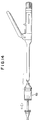
- Fig. 3 is a side elevation of a means for applying the fasteners in Fig. 1.;
- Figs. 4 and 5 demonstrate a handle mechanism of the means of Fig. 3;
- Figures 10, 13 and 14 are is an alternate embodiments of the means of Fig. 3, in cross-section;
- Figs. 6, 7, 8 and 9 are particularized cross-sectional views of the application of the means in Fig. 1 as used in the apparatus of Fig. 3; and
- Figs. 15, 16a, 16b, 16c, and 16d are views of alternate embodiment fastener arrangements to those shown in Fig. 1.
- As seen in Figures 1 through 12, there is disclosed a surgical stapling device which is capable of performing surgical anastomotic circular stapling. As seen in Figure 3, this
stapler 10 is capable of holding the fasteners orplates - As seen in Figures 1 and 2, 11 and 12 these
fasteners fasteners toric section plates fasteners 20 hasprongs 24 which are sharpened so as to pierce tissue. Theother fastener 30 hasmultiple receivers 34 which number more than theprongs 24 onplate 20. This arrangement allows each of theprongs 24 to have little or no difficulty in alignment within thereceivers 34 on theother fastener 30. Nonetheless, eachplate receivers - The alignment aspect is very important concerning these
fasteners fasteners prongs 24 are configured so that they will readily be urged into each of the receivingreceivers 34. For instance, as seen in Figures 11 and 12, there are displayed twice asmany prongs 24 as there arereceivers 34, so that alignment requires very little rotation offastener 20. Thereceivers 34 are equal or greater in number to theprongs 24 and are wide enough so that theprongs 24 will fit within each of thereceivers 34. Also, either fastener is capable of rotating slightly within the head or anvil portion in which it is held so that this alignment may take place. This will become more readily understandable when thestapler 10 is further explained in a later portion of this specification. - The
plates thinner plates plate fasteners - It will be noticed from the Figures 1 and 2 that each
plate frangible ring fasteners frangible rings plates head 50 ofinstrument 10.Stapler 10 is then removed from the cutting-site, leaving theouter portions 23, 38 ofplates - The
fasteners separable rings rings head 50 of theinstrument 10. This allows the pulling through of theanvil 60 of theinstrument 40, as is best seen in Figure 9. Previously, it would be necessary to detach theanvil 60 from the staple before pulling the instrument through the connected tissue. This capability of not "unbuttoning" theanvil 60 from thestapler 10 results in a vast improvement compared to some previous circular anastomotic staplers. - The
instrument 10 in which theseplates Stapler 10 is a stapler with a generally circular cross-section of the the type normally used for anastomosis. However, as better seen in Figures 6, 7, 8 and 9, thisstapler 10 contains a pair ofplates plate anvil section 60 and one within the head or drivingsection 50. Theinstrument 10 itself performs the anastomosis by attachingplates - As better seen in the operational breakdown in Figures 6, 7, 8 and 9, first, tissue held around the
head 50 is approximated to tissue held on theanvil 60 so that the tissue is ready for anastomosis. Next, theprongs 24 of one of thefasteners 20 pierce both layers of tissue and lock within thereceivers 34 of theother fastener 30. - After locking, a
knife 40 in the instrument is pushed forward by further compression of the handle mechanism 100. First oneplate 20 is cut, then tissue (both layers), then thelast plate 30. Thus, as in Fig. 9, as held within theanvil 60, there is formed a package containing inner brokenfrangible rings toric sections fasteners outer portions instrument 10 is able to be removed by pulling it through the tissue that has been cut and away from the area which has been anastomosed. - As better seen in Figures 4, 5, 6 and 10, the instrument may take on a number of different configurations. First, as better seen in Figure 6, the mechanism may be formed with a
male die 70 held within theanvil 60 of theinstrument 10. In this manner theanvil 60 will be pulled into the instrument. As seen in the mechanism of Figures 4 and 5, the handle 100 causes reversal of motion in the direction of the arrow, so that theanvil 60 is pulled toward the handle. This creates a force fromanvil 60 onplate 20. Theplate 20 receives the force exerted against it and the innerfrangible ring 26 of theplate 22 breaks at thefrangible ring 26, leaving theouter portion 28. - This is accomplished, of course, after the
prongs 24 of theplate 20 have pierced tissue and been received within thereceivers 34 end of theplate 30, enclosed within thefastening block 55 on thehead 50 of theinstrument 10. Thefastening block 55 is held forward by atiming spring 57. Thistiming spring 57 has adequate force to cause the tissue to be pierced byprongs 24 and thereceivers 34 to be locked ontoplate 20, so that the tissue is adequately held between bothplates - It is to be noted that timing
spring 57 is therefore capable of providing a constant closure pressure throughout the closure and cutting of the tissue. This enables the designer to easily adaptstapler 10 to create enough mechanical advantage so that closure and latching as well as cutting can be accomplished in a single stroke of the mechanism. Or, it may be desirable to first pierce the tissue and latch with one stroke of the mechanism. Then, it may be further desirable to complete closure and cut the tissue with a second stroke. This may result in further reliability and ease of firing of the mechanism. - The force from the
anvil 60 then overcomes the tissue as well asplates spring 57 force so that theplate 30 abutsknife 40. First,knife 40 cuts through thefrangible ring 36, then the two layers of tissue.Frangible ring 26 ofplate 20 is then either cut by theknife 40, or broken by theanvil 60, depending upon design specifications. - What remains therefore is for the
entire anvil 60 with tissue andplates knife 40 so that a volume is held within thehandle head 50. This is then pulled away from the connected tissue. Thus, the remainingouter portions - On the other hand, as seen in Figure 10, there is also possible the reversal of the
plates pronged plate 20 is on thehead portion 50 of theinstrument 10. In this way, force is created in the direction of the arrow by theknife 40 to push against theplate 20.Plate 20 then pierces both layers of tissue. - The tissue is then locked within the upper receiving
plate 30 which containsreceivers 34 and afemale die 80. After locking,knife 40 is advanced further so that it breaks first thepronged plate 20 atfrangible ring 28, then the two layers of tissue, then thelower plate 30 atfrangible ring 36. Thus, the entire cut portion of tissue is held within theanvil 60. Anvil is then removed back through thehead portion 50 so that properly anastomosed tissued is revealed. - Further examining the mechanism as in Figures 3, 4 and 5, it is to be noted that the combination mechanical elements comprising links 115 and slide 120 causes the handle 100 to move forward the
knife 40 contained inhead 50 of theinstrument 10. If one additional link 115 is added, it will be appreciated that the position and motion ofknife 40 may be reversed so that theknife 40 retracts into thestapler 110. In this way, it is possible to perform anastomosis with whichever is the desired configuration of the twoplates - Of course, it should be noted that the configuration of the plates may be slightly different. For instance, it may be desired to reduce the force necessary to cut through the tissue by removing one of the
inner portions knife mechanism 40 abuts only tissue. It can further be envisioned to use a ring-type mechanism where theinner portions plates receivers 34 create closure. Of course knife action should then take place using alternate methods. In this manner, it is possible to reduce force to fire theinstrument 10, while maintaining the proper orientation of therings containing components plates knife 40 in preparing the anastomosis. - Thus, after the
stapler 10 withanvil 60 attached, and cut tissue between, has been pulled through the closed tissue, this results in more accurate and positive user feedback. The user is able to inspect the "donut" of tissue and fastener remaining in thestapler 10. Also, because the instrument has been pulled through the closed tissue, the user is able to inspect the portion of tissue which remains without the instrument obscuring the results obtained by closure. This creates a more reliable and accurate closure system. - Alternately, of course, there is possible the incorporation of the stapling configuration of the present invention in current stapling. As seen in Figures 13 and 14, currently produced staplers 100, 200 may be incorporated with the
head 50 of this invention, and also may be provided withfasteners - An alternate embodiment to the combination as seen in Figs. 1 and 2 is shown in Figure 15, wherein there is described
ring combination 110 which comprises areceiver 112, apressure plate 122, anoptional wave spring 132, and apiercer ring 142. The piercer ring containsflanges 144 which are placed at the edge of a plurality oflegs 146. These flanges are ultimately engaged with thelatches 114 contained onreceiver 112.Pressure plate 122 is provided so that there is placed a spring force onflanges 144. Optionally,wave spring 132 may be placed betweenreceiver 112 andpiercer ring 142. This places a similar spring force to that ofpressure plate 122. Of course,wave spring 132 andpressure plate 122 can be used together. - The system disclosed in Figure 15 allows the user to pierce and grip tissue with the
piercer ring 142 holdingreceiver 112 in place with tissue held therebetween. Of course, with theanvil section 60 and the head or drivingsection 50 conforming to those previously described in the stapler embodiments,stapler 10 is able to be removed through the center ofreceiver 112 andpiercer ring 142. Thus, this improvedring combination 110 allows accurate and easy placement of anastomosed tissue. -
Ring combination 110 is made in 21, 25, 29 and 33 mm diameters. These allow for accurate placement for anastomosis and easy removal of the stapling device through the anal canal. The materials used are initially hard and then terminally soft absorbable polymers, such that their consistency at the time of their expulsion is soft and pliable. These permit usage of such anastomotic rings in other sites, where absorption rather than expulsion is the procedure the body uses to remove these rings. - A second alternate combination is seen is Figs. 16a, 16b, 16c and 16d. As seen in Fig. 16a and 16b there is disclosed
ring combination 150, and comprisesreceiver 152 andpiercer ring 162.Piercer ring 162 containslegs 166 havingratchet flanges 164 at their ends.Receiver 152 contains receivingholes 154. The usefulness of the combination ofreceiver 152 andpiercer ring 162 will be apparent. In and end-to-end anastomosis, thering 162 which is generally made up of absorbable materials, is designed with multiple flanges spaced apart to allow an adjustment of closure height. The ratchet locking closure mechanism as seen inflanges 164 causes less tissue damage by maintaining tissue therein, but not holding it together so tightly that it is traumatized. - As seen in Figs. 16c and 16d, there are shown two alternate embodiments of the ratcheting mechanism as contained in Figs. 16a and 16b. In Fig. 16d there is shown
ratchet flanges 165 which may be placed onlegs 166, such that a number of useful gap setting distances are provided. In contrast to ratchetflanges 164 as seen in Fig. 16a, where there are only three such flanges, here the user is able to choose over a relatively infinite range, the appropriate spacing between the tworings containing receiver 152 andpiercer ring 162. On the other hand, as in Fig. 16c, there is disclosed a slidingflange 174 which allows for placement into thepiercer ring 162. Gripper prongs 175 on the receivingholes 154 enable the accurate setting of therings flanges 174 onprongs 175 hold the relative position of therings - These and other embodiments of the invention have been described as above. Of course, it may be possible to vary the stapler and fastener of the present invention without deviating from the intent of this invention. For instance, it is possible to create an apparatus with a curved longitudinal shaft, or having a flexible shaft, or where the shaft portion near the distal end contains a trocar instrument. What is to be realized is that it is the following claims and their equivalents which are meant to cover the scope of the invention.
Claims (10)
- A compression anastomosis device comprising:
a piercing ring containing a plurality of piercing flanges;
a receiving ring containing a plurality of receiving slots corresponding to said flanges; and
spring means for emplacement between said piercing and receiving rings. - The device of Claim 1 wherein said spring means is a wave spring.
- The device of Claim 1 where said spring means is a pressure plate formed to fit within said piercing ring and containing a plurality of fingers corresponding to said flanges and wherein said fingers exert a spring force on said flanges.
- The device of Claim 3 wherein a wave spring fits between said piercing ring and said pressure plate.
- The device of Claim 3 or Claim 4 wherein said piercing ring contains an outer wall and a ledge built into said outer wall such that said pressure plate fits on said ledge.
- A compression anastomosis device comprising:
a piercing ring containing a plurality of piercing flanges;
a receiving ring containing a plurality of receiving slots corresponding to said flanges; and
ratchet means located on said flanges. - The device of Claim 6 and any one of Claims 1-5 further including spring means for emplacement between said piercing and receiving rings.
- The device of any preceding Claim wherein all of said components are formed from biodegradable polymers.
- The device of Claim 6 or Claim 7 wherein said ratchet means includes a sliding portion on the end of said flanges and a locking means on said flange adjacent said sliding means.
- The device of Claim 6 or Claim 7 wherein said ratchet means comprises closely spaced together detents such that said flange is adjustable on said receiving ring.
Applications Claiming Priority (2)
| Application Number | Priority Date | Filing Date | Title |
|---|---|---|---|
| US709860 | 1991-06-03 | ||
| US07/709,860 US5250058A (en) | 1991-01-17 | 1991-06-03 | Absorbable anastomosic fastener means |
Publications (2)
| Publication Number | Publication Date |
|---|---|
| EP0517488A1 true EP0517488A1 (en) | 1992-12-09 |
| EP0517488B1 EP0517488B1 (en) | 1996-04-24 |
Family
ID=24851575
Family Applications (1)
| Application Number | Title | Priority Date | Filing Date |
|---|---|---|---|
| EP92305058A Expired - Lifetime EP0517488B1 (en) | 1991-06-03 | 1992-06-02 | Absorbable anastomosic fastener means |
Country Status (9)
| Country | Link |
|---|---|
| EP (1) | EP0517488B1 (en) |
| JP (1) | JPH06165786A (en) |
| AT (1) | ATE137097T1 (en) |
| AU (1) | AU651691B2 (en) |
| BR (1) | BR9202110A (en) |
| CA (1) | CA2070005A1 (en) |
| DE (1) | DE69210100T2 (en) |
| ES (1) | ES2086656T3 (en) |
| GR (1) | GR1002290B (en) |
Cited By (21)
| Publication number | Priority date | Publication date | Assignee | Title |
|---|---|---|---|---|
| DE4417528A1 (en) * | 1993-05-21 | 1994-12-22 | Biovision Gmbh | Anastomosis device |
| US5376098A (en) * | 1992-10-09 | 1994-12-27 | United States Surgical Corporation | Fragmentable anastomosis ring applier |
| US5454824A (en) * | 1992-10-09 | 1995-10-03 | United States Surgical Corporation | Fragmentable ring applier |
| US5503635A (en) * | 1993-11-12 | 1996-04-02 | United States Surgical Corporation | Apparatus and method for performing compressional anastomoses |
| US5562690A (en) * | 1993-11-12 | 1996-10-08 | United States Surgical Corporation | Apparatus and method for performing compressional anastomoses |
| US6149667A (en) * | 1998-05-11 | 2000-11-21 | Surgical Connections, Inc. | Devices and methods for treating E.G. urinary stress incontinence |
| US6517566B1 (en) | 1998-05-11 | 2003-02-11 | Surgical Connections, Inc. | Devices and methods for treating e.g. urinary stress incontinence |
| EP1341446A1 (en) * | 2000-09-01 | 2003-09-10 | Angiolink Corporation | Wound site management and wound closure device |
| US6740098B2 (en) | 1998-05-11 | 2004-05-25 | Surgical Connections, Inc. | Surgical stabilizer devices and methods |
| WO2005030096A1 (en) * | 2003-09-22 | 2005-04-07 | Dvl Acquisition Sub, Inc. | Connector assembly for joining a graft vessel to a side of a target vessel |
| EP1875870A1 (en) * | 2006-07-07 | 2008-01-09 | Ethicon Endo-Surgery, Inc. | A surgical stapling instrument. |
| EP1908418A1 (en) * | 2006-10-06 | 2008-04-09 | Ethicon Endo-Surgery, Inc. | An anastomotic applier |
| EP1908419A1 (en) * | 2006-10-06 | 2008-04-09 | Ethicon Endo-Surgery, Inc. | A locking device for an anastomotic device |
| EP1908421A1 (en) * | 2006-10-06 | 2008-04-09 | Ethicon Endo-Surgery, Inc. | A carrier member, anastomotic device and instrumentation for performing endoluminal and/or transluminal anastomosis |
| EP2151199A1 (en) * | 2008-08-05 | 2010-02-10 | Tyco Healthcare Group, LP | Magnetic compression anastomosis device |
| CN101522110B (en) * | 2006-10-06 | 2012-03-21 | 伊西康内外科公司 | Anastomotic ring device with locking means |
| WO2014046596A1 (en) * | 2012-09-20 | 2014-03-27 | Carponovum Ab | A mounting tool for an anastomotic device |
| US9402605B2 (en) | 2009-04-16 | 2016-08-02 | Covidien Lp | Magnetically retained incision closure devices and methods of incision closure using same |
| CN107432758A (en) * | 2017-09-14 | 2017-12-05 | 史源 | A kind of support bar and stapling apparatus of double thread structure |
| CN108095789A (en) * | 2018-02-05 | 2018-06-01 | 赵舒 | A kind of degradable anastomotic component and the stapler with the degradable anastomotic component |
| CN108882939A (en) * | 2016-04-01 | 2018-11-23 | 伊西康公司 | Supporter and dispositions method are reinforced in the suture that coincide |
Families Citing this family (8)
| Publication number | Priority date | Publication date | Assignee | Title |
|---|---|---|---|---|
| US6769594B2 (en) * | 2002-05-31 | 2004-08-03 | Tyco Healthcare Group, Lp | End-to-end anastomosis instrument and method for performing same |
| ES2383252T3 (en) * | 2002-06-17 | 2012-06-19 | Tyco Healthcare Group Lp | Annular Support Structures |
| CN1317999C (en) * | 2005-08-03 | 2007-05-30 | 刘罕宇 | Anastomat of circular closing organ for operation |
| ITMI20060062A1 (en) * | 2006-01-16 | 2007-07-17 | Ethicon Endo Surgery Inc | ANASTOMOTIC DEVICE SUITABLE FOR CLOSING AND PREVIOUSLY KEEPING A FIRST PORTION OF FABRIC AND A SECOND PORTION OF FABRICS FOR THE FORMATION OF ANASTICOSUS |
| ITMI20060060A1 (en) * | 2006-01-16 | 2007-07-17 | Ethicon Endo Surgery Inc | PR POSITIONING DEVICE DEPLOY AT LEAST ONE BLOCKING PORTION OF AN ANASTOMOTIC DEVICE AND THE PEER METHOD PERFORM ANASTOMOSIS IN THE DIGESTIVE TUBE |
| JP5037534B2 (en) * | 2006-02-15 | 2012-09-26 | エシコン・エンド−サージェリィ・インコーポレイテッド | Device, clip, endoscope, and method for intracavitary treatment of tissues such as hemorrhoids |
| DE102008055587B4 (en) * | 2008-02-14 | 2017-04-06 | Adolf Picek | Plug prosthesis in a variety of needs for rapid Anastomosis of blood vessels and other relatively soft tubular organs |
| US8430292B2 (en) | 2009-10-28 | 2013-04-30 | Covidien Lp | Surgical fastening apparatus |
Citations (4)
| Publication number | Priority date | Publication date | Assignee | Title |
|---|---|---|---|---|
| US4523592A (en) * | 1983-04-25 | 1985-06-18 | Rollin K. Daniel P.S.C. | Anastomotic coupling means capable of end-to-end and end-to-side anastomosis |
| US4752024A (en) * | 1986-10-17 | 1988-06-21 | Green David T | Surgical fastener and surgical stapling apparatus |
| EP0282157A1 (en) * | 1987-02-11 | 1988-09-14 | AVANT, Odis Lynn | Stapling apparatus for anastomosis, in particular for urethra-bladder anastomosis |
| FR2612392A1 (en) * | 1987-03-19 | 1988-09-23 | Audion Michel | Interrupted biodegradable composites of variable strength |
Family Cites Families (2)
| Publication number | Priority date | Publication date | Assignee | Title |
|---|---|---|---|---|
| US4294255A (en) * | 1978-04-17 | 1981-10-13 | Andre Geroc | Intraluminal anastomosis |
| US4917114A (en) * | 1986-10-17 | 1990-04-17 | United States Surgical Corporation | Surgical fastener and surgical stapling apparatus |
-
1992
- 1992-03-18 GR GR920100109A patent/GR1002290B/en not_active IP Right Cessation
- 1992-05-07 JP JP4141051A patent/JPH06165786A/en active Pending
- 1992-05-20 AU AU17022/92A patent/AU651691B2/en not_active Expired
- 1992-06-01 CA CA002070005A patent/CA2070005A1/en not_active Abandoned
- 1992-06-02 EP EP92305058A patent/EP0517488B1/en not_active Expired - Lifetime
- 1992-06-02 DE DE69210100T patent/DE69210100T2/en not_active Expired - Lifetime
- 1992-06-02 ES ES92305058T patent/ES2086656T3/en not_active Expired - Lifetime
- 1992-06-02 BR BR929202110A patent/BR9202110A/en not_active Application Discontinuation
- 1992-06-02 AT AT92305058T patent/ATE137097T1/en not_active IP Right Cessation
Patent Citations (4)
| Publication number | Priority date | Publication date | Assignee | Title |
|---|---|---|---|---|
| US4523592A (en) * | 1983-04-25 | 1985-06-18 | Rollin K. Daniel P.S.C. | Anastomotic coupling means capable of end-to-end and end-to-side anastomosis |
| US4752024A (en) * | 1986-10-17 | 1988-06-21 | Green David T | Surgical fastener and surgical stapling apparatus |
| EP0282157A1 (en) * | 1987-02-11 | 1988-09-14 | AVANT, Odis Lynn | Stapling apparatus for anastomosis, in particular for urethra-bladder anastomosis |
| FR2612392A1 (en) * | 1987-03-19 | 1988-09-23 | Audion Michel | Interrupted biodegradable composites of variable strength |
Cited By (40)
| Publication number | Priority date | Publication date | Assignee | Title |
|---|---|---|---|---|
| US5376098A (en) * | 1992-10-09 | 1994-12-27 | United States Surgical Corporation | Fragmentable anastomosis ring applier |
| US5454824A (en) * | 1992-10-09 | 1995-10-03 | United States Surgical Corporation | Fragmentable ring applier |
| DE4417528A1 (en) * | 1993-05-21 | 1994-12-22 | Biovision Gmbh | Anastomosis device |
| US5503635A (en) * | 1993-11-12 | 1996-04-02 | United States Surgical Corporation | Apparatus and method for performing compressional anastomoses |
| US5562690A (en) * | 1993-11-12 | 1996-10-08 | United States Surgical Corporation | Apparatus and method for performing compressional anastomoses |
| US5697943A (en) * | 1993-11-12 | 1997-12-16 | United States Surgical Corporation | Apparatus and method for performing compressional anastomoses |
| US6517566B1 (en) | 1998-05-11 | 2003-02-11 | Surgical Connections, Inc. | Devices and methods for treating e.g. urinary stress incontinence |
| WO1999058081A3 (en) * | 1998-05-11 | 2000-11-23 | Claire T Hovland | Devices and methods for treating e.g. urinary stress incontinence |
| US6149667A (en) * | 1998-05-11 | 2000-11-21 | Surgical Connections, Inc. | Devices and methods for treating E.G. urinary stress incontinence |
| US6740098B2 (en) | 1998-05-11 | 2004-05-25 | Surgical Connections, Inc. | Surgical stabilizer devices and methods |
| EP1341446A1 (en) * | 2000-09-01 | 2003-09-10 | Angiolink Corporation | Wound site management and wound closure device |
| EP1341446A4 (en) * | 2000-09-01 | 2007-06-20 | Angiolink Corp | Wound site management and wound closure device |
| WO2005030096A1 (en) * | 2003-09-22 | 2005-04-07 | Dvl Acquisition Sub, Inc. | Connector assembly for joining a graft vessel to a side of a target vessel |
| EP1875870A1 (en) * | 2006-07-07 | 2008-01-09 | Ethicon Endo-Surgery, Inc. | A surgical stapling instrument. |
| WO2008003582A2 (en) * | 2006-07-07 | 2008-01-10 | Ethicon Endo-Surgery, Inc. | A surgical stapling instrument |
| WO2008003582A3 (en) * | 2006-07-07 | 2008-05-02 | Ethicon Endo Surgery Inc | A surgical stapling instrument |
| WO2008040573A1 (en) * | 2006-10-06 | 2008-04-10 | Ethicon Endo-Surgery, Inc. | A carrier member, anastomotic device and instrumentation for performing endoluminal and/or transluminal anastomosis |
| CN101522110B (en) * | 2006-10-06 | 2012-03-21 | 伊西康内外科公司 | Anastomotic ring device with locking means |
| WO2008040580A1 (en) * | 2006-10-06 | 2008-04-10 | Ethicon Endo-Surgery, Inc. | An anastomotic applier |
| WO2008040577A1 (en) * | 2006-10-06 | 2008-04-10 | Ethicon Endo-Surgery, Inc. | A locking device for an anastomotic device |
| EP1908419A1 (en) * | 2006-10-06 | 2008-04-09 | Ethicon Endo-Surgery, Inc. | A locking device for an anastomotic device |
| EP1908418A1 (en) * | 2006-10-06 | 2008-04-09 | Ethicon Endo-Surgery, Inc. | An anastomotic applier |
| EP1908421A1 (en) * | 2006-10-06 | 2008-04-09 | Ethicon Endo-Surgery, Inc. | A carrier member, anastomotic device and instrumentation for performing endoluminal and/or transluminal anastomosis |
| CN101522111B (en) * | 2006-10-06 | 2011-03-02 | 伊西康内外科公司 | A locking device for an anastomotic device |
| CN101522112B (en) * | 2006-10-06 | 2012-01-11 | 伊西康内外科公司 | An anastomotic applier |
| CN101522109B (en) * | 2006-10-06 | 2012-02-29 | 伊西康内外科公司 | A carrier member, anastomotic device and instrumentation for performing endoluminal and/or transluminal anastomosis |
| US9510831B2 (en) | 2008-08-05 | 2016-12-06 | Covidien Lp | Magnetic compression anastomosis device |
| US8685046B2 (en) | 2008-08-05 | 2014-04-01 | Covidien Lp | Magnetic compression anastomosis device |
| US8920446B2 (en) | 2008-08-05 | 2014-12-30 | Covidien Lp | Magnetic compression anastomosis device |
| US10285703B2 (en) | 2008-08-05 | 2019-05-14 | Covidien Lp | Magnetic compression anastomosis device |
| EP2151199A1 (en) * | 2008-08-05 | 2010-02-10 | Tyco Healthcare Group, LP | Magnetic compression anastomosis device |
| US10039537B2 (en) | 2009-04-16 | 2018-08-07 | Covidien Lp | Magnetically retained incision closure devices and methods of incision closure using same |
| US9402605B2 (en) | 2009-04-16 | 2016-08-02 | Covidien Lp | Magnetically retained incision closure devices and methods of incision closure using same |
| CN104661603A (en) * | 2012-09-20 | 2015-05-27 | 卡波诺凡公司 | A mounting tool for an anastomotic device |
| US9901348B2 (en) | 2012-09-20 | 2018-02-27 | Carponovum Ab | Mounting tool for an anastomotic device |
| WO2014046596A1 (en) * | 2012-09-20 | 2014-03-27 | Carponovum Ab | A mounting tool for an anastomotic device |
| CN108882939A (en) * | 2016-04-01 | 2018-11-23 | 伊西康公司 | Supporter and dispositions method are reinforced in the suture that coincide |
| CN107432758A (en) * | 2017-09-14 | 2017-12-05 | 史源 | A kind of support bar and stapling apparatus of double thread structure |
| CN107432758B (en) * | 2017-09-14 | 2024-01-12 | 史源 | Supporting rod with double-thread structure and anastomosis device |
| CN108095789A (en) * | 2018-02-05 | 2018-06-01 | 赵舒 | A kind of degradable anastomotic component and the stapler with the degradable anastomotic component |
Also Published As
| Publication number | Publication date |
|---|---|
| AU1702292A (en) | 1992-12-10 |
| JPH06165786A (en) | 1994-06-14 |
| AU651691B2 (en) | 1994-07-28 |
| CA2070005A1 (en) | 1992-12-04 |
| EP0517488B1 (en) | 1996-04-24 |
| ES2086656T3 (en) | 1996-07-01 |
| DE69210100D1 (en) | 1996-05-30 |
| DE69210100T2 (en) | 1996-08-22 |
| ATE137097T1 (en) | 1996-05-15 |
| GR1002290B (en) | 1996-05-02 |
| GR920100109A (en) | 1993-04-28 |
| BR9202110A (en) | 1993-02-02 |
Similar Documents
| Publication | Publication Date | Title |
|---|---|---|
| US5250058A (en) | Absorbable anastomosic fastener means | |
| EP0517488B1 (en) | Absorbable anastomosic fastener means | |
| US5222963A (en) | Pull-through circular anastomosic intraluminal stapler with absorbable fastener means | |
| US5346501A (en) | Laparoscopic absorbable anastomosic fastener and means for applying | |
| US10779834B2 (en) | Surgical staple with integral pledget for tip deflection | |
| EP1815805B1 (en) | Elliptical intraluminal surgical stapler for anastomosis | |
| US10278703B2 (en) | Temporary fixation tools for use with circular anastomotic staplers | |
| AU700734B2 (en) | Surgical stapler | |
| US5360154A (en) | Apparatus for creating partial anastomoses | |
| US5833695A (en) | Surgical stapling system and method of applying staples from multiple staple cartridges | |
| US6193129B1 (en) | Cutting blade for a surgical anastomosis stapling instrument | |
| EP1658813B1 (en) | Anvil for circular surgical stapler | |
| US5454824A (en) | Fragmentable ring applier | |
| US5772099A (en) | Surgical fastening apparatus with alignment pin | |
| JPH0380019B2 (en) | ||
| WO1996002279A9 (en) | Surgical stapler | |
| AU2011200484A1 (en) | Surgical device for anastomosis | |
| CA2108805A1 (en) | Tissue retention spring |
Legal Events
| Date | Code | Title | Description |
|---|---|---|---|
| PUAI | Public reference made under article 153(3) epc to a published international application that has entered the european phase |
Free format text: ORIGINAL CODE: 0009012 |
|
| AK | Designated contracting states |
Kind code of ref document: A1 Designated state(s): AT BE CH DE ES FR GB IT LI LU NL |
|
| 17P | Request for examination filed |
Effective date: 19930518 |
|
| 17Q | First examination report despatched |
Effective date: 19950313 |
|
| GRAH | Despatch of communication of intention to grant a patent |
Free format text: ORIGINAL CODE: EPIDOS IGRA |
|
| GRAA | (expected) grant |
Free format text: ORIGINAL CODE: 0009210 |
|
| AK | Designated contracting states |
Kind code of ref document: B1 Designated state(s): AT BE CH DE ES FR GB IT LI LU NL |
|
| PG25 | Lapsed in a contracting state [announced via postgrant information from national office to epo] |
Ref country code: NL Free format text: LAPSE BECAUSE OF FAILURE TO SUBMIT A TRANSLATION OF THE DESCRIPTION OR TO PAY THE FEE WITHIN THE PRESCRIBED TIME-LIMIT Effective date: 19960424 Ref country code: LI Free format text: LAPSE BECAUSE OF FAILURE TO SUBMIT A TRANSLATION OF THE DESCRIPTION OR TO PAY THE FEE WITHIN THE PRESCRIBED TIME-LIMIT Effective date: 19960424 Ref country code: CH Free format text: LAPSE BECAUSE OF FAILURE TO SUBMIT A TRANSLATION OF THE DESCRIPTION OR TO PAY THE FEE WITHIN THE PRESCRIBED TIME-LIMIT Effective date: 19960424 Ref country code: BE Effective date: 19960424 Ref country code: AT Effective date: 19960424 |
|
| REF | Corresponds to: |
Ref document number: 137097 Country of ref document: AT Date of ref document: 19960515 Kind code of ref document: T |
|
| REF | Corresponds to: |
Ref document number: 69210100 Country of ref document: DE Date of ref document: 19960530 |
|
| REG | Reference to a national code |
Ref country code: ES Ref legal event code: FG2A Ref document number: 2086656 Country of ref document: ES Kind code of ref document: T3 |
|
| ET | Fr: translation filed | ||
| ITF | It: translation for a ep patent filed |
Owner name: SOCIETA' ITALIANA BREVETTI S.P.A. |
|
| NLV1 | Nl: lapsed or annulled due to failure to fulfill the requirements of art. 29p and 29m of the patents act | ||
| REG | Reference to a national code |
Ref country code: CH Ref legal event code: PL |
|
| PLBE | No opposition filed within time limit |
Free format text: ORIGINAL CODE: 0009261 |
|
| STAA | Information on the status of an ep patent application or granted ep patent |
Free format text: STATUS: NO OPPOSITION FILED WITHIN TIME LIMIT |
|
| 26N | No opposition filed | ||
| REG | Reference to a national code |
Ref country code: GB Ref legal event code: IF02 |
|
| PGFP | Annual fee paid to national office [announced via postgrant information from national office to epo] |
Ref country code: LU Payment date: 20110621 Year of fee payment: 20 Ref country code: FR Payment date: 20110621 Year of fee payment: 20 |
|
| PGFP | Annual fee paid to national office [announced via postgrant information from national office to epo] |
Ref country code: GB Payment date: 20110601 Year of fee payment: 20 |
|
| PGFP | Annual fee paid to national office [announced via postgrant information from national office to epo] |
Ref country code: IT Payment date: 20110613 Year of fee payment: 20 Ref country code: DE Payment date: 20110525 Year of fee payment: 20 |
|
| PGFP | Annual fee paid to national office [announced via postgrant information from national office to epo] |
Ref country code: ES Payment date: 20110715 Year of fee payment: 20 |
|
| REG | Reference to a national code |
Ref country code: DE Ref legal event code: R071 Ref document number: 69210100 Country of ref document: DE |
|
| REG | Reference to a national code |
Ref country code: DE Ref legal event code: R071 Ref document number: 69210100 Country of ref document: DE |
|
| REG | Reference to a national code |
Ref country code: GB Ref legal event code: PE20 Expiry date: 20120601 |
|
| PG25 | Lapsed in a contracting state [announced via postgrant information from national office to epo] |
Ref country code: DE Free format text: LAPSE BECAUSE OF EXPIRATION OF PROTECTION Effective date: 20120605 |
|
| PG25 | Lapsed in a contracting state [announced via postgrant information from national office to epo] |
Ref country code: GB Free format text: LAPSE BECAUSE OF EXPIRATION OF PROTECTION Effective date: 20120601 |
|
| REG | Reference to a national code |
Ref country code: ES Ref legal event code: FD2A Effective date: 20130722 |