EP0512678A1 - Fringe field dielectric heating - Google Patents
Fringe field dielectric heating Download PDFInfo
- Publication number
- EP0512678A1 EP0512678A1 EP19920302742 EP92302742A EP0512678A1 EP 0512678 A1 EP0512678 A1 EP 0512678A1 EP 19920302742 EP19920302742 EP 19920302742 EP 92302742 A EP92302742 A EP 92302742A EP 0512678 A1 EP0512678 A1 EP 0512678A1
- Authority
- EP
- European Patent Office
- Prior art keywords
- electrode
- adhesive
- pieces
- segmented
- electric field
- Prior art date
- Legal status (The legal status is an assumption and is not a legal conclusion. Google has not performed a legal analysis and makes no representation as to the accuracy of the status listed.)
- Granted
Links
Images


Classifications
-
- B—PERFORMING OPERATIONS; TRANSPORTING
- B29—WORKING OF PLASTICS; WORKING OF SUBSTANCES IN A PLASTIC STATE IN GENERAL
- B29C—SHAPING OR JOINING OF PLASTICS; SHAPING OF MATERIAL IN A PLASTIC STATE, NOT OTHERWISE PROVIDED FOR; AFTER-TREATMENT OF THE SHAPED PRODUCTS, e.g. REPAIRING
- B29C66/00—General aspects of processes or apparatus for joining preformed parts
- B29C66/50—General aspects of joining tubular articles; General aspects of joining long products, i.e. bars or profiled elements; General aspects of joining single elements to tubular articles, hollow articles or bars; General aspects of joining several hollow-preforms to form hollow or tubular articles
- B29C66/51—Joining tubular articles, profiled elements or bars; Joining single elements to tubular articles, hollow articles or bars; Joining several hollow-preforms to form hollow or tubular articles
- B29C66/54—Joining several hollow-preforms, e.g. half-shells, to form hollow articles, e.g. for making balls, containers; Joining several hollow-preforms, e.g. half-cylinders, to form tubular articles
-
- B—PERFORMING OPERATIONS; TRANSPORTING
- B29—WORKING OF PLASTICS; WORKING OF SUBSTANCES IN A PLASTIC STATE IN GENERAL
- B29C—SHAPING OR JOINING OF PLASTICS; SHAPING OF MATERIAL IN A PLASTIC STATE, NOT OTHERWISE PROVIDED FOR; AFTER-TREATMENT OF THE SHAPED PRODUCTS, e.g. REPAIRING
- B29C65/00—Joining or sealing of preformed parts, e.g. welding of plastics materials; Apparatus therefor
- B29C65/02—Joining or sealing of preformed parts, e.g. welding of plastics materials; Apparatus therefor by heating, with or without pressure
- B29C65/04—Dielectric heating, e.g. high-frequency welding, i.e. radio frequency welding of plastic materials having dielectric properties, e.g. PVC
-
- B—PERFORMING OPERATIONS; TRANSPORTING
- B29—WORKING OF PLASTICS; WORKING OF SUBSTANCES IN A PLASTIC STATE IN GENERAL
- B29C—SHAPING OR JOINING OF PLASTICS; SHAPING OF MATERIAL IN A PLASTIC STATE, NOT OTHERWISE PROVIDED FOR; AFTER-TREATMENT OF THE SHAPED PRODUCTS, e.g. REPAIRING
- B29C65/00—Joining or sealing of preformed parts, e.g. welding of plastics materials; Apparatus therefor
- B29C65/48—Joining or sealing of preformed parts, e.g. welding of plastics materials; Apparatus therefor using adhesives, i.e. using supplementary joining material; solvent bonding
- B29C65/4855—Joining or sealing of preformed parts, e.g. welding of plastics materials; Apparatus therefor using adhesives, i.e. using supplementary joining material; solvent bonding characterised by their physical properties, e.g. being electrically-conductive
-
- B—PERFORMING OPERATIONS; TRANSPORTING
- B29—WORKING OF PLASTICS; WORKING OF SUBSTANCES IN A PLASTIC STATE IN GENERAL
- B29C—SHAPING OR JOINING OF PLASTICS; SHAPING OF MATERIAL IN A PLASTIC STATE, NOT OTHERWISE PROVIDED FOR; AFTER-TREATMENT OF THE SHAPED PRODUCTS, e.g. REPAIRING
- B29C66/00—General aspects of processes or apparatus for joining preformed parts
- B29C66/01—General aspects dealing with the joint area or with the area to be joined
- B29C66/05—Particular design of joint configurations
- B29C66/10—Particular design of joint configurations particular design of the joint cross-sections
- B29C66/12—Joint cross-sections combining only two joint-segments; Tongue and groove joints; Tenon and mortise joints; Stepped joint cross-sections
- B29C66/124—Tongue and groove joints
- B29C66/1248—Interpenetrating groove joints
-
- B—PERFORMING OPERATIONS; TRANSPORTING
- B29—WORKING OF PLASTICS; WORKING OF SUBSTANCES IN A PLASTIC STATE IN GENERAL
- B29C—SHAPING OR JOINING OF PLASTICS; SHAPING OF MATERIAL IN A PLASTIC STATE, NOT OTHERWISE PROVIDED FOR; AFTER-TREATMENT OF THE SHAPED PRODUCTS, e.g. REPAIRING
- B29C66/00—General aspects of processes or apparatus for joining preformed parts
- B29C66/01—General aspects dealing with the joint area or with the area to be joined
- B29C66/05—Particular design of joint configurations
- B29C66/10—Particular design of joint configurations particular design of the joint cross-sections
- B29C66/13—Single flanged joints; Fin-type joints; Single hem joints; Edge joints; Interpenetrating fingered joints; Other specific particular designs of joint cross-sections not provided for in groups B29C66/11 - B29C66/12
- B29C66/131—Single flanged joints, i.e. one of the parts to be joined being rigid and flanged in the joint area
- B29C66/1312—Single flange to flange joints, the parts to be joined being rigid
-
- B—PERFORMING OPERATIONS; TRANSPORTING
- B29—WORKING OF PLASTICS; WORKING OF SUBSTANCES IN A PLASTIC STATE IN GENERAL
- B29C—SHAPING OR JOINING OF PLASTICS; SHAPING OF MATERIAL IN A PLASTIC STATE, NOT OTHERWISE PROVIDED FOR; AFTER-TREATMENT OF THE SHAPED PRODUCTS, e.g. REPAIRING
- B29C66/00—General aspects of processes or apparatus for joining preformed parts
- B29C66/01—General aspects dealing with the joint area or with the area to be joined
- B29C66/05—Particular design of joint configurations
- B29C66/20—Particular design of joint configurations particular design of the joint lines, e.g. of the weld lines
- B29C66/24—Particular design of joint configurations particular design of the joint lines, e.g. of the weld lines said joint lines being closed or non-straight
- B29C66/242—Particular design of joint configurations particular design of the joint lines, e.g. of the weld lines said joint lines being closed or non-straight said joint lines being closed, i.e. forming closed contours
- B29C66/2424—Particular design of joint configurations particular design of the joint lines, e.g. of the weld lines said joint lines being closed or non-straight said joint lines being closed, i.e. forming closed contours being a closed polygonal chain
- B29C66/24243—Particular design of joint configurations particular design of the joint lines, e.g. of the weld lines said joint lines being closed or non-straight said joint lines being closed, i.e. forming closed contours being a closed polygonal chain forming a quadrilateral
- B29C66/24244—Particular design of joint configurations particular design of the joint lines, e.g. of the weld lines said joint lines being closed or non-straight said joint lines being closed, i.e. forming closed contours being a closed polygonal chain forming a quadrilateral forming a rectangle
-
- B—PERFORMING OPERATIONS; TRANSPORTING
- B29—WORKING OF PLASTICS; WORKING OF SUBSTANCES IN A PLASTIC STATE IN GENERAL
- B29C—SHAPING OR JOINING OF PLASTICS; SHAPING OF MATERIAL IN A PLASTIC STATE, NOT OTHERWISE PROVIDED FOR; AFTER-TREATMENT OF THE SHAPED PRODUCTS, e.g. REPAIRING
- B29C66/00—General aspects of processes or apparatus for joining preformed parts
- B29C66/80—General aspects of machine operations or constructions and parts thereof
- B29C66/83—General aspects of machine operations or constructions and parts thereof characterised by the movement of the joining or pressing tools
- B29C66/832—Reciprocating joining or pressing tools
- B29C66/8322—Joining or pressing tools reciprocating along one axis
- B29C66/83221—Joining or pressing tools reciprocating along one axis cooperating reciprocating tools, each tool reciprocating along one axis
-
- B—PERFORMING OPERATIONS; TRANSPORTING
- B29—WORKING OF PLASTICS; WORKING OF SUBSTANCES IN A PLASTIC STATE IN GENERAL
- B29C—SHAPING OR JOINING OF PLASTICS; SHAPING OF MATERIAL IN A PLASTIC STATE, NOT OTHERWISE PROVIDED FOR; AFTER-TREATMENT OF THE SHAPED PRODUCTS, e.g. REPAIRING
- B29C65/00—Joining or sealing of preformed parts, e.g. welding of plastics materials; Apparatus therefor
- B29C65/48—Joining or sealing of preformed parts, e.g. welding of plastics materials; Apparatus therefor using adhesives, i.e. using supplementary joining material; solvent bonding
- B29C65/4805—Joining or sealing of preformed parts, e.g. welding of plastics materials; Apparatus therefor using adhesives, i.e. using supplementary joining material; solvent bonding characterised by the type of adhesives
- B29C65/483—Reactive adhesives, e.g. chemically curing adhesives
- B29C65/4835—Heat curing adhesives
-
- B—PERFORMING OPERATIONS; TRANSPORTING
- B29—WORKING OF PLASTICS; WORKING OF SUBSTANCES IN A PLASTIC STATE IN GENERAL
- B29C—SHAPING OR JOINING OF PLASTICS; SHAPING OF MATERIAL IN A PLASTIC STATE, NOT OTHERWISE PROVIDED FOR; AFTER-TREATMENT OF THE SHAPED PRODUCTS, e.g. REPAIRING
- B29C65/00—Joining or sealing of preformed parts, e.g. welding of plastics materials; Apparatus therefor
- B29C65/48—Joining or sealing of preformed parts, e.g. welding of plastics materials; Apparatus therefor using adhesives, i.e. using supplementary joining material; solvent bonding
- B29C65/4805—Joining or sealing of preformed parts, e.g. welding of plastics materials; Apparatus therefor using adhesives, i.e. using supplementary joining material; solvent bonding characterised by the type of adhesives
- B29C65/483—Reactive adhesives, e.g. chemically curing adhesives
- B29C65/485—Multi-component adhesives, i.e. chemically curing as a result of the mixing of said multi-components
-
- B—PERFORMING OPERATIONS; TRANSPORTING
- B29—WORKING OF PLASTICS; WORKING OF SUBSTANCES IN A PLASTIC STATE IN GENERAL
- B29C—SHAPING OR JOINING OF PLASTICS; SHAPING OF MATERIAL IN A PLASTIC STATE, NOT OTHERWISE PROVIDED FOR; AFTER-TREATMENT OF THE SHAPED PRODUCTS, e.g. REPAIRING
- B29C65/00—Joining or sealing of preformed parts, e.g. welding of plastics materials; Apparatus therefor
- B29C65/48—Joining or sealing of preformed parts, e.g. welding of plastics materials; Apparatus therefor using adhesives, i.e. using supplementary joining material; solvent bonding
- B29C65/4865—Joining or sealing of preformed parts, e.g. welding of plastics materials; Apparatus therefor using adhesives, i.e. using supplementary joining material; solvent bonding containing additives
-
- B—PERFORMING OPERATIONS; TRANSPORTING
- B29—WORKING OF PLASTICS; WORKING OF SUBSTANCES IN A PLASTIC STATE IN GENERAL
- B29C—SHAPING OR JOINING OF PLASTICS; SHAPING OF MATERIAL IN A PLASTIC STATE, NOT OTHERWISE PROVIDED FOR; AFTER-TREATMENT OF THE SHAPED PRODUCTS, e.g. REPAIRING
- B29C66/00—General aspects of processes or apparatus for joining preformed parts
- B29C66/70—General aspects of processes or apparatus for joining preformed parts characterised by the composition, physical properties or the structure of the material of the parts to be joined; Joining with non-plastics material
- B29C66/71—General aspects of processes or apparatus for joining preformed parts characterised by the composition, physical properties or the structure of the material of the parts to be joined; Joining with non-plastics material characterised by the composition of the plastics material of the parts to be joined
-
- B—PERFORMING OPERATIONS; TRANSPORTING
- B29—WORKING OF PLASTICS; WORKING OF SUBSTANCES IN A PLASTIC STATE IN GENERAL
- B29C—SHAPING OR JOINING OF PLASTICS; SHAPING OF MATERIAL IN A PLASTIC STATE, NOT OTHERWISE PROVIDED FOR; AFTER-TREATMENT OF THE SHAPED PRODUCTS, e.g. REPAIRING
- B29C66/00—General aspects of processes or apparatus for joining preformed parts
- B29C66/80—General aspects of machine operations or constructions and parts thereof
- B29C66/82—Pressure application arrangements, e.g. transmission or actuating mechanisms for joining tools or clamps
- B29C66/824—Actuating mechanisms
- B29C66/8242—Pneumatic or hydraulic drives
-
- B—PERFORMING OPERATIONS; TRANSPORTING
- B29—WORKING OF PLASTICS; WORKING OF SUBSTANCES IN A PLASTIC STATE IN GENERAL
- B29L—INDEXING SCHEME ASSOCIATED WITH SUBCLASS B29C, RELATING TO PARTICULAR ARTICLES
- B29L2031/00—Other particular articles
- B29L2031/30—Vehicles, e.g. ships or aircraft, or body parts thereof
- B29L2031/3055—Cars
-
- B—PERFORMING OPERATIONS; TRANSPORTING
- B29—WORKING OF PLASTICS; WORKING OF SUBSTANCES IN A PLASTIC STATE IN GENERAL
- B29L—INDEXING SCHEME ASSOCIATED WITH SUBCLASS B29C, RELATING TO PARTICULAR ARTICLES
- B29L2031/00—Other particular articles
- B29L2031/747—Lightning equipment
Definitions
- the present invention relates to fringe field dielectric heating of an adhesive. More specifically, the invention relates to using a segmented electrode adjacent an automotive lamp reflector creating a fringe electric field for heating a thermosetting adhesive.
- U.S. Patent Nos. 4,941,936 and 4,941,937 both issued July 17, 1990 teach a method of heating an adhesive between two fiber reinforced plastic members using a high frequency electric field.
- the electric field causes the dielectric heating of the adhesive between the fiber reinforced plastic members.
- the members are placed between two electrodes and an electric field is passed linearly from the top electrode through the members to the bottom electrode.
- the present invention is specifically intended for the manufacture of automotive headlamp assemblies.
- Current automotive headlamps are manufactured by bonding a metallized reflector to a transparent lens. Both the reflector and the lens are generally made of a thermoplastic material such as polycarbonate.
- a two component epoxy adhesive is placed between the lens and reflector and allowed to cure. After the lamp assembly has cured, it is pressurised to approximately 5 p.s.i. to detect any adhesive failures or leakage. Pressure testing of the lamp assembly requires sufficient cure of the adhesive to withstand the increased pressure.
- the present invention provides for a method of dielectrically heating an adhesive between first and second members by first placing an adhesive bead between mating surfaces of the first and second member. A first electrode is placed adjacent to the first member and a high frequency electric field is applied between the first electrode and a second electrode sufficient to dielectrically heat the adhesive.
- the invention also provides an apparatus for bonding a first member to a second member wherein the first member has structural portions overlying mating surfaces of the first and second members.
- the apparatus comprises a segmented electrode having two or more pieces. The pieces are moveable between an open and a closed position. The segmented electrode is spaced adjacent the structural portions of the first member when the pieces are in the closed position. A moving means moves the pieces between opened and closed positions. A second electrode is spaced parallel to the segmented electrode.
- One or more high frequency generators are connected between the segmented and second electrodes. The generator supplies a high frequency electric field which is sufficient to heat a dielectrically heatable adhesive positioned between the mating surfaces.
- the present invention utilises the fringe electric field between two electrodes to dielectrically heat an adhesive placed adjacent the electrodes.
- Fringe field dielectric heating is herein defined as the dielectric heating of a material spaced adjacent two electrodes.
- the electric field dielectrically heating the adhesive travels in an arcuate path adjacent one or both of the electrodes.
- an electrode made up of two or more pieces is necessary.
- An electrode comprising two or more pieces is herein defined as segmented. The pieces are electrically connected to one another and the electric field generated by a segmented electrode is essentially the same as that generated by a one-piece electrode.
- the pieces are moveable between an open and a closed position.
- the reflector is placed between the open pieces.
- the pieces are moved to their closed position so as to closely follow the perimeter of the reflector.
- An adhesive is placed between mating surfaces of the reflector and lens.
- the lens is placed within a second electrode.
- the second electrode may be either segmented or unsegmented depending upon the design of the particular lens.
- a high frequency electric field between 10 and 100 MHz is applied between the segmented and second electrode.
- An electric field travelling in an arcuate path between the segmented and second electrode passes through mating surfaces of the reflector and lens and dielectrically heats the adhesive.
- the adhesive can be 60 to 85 percent cured after only 10 to 20 seconds, depending on the specific adhesive, electrode configuration and electric field strength. This permits the near simultaneous bonding and pressure testing of a lens assembly without removing the assembly from the fixturing tool or waiting an extended period of time for the adhesive to cure. Bonding failures may be diagnosed quickly and reduce the overall volume of rejected parts.
- Segmenting the electrode permits the use of dielectric heating for applications previously thought unsuitable. Applications where structural portions overlie bond lines may still be dielectrically heated using fringe field dielectric heating.
- Figure 1 shows an exploded view of an automotive headlamp assembly 10 including reflector 12 and lens 14.
- a bead of dielectrically heatable adhesive is placed between mating surfaces of reflector 12 and lens 14.
- Suitable adhesives include epoxy and urethane adhesives. Of those commercially available, a two-component epoxy adhesive, Fusor 320/322, manufactured by Lord Chemical Company and two-component urethane adhesive, PG-6500 manufactured by Ashland Chemical Company are suitable with the present invention. Other types of thermoset as well as thermoplastic adhesives which are responsive to dielectric heating are also suitable in the present invention.
- Lens 14 is generally made of a transparent polycarbonate material having a glass transition temperature (T g ) of approximately 150/C.
- Reflector 12 is manufactured from a polycarbonate based material and has a T g of approximately 145/C.
- the interior surface of reflector 12 (not shown) is aluminized to provide a reflective surface.
- Brackets 26 are used to attach headlamp assembly 10 to a vehicle. Brackets 26 contain structural portions 24 which overlie the mating surfaces of lens 14 and reflector 12.
- Lens 14 has a generally rectangular shape. Lens 14 is received by electrode 18. The interior of electrode 18 closely follows the exterior perimeter of lens 14.
- Segmented electrode 16 is made from two pieces 19, 20. Pieces 19, 20 are moveable between an open and a closed position. Pins 32 are received by sockets 34 to form an integral electrically connected electrode when in the closed position. Cut-out sections 28 permit segmented electrode 16 to closely overlie the perimeter portion of reflector 12. Cut-out sections 28 receive structural portions 24.
- Segmented electrode 16 is affixed to a tool (not shown) which permits the relative movement between pieces 19 and 20.
- Pieces 19 and 20 are moveable between an open position and a closed position.
- Suitable means for moving pieces 19 and 20 include cylinders and motors. Such means are well known in the art of tooling design.
- a high frequency electric generator 22 electrically connects segmented electrode 16 and electrode 18.
- Generator 22 is capable of operating between the frequencies of 10 MHz and 100 MHz and between 1,000 and 30,000 volts.
- Suitable commercially available high frequency electric generator with a pneumatic press is manufactured by Kabar Manufacturing Company, Farmingville, New York.
- Electrode 18 receives lens 14.
- a bead of dielectrically heatable adhesive 30 is placed between mating surfaces of lens 14 and reflector 12. With pieces 19,20 in the open position, reflector 12 is placed on lens 14.
- a pneumatic press urges reflector 12 onto lens 14 as shown in Figure 2. Pieces 19 and 20 are moved to a closed position around the perimeter of reflector 12. An electric field of approximately 27.12 MHz is applied between electrodes 16, 18 for approximately 10 to 60 seconds.
- Lens assembly 10 may be subjected to pressure testing through bulb socket 36. This pressure testing includes applying a positive air pressure of approximately 5 psi to the interior portion of lens assembly 10.
- Adhesive 30 is heated by an electric field.
- Figures 3 and 4 are cross-sectional views of lens assembly 10 undergoing dielectric heating. Shown in Figure 3 is a sectional view along the line III-III in Figure 2.
- Lens 14 comprises a U-shaped channel 40 which receives a projection 38 on reflector 12. Within U-shaped channel 40 is adhesive 30.
- Channel 40 and projection 38 provide the mating surfaces between lens 14 and reflector 12.
- the mating surfaces between channel 40 and projection 38 has been illustrated in Figure 1 as having a generally planar shape, but these mating surfaces maybe contoured to have a three dimensional shape.
- Segmented electrode 16 overlies projection 38. Electrode 18 partially overlies channel 40. At least a portion of the electric field between electrode 18 and segmented electrode 16 travels linearly through adhesive 30.
- FIG 4 Shown in Figure 4 is a sectional view of lens assembly 10 taken along the line IV-IV in Figure 2.
- Reflector 12 includes structural portions 24.
- Lens 14 does not contain a lip area to permit electrode 18 to partially overlie channel 40.
- the interior portions of electrodes 16 and 18 are substantially vertically aligned.
- the electrical field passing through adhesive 30 must travel in an arcuate path between electrode 18 and segmented electrode 16.
- FIG. 5 shows an electric field between two vertically aligned electrodes.
- Electric field vector A shows a linear path between the positively charged electrode to the negatively charged electrode.
- the electric field adjacent the electrodes becomes weaker in intensity and more arcuate in shape.
- Electric field vectors B, C, and D show the electric field adjacent the electrodes 16', 18'.
- Figure 6 shows an electric field between staggered electrodes.
- Electric field vector E shows a linear electric field between the positive electrode and negative electrode.
- Electric field vectors F, G, and H show the electric field adjacent the electrodes 16'', 18''. A similar electric field would exist when the polarity of the electrodes is reversed.
- Figures 5 and 6 demonstrate the ability of an electric field to extend adjacent to the electrodes. This phenomenon permits the dielectric heating of a material spaced adjacent the electrodes.
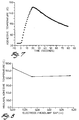
- Figure 7 is a graph of temperature verses time for a urethane adhesive UR4510 manufactured by H.B. Fuller when subjected to an electric field of 27.12 Hz, 5700 volts, for 20 seconds beginning from room temperature.
- This fringe electric field is weaker than the electric field directly between the electrodes. The fringe electric field remains strong enough to heat the adhesive and achieve at least a partial cure.
- the invention has been described in terms of bonding a thermoplastic reflector to a thermoplastic lens.
- the invention is usable for bonding a wide variety of materials including thermosets, ceramics, glass, metal, wood and cloth.
- automotive glass could be rapidly bonded to plastic for manufacturing modular vehicle windows.
- the heating rate of a material in a Radio Frequency (RF) electric field heats primarily the adhesive layers.
- RF Radio Frequency
- the low dielectric loss and low thermal conductivity of the typical glass or ceramic materials make RF dielectric bonding ideal for such applications. It is important to control the duration and the strength of the RF exposure such that the heat generated in the adhesives does not raise the temperature of the thermoplastic member above the temperature at which it distorts.
- dielectric loss enhancers high polarity additives formulated in the adhesives.
- Typical dielectric loss enhancers include halogenated organic compounds and ionic compounds which can be incorporated in the adhesive formulation.
Abstract
Description
- The present invention relates to fringe field dielectric heating of an adhesive. More specifically, the invention relates to using a segmented electrode adjacent an automotive lamp reflector creating a fringe electric field for heating a thermosetting adhesive.
- Reference is made to U.S. applications serial No. 07/633,742 titled "DIELECTRIC CURING OF ADHESIVES" and serial No. 07/632,830 titled "REVERSIBLE ATTACHMENT USING DIELECTRIC HEATING."
- U.S. Patent Nos. 4,941,936 and 4,941,937 both issued July 17, 1990 teach a method of heating an adhesive between two fiber reinforced plastic members using a high frequency electric field. The electric field causes the dielectric heating of the adhesive between the fiber reinforced plastic members. The members are placed between two electrodes and an electric field is passed linearly from the top electrode through the members to the bottom electrode.
- The present invention is specifically intended for the manufacture of automotive headlamp assemblies. Current automotive headlamps are manufactured by bonding a metallized reflector to a transparent lens. Both the reflector and the lens are generally made of a thermoplastic material such as polycarbonate. A two component epoxy adhesive is placed between the lens and reflector and allowed to cure. After the lamp assembly has cured, it is pressurised to approximately 5 p.s.i. to detect any adhesive failures or leakage. Pressure testing of the lamp assembly requires sufficient cure of the adhesive to withstand the increased pressure.
- It is an object of the present invention to provide a rapid method of curing an adhesive between two thermoplastic members. It is another object of the present invention to provide a method for dielectrically heating an adhesive using a fringe electric field. It is a further object of the present invention to provide a method for dielectrically heating an adhesive between an automotive reflector and lens assembly.
- The present invention provides for a method of dielectrically heating an adhesive between first and second members by first placing an adhesive bead between mating surfaces of the first and second member. A first electrode is placed adjacent to the first member and a high frequency electric field is applied between the first electrode and a second electrode sufficient to dielectrically heat the adhesive.
- The invention also provides an apparatus for bonding a first member to a second member wherein the first member has structural portions overlying mating surfaces of the first and second members. The apparatus comprises a segmented electrode having two or more pieces. The pieces are moveable between an open and a closed position. The segmented electrode is spaced adjacent the structural portions of the first member when the pieces are in the closed position. A moving means moves the pieces between opened and closed positions. A second electrode is spaced parallel to the segmented electrode. One or more high frequency generators are connected between the segmented and second electrodes. The generator supplies a high frequency electric field which is sufficient to heat a dielectrically heatable adhesive positioned between the mating surfaces.
- Conventional dielectric heating techniques teach the application of a high frequency electric field to heat a material placed between two electrodes. On modern automotive headlamp assemblies, it is often difficult or impossible to position an electrode overlying both surfaces of a bond line. Brackets and supporting structures on the automotive reflector often directly overlie the bond line. In an attempt to reduce the overall height profile of a lamp assembly, the perimeter lip portion of a lens has been reduced or eliminated. The typical structure of an automotive reflector and lens assembly do not permit the placement of electrodes to overlie mating surfaces between the lens and reflector.
- The present invention utilises the fringe electric field between two electrodes to dielectrically heat an adhesive placed adjacent the electrodes. Fringe field dielectric heating is herein defined as the dielectric heating of a material spaced adjacent two electrodes. The electric field dielectrically heating the adhesive travels in an arcuate path adjacent one or both of the electrodes.
- To utilise fringe field dielectric heating, it is necessary to space the electrodes as near to the bond line as possible. In situations where structural portions such as brackets or structural members overlie the bond line, an electrode made up of two or more pieces is necessary. An electrode comprising two or more pieces is herein defined as segmented. The pieces are electrically connected to one another and the electric field generated by a segmented electrode is essentially the same as that generated by a one-piece electrode.
- The pieces are moveable between an open and a closed position. The reflector is placed between the open pieces. The pieces are moved to their closed position so as to closely follow the perimeter of the reflector. An adhesive is placed between mating surfaces of the reflector and lens. The lens is placed within a second electrode. The second electrode may be either segmented or unsegmented depending upon the design of the particular lens. A high frequency electric field between 10 and 100 MHz is applied between the segmented and second electrode. An electric field travelling in an arcuate path between the segmented and second electrode passes through mating surfaces of the reflector and lens and dielectrically heats the adhesive.
- The adhesive can be 60 to 85 percent cured after only 10 to 20 seconds, depending on the specific adhesive, electrode configuration and electric field strength. This permits the near simultaneous bonding and pressure testing of a lens assembly without removing the assembly from the fixturing tool or waiting an extended period of time for the adhesive to cure. Bonding failures may be diagnosed quickly and reduce the overall volume of rejected parts.
- Segmenting the electrode permits the use of dielectric heating for applications previously thought unsuitable. Applications where structural portions overlie bond lines may still be dielectrically heated using fringe field dielectric heating.
- The invention will now be described further, by way of example, with reference to the accompanying drawings, in which :
- Figure 1 is an exploded view of the bonding apparatus of the present invention.
- Figure 2 is a perspective view of an automotive lens assembly undergoing dielectric heating.
- Figure 3 is a cross-sectional view of the automotive lens assembly taken along the line III-III in Figure 2.
- Figure 4 is a cross-sectional view of the automotive lens assembly taken along the line IV-IV of Figure 2.
- Figure 5 shows fringe electric fields for evenly spaced electrodes.
- Figure 6 shows fringe electric fields for staggered electrodes.
- Figure 7 is a graph of temperature verses time for a urethane adhesive subjected to an electric field.
- Figure 8 is a graph of maximum temperature rise verse the amount of staggering (d) when an electrode is moved a distance away from vertical alignment.
- Figure 1 shows an exploded view of an
automotive headlamp assembly 10 includingreflector 12 andlens 14. A bead of dielectrically heatable adhesive is placed between mating surfaces ofreflector 12 andlens 14. Suitable adhesives include epoxy and urethane adhesives. Of those commercially available, a two-component epoxy adhesive, Fusor 320/322, manufactured by Lord Chemical Company and two-component urethane adhesive, PG-6500 manufactured by Ashland Chemical Company are suitable with the present invention. Other types of thermoset as well as thermoplastic adhesives which are responsive to dielectric heating are also suitable in the present invention. -
Lens 14 is generally made of a transparent polycarbonate material having a glass transition temperature (Tg) of approximately 150/C. Reflector 12 is manufactured from a polycarbonate based material and has a Tg of approximately 145/C. The interior surface of reflector 12 (not shown) is aluminized to provide a reflective surface.Brackets 26 are used to attachheadlamp assembly 10 to a vehicle.Brackets 26 containstructural portions 24 which overlie the mating surfaces oflens 14 andreflector 12. -
Lens 14 has a generally rectangular shape.Lens 14 is received byelectrode 18. The interior ofelectrode 18 closely follows the exterior perimeter oflens 14. -
Segmented electrode 16 is made from twopieces Pieces Pins 32 are received bysockets 34 to form an integral electrically connected electrode when in the closed position. Cut-outsections 28 permit segmentedelectrode 16 to closely overlie the perimeter portion ofreflector 12. Cut-outsections 28 receivestructural portions 24. -
Segmented electrode 16 is affixed to a tool (not shown) which permits the relative movement betweenpieces Pieces pieces - A high frequency
electric generator 22 electrically connects segmentedelectrode 16 andelectrode 18.Generator 22 is capable of operating between the frequencies of 10 MHz and 100 MHz and between 1,000 and 30,000 volts. Suitable commercially available high frequency electric generator with a pneumatic press is manufactured by Kabar Manufacturing Company, Farmingville, New York. -
Electrode 18 receiveslens 14. A bead of dielectrically heatable adhesive 30 is placed between mating surfaces oflens 14 andreflector 12. Withpieces reflector 12 is placed onlens 14. A pneumatic press urgesreflector 12 ontolens 14 as shown in Figure 2.Pieces reflector 12. An electric field of approximately 27.12 MHz is applied betweenelectrodes - The electric field is sufficient to raise the curing temperature of adhesive 30 to approximately 150 to 175/C. After this time, adhesive 30 has sufficiently cured to provide a pressure resistant bond between
reflector 12 andlens 14.Lens assembly 10 may be subjected to pressure testing throughbulb socket 36. This pressure testing includes applying a positive air pressure of approximately 5 psi to the interior portion oflens assembly 10. -
Adhesive 30 is heated by an electric field. Shown in Figures 3 and 4 are cross-sectional views oflens assembly 10 undergoing dielectric heating. Shown in Figure 3 is a sectional view along the line III-III in Figure 2.Lens 14 comprises aU-shaped channel 40 which receives aprojection 38 onreflector 12. WithinU-shaped channel 40 is adhesive 30.Channel 40 andprojection 38 provide the mating surfaces betweenlens 14 andreflector 12. The mating surfaces betweenchannel 40 andprojection 38 has been illustrated in Figure 1 as having a generally planar shape, but these mating surfaces maybe contoured to have a three dimensional shape. -
Segmented electrode 16 overliesprojection 38.Electrode 18 partially overlieschannel 40. At least a portion of the electric field betweenelectrode 18 andsegmented electrode 16 travels linearly throughadhesive 30. - Shown in Figure 4 is a sectional view of
lens assembly 10 taken along the line IV-IV in Figure 2.Reflector 12 includesstructural portions 24.Lens 14 does not contain a lip area to permitelectrode 18 to partially overliechannel 40. The interior portions ofelectrodes electrode 18 andsegmented electrode 16. - It is known that the electric field between two oppositely charged points includes a portion which travels in an arcuate path between the charged points. See D. Halliday and R. Resnick, Physics, (John Wiley and Sons, 1978,
Chapters 28 and 29 herein incorporated by reference. This arcuate path is herein referred to as fringe electric fields. Shown in Figures 5 and 6 is a graphic representation of fringe electric fields. Figure 5 shows an electric field between two vertically aligned electrodes. Electric field vector A shows a linear path between the positively charged electrode to the negatively charged electrode. The electric field adjacent the electrodes becomes weaker in intensity and more arcuate in shape. Electric field vectors B, C, and D show the electric field adjacent the electrodes 16', 18'. - Figure 6 shows an electric field between staggered electrodes. Electric field vector E shows a linear electric field between the positive electrode and negative electrode. Electric field vectors F, G, and H show the electric field adjacent the electrodes 16'', 18''. A similar electric field would exist when the polarity of the electrodes is reversed. Figures 5 and 6 demonstrate the ability of an electric field to extend adjacent to the electrodes. This phenomenon permits the dielectric heating of a material spaced adjacent the electrodes.
- Figure 7 is a graph of temperature verses time for a urethane adhesive UR4510 manufactured by H.B. Fuller when subjected to an electric field of 27.12 Hz, 5700 volts, for 20 seconds beginning from room temperature. Figure 8 is a graph of maximum temperature rise verse the amount of staggering (d) when segmented
electrode 16 as shown in Figure 3 is moved a distance away fromreflector 12 between d=0 and d=0.2 inches. This fringe electric field is weaker than the electric field directly between the electrodes. The fringe electric field remains strong enough to heat the adhesive and achieve at least a partial cure. - The invention has been described in terms of bonding a thermoplastic reflector to a thermoplastic lens. The invention is usable for bonding a wide variety of materials including thermosets, ceramics, glass, metal, wood and cloth. For example, automotive glass could be rapidly bonded to plastic for manufacturing modular vehicle windows. The heating rate of a material in a Radio Frequency (RF) electric field heats primarily the adhesive layers. When joining inorganic members such as glass or ceramic components, the low dielectric loss and low thermal conductivity of the typical glass or ceramic materials make RF dielectric bonding ideal for such applications. It is important to control the duration and the strength of the RF exposure such that the heat generated in the adhesives does not raise the temperature of the thermoplastic member above the temperature at which it distorts. When bonding plastic materials with relatively high dielectric loss, it is possible to control the dielectric heating so that the adhesive heats much faster than the surrounding materials by choosing an adhesive containing dielectric loss enhancers (high polarity additives formulated in the adhesives). Typical dielectric loss enhancers include halogenated organic compounds and ionic compounds which can be incorporated in the adhesive formulation.
Claims (10)
- A method of dielectrically heating an adhesive (30) between first and second members (12,14) comprising the steps of:
placing said adhesive (30) between mating surfaces of said first and second members (12,14);
placing a first electrode (16) adjacent said first member (12); and
applying a high frequency electric field between said first electrode (16) and a second electrode (18) sufficient to dielectrically heat said adhesive (30). - A method of bonding a first member to a second member, said first member having structural portions overlying mating surfaces of said first and second members comprising the steps of:
providing a segmented electrode, said segmented electrode having two or more pieces, said pieces being movable between an open and closed position;
applying adhesive between said mating surfaces;
opening said segmented electrode;
placing said first member between said pieces;
closing said pieces so that said segmented electrode is adjacent said structural portions and closely conforms to the perimeter of said first member; and
applying a high frequency electric field between said segmented electrode and a second electrode sufficient to dielectrically heat said adhesive. - A method as claimed in 1 or 2 wherein said second electrode is placed adjacent said second member.
- A method as claimed in claim 1, wherein said second electrode is spaced or partially overlie said adhesive.
- A method as claimed in claim 1 or 2, wherein said electrodes direct a fringe electric field through said adhesive.
- A method as claimed in claim 1, wherein said first electrode is segmented.
- A method as claimed in claim 5, wherein said segmented electrode comprises two or more pieces, said pieces being spaced apart to receive said first member and then moved together adjacent said first member, and further comprising the step of electrically connecting said pieces.
- A method as claimed in claim 1 or 2, wherein said first member is a reflector and said second member is a lens.
- An apparatus for bonding a first member (12) to a second member (14), said first member (12) having structural portions (24) overlying mating surfaces of said first and second members (12,14) comprising:
a segmented electrode (16), said segmented electrode having two or more pieces (19,20), said pieces (19,20) being movable between an open and closed position, said segmented electrode (19,20) spaced adjacent said structural portions (24) of said first member (12) when said pieces (19,20) are in the closed position;
means for moving said pieces (19,20) between the open and closed positions;
a second electrode (18) parallel with said segmented electrode (16); and
one or more high frequency generators (22) connected between said segmented (16) and second electrode (18), said generator (22) supplying a high frequency electric field which is sufficient to heat a dielectrically heatable adhesive (30) positioned between said mating surfaces. - An apparatus as claimed in claim 9, wherein said first member is an automotive lamp reflector and said second member is a lens.
Applications Claiming Priority (2)
| Application Number | Priority Date | Filing Date | Title |
|---|---|---|---|
| US07/696,486 US5223684A (en) | 1991-05-06 | 1991-05-06 | Method and apparatus for dielectrically heating an adhesive |
| US696486 | 1991-05-06 |
Publications (2)
| Publication Number | Publication Date |
|---|---|
| EP0512678A1 true EP0512678A1 (en) | 1992-11-11 |
| EP0512678B1 EP0512678B1 (en) | 1996-06-26 |
Family
ID=24797270
Family Applications (1)
| Application Number | Title | Priority Date | Filing Date |
|---|---|---|---|
| EP19920302742 Expired - Lifetime EP0512678B1 (en) | 1991-05-06 | 1992-03-27 | Fringe field dielectric heating |
Country Status (3)
| Country | Link |
|---|---|
| US (1) | US5223684A (en) |
| EP (1) | EP0512678B1 (en) |
| DE (1) | DE69211768T2 (en) |
Cited By (3)
| Publication number | Priority date | Publication date | Assignee | Title |
|---|---|---|---|---|
| GB2315121B (en) * | 1996-07-08 | 1998-06-03 | Koito Mfg Co Ltd | Vehicular lamp |
| WO2002081899A1 (en) * | 2001-04-04 | 2002-10-17 | Dow Global Technologies Inc. | Adhesively bonded engine intake manifold assembly |
| WO2003076167A1 (en) * | 2002-03-08 | 2003-09-18 | Henkel Kommanditgesellschaft Auf Aktien | Method for joining transparent plastic substrates |
Families Citing this family (12)
| Publication number | Priority date | Publication date | Assignee | Title |
|---|---|---|---|---|
| US5488221A (en) * | 1995-01-18 | 1996-01-30 | Amabile; Louis | Slot interlock connectors for RF welding electrodes |
| US6021753A (en) * | 1996-07-03 | 2000-02-08 | Ford Global Technologies, Inc. | Adhesively bonded plastic automotive air intake assembly |
| US5750970A (en) * | 1996-07-03 | 1998-05-12 | Ford Global Technologies, Inc. | Method for dielectrically heating an adhesive |
| US5811792A (en) * | 1997-01-02 | 1998-09-22 | Wisconsin Label Corporation | Method and apparatus for accessing contents of envelopes and other similarly concealed information |
| US6026881A (en) * | 1997-08-13 | 2000-02-22 | Lord Corporation | Apparatus for monitoring bonding |
| US6348679B1 (en) * | 1998-03-17 | 2002-02-19 | Ameritherm, Inc. | RF active compositions for use in adhesion, bonding and coating |
| US5947073A (en) * | 1998-04-06 | 1999-09-07 | Ford Global Technologies, Inc. | Adhesively bonded plastic automotive air intake assembly |
| US6649888B2 (en) | 1999-09-23 | 2003-11-18 | Codaco, Inc. | Radio frequency (RF) heating system |
| US7360519B2 (en) * | 2003-07-10 | 2008-04-22 | Dow Global Technologies, Inc. | Engine intake manifold assembly |
| US20120227901A1 (en) * | 2006-06-01 | 2012-09-13 | Ceralink, Inc. | Method of lamination using radio frequency heating and pressure |
| CN103965792B (en) * | 2013-01-29 | 2018-11-09 | 康廷南拓结构塑料有限公司 | Air adhering method |
| JP2017045714A (en) * | 2015-08-28 | 2017-03-02 | 東洋製罐グループホールディングス株式会社 | High frequency dielectric heating method |
Citations (4)
| Publication number | Priority date | Publication date | Assignee | Title |
|---|---|---|---|---|
| BE471426A (en) * | ||||
| FR1582931A (en) * | 1968-08-21 | 1969-10-10 | ||
| GB2048272A (en) * | 1979-04-26 | 1980-12-10 | Bosch Gmbh Robert | Process for the Hardening of Reactive Resins |
| US4941936A (en) * | 1988-04-28 | 1990-07-17 | The Budd Company | Method for bonding FRP members via dielectric heating |
Family Cites Families (23)
| Publication number | Priority date | Publication date | Assignee | Title |
|---|---|---|---|---|
| CA800129A (en) * | 1968-11-26 | Commissariat A L'energie Atomique | High-field hyperfrequency generator | |
| US2473188A (en) * | 1944-06-17 | 1949-06-14 | Rca Corp | Radio-frequency dielectric heater with constant heating rate control |
| US2504754A (en) * | 1946-09-19 | 1950-04-18 | Singer Mfg Co | Control system for electrostatic bonding |
| US2920172A (en) * | 1956-10-04 | 1960-01-05 | Gen Motors Corp | Dielectric heating and pressing die structure |
| US3291671A (en) * | 1962-09-04 | 1966-12-13 | Myer H Hecht | Dielectric fusing of plastic films |
| US4036676A (en) * | 1975-04-14 | 1977-07-19 | William Pennington | Heat sealing of plastic sheets |
| SU878187A3 (en) * | 1977-05-17 | 1981-10-30 | Бизон-Верке Бэре Унд Гретен Гмбх Унд Ко,Кг (Фирма) | Device for continuous production of wood particle boards |
| GB2026386B (en) * | 1978-06-08 | 1982-09-22 | Nissan Motor | Panel assembling method and apparatus |
| JPS55100694A (en) * | 1979-01-26 | 1980-07-31 | Hitachi Ltd | Oscillator circuit for induction heater |
| JPS5787321A (en) * | 1980-11-21 | 1982-05-31 | Nissan Motor Co Ltd | Fusion-bonding method of skin material and foamed resin sheet |
| JPS6131214A (en) * | 1984-07-23 | 1986-02-13 | Toyota Motor Corp | Manufacture of vehicle decorating lace |
| US4650947A (en) * | 1985-02-18 | 1987-03-17 | Hutton Roger L | Induction tacking method and apparatus |
| US4602139A (en) * | 1984-09-28 | 1986-07-22 | Hutton Roger L | Induction bonding method and apparatus |
| US4654495A (en) * | 1984-09-28 | 1987-03-31 | Hutton Roger L | Sheet metal tacking and bonding method and apparatus |
| US4626642A (en) * | 1985-10-08 | 1986-12-02 | General Motors Corporation | Microwave method of curing a thermoset polymer |
| US4814587A (en) * | 1986-06-10 | 1989-03-21 | Metcal, Inc. | High power self-regulating heater |
| US4762864A (en) * | 1986-06-19 | 1988-08-09 | Ashland Oil Inc. | High performance induction curable two-component structural adhesive with nonsagging behavior |
| US4878978A (en) * | 1986-06-19 | 1989-11-07 | Ashland Oil, Inc. | Bonding method employing high performance induction curable two-component structural adhesive with nonsagging behavior |
| US4798925A (en) * | 1986-07-04 | 1989-01-17 | Kabushiki Kaisha Meidensha | Method for measuring effective heating power for high frequency heating |
| US4816633A (en) * | 1987-03-06 | 1989-03-28 | Tocco, Inc. | Method of monitoring induction heating cycle |
| US4771150A (en) * | 1987-06-29 | 1988-09-13 | Tachi-S Co., Ltd. | Method of forming trim cover assembly for automotive seat |
| US4749833A (en) * | 1987-08-07 | 1988-06-07 | Tocco, Inc. | Induction heating for adhesive bonding |
| US4941937A (en) * | 1988-04-28 | 1990-07-17 | The Budd Company | Method for bonding reinforcement members to FRP panels |
-
1991
- 1991-05-06 US US07/696,486 patent/US5223684A/en not_active Expired - Fee Related
-
1992
- 1992-03-27 DE DE1992611768 patent/DE69211768T2/en not_active Expired - Fee Related
- 1992-03-27 EP EP19920302742 patent/EP0512678B1/en not_active Expired - Lifetime
Patent Citations (4)
| Publication number | Priority date | Publication date | Assignee | Title |
|---|---|---|---|---|
| BE471426A (en) * | ||||
| FR1582931A (en) * | 1968-08-21 | 1969-10-10 | ||
| GB2048272A (en) * | 1979-04-26 | 1980-12-10 | Bosch Gmbh Robert | Process for the Hardening of Reactive Resins |
| US4941936A (en) * | 1988-04-28 | 1990-07-17 | The Budd Company | Method for bonding FRP members via dielectric heating |
Cited By (5)
| Publication number | Priority date | Publication date | Assignee | Title |
|---|---|---|---|---|
| GB2315121B (en) * | 1996-07-08 | 1998-06-03 | Koito Mfg Co Ltd | Vehicular lamp |
| WO2002081899A1 (en) * | 2001-04-04 | 2002-10-17 | Dow Global Technologies Inc. | Adhesively bonded engine intake manifold assembly |
| US6543404B2 (en) | 2001-04-04 | 2003-04-08 | Dow Global Technologies, Inc. | Adhesively bonded engine intake manifold assembly |
| CN100334343C (en) * | 2001-04-04 | 2007-08-29 | 陶氏环球技术公司 | Adhesively bonded engine intake manifold assembly |
| WO2003076167A1 (en) * | 2002-03-08 | 2003-09-18 | Henkel Kommanditgesellschaft Auf Aktien | Method for joining transparent plastic substrates |
Also Published As
| Publication number | Publication date |
|---|---|
| US5223684A (en) | 1993-06-29 |
| DE69211768T2 (en) | 1996-10-24 |
| EP0512678B1 (en) | 1996-06-26 |
| DE69211768D1 (en) | 1996-08-01 |
Similar Documents
| Publication | Publication Date | Title |
|---|---|---|
| EP0512678B1 (en) | Fringe field dielectric heating | |
| KR970009932B1 (en) | Method and apparatus for bonding a cured f.r.p. part to a reinforcement member | |
| EP0339494A2 (en) | Method and apparatus for bonding FRP members | |
| US6312548B1 (en) | Conductive insert for bonding components with microwave energy | |
| US5266764A (en) | Flexible heating head for induction heating | |
| US5707473A (en) | Method for making a panel assembly | |
| US5534097A (en) | Method of bonding a seat trim cover to a foam cushion utilizing magnetic induction bonding | |
| EP0171604B1 (en) | Thermoset bonding agent for non-distortion joining of selfsupporting thermoset component parts | |
| CA2056838A1 (en) | Dielectric curing of adhesives | |
| HU221878B1 (en) | Method and apparatus for welding plastic framework elements cut on the mitre and having seals drawn in | |
| EP0686227A1 (en) | Vehicular panel assembly, method and apparatus for making same | |
| ES2105411T3 (en) | A DEVICE TO CLOSE THROUGH THERMOPLASTIC MATERIALS. | |
| US5865940A (en) | Reversible attachment using dielectric heating | |
| EP0440410B1 (en) | Method for joining FRP material with vulcanized rubber | |
| KR980010097A (en) | Car lamp | |
| US5869814A (en) | Post-weld annealing of thermoplastic welds | |
| GB2004497A (en) | Method of fusion bonding non-elastomeric thermoplastic elements with a block structure elastomeric bonding element interposed at the bonding interface | |
| US5712469A (en) | Method of curing inaccessible thermoset adhesive joints using radio frequency dielectric heating | |
| US6365883B1 (en) | U-shaped adhesive bonding apparatus | |
| EP0723494B1 (en) | Apparatus for and method of edge encapsulating a glazing panel | |
| EP0850749A2 (en) | Improved sealed vehicle lamp and assembly method therefor | |
| US3053960A (en) | Dielectric process and apparatus for forming materials | |
| CN218918978U (en) | Edge sealing and reinforcing device | |
| GB2025500A (en) | Improvements in and relating to multi-panel units | |
| US11697250B2 (en) | Systems and methods for joining a first structure and a second structure with vacuum dispersion process |
Legal Events
| Date | Code | Title | Description |
|---|---|---|---|
| PUAI | Public reference made under article 153(3) epc to a published international application that has entered the european phase |
Free format text: ORIGINAL CODE: 0009012 |
|
| AK | Designated contracting states |
Kind code of ref document: A1 Designated state(s): DE FR GB |
|
| 17P | Request for examination filed |
Effective date: 19930427 |
|
| 17Q | First examination report despatched |
Effective date: 19941212 |
|
| GRAH | Despatch of communication of intention to grant a patent |
Free format text: ORIGINAL CODE: EPIDOS IGRA |
|
| GRAH | Despatch of communication of intention to grant a patent |
Free format text: ORIGINAL CODE: EPIDOS IGRA |
|
| GRAA | (expected) grant |
Free format text: ORIGINAL CODE: 0009210 |
|
| AK | Designated contracting states |
Kind code of ref document: B1 Designated state(s): DE FR GB |
|
| ET | Fr: translation filed | ||
| REF | Corresponds to: |
Ref document number: 69211768 Country of ref document: DE Date of ref document: 19960801 |
|
| PLBE | No opposition filed within time limit |
Free format text: ORIGINAL CODE: 0009261 |
|
| STAA | Information on the status of an ep patent application or granted ep patent |
Free format text: STATUS: NO OPPOSITION FILED WITHIN TIME LIMIT |
|
| 26N | No opposition filed | ||
| PGFP | Annual fee paid to national office [announced via postgrant information from national office to epo] |
Ref country code: DE Payment date: 20000224 Year of fee payment: 9 |
|
| PGFP | Annual fee paid to national office [announced via postgrant information from national office to epo] |
Ref country code: GB Payment date: 20000229 Year of fee payment: 9 |
|
| PGFP | Annual fee paid to national office [announced via postgrant information from national office to epo] |
Ref country code: FR Payment date: 20000309 Year of fee payment: 9 |
|
| REG | Reference to a national code |
Ref country code: FR Ref legal event code: TP Ref country code: FR Ref legal event code: CD |
|
| PG25 | Lapsed in a contracting state [announced via postgrant information from national office to epo] |
Ref country code: GB Free format text: LAPSE BECAUSE OF NON-PAYMENT OF DUE FEES Effective date: 20010327 |
|
| GBPC | Gb: european patent ceased through non-payment of renewal fee |
Effective date: 20010327 |
|
| PG25 | Lapsed in a contracting state [announced via postgrant information from national office to epo] |
Ref country code: FR Free format text: LAPSE BECAUSE OF NON-PAYMENT OF DUE FEES Effective date: 20011130 |
|
| REG | Reference to a national code |
Ref country code: FR Ref legal event code: ST |
|
| PG25 | Lapsed in a contracting state [announced via postgrant information from national office to epo] |
Ref country code: DE Free format text: LAPSE BECAUSE OF NON-PAYMENT OF DUE FEES Effective date: 20020101 |