EP0511506B1 - Device for location of the focal region in lithotripsy - Google Patents
Device for location of the focal region in lithotripsy Download PDFInfo
- Publication number
- EP0511506B1 EP0511506B1 EP92105570A EP92105570A EP0511506B1 EP 0511506 B1 EP0511506 B1 EP 0511506B1 EP 92105570 A EP92105570 A EP 92105570A EP 92105570 A EP92105570 A EP 92105570A EP 0511506 B1 EP0511506 B1 EP 0511506B1
- Authority
- EP
- European Patent Office
- Prior art keywords
- image
- ultrasound
- images
- movement processes
- detection
- Prior art date
- Legal status (The legal status is an assumption and is not a legal conclusion. Google has not performed a legal analysis and makes no representation as to the accuracy of the status listed.)
- Expired - Lifetime
Links
Images
Classifications
-
- A—HUMAN NECESSITIES
- A61—MEDICAL OR VETERINARY SCIENCE; HYGIENE
- A61B—DIAGNOSIS; SURGERY; IDENTIFICATION
- A61B17/00—Surgical instruments, devices or methods, e.g. tourniquets
- A61B17/22—Implements for squeezing-off ulcers or the like on the inside of inner organs of the body; Implements for scraping-out cavities of body organs, e.g. bones; Calculus removers; Calculus smashing apparatus; Apparatus for removing obstructions in blood vessels, not otherwise provided for
- A61B17/225—Implements for squeezing-off ulcers or the like on the inside of inner organs of the body; Implements for scraping-out cavities of body organs, e.g. bones; Calculus removers; Calculus smashing apparatus; Apparatus for removing obstructions in blood vessels, not otherwise provided for for extracorporeal shock wave lithotripsy [ESWL], e.g. by using ultrasonic waves
- A61B17/2256—Implements for squeezing-off ulcers or the like on the inside of inner organs of the body; Implements for scraping-out cavities of body organs, e.g. bones; Calculus removers; Calculus smashing apparatus; Apparatus for removing obstructions in blood vessels, not otherwise provided for for extracorporeal shock wave lithotripsy [ESWL], e.g. by using ultrasonic waves with means for locating or checking the concrement, e.g. X-ray apparatus, imaging means
Definitions
- the invention relates to a device for locating the focal region of the shock waves generated in a shock wave source relative to a concrement located in the body of a living being.
- ESWL extracorporeal shock wave lithotripsy
- ESWL extracorporeal shock wave lithotripsy
- An exact positioning of the concrement to be treated is not possible in such cases, the ESWL effectiveness is correspondingly low.
- Direct imaging of shock wave propagation / focusing in the body cannot be carried out with the imaging methods known in medicine.
- the focal area is located indirectly through the movement processes in the body induced by the shock waves.
- the ultrasound Doppler method used here only the radial speed with respect to the ultrasound scanner from which the ultrasound waves originate and whose echoes are received can be measured.
- the invention has for its object to provide a device with which the focal area of the shock wave source can be reliably located and the concrement can be safely positioned in the focal area.
- the shock wave propagation / focusing within the body is indirectly imaged by detecting the movement processes induced by the shock waves. Movements can be induced in the stone material, in the fluid surrounding the stone or in the body tissue. Another possibility is the movement of cavitation bubbles generated in the shock wave field. Since these movements are most pronounced in the focal area, this region can be located.
- the detection of the induced movement processes inside the patient's body is carried out non-invasively by evaluating the ultrasound B-image used for the ESWL stone location, hereinafter also called the B-image.
- the movements are determined in a device for detecting the movement processes induced by the shock waves by segmenting and correlating successive B-images.
- the comparison is not limited to direct subsequent images B i , B i + 1 ; images B i , B i + k with k> 1 can advantageously also be compared.
- the determined speed values are used to generate a color-coded speed image and can be superimposed on the ultrasound B-image. With such a speed picture, any combination of Amount / speed assigned a color / intensity combination.
- the imaging errors inherent in the B-picture due to sound refraction and sound diffraction are of no influence here for the localization of the focal area, since the relative position of the focal area to the concrement is decisive for the ESWL positioning.
- 1 shows schematically the movement processes induced by the shock waves, which can serve to locate the focal area.
- the focal area is surrounded by a dashed line and the directions of movement are shown by arrows.
- 1a shows the dynamics of cavitation bubbles that arise in a liquid within the focal region of the shock waves.
- the cavitation bubbles act as a moving ultrasound contrast medium and are therefore visible in the ultrasound B-image.
- 1b shows the dynamics of stone material within the focal area. Large stones (top illustration) behave essentially immobile, so that the cavitation bubbles that form in the surrounding liquid serve primarily to locate the focal area.
- Fig. 1b lower figure, the dynamics of stone fragments is shown. Here both the movement of the stone fragments and the cavitation bubbles in the surrounding liquid are suitable for locating the focal area.
- FIG. 2 shows the block diagram of a device according to the invention.
- the concrement K to be treated is located in the patient's body PK .
- Ultrasonic shock waves are generated, focused and aligned with the concretion K in the shock wave source SQ .
- An ultrasound scanner SC sends ultrasound waves and receives their echoes, which are further processed in the ultrasound device US to form an ultrasound B-image of the area of the body under consideration.
- a trigger unit TR limits the motion detection to a time window after the shock waves are triggered in the shock wave source SQ .
- the calculated speed values are color-coded in the device FK , so that the area of the patient's body PK shown in the B-pictures is converted into a speed picture.
- the color-coded image is then postprocessed in device NV (eg smoothing, interpolation).
- NV eg smoothing, interpolation
- FIG. 3 shows the block diagram of an embodiment of the device BD for detecting the movement processes induced by the shock waves.
- the Image memory SP which is designed, for example, as a sliding memory
- two successive B-images B i , B i + k , with k> 1, are stored.
- the assumed focal area also referred to below as ROI (Region-Of-Interest)
- ROI can be defined within the B-picture via a user interface BI , so that movement processes are only detected within this ROI.
- the two ROIs are divided into image segments of a suitable size according to a square grid, for example.
- a segment usually comprises several pixels.
- the correlation coefficients between each segment in the first image B i and the image environment of the corresponding segment in the subsequent image B i + k are then calculated. The calculation is based on the grayscale values of the individual pixels.
- the difference vector between the segment in the first image B i and the area of maximum correlation in the subsequent image is used to calculate the amount and speed of the motion vector. Estimates that result from the correlation process, but are physically nonsensical, can be recognized and filtered out.
- the entirety of the two-dimensional speed vectors determined are converted into a speed image in the subsequent color coding.
- a color / intensity combination for direction and amount is assigned to each image segment.
- the trigger unit TR limits movement detection to times relevant to shock waves.
- the device according to the invention has the advantage of detecting two-dimensional speed components. This means that both the B-scan of an in-line scanner and an off-axis scanner can be used can be used without any loss in the detection of movement processes in any preferred direction.
Description
Die Erfindung betrifft eine Vorrichtung zur Ortung des Fokalbereichs der in einer Stoßwellenquelle erzeugten Stoßwellen relativ zu einem im Körper eines Lebewesens befindlichen Konkrement.The invention relates to a device for locating the focal region of the shock waves generated in a shock wave source relative to a concrement located in the body of a living being.
Der ESWL-Fokalbereich (ESWL = extrakorporale Stoßwellen-Lithotripsie) kann, besonders bei anatomisch ungünstigen Verhältnissen, erheblich vom geometrisch berechneten Fokus abweichen. Eine exakte Positionierung des zu therapierenden Konkrements ist in solchen Fällen nicht möglich, die ESWL-Effektivität ist entsprechend gering. Eine direkte Abbildung der Stoßwellenausbreitung/-Fokussierung im Körper ist mit den in der Medizin bekannten Bildgebungsverfahren nicht durchführbar.The ESWL focal area (ESWL = extracorporeal shock wave lithotripsy) can deviate significantly from the geometrically calculated focus, especially in anatomically unfavorable conditions. An exact positioning of the concrement to be treated is not possible in such cases, the ESWL effectiveness is correspondingly low. Direct imaging of shock wave propagation / focusing in the body cannot be carried out with the imaging methods known in medicine.
In der EP 367 116 wird der Fokalbereich indirekt durch die von den Stoßwellen induzierten Bewegungsvorgänge im Körper geortet. Bei dem dabei angewendeten Ultraschall-Dopplerverfahren kann allerdings nur die Radialgeschwindigkeit bezüglich des Ultraschallscanners gemessen werden, von dem die Ultraschallwellen ausgehen und deren Echos empfangen werden.In EP 367 116 , the focal area is located indirectly through the movement processes in the body induced by the shock waves. With the ultrasound Doppler method used here, however, only the radial speed with respect to the ultrasound scanner from which the ultrasound waves originate and whose echoes are received can be measured.
Der Erfindung liegt die Aufgabe zugrunde, eine Vorrichtung zu schaffen, mit der der Fokalbereich der Stoßwellenquelle zuverlässig geortet und das Konkrement sicher im Fokalbereich positioniert werden kann.The invention has for its object to provide a device with which the focal area of the shock wave source can be reliably located and the concrement can be safely positioned in the focal area.
Diese Aufgabe wird erfindungsgemäß mit einer Vorrichtung mit den kennzeichnenden Merkmalen des Anspruch 1 gelöst. Ausgestaltungen der Erfindung sind Gegenstände von Unteransprüchen.This object is achieved with a device having the characterizing features of claim 1. Embodiments of the invention are the subject of subclaims.
Mit der erfindungsgemäßen Vorrichtung wird die Stoßwellenausbreitung/-Fokussierung innerhalb des Körpers indirekt abgebildet durch Erfassung der durch die Stoßwellen induzierten Bewegungsvorgänge.
Bewegungen können induziert werden im Steinmaterial, in der das Konkrement umgebenden Flüssigkeit oder im Körpergewebe. Eine weitere Möglichkeit ist die Bewegung von im Stoßwellenfeld erzeugten Kavitationsblasen. Da diese Bewegungsvorgänge im Fokalbereich die stärkste Ausprägung finden, ist eine Ortung dieser Region möglich.
Die Erfassung der induzierten Bewegungsvorgänge im Innern des Patientenkörpers erfolgt nichtinvasiv durch Auswertung des für die ESWL-Steinortung verwendeten Ultraschall-B-Bildes, im folgenden auch B-Bild genannt. Die Bewegungen werden in einer Vorrichtung zur Detektion der durch die Stoßwellen induzierten Bewegungsvorgängen durch Segmentierung und Korrelation aufeinanderfolgender B-Bilder bestimmt. Dabei ist der Vergleich nicht auf direkte Folgebilder Bi, Bi+1 beschränkt, es können vorteilhaft auch Bilder Bi, Bi+k mit k > 1 verglichen werden. Die ermittelten Geschwindigkeitswerte werden zur Erzeugung eines farbkodierten Geschwindigkeitsbildes verwendet und können dem Ultraschall-B-Bild überlagert werden.
Bei einem solchen Geschwindigkeitsbild ist jeder Kombination von Betrag/Geschwindigkeit eine Farb/Intensitätskombination zugeordnet.
Die dem B-Bild inhärenten Abbildungsfehler durch Schallbrechung und Schallbeugung sind für die Fokalbereichortung hier ohne Einfluß, da für die ESWL-Positionierung die relative Position von Fokalbereich zum Konkrement entscheidend ist.With the device according to the invention, the shock wave propagation / focusing within the body is indirectly imaged by detecting the movement processes induced by the shock waves.
Movements can be induced in the stone material, in the fluid surrounding the stone or in the body tissue. Another possibility is the movement of cavitation bubbles generated in the shock wave field. Since these movements are most pronounced in the focal area, this region can be located.
The detection of the induced movement processes inside the patient's body is carried out non-invasively by evaluating the ultrasound B-image used for the ESWL stone location, hereinafter also called the B-image. The movements are determined in a device for detecting the movement processes induced by the shock waves by segmenting and correlating successive B-images. The comparison is not limited to direct subsequent images B i , B i + 1 ; images B i , B i + k with k> 1 can advantageously also be compared. The determined speed values are used to generate a color-coded speed image and can be superimposed on the ultrasound B-image.
With such a speed picture, any combination of Amount / speed assigned a color / intensity combination.
The imaging errors inherent in the B-picture due to sound refraction and sound diffraction are of no influence here for the localization of the focal area, since the relative position of the focal area to the concrement is decisive for the ESWL positioning.
Die Erfindung wird anhand von Figuren näher erläutert.The invention is explained in more detail with reference to figures.
Es zeigen:
- Fig. 1
- eine schematische Darstellung der von den Stoßwellen induzierten Bewegungsvorgänge im Körper
- Fig. 2
- das Blockschaltbild einer erfindungsgemäßen Vorrichtung
- Fig. 3
- das Blockschaltbild der Vorrichtung BD zur Detektion der von den Stoßwellen induzierten Bewegungsvorgängen
- Fig. 1
- a schematic representation of the movement processes induced by the shock waves in the body
- Fig. 2
- the block diagram of a device according to the invention
- Fig. 3
- the block diagram of the device BD for detecting the movement processes induced by the shock waves
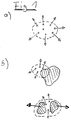
Fig. 1 zeigt schematisch die von den Stoßwellen induzierten Bewegungsvorgänge, die zur Ortung des Fokalbereichs dienen können. Der Fokalbereich ist jeweils durch eine gestrichelte Markierung umrandet und die Bewegungsrichtungen durch Pfeile dargestellt.
In Fig. 1a ist die Dynamik von Kavitationsblasen, die in einer Flüssigkeit innerhalb des Fokalbereichs der Stoßwellen entstehen, dargestellt. Die Kavitationsblasen wirken als bewegtes Ultraschallkontrastmedium und sind deshalb im Ultraschall-B-Bild sichtbar.
In Fig. 1b ist die Dynamik von Steinmaterial innerhalb des Fokalbereichs dargestellt. Große Steine (obere Abbildung) verhalten sich im wesentlichen immobil, so daß vor allem die in der umgebenden Flüssigkeit entstehenden Kavitationsblasen zur Ortung des Fokalbereichs dienen.1 shows schematically the movement processes induced by the shock waves, which can serve to locate the focal area. The focal area is surrounded by a dashed line and the directions of movement are shown by arrows.
1a shows the dynamics of cavitation bubbles that arise in a liquid within the focal region of the shock waves. The cavitation bubbles act as a moving ultrasound contrast medium and are therefore visible in the ultrasound B-image.
1b shows the dynamics of stone material within the focal area. Large stones (top illustration) behave essentially immobile, so that the cavitation bubbles that form in the surrounding liquid serve primarily to locate the focal area.
In Fig. 1b, untere Abbildung, ist die Dynamik von Steinfragmenten dargestellt. Hier sind sowohl die Bewegung der Steinfragmente als auch die in der umgebenden Flüssigkeit entstehenden Kavitationsblasen zur Ortung des Fokalbereichs geeignet.In Fig. 1b, lower figure, the dynamics of stone fragments is shown. Here both the movement of the stone fragments and the cavitation bubbles in the surrounding liquid are suitable for locating the focal area.
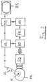
Fig. 2 zeigt das Blockschaltbild einer erfindungsgemäßen Vorrichtung. Im Patientenkörper PK befindet sich das zu therapierende Konkrement K. In der Stoßwellenquelle SQ werden Ultraschallstoßwellen erzeugt, fokussiert und auf das Konkrement K ausgerichtet. Ein Ultraschallscanner SC sendet Ultraschallwellen und empfängt deren Echos, die in der Ultraschallvorrichtung US zu einem Ultraschall-B-Bild des betrachteten Körperbereichs weiterverarbeitet werden. Das B-Bild wird in einer Vorrichtung BD zur Detektion der durch die Stoßwellen induzierten Bewegungsvorgänge weitergeleitet. Die Detektion erfolgt dort durch Segmentierung und Korrelation zweier aufeinanderfolgender, also zu verschiedenen Zeiten aufgenommener B-Bilder Bi, Bi+k mit k=> 1. Durch eine Triggereinheit TR wird die Bewegungsdetektion beschränkt auf ein Zeitfenster nach Auslösung der Stoßwellen in der Stoßwellenquelle SQ. In der Vorrichtung FK werden die berechneten Geschwindigkeitswerte farbkodiert, so daß der in den B-Bildern abgebildete Bereich des Patientenkörpers PK in ein Geschwindigkeitsbild gewandelt wird. Anschließend erfolgt in der Vorrichtung NV eine Nachverarbeitung des farbkodierten Bildes (z.B. Glättung, Interpolation).
In einer Mischstufe MS wird das farbkodierte Geschwindigkeitsbild mit dem Ultraschall-B-Bild überlagert und auf einem Bildschirm BS sichtbar gemacht.2 shows the block diagram of a device according to the invention. The concrement K to be treated is located in the patient's body PK . Ultrasonic shock waves are generated, focused and aligned with the concretion K in the shock wave source SQ . An ultrasound scanner SC sends ultrasound waves and receives their echoes, which are further processed in the ultrasound device US to form an ultrasound B-image of the area of the body under consideration. The B-image is passed on in a device BD for the detection of the movement processes induced by the shock waves. The detection takes place there by segmenting and correlating two successive B-images B i , B i + k with k => 1, ie taken at different times. A trigger unit TR limits the motion detection to a time window after the shock waves are triggered in the shock wave source SQ . The calculated speed values are color-coded in the device FK , so that the area of the patient's body PK shown in the B-pictures is converted into a speed picture. The color-coded image is then postprocessed in device NV (eg smoothing, interpolation).
In a mixing stage MS , the color-coded speed image is overlaid with the ultrasound B image and made visible on a screen BS .
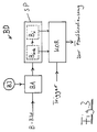
Fig. 3 zeigt das Blockschaltbild einer Ausführung der Vorrichtung BD zur Detektion der von dem Stoßwellen induzierten Bewegungsvorgängen. Im Bildspeicher SP, der z.B. als Schiebespeicher ausgelegt ist, werden zwei aufeinanderfolgende B-Bilder Bi,Bi+k, mit k >= 1, gespeichert. Mit der Vorrichtung BA kann der angenommene Fokalbereich, im folgenden auch ROI (Region-Of-Interest) genannt, innerhalb des B-Bildes über ein Benutzerinterface BI festgelegt werden, so daß nur innerhalb dieses ROI Bewegungsvorgänge detektiert werden.
Im Korrelator KOR werden die beiden ROI nach einem, z.B. quadratischen Raster in Bildsegmente geeigneter Größe aufgeteilt. Ein Segment umfaßt dabei in der Regel mehrere Bildpunkte (pixel). Anschließend werden die Korrelationskoeffizienten zwischen jeweils einem Segment im ersten Bild Bi und der Bildumgebung des entsprechenden Segments im Folgebild Bi+k berechnet. Grundlage für die Berechnung sind die Graustufenwerte der einzelnen Bildpunkte. Der Differenzvektor zwischen dem Segment im ersten Bild Bi und dem Bereich maximaler Korrelation im Folgebild wird zur Berechnung von Betrag und Geschwindigkeit des Bewegungsvektors verwendet. Aus dem Korrelationsprozeß hervorgehende, jedoch physikalisch unsinnige Schätzwerte können erkannt und herausgefiltert werden.
Die Gesamtheit der ermittelten zweidimensionalen Geschwindigkeitsvektoren werden bei der anschließenden Farbkodierung in ein Geschwindigkeitsbild gewandelt. Jedem Bildsegment ist dabei eine Farbe/Intensitäts-Kombination für Richtung und Betrag zugeordnet.
Durch die Triggereinheit TR wird die Bewegungsdetektion auf stoßwellenrelevante Zeiten beschränkt.
Gegenüber der Detektion der induzierten Bewegungsvorgänge nach dem Dopplerverfahren besitzt die erfindungsgemäße Vorrichtung den Vorteil der Erfassung von zweidimensionalen Geschwindigkeitskomponenten. Somit kann sowohl das B-Bild eines In-Line-Scanners wie auch eines Off-Axis-Scanners verwendet werden ohne Einbußen in der Detektion von Bewegungsvorgängen in einer etwaigen Vorzugsrichtung.FIG. 3 shows the block diagram of an embodiment of the device BD for detecting the movement processes induced by the shock waves. in the Image memory SP , which is designed, for example, as a sliding memory, two successive B-images B i , B i + k , with k> = 1, are stored. With the device BA , the assumed focal area, also referred to below as ROI (Region-Of-Interest), can be defined within the B-picture via a user interface BI , so that movement processes are only detected within this ROI.
In the KOR correlator, the two ROIs are divided into image segments of a suitable size according to a square grid, for example. A segment usually comprises several pixels. The correlation coefficients between each segment in the first image B i and the image environment of the corresponding segment in the subsequent image B i + k are then calculated. The calculation is based on the grayscale values of the individual pixels. The difference vector between the segment in the first image B i and the area of maximum correlation in the subsequent image is used to calculate the amount and speed of the motion vector. Estimates that result from the correlation process, but are physically nonsensical, can be recognized and filtered out.
The entirety of the two-dimensional speed vectors determined are converted into a speed image in the subsequent color coding. A color / intensity combination for direction and amount is assigned to each image segment.
The trigger unit TR limits movement detection to times relevant to shock waves.
Compared to the detection of the induced movement processes using the Doppler method, the device according to the invention has the advantage of detecting two-dimensional speed components. This means that both the B-scan of an in-line scanner and an off-axis scanner can be used can be used without any loss in the detection of movement processes in any preferred direction.
Claims (3)
- Device for determining the focal range of shockwaves generated in a shockwave source (SQ) relative to a concrement (K) located in the body (PK) of a living organism, comprising- ultrasound devices (SC, US) for generating ultrasound-B-images of an image area within the body (PK);- a device (BD) for detecting movement processes induced in the body (PK) by shockwaves;- a trigger unit (TR) to restrict movement detection to a specified time window after triggering of the shockwaves;- a device (FK) for generating a colour-coded velocity image of the image range; and- a device (MS) for superpositioning the colour-coded velocity image with an ultrasound-B-image;characterized in that the device (BD) for the detection of movement processes comprises an image store (SP) for storing two ultrasound-B-images (Bi, Bi+k) and a correlation device (KOR) wherein the two stored ultrasound-B-images (Bi, Bi+k) are divided into image segments and the image segments of the one ultrasound-B-image (Bi) are correlated with the surrounding of the respective segment in the other ultrasound-B-image (Bi+k).
- Device according to Claim 1, characterized in that the device (BD) for detection of movement processes incorporates an additional device (BA) for determining a region of interest (assumed focal range) within an ultrasound-B-image (Bi, Bi+k), so that movement processes are only detected within the region of interest.
- Device according to one of the above claims, characterized in that a device (NV) is provided for subsequent processing of colour-coded velocity images (for example by smoothing and interpolation).
Applications Claiming Priority (2)
| Application Number | Priority Date | Filing Date | Title |
|---|---|---|---|
| DE4113697A DE4113697A1 (en) | 1991-04-26 | 1991-04-26 | FOCAL AREA DEVICE FOR LITHOTRIPSY |
| DE4113697 | 1991-04-26 |
Publications (2)
| Publication Number | Publication Date |
|---|---|
| EP0511506A1 EP0511506A1 (en) | 1992-11-04 |
| EP0511506B1 true EP0511506B1 (en) | 1996-10-09 |
Family
ID=6430438
Family Applications (1)
| Application Number | Title | Priority Date | Filing Date |
|---|---|---|---|
| EP92105570A Expired - Lifetime EP0511506B1 (en) | 1991-04-26 | 1992-04-01 | Device for location of the focal region in lithotripsy |
Country Status (4)
| Country | Link |
|---|---|
| US (1) | US5287856A (en) |
| EP (1) | EP0511506B1 (en) |
| JP (1) | JP2530796B2 (en) |
| DE (2) | DE4113697A1 (en) |
Cited By (1)
| Publication number | Priority date | Publication date | Assignee | Title |
|---|---|---|---|---|
| US9060915B2 (en) | 2004-12-15 | 2015-06-23 | Dornier MedTech Systems, GmbH | Methods for improving cell therapy and tissue regeneration in patients with cardiovascular diseases by means of shockwaves |
Families Citing this family (19)
| Publication number | Priority date | Publication date | Assignee | Title |
|---|---|---|---|---|
| DE4241161C2 (en) * | 1992-12-07 | 1995-04-13 | Siemens Ag | Acoustic therapy facility |
| DE4446192A1 (en) * | 1994-12-23 | 1996-07-04 | Wolf Gmbh Richard | Procedure for accurate hit control of treatment |
| US7189209B1 (en) | 1996-03-29 | 2007-03-13 | Sanuwave, Inc. | Method for using acoustic shock waves in the treatment of a diabetic foot ulcer or a pressure sore |
| US6390995B1 (en) | 1997-02-12 | 2002-05-21 | Healthtronics Surgical Services, Inc. | Method for using acoustic shock waves in the treatment of medical conditions |
| US7078388B2 (en) * | 2000-01-21 | 2006-07-18 | Merial | DNA vaccines for farm animals, in particular bovines and porcines |
| DE10100974B4 (en) | 2001-01-11 | 2004-07-08 | Hmt High Medical Technologies Ag | Device for generating shock waves |
| DE10102317A1 (en) * | 2001-01-19 | 2002-08-14 | Hmt Ag | Method and device for applying pressure waves to the body of a living being |
| DE10125936A1 (en) * | 2001-05-23 | 2003-01-02 | Hmt Ag | Medical device |
| DE10158519B4 (en) * | 2001-11-29 | 2005-01-13 | Dornier Medtech Holding International Gmbh | Shock and shock wave therapy device |
| DE10234144A1 (en) | 2002-07-26 | 2004-02-05 | Dornier Medtech Gmbh | lithotripter |
| DE102005017724A1 (en) * | 2005-04-15 | 2006-11-09 | Ast Gmbh | Focusing device for a device for generating shockwaves |
| US8219940B2 (en) * | 2005-07-06 | 2012-07-10 | Semiconductor Insights Inc. | Method and apparatus for removing dummy features from a data structure |
| DE102005037043C5 (en) | 2005-08-05 | 2017-12-14 | Dornier Medtech Systems Gmbh | Shock wave therapy device with image acquisition |
| DE102006002273A1 (en) * | 2006-01-17 | 2007-07-26 | Dornier Medtech Systems Gmbh | treatment facility |
| US7610079B2 (en) * | 2006-07-25 | 2009-10-27 | Ast Gmbh | Shock wave imaging system |
| DE102006050781A1 (en) * | 2006-10-27 | 2008-04-30 | Ast Gmbh | Device for the spatial positioning of a device |
| WO2009027920A2 (en) * | 2007-08-31 | 2009-03-05 | Koninklijke Philips Electronics N.V. | An ultrasound device for detecting presence or absence of cavitation events |
| US20130274590A1 (en) * | 2012-04-17 | 2013-10-17 | Vincent Auboiroux | Method and apparatus for generating a signal indicative of motion of a subject in a magnetic resonance apparatus |
| US10402513B2 (en) * | 2017-03-31 | 2019-09-03 | Lite-Med Inc. | Calculus targeting method and system |
Family Cites Families (10)
| Publication number | Priority date | Publication date | Assignee | Title |
|---|---|---|---|---|
| US4580894A (en) * | 1983-06-30 | 1986-04-08 | Itek Corporation | Apparatus for measuring velocity of a moving image or object |
| DE3517934A1 (en) * | 1985-05-18 | 1986-11-20 | Märkisches Werk Doyce GmbH, 5884 Halver | Method of crushing renal calculi, and a system for performing the method |
| DE3782579D1 (en) * | 1986-07-18 | 1992-12-17 | Siemens Ag | DEVICE FOR CRUSHING CONCREMES. |
| US5065741A (en) * | 1987-04-16 | 1991-11-19 | Olympus Optical Co. Ltd. | Extracoporeal ultrasonic lithotripter with a variable focus |
| DE3739230A1 (en) * | 1987-11-19 | 1989-06-01 | Siemens Ag | MEDICAL EXAMINATION SYSTEM |
| US4962754A (en) * | 1988-01-13 | 1990-10-16 | Kabushiki Kaisha Toshiba | Shock wave treatment apparatus |
| FR2629997B1 (en) * | 1988-04-19 | 1990-08-17 | Labo Electronique Physique | CORRELATION MEASUREMENT DEVICE FOR SPEED OF MOVING ORGANS AND BLOOD FLOWS |
| DE3913023C2 (en) * | 1988-04-22 | 1993-10-14 | Toshiba Kawasaki Kk | Shatter wave treatment device |
| EP0548048B1 (en) * | 1988-10-26 | 1996-02-14 | Kabushiki Kaisha Toshiba | Shock wave treatment apparatus |
| JP2534764B2 (en) * | 1989-01-10 | 1996-09-18 | 株式会社東芝 | Shock wave therapy device |
-
1991
- 1991-04-26 DE DE4113697A patent/DE4113697A1/en active Granted
-
1992
- 1992-04-01 DE DE59207310T patent/DE59207310D1/en not_active Expired - Fee Related
- 1992-04-01 EP EP92105570A patent/EP0511506B1/en not_active Expired - Lifetime
- 1992-04-24 JP JP4106924A patent/JP2530796B2/en not_active Expired - Lifetime
- 1992-04-27 US US07/874,761 patent/US5287856A/en not_active Expired - Lifetime
Cited By (1)
| Publication number | Priority date | Publication date | Assignee | Title |
|---|---|---|---|---|
| US9060915B2 (en) | 2004-12-15 | 2015-06-23 | Dornier MedTech Systems, GmbH | Methods for improving cell therapy and tissue regeneration in patients with cardiovascular diseases by means of shockwaves |
Also Published As
| Publication number | Publication date |
|---|---|
| JP2530796B2 (en) | 1996-09-04 |
| DE59207310D1 (en) | 1996-11-14 |
| DE4113697C2 (en) | 1993-09-09 |
| US5287856A (en) | 1994-02-22 |
| DE4113697A1 (en) | 1992-11-05 |
| JPH0622974A (en) | 1994-02-01 |
| EP0511506A1 (en) | 1992-11-04 |
Similar Documents
| Publication | Publication Date | Title |
|---|---|---|
| EP0511506B1 (en) | Device for location of the focal region in lithotripsy | |
| DE4125950C1 (en) | ||
| EP0168559B1 (en) | Device for detecting and positioning concrements | |
| DE3844672C2 (en) | Therapy appts. with ultrasonic treatment transmitter | |
| DE3743883C2 (en) | Medical ultrasound treatment device | |
| DE69732511T2 (en) | Processing method for signals of objects with moving parts and echography apparatus therefor | |
| DE60028952T2 (en) | METHOD AND DEVICE FOR GENERATING PICTURES THROUGH THE USE OF SHEARS | |
| CN107753062B (en) | Transcranial ultrasonic cerebrovascular angiography super-resolution imaging method based on Markov chain Monte Carlo multi-target tracking | |
| DE3900893C2 (en) | ||
| DE60130598T2 (en) | Method and apparatus for automatically adjusting a scanning gate in pulse Doppler ultrasound imaging | |
| EP0372174B1 (en) | Lithotriptor | |
| EP1749488B1 (en) | Shockwave therapy apparatus with imaging | |
| DE10322157A1 (en) | Display device for subtraction imaging processes | |
| DE4309596A1 (en) | Process for imaging using echo signals | |
| DE3617032C2 (en) | Lithotripsy device with extracorporeal shock wave generator | |
| DE19548000C1 (en) | Device for locating calculus in a patient's body | |
| DE19754085A1 (en) | A sonographic elastography system | |
| DE2329387A1 (en) | PROCEDURE AND EQUIPMENT FOR ULTRASONIC TESTING OF AN OBJECT | |
| EP2078503B1 (en) | Navigation for focussed pressure wave treatment | |
| US8668648B2 (en) | Contrast agent destruction effectiveness determination for medical diagnostic ultrasound imaging | |
| DE102005031125A1 (en) | Method and lithotripsy apparatus for destroying a calculus in a patient | |
| Lee et al. | FUS-net: u-Net-based FUS interference filtering | |
| WO2011089160A1 (en) | Device for determining vertebra spacing in the spinal column | |
| DE102005039178B4 (en) | Device and method for determining the Ankoppelgüte between coupling bellows and patients in a device for extracorporeal treatment with acoustic shock waves | |
| Chan | Two approaches to motion analysis of the ultrasound image sequence of carotid atheromatous plaque |
Legal Events
| Date | Code | Title | Description |
|---|---|---|---|
| PUAI | Public reference made under article 153(3) epc to a published international application that has entered the european phase |
Free format text: ORIGINAL CODE: 0009012 |
|
| AK | Designated contracting states |
Kind code of ref document: A1 Designated state(s): CH DE ES FR GB IT LI NL |
|
| 17P | Request for examination filed |
Effective date: 19921204 |
|
| 17Q | First examination report despatched |
Effective date: 19950309 |
|
| GRAH | Despatch of communication of intention to grant a patent |
Free format text: ORIGINAL CODE: EPIDOS IGRA |
|
| RBV | Designated contracting states (corrected) |
Designated state(s): DE |
|
| GRAH | Despatch of communication of intention to grant a patent |
Free format text: ORIGINAL CODE: EPIDOS IGRA |
|
| GRAA | (expected) grant |
Free format text: ORIGINAL CODE: 0009210 |
|
| AK | Designated contracting states |
Kind code of ref document: B1 Designated state(s): DE |
|
| REF | Corresponds to: |
Ref document number: 59207310 Country of ref document: DE Date of ref document: 19961114 |
|
| PLBE | No opposition filed within time limit |
Free format text: ORIGINAL CODE: 0009261 |
|
| STAA | Information on the status of an ep patent application or granted ep patent |
Free format text: STATUS: NO OPPOSITION FILED WITHIN TIME LIMIT |
|
| 26N | No opposition filed | ||
| PGFP | Annual fee paid to national office [announced via postgrant information from national office to epo] |
Ref country code: DE Payment date: 20070530 Year of fee payment: 16 |
|
| PG25 | Lapsed in a contracting state [announced via postgrant information from national office to epo] |
Ref country code: DE Free format text: LAPSE BECAUSE OF NON-PAYMENT OF DUE FEES Effective date: 20081101 |