EP0511244B1 - Fraese zur resektion von knochen - Google Patents
Fraese zur resektion von knochen Download PDFInfo
- Publication number
- EP0511244B1 EP0511244B1 EP91902035A EP91902035A EP0511244B1 EP 0511244 B1 EP0511244 B1 EP 0511244B1 EP 91902035 A EP91902035 A EP 91902035A EP 91902035 A EP91902035 A EP 91902035A EP 0511244 B1 EP0511244 B1 EP 0511244B1
- Authority
- EP
- European Patent Office
- Prior art keywords
- milling cutter
- bone
- platform
- femoral
- tibial
- Prior art date
- Legal status (The legal status is an assumption and is not a legal conclusion. Google has not performed a legal analysis and makes no representation as to the accuracy of the status listed.)
- Expired - Lifetime
Links
Images


Classifications
-
- A—HUMAN NECESSITIES
- A61—MEDICAL OR VETERINARY SCIENCE; HYGIENE
- A61B—DIAGNOSIS; SURGERY; IDENTIFICATION
- A61B17/00—Surgical instruments, devices or methods, e.g. tourniquets
- A61B17/16—Bone cutting, breaking or removal means other than saws, e.g. Osteoclasts; Drills or chisels for bones; Trepans
- A61B17/1662—Bone cutting, breaking or removal means other than saws, e.g. Osteoclasts; Drills or chisels for bones; Trepans for particular parts of the body
- A61B17/1675—Bone cutting, breaking or removal means other than saws, e.g. Osteoclasts; Drills or chisels for bones; Trepans for particular parts of the body for the knee
-
- A—HUMAN NECESSITIES
- A61—MEDICAL OR VETERINARY SCIENCE; HYGIENE
- A61B—DIAGNOSIS; SURGERY; IDENTIFICATION
- A61B17/00—Surgical instruments, devices or methods, e.g. tourniquets
- A61B17/16—Bone cutting, breaking or removal means other than saws, e.g. Osteoclasts; Drills or chisels for bones; Trepans
- A61B17/1613—Component parts
- A61B17/1622—Drill handpieces
- A61B17/1624—Drive mechanisms therefor
-
- A—HUMAN NECESSITIES
- A61—MEDICAL OR VETERINARY SCIENCE; HYGIENE
- A61B—DIAGNOSIS; SURGERY; IDENTIFICATION
- A61B17/00—Surgical instruments, devices or methods, e.g. tourniquets
- A61B17/16—Bone cutting, breaking or removal means other than saws, e.g. Osteoclasts; Drills or chisels for bones; Trepans
- A61B17/17—Guides or aligning means for drills, mills, pins or wires
- A61B17/1739—Guides or aligning means for drills, mills, pins or wires specially adapted for particular parts of the body
- A61B17/1764—Guides or aligning means for drills, mills, pins or wires specially adapted for particular parts of the body for the knee
-
- A—HUMAN NECESSITIES
- A61—MEDICAL OR VETERINARY SCIENCE; HYGIENE
- A61F—FILTERS IMPLANTABLE INTO BLOOD VESSELS; PROSTHESES; DEVICES PROVIDING PATENCY TO, OR PREVENTING COLLAPSING OF, TUBULAR STRUCTURES OF THE BODY, e.g. STENTS; ORTHOPAEDIC, NURSING OR CONTRACEPTIVE DEVICES; FOMENTATION; TREATMENT OR PROTECTION OF EYES OR EARS; BANDAGES, DRESSINGS OR ABSORBENT PADS; FIRST-AID KITS
- A61F2/00—Filters implantable into blood vessels; Prostheses, i.e. artificial substitutes or replacements for parts of the body; Appliances for connecting them with the body; Devices providing patency to, or preventing collapsing of, tubular structures of the body, e.g. stents
- A61F2/02—Prostheses implantable into the body
- A61F2/30—Joints
- A61F2/38—Joints for elbows or knees
-
- A—HUMAN NECESSITIES
- A61—MEDICAL OR VETERINARY SCIENCE; HYGIENE
- A61B—DIAGNOSIS; SURGERY; IDENTIFICATION
- A61B17/00—Surgical instruments, devices or methods, e.g. tourniquets
- A61B17/14—Surgical saws ; Accessories therefor
- A61B17/15—Guides therefor
-
- A—HUMAN NECESSITIES
- A61—MEDICAL OR VETERINARY SCIENCE; HYGIENE
- A61B—DIAGNOSIS; SURGERY; IDENTIFICATION
- A61B17/00—Surgical instruments, devices or methods, e.g. tourniquets
- A61B17/16—Bone cutting, breaking or removal means other than saws, e.g. Osteoclasts; Drills or chisels for bones; Trepans
- A61B17/1613—Component parts
- A61B17/1615—Drill bits, i.e. rotating tools extending from a handpiece to contact the worked material
-
- A—HUMAN NECESSITIES
- A61—MEDICAL OR VETERINARY SCIENCE; HYGIENE
- A61B—DIAGNOSIS; SURGERY; IDENTIFICATION
- A61B17/00—Surgical instruments, devices or methods, e.g. tourniquets
- A61B17/32—Surgical cutting instruments
- A61B17/320016—Endoscopic cutting instruments, e.g. arthroscopes, resectoscopes
-
- A—HUMAN NECESSITIES
- A61—MEDICAL OR VETERINARY SCIENCE; HYGIENE
- A61B—DIAGNOSIS; SURGERY; IDENTIFICATION
- A61B17/00—Surgical instruments, devices or methods, e.g. tourniquets
- A61B17/56—Surgical instruments or methods for treatment of bones or joints; Devices specially adapted therefor
- A61B17/58—Surgical instruments or methods for treatment of bones or joints; Devices specially adapted therefor for osteosynthesis, e.g. bone plates, screws, setting implements or the like
- A61B17/68—Internal fixation devices, including fasteners and spinal fixators, even if a part thereof projects from the skin
- A61B17/70—Spinal positioners or stabilisers ; Bone stabilisers comprising fluid filler in an implant
- A61B17/7097—Stabilisers comprising fluid filler in an implant, e.g. balloon; devices for inserting or filling such implants
- A61B17/7098—Stabilisers comprising fluid filler in an implant, e.g. balloon; devices for inserting or filling such implants wherein the implant is permeable or has openings, e.g. fenestrated screw
-
- A—HUMAN NECESSITIES
- A61—MEDICAL OR VETERINARY SCIENCE; HYGIENE
- A61B—DIAGNOSIS; SURGERY; IDENTIFICATION
- A61B17/00—Surgical instruments, devices or methods, e.g. tourniquets
- A61B17/56—Surgical instruments or methods for treatment of bones or joints; Devices specially adapted therefor
- A61B17/58—Surgical instruments or methods for treatment of bones or joints; Devices specially adapted therefor for osteosynthesis, e.g. bone plates, screws, setting implements or the like
- A61B17/88—Osteosynthesis instruments; Methods or means for implanting or extracting internal or external fixation devices
- A61B17/8802—Equipment for handling bone cement or other fluid fillers
- A61B17/8805—Equipment for handling bone cement or other fluid fillers for introducing fluid filler into bone or extracting it
- A61B17/8822—Equipment for handling bone cement or other fluid fillers for introducing fluid filler into bone or extracting it characterised by means facilitating expulsion of fluid from the introducer, e.g. a screw pump plunger, hydraulic force transmissions, application of vibrations or a vacuum
-
- A—HUMAN NECESSITIES
- A61—MEDICAL OR VETERINARY SCIENCE; HYGIENE
- A61B—DIAGNOSIS; SURGERY; IDENTIFICATION
- A61B17/00—Surgical instruments, devices or methods, e.g. tourniquets
- A61B2017/00535—Surgical instruments, devices or methods, e.g. tourniquets pneumatically or hydraulically operated
- A61B2017/00544—Surgical instruments, devices or methods, e.g. tourniquets pneumatically or hydraulically operated pneumatically
-
- A—HUMAN NECESSITIES
- A61—MEDICAL OR VETERINARY SCIENCE; HYGIENE
- A61B—DIAGNOSIS; SURGERY; IDENTIFICATION
- A61B17/00—Surgical instruments, devices or methods, e.g. tourniquets
- A61B17/16—Bone cutting, breaking or removal means other than saws, e.g. Osteoclasts; Drills or chisels for bones; Trepans
- A61B2017/1602—Mills
-
- A—HUMAN NECESSITIES
- A61—MEDICAL OR VETERINARY SCIENCE; HYGIENE
- A61M—DEVICES FOR INTRODUCING MEDIA INTO, OR ONTO, THE BODY; DEVICES FOR TRANSDUCING BODY MEDIA OR FOR TAKING MEDIA FROM THE BODY; DEVICES FOR PRODUCING OR ENDING SLEEP OR STUPOR
- A61M1/00—Suction or pumping devices for medical purposes; Devices for carrying-off, for treatment of, or for carrying-over, body-liquids; Drainage systems
- A61M1/84—Drainage tubes; Aspiration tips
-
- A—HUMAN NECESSITIES
- A61—MEDICAL OR VETERINARY SCIENCE; HYGIENE
- A61M—DEVICES FOR INTRODUCING MEDIA INTO, OR ONTO, THE BODY; DEVICES FOR TRANSDUCING BODY MEDIA OR FOR TAKING MEDIA FROM THE BODY; DEVICES FOR PRODUCING OR ENDING SLEEP OR STUPOR
- A61M2205/00—General characteristics of the apparatus
- A61M2205/10—General characteristics of the apparatus with powered movement mechanisms
- A61M2205/103—General characteristics of the apparatus with powered movement mechanisms rotating
-
- Y—GENERAL TAGGING OF NEW TECHNOLOGICAL DEVELOPMENTS; GENERAL TAGGING OF CROSS-SECTIONAL TECHNOLOGIES SPANNING OVER SEVERAL SECTIONS OF THE IPC; TECHNICAL SUBJECTS COVERED BY FORMER USPC CROSS-REFERENCE ART COLLECTIONS [XRACs] AND DIGESTS
- Y10—TECHNICAL SUBJECTS COVERED BY FORMER USPC
- Y10S—TECHNICAL SUBJECTS COVERED BY FORMER USPC CROSS-REFERENCE ART COLLECTIONS [XRACs] AND DIGESTS
- Y10S623/00—Prosthesis, i.e. artificial body members, parts thereof, or aids and accessories therefor
- Y10S623/915—Method or apparatus for preparing biological material
- Y10S623/919—Bone
-
- Y—GENERAL TAGGING OF NEW TECHNOLOGICAL DEVELOPMENTS; GENERAL TAGGING OF CROSS-SECTIONAL TECHNOLOGIES SPANNING OVER SEVERAL SECTIONS OF THE IPC; TECHNICAL SUBJECTS COVERED BY FORMER USPC CROSS-REFERENCE ART COLLECTIONS [XRACs] AND DIGESTS
- Y10—TECHNICAL SUBJECTS COVERED BY FORMER USPC
- Y10T—TECHNICAL SUBJECTS COVERED BY FORMER US CLASSIFICATION
- Y10T407/00—Cutters, for shaping
- Y10T407/19—Rotary cutting tool
- Y10T407/1946—Face or end mill
- Y10T407/1948—Face or end mill with cutting edge entirely across end of tool [e.g., router bit, end mill, etc.]
Definitions
- the present invention pertains to resection of bones for receiving prosthetic components of particular use in knee replacement procedures and, more specifically, to apparatus for arthroscopic knee replacement.
- Prosthetic replacement of the knee is a procedure of substantial importance to recreate the knee joint with a pain-free functional arc of motion and antero-posterior and varus-valgus stability.
- the knee is, basically, formed of medial and lateral tibia] plateaus, medial and lateral femoral condyles and menisci between the tibial plateaus and the femoral condyles along with the patella which covers the anterior surface of the knee, and prosthetic replacement of the knee as described herein relates to the tibial plateaus, the femoral condyles and the menisci.
- prostheses are presently available, as described in detail in Replacement of the Knee , Laskin, Denham and Apley, Springer-Verlag Berlin Heidelberg, 1984, and are commonly grouped as partial or unicompartmental replacements of the medial or lateral portion of the tibio-femoral joint, surface replacements to prevent contact between worn surfaces and jack the joint surfaces apart, linked joints and fixed hinge joints.
- the type of prothesis employed must be matched to the needs of the patient. By selecting the proper prothesis, antero-posterior and varus-valgus stability can be achieved by prosthetic replacement coupled with bone surfacing or resection.
- Open surgery required for prior art prosthetic replacements typically necessitates a long incision, on the order of 25,4 cm (ten inches), along the anterior midline of the knee from above the patella to below the tibial tubercle followed by a deep dissection around the medial border of the patella and along the patellar ligament to the tibial tubercle with detachment of the medial third of the quadriceps attachment from the upper border of the patella.
- the tendinous margin is then pulled downwards and medially while the patella is pulled downwards and laterally.
- the quadriceps tendon is then split, and the patella is displaced laterally and everted. While the above is a simplified explanation of open knee surgery, it serves to explain the substantial trauma and recovery time associated therewith.
- Another object of the present invention is to accurately resect tibial plateau and femoral condyle planar surfaces relative to each other such that the tibial plateau and femoral condyle surfaces are constrained to be disposed in planes perpendicular to a substantially vertical reference plane.
- a further object of the present invention is to cement a prosthesis to a tissue surface after the prosthesis is accurately placed on the tissue surface.
- An additional object of the present invention is to perform a least invasive prosthetic knee replacement with the use of arthroscopy and requiring only arthroscopic size portals.
- the present invention has another object in the performing of all procedures for a prosthetic knee replacement, including surface preparation, fitting and implanting, arthroscopically through small portals enlarged only for insertion of the final components.
- Yet an additional object of the present invention is to arthroscopically resect tibial plateau an femoral condyle surfaces using existing surface anatomy as a reference point.
- a further object of the present invention is to improve the mechanical bond created by cement between a prosthesis and a bone surface by applying suction to the bone to draw the cement into the bone.
- Some of the advantages of the present invention over prior art prosthetic knee replacements are that, by using arthroscopic surgical techniques and small portals in place of the long incisions required for open knee procedures, trauma and recovery time are substantially reduced, alignment of the tibial and femoral prosthesis components is assured by fixing the femoral cutting jig with reference to the tibial cutting jig and, therefore, resecting the femoral condyle with reference to the resected tibial plateau, the knee is restored to a normal, healthy condition by resecting the tibial plateau and the tibial condyle using the existing surface anatomy as a reference point, and prostheses are cemented after accurate positioning of the prostheses on the bone.
- a rotatable milling cutter is defined in claim 1.
- apparatus for resecting bone and which includes the above milling cutter is defined in claim 2.
- prosthetic knee replacement in accordance with the present invention requires only small portals to perform all bone and tissue preparation procedures as well as implanting the prosthetic tibial and femoral components and cementing the components in place. Accordingly, prosthetic knee replacement in accordance with the present invention can be performed with the use of arthroscopic surgical procedures.
- portal is meant a puncture or stab wound of the type made by a plunge cut with a scalpel or trocar and of the type commonly used in conventional arthoscopic procedures, the size of the portal being just large enough to allow insertion of instruments.
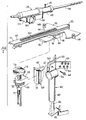
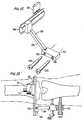
- a tibial jig 40 in accordance with the present invention is illustrated in Fig. 1 and includes a lower V-block 42 adapted to rest just above the malleoli at the ankle and an upper V-block 44 adapted to be secured to the tibia just below the tibial tubercle.
- Lower V-block 42 is connected to a rod 46 telescopingly received within a tube 48 connected to upper V-block 44 which is formed of a pair of angled members having a plurality of holes 50 therein to receive screws 52 extending therethrough and into the tibia to securely mount the tibial jig thereon.
- a rod 46 telescopingly received within a tube 48
- upper V-block 44 which is formed of a pair of angled members having a plurality of holes 50 therein to receive screws 52 extending therethrough and into the tibia to securely mount the tibial jig thereon.
- tube 48 has spaced arms 54 and 56 terminating at the angled members of upper V-block 44, and an angular adjustment member 58 has a tongue 60 disposed between members 54 and 56 with a hole 62 therein for receiving an adjustment screw 64 extending through corresponding holes in members 54 and 56.
- the angular adjustment member 58 can be pivoted about screw 64 to a desired position and the screw tightened to hold the angular adjustment member in place.
- a longitudinal adjustment block 66 has a dovetail slot 68 therein to receive a dovetail 70 on member 58, and a longitudinal adjustment screw 72 is held in a non-rotating manner in block 66 and carries a head 74 having a dovetail slot 76 therein.
- Block 66 has spaced arms between which is mounted a thumbwheel 76 threadedly engaging adjustment screw 72 such that rotation of thumbwheel 76 causes longitudinal axial movement of the screw and the head.
- a block 80 has a dovetail 82 received in slot 76 and mounts a cutter platform generally indicated at 84.
- a longitudinal or depth of cut gauge 86 is mounted on an extension 88 of block 66 and carries indicia 90 allowing registration with an index mark on screw 72 to indicate the depth of a cut being made, as will be explained in more detail hereinafter.
- the gauge has a zero center mark with indicia extending in either direction therefrom in millimeter graduations.
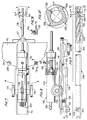
- the platform 84 includes a semi-circular plate 92 having a curved peripheral edge 94 and a dovetail 96 slidably received in a dovetail slot 98 in block 80 to permit movement of the platform in a lateral direction perpendicular to the longitudinal movement of screw 72.
- a linear slide member 100 has a distal end 102 pivotally mounted centrally on plate 92 and carries a toothed rack 104 longitudinally thereon.
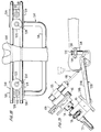
- the slide member 100 extends substantially beyond the peripheral edge 94 of plate 92 and carries on its back side a clamp assembly including a lever 106 pivotally mounted on ears 108 secured to the slide member, the lever 106 having a clamping end 110 and an operating end 112 as best shown in Fig. 8.
- a trigger like member 114 is pivotally mounted on a lug 116 extending from the slide member and has a flat portion engaging the operating end 112 of lever 106 which is biased against the trigger by means of a compression spring 118. Accordingly, when trigger 114 is moved toward the slide member (rotated clock-wise looking at Fig. 8) the operating end 112 of lever 106 is moved toward the slide member causing the clamping end 110 to move away from the peripheral edge 94 of plate 92 thereby allowing pivotal movement of the slide member relative to the plate. When the trigger 114 is released, the spring 118 returns the clamping end 110 to engagement with the plate to hold the slide member in the selected pivotal position.
- the slide member has an elongated dovetail 121 received in a slot 122 in a housing 124 of a cutter module generally indicated at 126.
- a pinion 128 having teeth for engaging rack 104 is mounted on an axle journaled through housing 124 to terminate at handwheels 132 on either side of the housing.
- a pneumatic motor 134 has a proximal end receiving drive and exhaust conduits 136 and a distal end engaging the shaft of a milling cutter 138 as best shown in Fig. 8.
- the motor is driven by pressurized fluid, such as nitrogen or air; and, when the drive fluid is provided at 7 ⁇ 10 5 N/m 2 (100 psi), the motor speed and torque are 4000 rpm and 560 Nm (50 oz-inch), respectively.
- a chamber 140 is formed around the drive coupling and has a port 142 for connection to a source of suction, the proximal end of the milling cutter 138 having a hole 144 therein for communicating with the chamber and the milling cutter 138 being rotatably supported at the distal end of the chamber by suitable bearing and journal structure.
- Stops 146 and 148 are movably secured to the peripheral edge 94 of plate 92 on opposite sides of slide member 100; and, as shown in Fig. 7a, are formed of set screws 150 for engaging the plate 92.
- the milling cutter 138 includes a shaft having a proximal end 152 for engaging a locking collet assembly in chamber 140 to be driven by the pneumatic motor, the shaft being hollow to establish communication between hole 144 in the proximal end thereof and holes 154 disposed in the distal portion thereof.
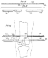
- the distal portion of the milling cutter includes a body 156 having a plurality of helical cutting edges 158 extending therealong, and at least one hole 154 is disposed between each pair of body cutting edges 158. As shown in Fig. 10, four equally spaced cutting edges are disposed on the fluted body 156, and holes 154 communicate with a passage 160 formed by the hollow shaft of the milling cutter.
- Cutting edges 162 are disposed at the distal end of the milling cutter in a plane extending transverse to the longitudinal axis of the milling cutter, and each of the body cutting edges 158 extends from one of the distal end cutting edges 162.
- the milling cutter preferably has a diameter of 7mm and the body cutting edges preferably have substantially radial leading edges.
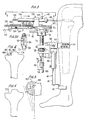
- tibial jig 40 is secured to the tibia by screws 52 extending through V-block 44 and into the tibia with the upper and lower V-blocks disposed just below the tibial tubercle and just above the malleoli at the ankle, respectively, with a set screw 163 provided to maintain the position of telescoping members 46 and 48.
- a portal 164 is formed in the knee for insertion of an arthroscope 166 for viewing of the knee and the surgical procedure, while a portal 168 is formed in the tissue adjacent the tibial plateau, Fig. 1 illustrating the portal 168 for use in resecting the medial tibial plateau of the left leg.
- the stylus module 176 includes a housing having a dovetail slot for receiving the dovetail 120 of the slide member and mounts a stylus 172 having four equally spaced positions controlled by detents, not shown, within the housing.
- the stylus has a curved radially extending tip 174 that can be positioned via the detents to extend up, down or to either side.
- the radial extension of the stylus 174 is preferably equal to the radius of the milling cutter, e.g., 3.5mm, and the housing of the stylus module positions the stylus at the same position at which the milling cutter is positioned when the cutter module is received on the slide member.
- angular adjustment block 58 is pivoted about screw 64 to align the platform with the natural tilt of the tibial plateau as sensed by the stylus, the natural tilt being normally between 3° and 10° posteriorly.
- the stylus is rotated 90° such that the tip 174 is turned to the right, and the tip of the stylus is moved by sliding the plate 92 in block 80 until the tip of the stylus contacts the tibial eminence 176 as illustrated in Fig. 27.
- a screw not shown, is tightened to secure the lateral position of the platform.
- the slide member 100 is centrally positioned on the plate 92 during this procedure, and the stop 148 is moved to abut the slide member 100 to prevent pivotal movement of the slide member and the milling cutter mill clockwise looking at Fig. 7.
- the tip 174 of the stylus With the tip 174 of the stylus turned down, the lowest point of contact of the tip on the tibial plateau is located; and, with the stylus at this contact point, thumbwheel 78 is locked in place to control the position of the resection to be performed, it being noted that, due to the dimensional relationship between the cutter module and the stylus module, the milling cutter will be aligned with the lowest point on the tibial plateau. As shown in dashed lines in Fig.
- the anterior portion of the meniscus or cartilage has been removed by normal arthroscopic techniques leaving a posterior segment indicated at 178 such that during the resection procedure, the posterior portion of the meniscus provides a cushion to provide the surgeon with an indication of the location of the posterior edge of the tibial plateau.
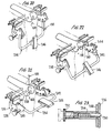
- the stylus module is removed and the cutter module is placed thereon as illustrated in Fig. 3; and, since angular, lateral and longitudinal adjustments have already been made and set in place, only linear and pivotal movements of the milling cutter can be made and such movements can be made only in a single plane.
- initial forward movement of the milling cutter produces a longitudinal plunge cut along the tibial eminence 176 to produce a trough across the tibial plateau as indicated at 180, it being noted that the milling cutter cuts on its distal end as well as along the fluted body thereof.
- the trigger 114 is released allowing pivotal movement of the slide member slightly; and, after the trigger is released to clamp the slide member in position, a second longitudinal cut is made by linear movement of the milling cutter as indicated at 182. This procedure is repeated until the surface of the tibial plateau is covered with troughs having ridges 184 therebetween.
- the trigger 114 is now depressed to release the slide member; and, with the milling cutter disposed over the tibial plateau, the milling cutter is pivoted back and forth to sweep the milling cutter over the tibial plateau removing the ridges, the sweeping movement being substantially transverse to the longitudinal movements of the milling cutter to form the troughs.
- suction is applied to port 142 such that bone chips are evacuated via holes 154 and passage 160 through the hollow milling cutter. The suction also serves to cool the surgical site and prevent cavitation.
- the cutter module is removed from the platform, and the platform is removed from block 80.
- An alignment bridge 186 as illustrated in Fig. 12, is then coupled with block 80 as illustrated in Figs. 11 and 13, it being noted that block 80 remains fixed relative to the tibia and, therefore, the resected planar tibial plateau.
- the alignment bridge 186 includes a dovetail slide 188 received in the slot 98 in block 80, and an arm 190 extends at an angle of 45° between slide 188 and a drill guide 192 having parallel bores 194 and 196 therethrough. Accordingly, the bores 194 and 196 will be disposed in a plane transverse to the plane of the resected tibial plateau.
- inserts 198 and 200 are passed through bores 194 and 196, respectively, to provide elongated guides for drilling parallel bores through the femur.
- the bores are drilled through the femur using conventional orthopedic techniques; and, after the bores are drilled through the femur, threaded rods 204 are passed through each bore as illustrated in Fig. 14.
- one of the threaded rods 204 is preferably hollow having a passage 206 therethrough providing communication between its end and holes 208 centrally located therein.
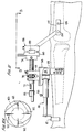
- Threaded sleeves 210 are disposed on the outer ends of each rod in threaded engagement with the rods while loosely sliding sleeves 212 are disposed between sleeves 210 and the femur, the sleeves being illustrated in Fig. 16 and shown in position relative to the femur in Fig. 14. With the sleeves tightened in place and the rods passing through the epicondylar region of the femur, a support for resecting the femoral condyle is established relative to the resected tibial plateau since the rods are disposed in a plane perpendicular to the planar tibial plateau.
- a femoral support base 214 is rigidly attached to the rods to prevent any deflection or twisting of the rods.
- the femoral support base 214 includes a U-shaped member 216 having upper ends secured saddles 218 each of which has a cylindrical protrusion 220 extending upwardly therefrom and side walls 219 spaced from the cylindrical protrusion to allow the sleeves 210 to fit therebetween.
- Conical washers 222 are secured over the sleeves by means of screws 224 received in threaded holes 226 in the saddles 218 such that the washers abut the sleeves to firmly hold the rods in parallel position.
- a femoral cutting jig 228 is mounted to the femoral support base 214 via threaded posts 230 extending through the cylindrical protrusions 220 to receive threaded nuts 232 tightening the femoral cutting jig in rigid position relative to the femoral support base.
- the femoral cutting jig includes a U-shaped member 234 having opposite legs pivotally mounted on flanges 236 each of which is rigidly secured to the femoral support base via threaded post 230. As best shown in Figs.
- each of the flanges 236 has holes 238, 240 and 242 therein positioned relative to the pivotal axis indicated at 244 to position a support 246 rigidly connected with the U-shaped member 234 in a plane parallel to the plane passing through the rods through the femur as illustrated in Fig. 21, a plane perpendicular to the plane passing through the rods as illustrated in Fig. 20, and a plane positioned at an angle of 45° to the plane passing through the rods as illustrated in Fig. 22.
- the position of the U-shaped member and therefore the support 246 is controlled by means of spring loaded detents mounted on flanges 248 secured to the opposite ends of the U-shaped member. As shown in Fig.
- detents 250 are biased inwardly to extend through holes 238, 240 or 242 with which they are aligned, and can be withdrawn by twisting end 252 to cause the end to cam outwardly as shown in phantom compressing a spring 254 to move the detent out of the hole. Accordingly, the femoral cutting jig can be accurately positioned in any of the three positions shown in Figs. 20, 21 and 22 by manipulating the detents and pivoting the U-shaped member relative to the femoral support base.
- the femoral cutting jig illustrated in Fig. 19 differs slightly from that illustrated in Figs.
- the support 246 is secured at an angle to the U-shaped member 234; however, the operation is the same in that positioning of the femoral cutting jig only requires accurate positioning of the support 246 to which the longitudinal adjustment block 66 is attached to mount the cutting platform and the cutting module in a plane perpendicular to support 246 in the same manner as described above with respect to mounting of the cutting platform and the cutting module on angular adjustment block 58 mounted on the tibial jig. Fig.
- FIG. 19 illustrates the milling cutter positioned at an angle of 45° to the plane of the rods 204 through the femur and further illustrates, in phantom, the milling cutter positioned in planes perpendicular and parallel to the plane of the rods 204. Since the plane of the rods 204 is parallel to the planar resected tibial plateau, the milling cutter is constrained to move only in planes parallel to a reference plane extending perpendicular to the plane of the resected tibial plateau.
- the stylus module 170 is mounted on the slide member 100 with the stylus 172 turned upward as illustrated at 256 in Fig. 29 and the slide member positioned in a plane parallel to the resected tibial plateau plane, and the stylus is moved to contact the lowermost point on the posterior surface of the femoral condyle.
- the depth gauge 86 is moved to align the "zero" point with the index line on the screw 72. With the depth gauge so aligned, the stylus module is removed, and the thumbwheel 78 is rotated to move the cutting platform 7 millimeters toward the femoral condyle as indicated by the gauge 86.
- the cutting module is positioned on the slide member and the posterior portion of the femoral condyle is resected in the same manner as described above with respect to the tibial plateau, that is, by forming a plurality of longitudinal troughs in the bone and removing the ridges therebetween by sweeping the milling cutter.
- resecting of the posterior surface of the femoral condyle is accomplished by passing the milling cutter and the stylus through the same portal 168 utilized to resect the tibial plateau.
- the distal surface of the femoral condyle is resected by moving the femoral cutting jig to position the platform in a plane perpendicular to the plane of the rods passing through the femur and the plane of the resected posterior surface of the femoral condyle.
- the stylus module and the depth gauge are used in the same manner as described with respect to the resecting of the posterior surface; however, as illustrated in Fig. 21, a second portal 258 disposed between 2.5 cm (an inch) and 3.8 cm (an inch and a half) above portal 168 is utilized for the distal surface cutting procedure. As shown in Fig.
- the stylus is turned toward the condyle as indicated at 260; and, when the resecting procedure is completed, the resected planar distal surface will be perpendicular to the resected planar posterior surface. Resection of the distal surface is accomplished in the same manner as described above with respect to the tibial plateau and the posterior surface.
- the femoral cutting jig is pivoted to the position illustrated in Fig. 22 such that the platform is disposed in a plane at an angle of 45° to the distal and posterior resected surfaces.
- the stylus is mounted on the platform and passed through portal 258 to contact the uncut portion of the femoral condyle between the resected posterior and distal surfaces as shown at 262, and the depth gauge and cutter module are utilized in the same manner as described above to cut a chamfer surface between the distal and posterior surfaces, the chamfer surface being disposed in a plane at an angle of 45° to the planes of the distal and posterior surfaces.
- a plurality of semi-circular gauges 264 each having an anterior foot 266 and a posterior foot 268, are provided; and, to determine the length of the chamfer cut, individual gauges are attached to a rod 270 inserted through portal 258 and aligned with the chamfer cut to determine the size of the femoral prothesis for use with the contoured femoral condyle.
- Fig. 24 illustrates the medial compartment of the knee after resection, and it will be appreciated that the planes of each of the posterior, distal and chamfer cuts on the femoral condyle are parallel to a reference plane perpendicular to the plane of the tibial plateau, the reference plane being substantially vertical thereby producing a normal healthy knee joint.
- the resected planar tibial plateau is indicated at 272
- the posterior planar femoral condyle cut is indicated at 274
- the distal planar femoral condyle cut is indicated at 276
- the chamfer planar femoral condyle cut is indicated at 278.
- the tibial jig is removed once the rods are inserted in the femur to establish the femoral support base; and, once the resections are completed, the femoral support base and the femoral cutting Jig are removed.
- a drill guide 282 mounted on a rod 284 is inserted into the joint through portal 280, the drill guide having a distal portion for abutting distal planar surface 276 and a chamfer portion 286 for abutting chamfer surface 278, the angle between portions 286 and 288 being 45° to equal the angle between distal surface 276 and chamfer surface 278. With the guide 282 aligned on the prepared femoral condyle, spaced holes 290 are drilled in the distal surface.
- a femoral prothesis component 292 can be implanted on the femoral condyle reproducing the natural condyle.
- Tibial component 292 has a polycentric bearing surface 294 with an inner fixation surface 296 for engaging the posterior, distal and chamfer surfaces, and spaced tapered posts 298 extend from a distal portion of the femoral component to be received in holes 290.
- a channel 300 is formed in the femoral component to communicate with a recess 302 formed in the fixation surface 296 such that the femoral component can be installed in proper position on the prepared femoral condyle with the posts 298 received in the holes 290; and, thereafter, cement can be introduced between the femoral component and the bone via channel 300, the cement filling the recess 302 and producing a mechanical bond with the bone.
- the mechanical bond of the cement with the bone is enhanced by applying suction to rod 204, the suction being communicated via passage 206 and holes 208 and through the porous bone to draw the cement into the bone.
- a trial tray similar in shape to tibial component 304 illustrated in Fig. 24 is placed on tibial plateau 272 via portal 280 to obtain the correct size, and various bearing inserts similar to bearing insert 306 illustrated in Fig. 24 are positioned in cavities in the tray to provide the desired tibial component thickness allowing alignment of the femur and tibia with the femoral component bearing on the bearing, insert.
- a permanent tibial prothesis implant 304 is passed through portal 280 and secured to tibial plateau 272.
- the tibial component 304 has a cavity 308 in thee upper surface thereof for receiving bearing insert 306 in locking engagement, and, similar to femoral component 292, a recess 310 is formed in a bottom fixation surface 312 and a channel 314 communicates therewith for supplying cement to the tibial component after the tibial component is placed on the tibial plateau.
- a bone screw passes through an angled hole 316 in an anterior portion of the tibial prothesis 304 to hold the prothesis on the tibial plateau.
- the tibial and femoral prosthesis components and the bearing insert are disclosed in EP-A-0 510 103. In practice, removable trial femoral components can be placed on the femoral condyle to assist in selection of proper tibial component thickness, and either the tibial component or the femoral component can be cemented in place before the other.
- the apparatus of the present invention permits prosthetic knee replacement utilizing arthroscopic surgical procedures. Additionally, the method and apparatus provide advantages useful in open knee surgery also in that the cuts in accordance with the present invention are different for each individual since each cut is sensed from the surface and not from a previous cut thereby restoring a natural knee action in that making the cuts with reference to bone surfaces allows replication of the previous bone structure thereby not forcing alignment and allowing the compartment to be matched with the other compartments of the knee. Additionally, by establishing the femoral jig in the femur in relation to the tibial plateau, alignment of the femoral and tibial protheses is assured with bearing contact along a line laterally through the knee joint.
- the platform and cutting module permit the cutting action to be performed by the surgeon with only one hand allowing his second hand to move the arthroscope or to provide better viewing in open surgery.
- the resecting of bone using a pivoting movement of a cutter is particularly advantageous in that, by placing the pivot point just external of the body, small portals can be used in accordance with arthroscopic techniques.
Claims (6)
- Rotierbarer langgestreckter Fräser (138), mit einem am distalen Ende abschließenden Körper (156), einem in dem Körper (156) vorgesehenen inneren Gang, sowie auf dem Fräser vorgesehenen Mitteln (154), durch die Knochensplitter zur Entfernung aus dem Körper des Patienten in den inneren Gang überführt werden können, wobei die Mittel eine Vielzahl von Öffnungen (144, 154) umfassen, dadurch gekennzeichnet, daß der Fräser eine Vielzahl von am distalen Ende des Körpers angeordnete, sich in radialer Richtung erstreckende endständige Schneidkanten (162) aufweist, sowie eine Vielzahl von sich entlang des Körpers (156) erstreckende seitliche Schneidkanten (158), und wobei zumindest eine Öffnung (154) zwischen einem Paar seitlicher Schneidkanten angeordnet ist, und weiter die endständigen Schneidkanten (162) in einer sich senkrecht zur Längsachse des Fräsers erstreckenden Ebene angeordnet sind, und sich die seitlichen Schneidkanten (158) jeweils von einer der endständigen Schneidkanten (162) aus erstrecken und eine helixförmige Gestalt aufweisen.
- Vorrichtung zur Knochenresektion, umfassend:einen Schlitzfräser nach Anspruch 1;eine Plattform (84), die so ausgebildet ist, daß der Schlitzfräser entlang ihr eine Bewegung in longitudinaler Richtung ausführen kann, und in einer Fräsebene eine Schwenkbewegung ausführen kann;Mittel (80) um die Plattform in Abhängigkeit vom Knochen befestigen zu können, undmit der Plattform verbundene Mittel (66) für die Justierung in longitudinaler Richtung, mit denen die Plattform und die Fräsebene relativ zu den Befestigungsmitteln in einer Richtung senkrecht zur Fräsebene verschoben werden kann.
- Vorrichtung nach Anspruch 2, dadurch gekennzeichnet, daß die Befestigungsmittel eine am Knochen zu befestigende Befestigungsvorrichtung (40) umfassen, und mit der Plattform verbundene Winkeljustiermittel (58) zur Einstellung des Winkels der Fräsebene.
- Vorrichtung nach Anspruch 2 oder 3, dadurch gekennzeichnet, daß die Plattform eine schwenkbar befestigte Führungsschiene (100) aufweist, mit der der Schlitzfräser verschoben werden kann, und vorzugsweise einen Anschlag (146, 148) aufweist, mit dem die Schwenkbewegung der Führungsschiene begrenzt werden kann.
- Vorrichtung nach Anspruch 4, dadurch gekennzeichnet, daß die Plattform eine Haltevorrichtung (92) aufweist, auf der die Führungsschiene schwenkbar befestigt ist, sowie eine selektiv feststellbare Klemmvorrichtung (106), mit der die Führungsschiene in einer Position mit einem bestimmten Winkel zum Stützteil festgestellt werden kann.
- Vorrichtung nach Anspruch 5, dadurch gekennzeichnet, daß mit der Führungsschiene der Schlitzfräser in der Fräsebene bewegt werden kann, wobei die Haltevorrichtung zur Einstellung der Position des Schlitzfräsers in der Fräsebene verschiebbar befestigt ist.
Applications Claiming Priority (3)
| Application Number | Priority Date | Filing Date | Title |
|---|---|---|---|
| US07/462,529 US5171244A (en) | 1990-01-08 | 1990-01-08 | Methods and apparatus for arthroscopic prosthetic knee replacement |
| US462529 | 1990-01-08 | ||
| PCT/US1991/000115 WO1991010408A1 (en) | 1990-01-08 | 1991-01-07 | Methods and apparatus for arthroscopic prosthetic knee replacement |
Publications (3)
| Publication Number | Publication Date |
|---|---|
| EP0511244A1 EP0511244A1 (de) | 1992-11-04 |
| EP0511244A4 EP0511244A4 (en) | 1993-04-28 |
| EP0511244B1 true EP0511244B1 (de) | 1998-10-21 |
Family
ID=23836773
Family Applications (1)
| Application Number | Title | Priority Date | Filing Date |
|---|---|---|---|
| EP91902035A Expired - Lifetime EP0511244B1 (de) | 1990-01-08 | 1991-01-07 | Fraese zur resektion von knochen |
Country Status (8)
| Country | Link |
|---|---|
| US (5) | US5171244A (de) |
| EP (1) | EP0511244B1 (de) |
| JP (1) | JPH05503643A (de) |
| AT (1) | ATE172372T1 (de) |
| AU (1) | AU659080B2 (de) |
| CA (1) | CA2073349C (de) |
| DE (1) | DE69130391T2 (de) |
| WO (1) | WO1991010408A1 (de) |
Cited By (6)
| Publication number | Priority date | Publication date | Assignee | Title |
|---|---|---|---|---|
| US7942879B2 (en) | 2003-12-30 | 2011-05-17 | Depuy Products, Inc. | Minimally invasive bone miller apparatus |
| US8167882B2 (en) | 2008-09-30 | 2012-05-01 | Depuy Products, Inc. | Minimally invasive bone miller apparatus |
| US8597298B2 (en) | 2006-09-29 | 2013-12-03 | DePuy Synthes Products, LLC | Proximal reamer |
| US8685036B2 (en) | 2003-06-25 | 2014-04-01 | Michael C. Jones | Assembly tool for modular implants and associated method |
| US8998919B2 (en) | 2003-06-25 | 2015-04-07 | DePuy Synthes Products, LLC | Assembly tool for modular implants, kit and associated method |
| US9119601B2 (en) | 2007-10-31 | 2015-09-01 | DePuy Synthes Products, Inc. | Modular taper assembly device |
Families Citing this family (320)
| Publication number | Priority date | Publication date | Assignee | Title |
|---|---|---|---|---|
| US5269785A (en) | 1990-06-28 | 1993-12-14 | Bonutti Peter M | Apparatus and method for tissue removal |
| US6503277B2 (en) | 1991-08-12 | 2003-01-07 | Peter M. Bonutti | Method of transplanting human body tissue |
| EP0551572B1 (de) * | 1991-12-10 | 1998-12-30 | Bristol-Myers Squibb Company | Führer für Schienbeinosteotomie |
| US5520695A (en) * | 1992-02-14 | 1996-05-28 | Johnson & Johnson Professional, Inc. | Instruments for use in knee replacement surgery |
| US5341562A (en) * | 1992-04-27 | 1994-08-30 | Dai Nippon Toryo Co., Ltd. | Method for preventing corrosion of a reinforced concrete structure |
| US5207680A (en) * | 1992-05-11 | 1993-05-04 | Zimmer, Inc. | Front milling guide for use in orthopaedic surgery |
| SE9201557D0 (sv) * | 1992-05-18 | 1992-05-18 | Astra Ab | Joint prosthesis and apparatus for preparing the bone prior to fitting of the prosthesis |
| DE69323116T2 (de) * | 1992-06-18 | 1999-06-24 | Barclay Slocum | Passer zur Osteotomie |
| US5342368A (en) * | 1992-07-08 | 1994-08-30 | Petersen Thomas D | Intramedullary universal proximal tibial resector guide |
| GB9221257D0 (en) * | 1992-10-09 | 1992-11-25 | Minnesota Mining & Mfg | Glenoid alignment guide |
| US5312408A (en) * | 1992-10-21 | 1994-05-17 | Brown Byron L | Apparatus and method of cutting and suctioning the medullary canal of long bones prior to insertion of an endoprosthesis |
| US5464406A (en) * | 1992-12-09 | 1995-11-07 | Ritter; Merrill A. | Instrumentation for revision surgery |
| US5409489A (en) * | 1993-01-12 | 1995-04-25 | Sioufi; Georges | Surgical instrument for cone-shaped sub-trochanteric rotational osteotomy |
| US5374271A (en) * | 1993-02-24 | 1994-12-20 | Hwang; Chi-Yuan | Double nail guiding system for targeting of distal screw holes of interlocking nails |
| US5474559A (en) * | 1993-07-06 | 1995-12-12 | Zimmer, Inc. | Femoral milling instrumentation for use in total knee arthroplasty with optional cutting guide attachment |
| CA2126627C (en) * | 1993-07-06 | 2005-01-25 | Kim C. Bertin | Femoral milling instrumentation for use in total knee arthroplasty with optional cutting guide attachment |
| US5431653A (en) * | 1993-07-06 | 1995-07-11 | Callaway; George H. | Knee joint flexion-gap distraction device |
| US5468243A (en) * | 1993-10-27 | 1995-11-21 | Halpern; Alan A. | Femoral superior neck remodelling means and method |
| FR2717373B1 (fr) * | 1994-03-17 | 1996-05-31 | Euros Sa | Ensemble prothétique pour l'articulation du genou. |
| WO1998020939A2 (en) | 1996-11-15 | 1998-05-22 | Advanced Bio Surfaces, Inc. | Biomaterial system for in situ tissue repair |
| US5556429A (en) * | 1994-05-06 | 1996-09-17 | Advanced Bio Surfaces, Inc. | Joint resurfacing system |
| US5908424A (en) * | 1994-05-16 | 1999-06-01 | Zimmer, Inc, By Said Stalcup, Dietz, Bays And Vanlaningham | Tibial milling guide system |
| US5616146A (en) * | 1994-05-16 | 1997-04-01 | Murray; William M. | Method and apparatus for machining bone to fit an orthopedic surgical implant |
| DE4423717C1 (de) * | 1994-07-08 | 1996-01-04 | Eska Medical Gmbh & Co | Vorrichtung zur Festlegung von Resektionsflächen am Femur und an der Tibia zur Vorbereitung einer Implantation einer Kniegelenkstotalendoprothese |
| US5810827A (en) * | 1994-09-02 | 1998-09-22 | Hudson Surgical Design, Inc. | Method and apparatus for bony material removal |
| US8603095B2 (en) | 1994-09-02 | 2013-12-10 | Puget Bio Ventures LLC | Apparatuses for femoral and tibial resection |
| US5755803A (en) * | 1994-09-02 | 1998-05-26 | Hudson Surgical Design | Prosthetic implant |
| US6695848B2 (en) * | 1994-09-02 | 2004-02-24 | Hudson Surgical Design, Inc. | Methods for femoral and tibial resection |
| US5643272A (en) * | 1994-09-02 | 1997-07-01 | Hudson Surgical Design, Inc. | Method and apparatus for tibial resection |
| US5569284A (en) * | 1994-09-23 | 1996-10-29 | United States Surgical Corporation | Morcellator |
| US5562694A (en) * | 1994-10-11 | 1996-10-08 | Lasersurge, Inc. | Morcellator |
| WO1996012453A1 (en) * | 1994-10-24 | 1996-05-02 | Smith & Nephew Inc. | Hollow surgical cutter with apertured flutes |
| WO1996013233A1 (en) * | 1994-10-28 | 1996-05-09 | Intermedics Orthopedics, Inc. | Knee prosthesis with shims |
| AU729426B2 (en) * | 1995-02-15 | 2001-02-01 | Smith & Nephew, Inc. | Tibial resection instrument |
| AU750023B2 (en) * | 1995-02-15 | 2002-07-11 | Smith & Nephew, Inc. | Tibial resection instrument |
| US5578039A (en) * | 1995-02-15 | 1996-11-26 | Smith & Nephew Richards Inc. | Tibial resection instrumentation and surgical method |
| US5593411A (en) * | 1995-03-13 | 1997-01-14 | Zimmer, Inc. | Orthopaedic milling guide for milling intersecting planes |
| US5649929A (en) * | 1995-07-10 | 1997-07-22 | Callaway; George Hadley | Knee joint flexion-gap distraction device |
| US5601563A (en) * | 1995-08-25 | 1997-02-11 | Zimmer, Inc. | Orthopaedic milling template with attachable cutting guide |
| US5733292A (en) * | 1995-09-15 | 1998-03-31 | Midwest Orthopaedic Research Foundation | Arthroplasty trial prosthesis alignment devices and associated methods |
| US5658293A (en) * | 1995-10-10 | 1997-08-19 | Zimmer, Inc. | Guide platform associated with intramedullary rod |
| US5653714A (en) * | 1996-02-22 | 1997-08-05 | Zimmer, Inc. | Dual slide cutting guide |
| WO1997030648A1 (en) * | 1996-02-23 | 1997-08-28 | Midwest Orthopedic Research Foundation | Device and method for distal femur cutting and prothesis measuring |
| US5718717A (en) | 1996-08-19 | 1998-02-17 | Bonutti; Peter M. | Suture anchor |
| US5788700A (en) * | 1996-10-30 | 1998-08-04 | Osteonics Corp. | Apparatus and method for the alignment of a total knee prosthesis |
| DE19647516A1 (de) * | 1996-11-16 | 1998-05-28 | Daum Gmbh | Trokarfixateur |
| US5913867A (en) * | 1996-12-23 | 1999-06-22 | Smith & Nephew, Inc. | Surgical instrument |
| US7799077B2 (en) | 2002-10-07 | 2010-09-21 | Conformis, Inc. | Minimally invasive joint implant with 3-dimensional geometry matching the articular surfaces |
| US8480754B2 (en) | 2001-05-25 | 2013-07-09 | Conformis, Inc. | Patient-adapted and improved articular implants, designs and related guide tools |
| US9603711B2 (en) | 2001-05-25 | 2017-03-28 | Conformis, Inc. | Patient-adapted and improved articular implants, designs and related guide tools |
| US8882847B2 (en) | 2001-05-25 | 2014-11-11 | Conformis, Inc. | Patient selectable knee joint arthroplasty devices |
| US8556983B2 (en) | 2001-05-25 | 2013-10-15 | Conformis, Inc. | Patient-adapted and improved orthopedic implants, designs and related tools |
| US8771365B2 (en) | 2009-02-25 | 2014-07-08 | Conformis, Inc. | Patient-adapted and improved orthopedic implants, designs, and related tools |
| US8545569B2 (en) | 2001-05-25 | 2013-10-01 | Conformis, Inc. | Patient selectable knee arthroplasty devices |
| US8234097B2 (en) | 2001-05-25 | 2012-07-31 | Conformis, Inc. | Automated systems for manufacturing patient-specific orthopedic implants and instrumentation |
| DE19708703C2 (de) * | 1997-02-24 | 2002-01-24 | Co Don Ag | Chirurgisches Besteck |
| US5833691A (en) * | 1997-07-10 | 1998-11-10 | Bimman; Lev A. | Apparatus and method for drilling strictly aligned holes in bones to be connected intramedullary nailing |
| US6488687B1 (en) * | 1997-09-18 | 2002-12-03 | Medidea, Llc | Joint replacement method and apparatus |
| US7419491B2 (en) * | 1997-09-18 | 2008-09-02 | Medidea, Llc | Bone-conserving orthopedic instrumentation and appliances |
| US6045551A (en) | 1998-02-06 | 2000-04-04 | Bonutti; Peter M. | Bone suture |
| US6132468A (en) * | 1998-09-10 | 2000-10-17 | Mansmann; Kevin A. | Arthroscopic replacement of cartilage using flexible inflatable envelopes |
| DE29820903U1 (de) * | 1998-11-23 | 2000-04-06 | Coripharm Medizinprodukte Gmbh | Teil-Endoprothese für Kniegelenke |
| US6277123B1 (en) | 1999-09-10 | 2001-08-21 | Depuy Orthopaedics, Inc. | Prosthesis positioning apparatus and method for implanting a prosthesis |
| US6059831A (en) * | 1999-03-31 | 2000-05-09 | Biomet, Inc. | Method of implanting a uni-condylar knee prosthesis |
| US20050209703A1 (en) * | 1999-04-02 | 2005-09-22 | Fell Barry M | Surgically implantable prosthetic system |
| US7338524B2 (en) | 1999-05-10 | 2008-03-04 | Fell Barry M | Surgically implantable knee prosthesis |
| US7491235B2 (en) * | 1999-05-10 | 2009-02-17 | Fell Barry M | Surgically implantable knee prosthesis |
| US7297161B2 (en) * | 1999-05-10 | 2007-11-20 | Fell Barry M | Surgically implantable knee prosthesis |
| US6911044B2 (en) * | 1999-05-10 | 2005-06-28 | Barry M. Fell | Surgically implantable knee prosthesis having medially shifted tibial surface |
| US6893463B2 (en) * | 1999-05-10 | 2005-05-17 | Barry M. Fell | Surgically implantable knee prosthesis having two-piece keyed components |
| AU4770700A (en) * | 1999-05-20 | 2000-12-12 | Depuy International Limited | Bone resection guide |
| US6447516B1 (en) | 1999-08-09 | 2002-09-10 | Peter M. Bonutti | Method of securing tissue |
| US6368343B1 (en) | 2000-03-13 | 2002-04-09 | Peter M. Bonutti | Method of using ultrasonic vibration to secure body tissue |
| DE59908476D1 (de) * | 1999-11-09 | 2004-03-11 | Link Waldemar Gmbh Co | Knieprothesensystem |
| US6770078B2 (en) | 2000-01-14 | 2004-08-03 | Peter M. Bonutti | Movable knee implant and methods therefor |
| US7635390B1 (en) | 2000-01-14 | 2009-12-22 | Marctec, Llc | Joint replacement component having a modular articulating surface |
| US6635073B2 (en) | 2000-05-03 | 2003-10-21 | Peter M. Bonutti | Method of securing body tissue |
| US6702821B2 (en) | 2000-01-14 | 2004-03-09 | The Bonutti 2003 Trust A | Instrumentation for minimally invasive joint replacement and methods for using same |
| US7104996B2 (en) | 2000-01-14 | 2006-09-12 | Marctec. Llc | Method of performing surgery |
| EP1129677A3 (de) * | 2000-02-29 | 2003-04-02 | Brehm, Peter | Instrumentarium zur Herstellung der Befestigungsflächen für eine Kniegelenkendoprothese |
| AU2001240345B2 (en) * | 2000-03-10 | 2005-02-10 | Smith & Nephew, Inc. | Apparatus for use in arthroplasty of the knees |
| US7344546B2 (en) * | 2000-04-05 | 2008-03-18 | Pathway Medical Technologies | Intralumenal material removal using a cutting device for differential cutting |
| US7163541B2 (en) | 2002-12-03 | 2007-01-16 | Arthrosurface Incorporated | Tibial resurfacing system |
| US7678151B2 (en) | 2000-05-01 | 2010-03-16 | Ek Steven W | System and method for joint resurface repair |
| EP2314257B9 (de) | 2000-05-01 | 2013-02-27 | ArthroSurface, Inc. | System zur Gelenkoberflächenerneuerung |
| US7618462B2 (en) | 2000-05-01 | 2009-11-17 | Arthrosurface Incorporated | System and method for joint resurface repair |
| US6610067B2 (en) | 2000-05-01 | 2003-08-26 | Arthrosurface, Incorporated | System and method for joint resurface repair |
| US7713305B2 (en) * | 2000-05-01 | 2010-05-11 | Arthrosurface, Inc. | Articular surface implant |
| US8177841B2 (en) | 2000-05-01 | 2012-05-15 | Arthrosurface Inc. | System and method for joint resurface repair |
| DK174402B1 (da) * | 2000-05-09 | 2003-02-10 | Gn Netcom As | Kommunikationsenhed |
| US6478799B1 (en) | 2000-06-29 | 2002-11-12 | Richard V. Williamson | Instruments and methods for use in performing knee surgery |
| US6296646B1 (en) | 2000-06-29 | 2001-10-02 | Richard V. Williamson | Instruments and methods for use in performing knee surgery |
| DE20014377U1 (de) * | 2000-08-19 | 2002-01-10 | Stratec Medical Ag Oberdorf | Vorrichtung zur Optimierung einer Knie-Endoprothese |
| US6427698B1 (en) * | 2001-01-17 | 2002-08-06 | Taek-Rim Yoon | Innominate osteotomy |
| AU2002254047B2 (en) * | 2001-02-27 | 2006-11-16 | Smith & Nephew, Inc. | Total knee arthroplasty systems and processes |
| US7547307B2 (en) * | 2001-02-27 | 2009-06-16 | Smith & Nephew, Inc. | Computer assisted knee arthroplasty instrumentation, systems, and processes |
| US20050113846A1 (en) * | 2001-02-27 | 2005-05-26 | Carson Christopher P. | Surgical navigation systems and processes for unicompartmental knee arthroplasty |
| US8062377B2 (en) | 2001-03-05 | 2011-11-22 | Hudson Surgical Design, Inc. | Methods and apparatus for knee arthroplasty |
| US6699252B2 (en) * | 2001-04-17 | 2004-03-02 | Regeneration Technologies, Inc. | Methods and instruments for improved meniscus transplantation |
| US20050049594A1 (en) * | 2001-04-20 | 2005-03-03 | Wack Michael A. | Dual locking plate and associated method |
| US6482209B1 (en) | 2001-06-14 | 2002-11-19 | Gerard A. Engh | Apparatus and method for sculpting the surface of a joint |
| US6723102B2 (en) * | 2001-06-14 | 2004-04-20 | Alexandria Research Technologies, Llc | Apparatus and method for minimally invasive total joint replacement |
| GB0119540D0 (en) * | 2001-08-10 | 2001-10-03 | Depuy Int Ltd | Tibial resection guide |
| US6858032B2 (en) | 2001-08-23 | 2005-02-22 | Midwest Orthopaedic Research Foundation | Rotating track cutting guide system |
| US7708741B1 (en) | 2001-08-28 | 2010-05-04 | Marctec, Llc | Method of preparing bones for knee replacement surgery |
| US7618421B2 (en) * | 2001-10-10 | 2009-11-17 | Howmedica Osteonics Corp. | Tools for femoral resection in knee surgery |
| JP2003135478A (ja) * | 2001-11-05 | 2003-05-13 | Koseki Ika Kk | 歯槽骨延長器 |
| US7141053B2 (en) * | 2001-11-28 | 2006-11-28 | Wright Medical Technology, Inc. | Methods of minimally invasive unicompartmental knee replacement |
| US7060074B2 (en) * | 2001-11-28 | 2006-06-13 | Wright Medical Technology, Inc. | Instrumentation for minimally invasive unicompartmental knee replacement |
| US6719765B2 (en) | 2001-12-03 | 2004-04-13 | Bonutti 2003 Trust-A | Magnetic suturing system and method |
| WO2003063682A2 (en) * | 2002-01-25 | 2003-08-07 | Depuy Products, Inc. | Extramedullary fluoroscopic alignment guide |
| US6716212B1 (en) * | 2002-01-25 | 2004-04-06 | Tyrone Sam Pickens | Universal modular external fixation system |
| CA2475979A1 (en) | 2002-02-11 | 2003-08-21 | Smith & Nephew, Inc. | Image-guided fracture reduction |
| DE10220423B4 (de) * | 2002-05-08 | 2005-02-24 | Fraunhofer-Gesellschaft zur Förderung der angewandten Forschung e.V. | Vorrichtung zur kontrollierten Navigation eines medizinischen Instrumentes relativ zu menschlichen oder tierischen Gewebebereichen |
| US20030236522A1 (en) * | 2002-06-21 | 2003-12-25 | Jack Long | Prosthesis cavity cutting guide, cutting tool and method |
| US7935118B2 (en) * | 2002-06-21 | 2011-05-03 | Depuy Products, Inc. | Prosthesis removal cutting guide, cutting tool and method |
| AU2003287190A1 (en) | 2002-10-23 | 2004-05-13 | Alastair J. T. Clemow | Modular femoral component for a total knee joint replacement for minimally invasive implantation |
| AU2003290757A1 (en) | 2002-11-07 | 2004-06-03 | Conformis, Inc. | Methods for determing meniscal size and shape and for devising treatment |
| US7901408B2 (en) | 2002-12-03 | 2011-03-08 | Arthrosurface, Inc. | System and method for retrograde procedure |
| DE10258322B3 (de) * | 2002-12-13 | 2004-04-01 | Aesculap Ag & Co. Kg | Führungseinrichtung für ein chirurgisches Bearbeitungswerkzeug |
| JP4943655B2 (ja) * | 2002-12-20 | 2012-05-30 | スミス アンド ネフュー インコーポレーテッド | 高性能な膝プロテーゼ |
| US7789885B2 (en) | 2003-01-15 | 2010-09-07 | Biomet Manufacturing Corp. | Instrumentation for knee resection |
| US7837690B2 (en) | 2003-01-15 | 2010-11-23 | Biomet Manufacturing Corp. | Method and apparatus for less invasive knee resection |
| US7887542B2 (en) | 2003-01-15 | 2011-02-15 | Biomet Manufacturing Corp. | Method and apparatus for less invasive knee resection |
| US8551100B2 (en) | 2003-01-15 | 2013-10-08 | Biomet Manufacturing, Llc | Instrumentation for knee resection |
| ITMI20030123A1 (it) * | 2003-01-27 | 2004-07-28 | Medacta Int Sa | Sistema robotizzabile di guida motorizzata per strumenti operativi. |
| US7111401B2 (en) * | 2003-02-04 | 2006-09-26 | Eveready Battery Company, Inc. | Razor head having skin controlling means |
| US8388624B2 (en) | 2003-02-24 | 2013-03-05 | Arthrosurface Incorporated | Trochlear resurfacing system and method |
| DE10309987B4 (de) * | 2003-02-28 | 2005-09-01 | Aesculap Ag & Co. Kg | Chirurgische Positionier- und Haltevorrichtung |
| EP1470788B1 (de) * | 2003-04-25 | 2006-06-14 | Zimmer GmbH | Vorrichtung zur Festlegung von Knochenschnitten |
| US7559931B2 (en) | 2003-06-09 | 2009-07-14 | OrthAlign, Inc. | Surgical orientation system and method |
| US7074224B2 (en) | 2003-06-25 | 2006-07-11 | Depuy Products, Inc. | Modular tapered reamer for bone preparation and associated method |
| US7297166B2 (en) | 2003-06-25 | 2007-11-20 | Depuy Products, Inc. | Assembly tool for modular implants and associated method |
| US20040267267A1 (en) * | 2003-06-25 | 2004-12-30 | Daniels David Wayne | Non-linear reamer for bone preparation and associated method |
| DE10333340A1 (de) * | 2003-07-23 | 2005-02-17 | Kennametal Inc. | Bohrer |
| US7481814B1 (en) | 2003-07-28 | 2009-01-27 | Biomet Manufacturing Corporation | Method and apparatus for use of a mill or reamer |
| US7306607B2 (en) * | 2003-07-28 | 2007-12-11 | Biomet Manufacturing Corp. | Method and apparatus for minimally invasive distal femoral resection |
| EP1491166B1 (de) * | 2003-09-15 | 2005-03-02 | Zimmer GmbH | Einstellvorrichtung |
| US7862570B2 (en) * | 2003-10-03 | 2011-01-04 | Smith & Nephew, Inc. | Surgical positioners |
| US7364580B2 (en) * | 2003-10-08 | 2008-04-29 | Biomet Manufacturing Corp. | Bone-cutting apparatus |
| US6884247B1 (en) * | 2003-10-09 | 2005-04-26 | Wright Medical Technology Inc. | Methods for treating osteolytic bone lesions |
| US20050143832A1 (en) | 2003-10-17 | 2005-06-30 | Carson Christopher P. | High flexion articular insert |
| US20050085822A1 (en) * | 2003-10-20 | 2005-04-21 | Thornberry Robert C. | Surgical navigation system component fault interfaces and related processes |
| US7764985B2 (en) * | 2003-10-20 | 2010-07-27 | Smith & Nephew, Inc. | Surgical navigation system component fault interfaces and related processes |
| DE602004031147D1 (de) | 2003-11-14 | 2011-03-03 | Smith & Nephew Inc | |
| US7951163B2 (en) | 2003-11-20 | 2011-05-31 | Arthrosurface, Inc. | Retrograde excision system and apparatus |
| AU2006203909A1 (en) | 2003-11-20 | 2006-07-13 | Arthrosurface, Inc. | System and method for retrograde procedure |
| CA2546582A1 (en) | 2003-11-20 | 2005-06-09 | Arthrosurface, Inc. | Retrograde delivery of resurfacing devices |
| US20050109855A1 (en) * | 2003-11-25 | 2005-05-26 | Mccombs Daniel | Methods and apparatuses for providing a navigational array |
| US20050113659A1 (en) * | 2003-11-26 | 2005-05-26 | Albert Pothier | Device for data input for surgical navigation system |
| US7488324B1 (en) | 2003-12-08 | 2009-02-10 | Biomet Manufacturing Corporation | Femoral guide for implanting a femoral knee prosthesis |
| US7815644B2 (en) * | 2003-12-19 | 2010-10-19 | Masini Michael A | Instrumentation and methods for refining image-guided and navigation-based surgical procedures |
| US7815645B2 (en) * | 2004-01-14 | 2010-10-19 | Hudson Surgical Design, Inc. | Methods and apparatus for pinplasty bone resection |
| US7857814B2 (en) * | 2004-01-14 | 2010-12-28 | Hudson Surgical Design, Inc. | Methods and apparatus for minimally invasive arthroplasty |
| US8114083B2 (en) | 2004-01-14 | 2012-02-14 | Hudson Surgical Design, Inc. | Methods and apparatus for improved drilling and milling tools for resection |
| US8021368B2 (en) | 2004-01-14 | 2011-09-20 | Hudson Surgical Design, Inc. | Methods and apparatus for improved cutting tools for resection |
| US7364581B2 (en) * | 2004-01-14 | 2008-04-29 | Howmedica Osteonics Corp. | Variable angle cutting block |
| US20060030854A1 (en) | 2004-02-02 | 2006-02-09 | Haines Timothy G | Methods and apparatus for wireplasty bone resection |
| AU2005209197A1 (en) * | 2004-01-16 | 2005-08-11 | Smith & Nephew, Inc. | Computer-assisted ligament balancing in total knee arthroplasty |
| US20050159759A1 (en) * | 2004-01-20 | 2005-07-21 | Mark Harbaugh | Systems and methods for performing minimally invasive incisions |
| WO2005070319A1 (en) * | 2004-01-22 | 2005-08-04 | Smith & Nephew, Inc. | Methods, systems, and apparatuses for providing patient-mounted surgical navigational sensors |
| US20060030855A1 (en) | 2004-03-08 | 2006-02-09 | Haines Timothy G | Methods and apparatus for improved profile based resection |
| US7033361B2 (en) * | 2004-02-19 | 2006-04-25 | Howmedica Osteonics Corp. | Tibial cutting guide having variable adjustment |
| US7608079B1 (en) | 2004-03-05 | 2009-10-27 | Biomet Manufacturing Corp. | Unicondylar knee apparatus and system |
| US8043294B2 (en) * | 2004-03-05 | 2011-10-25 | Wright Medical Technology, Inc. | Reference mark adjustment mechanism for a femoral caliper and method of using the same |
| GB0405386D0 (en) * | 2004-03-10 | 2004-04-21 | Depuy Int Ltd | Device |
| US20060135959A1 (en) * | 2004-03-22 | 2006-06-22 | Disc Dynamics, Inc. | Nuclectomy method and apparatus |
| US8029511B2 (en) * | 2004-03-22 | 2011-10-04 | Disc Dynamics, Inc. | Multi-stage biomaterial injection system for spinal implants |
| US7803158B2 (en) * | 2004-03-26 | 2010-09-28 | Depuy Products, Inc. | Navigated pin placement for orthopaedic procedures |
| US20050234466A1 (en) * | 2004-03-31 | 2005-10-20 | Jody Stallings | TLS adjustable block |
| WO2005096982A1 (en) * | 2004-03-31 | 2005-10-20 | Smith & Nephew, Inc. | Methods and apparatuses for providing a reference array input device |
| US20050234465A1 (en) * | 2004-03-31 | 2005-10-20 | Mccombs Daniel L | Guided saw with pins |
| US7488327B2 (en) | 2004-04-12 | 2009-02-10 | Synthes (U.S.A.) | Free hand drill guide |
| US20050228404A1 (en) * | 2004-04-12 | 2005-10-13 | Dirk Vandevelde | Surgical navigation system component automated imaging navigation and related processes |
| WO2005104977A1 (en) * | 2004-04-15 | 2005-11-10 | Smith & Nephew, Inc. | Quick disconnect and repositionable reference frame for computer assisted surgery |
| EP1737375B1 (de) * | 2004-04-21 | 2021-08-11 | Smith & Nephew, Inc | Computerunterstützte navigationssysteme für die schulter-arthroplastie |
| WO2006004885A2 (en) | 2004-06-28 | 2006-01-12 | Arthrosurface, Inc. | System for articular surface replacement |
| US20070173848A1 (en) * | 2004-07-27 | 2007-07-26 | Biomet Uk Limited | Bone jig |
| US8167888B2 (en) * | 2004-08-06 | 2012-05-01 | Zimmer Technology, Inc. | Tibial spacer blocks and femoral cutting guide |
| US7927335B2 (en) | 2004-09-27 | 2011-04-19 | Depuy Products, Inc. | Instrument for preparing an implant support surface and associated method |
| US7892287B2 (en) * | 2004-09-27 | 2011-02-22 | Depuy Products, Inc. | Glenoid augment and associated method |
| US7922769B2 (en) * | 2004-09-27 | 2011-04-12 | Depuy Products, Inc. | Modular glenoid prosthesis and associated method |
| US20060074353A1 (en) * | 2004-09-27 | 2006-04-06 | Deffenbaugh Daren L | Glenoid instrumentation and associated method |
| US20060100634A1 (en) * | 2004-11-09 | 2006-05-11 | Sdgi Holdings, Inc. | Technique and instrumentation for measuring and preparing a vertebral body for device implantation using datum block |
| US7828853B2 (en) | 2004-11-22 | 2010-11-09 | Arthrosurface, Inc. | Articular surface implant and delivery system |
| GB0426002D0 (en) * | 2004-11-26 | 2004-12-29 | Depuy Int Ltd | A burr guide assembly |
| CA2588736A1 (en) * | 2004-12-02 | 2006-06-08 | Smith & Nephew, Inc. | Systems, methods, and apparatus for automatic software flow using instrument detection during computer-aided surgery |
| CA2588739A1 (en) * | 2004-12-02 | 2006-06-08 | Smith & Nephew, Inc. | Systems for providing a reference plane for mounting an acetabular cup |
| US20090264939A9 (en) * | 2004-12-16 | 2009-10-22 | Martz Erik O | Instrument set and method for performing spinal nuclectomy |
| US20060155293A1 (en) * | 2005-01-07 | 2006-07-13 | Zimmer Technology | External rotation cut guide |
| US20060161051A1 (en) * | 2005-01-18 | 2006-07-20 | Lauralan Terrill-Grisoni | Method of computer-assisted ligament balancing and component placement in total knee arthroplasty |
| US8303597B2 (en) | 2005-02-08 | 2012-11-06 | Rasmussen G Lynn | Systems and methods for guiding cuts to a femur and tibia during a knee arthroplasty |
| US8317797B2 (en) | 2005-02-08 | 2012-11-27 | Rasmussen G Lynn | Arthroplasty systems and methods for optimally aligning and tensioning a knee prosthesis |
| US7927336B2 (en) * | 2005-02-08 | 2011-04-19 | Rasmussen G Lynn | Guide assembly for guiding cuts to a femur and tibia during a knee arthroplasty |
| US7618420B2 (en) * | 2005-02-17 | 2009-11-17 | Howmedica Osteonics Corp. | Locking intramedullary jig |
| AU2006216653B2 (en) | 2005-02-22 | 2012-03-15 | Smith & Nephew, Inc. | In-line milling system |
| US20060200127A1 (en) * | 2005-02-23 | 2006-09-07 | Ismail Wardak M | Method and apparatus for external fixation of bone fractures |
| US9421019B2 (en) * | 2005-04-07 | 2016-08-23 | Omnilife Science, Inc. | Robotic guide assembly for use in computer-aided surgery |
| US7695479B1 (en) | 2005-04-12 | 2010-04-13 | Biomet Manufacturing Corp. | Femoral sizer |
| US20060253199A1 (en) * | 2005-05-03 | 2006-11-09 | Disc Dynamics, Inc. | Lordosis creating nucleus replacement method and apparatus |
| US20060253198A1 (en) * | 2005-05-03 | 2006-11-09 | Disc Dynamics, Inc. | Multi-lumen mold for intervertebral prosthesis and method of using same |
| US20080132895A1 (en) * | 2005-08-05 | 2008-06-05 | Ron Clark | Instruments and method for arthroscopic arthroplasty of the knee |
| US20070055269A1 (en) * | 2005-08-16 | 2007-03-08 | Iannarone Ronald C | Implants, instruments and procedure for a unicompartmental knee replacement |
| JP5270352B2 (ja) * | 2005-10-03 | 2013-08-21 | スミス アンド ネフュー インコーポレーテッド | 固定器具アセンブリ |
| US20070118055A1 (en) * | 2005-11-04 | 2007-05-24 | Smith & Nephew, Inc. | Systems and methods for facilitating surgical procedures involving custom medical implants |
| US7618422B2 (en) | 2005-11-07 | 2009-11-17 | Howmedica Osteonics Corp. | Tibial augmentation guide |
| TWI584796B (zh) | 2006-02-06 | 2017-06-01 | 康福美斯公司 | 患者可選擇式關節置換術裝置及外科工具 |
| US9173661B2 (en) | 2006-02-27 | 2015-11-03 | Biomet Manufacturing, Llc | Patient specific alignment guide with cutting surface and laser indicator |
| US9289253B2 (en) | 2006-02-27 | 2016-03-22 | Biomet Manufacturing, Llc | Patient-specific shoulder guide |
| US7780672B2 (en) | 2006-02-27 | 2010-08-24 | Biomet Manufacturing Corp. | Femoral adjustment device and associated method |
| US8603180B2 (en) | 2006-02-27 | 2013-12-10 | Biomet Manufacturing, Llc | Patient-specific acetabular alignment guides |
| US10278711B2 (en) | 2006-02-27 | 2019-05-07 | Biomet Manufacturing, Llc | Patient-specific femoral guide |
| US9345548B2 (en) | 2006-02-27 | 2016-05-24 | Biomet Manufacturing, Llc | Patient-specific pre-operative planning |
| US9907659B2 (en) | 2007-04-17 | 2018-03-06 | Biomet Manufacturing, Llc | Method and apparatus for manufacturing an implant |
| US9339278B2 (en) | 2006-02-27 | 2016-05-17 | Biomet Manufacturing, Llc | Patient-specific acetabular guides and associated instruments |
| US8070752B2 (en) | 2006-02-27 | 2011-12-06 | Biomet Manufacturing Corp. | Patient specific alignment guide and inter-operative adjustment |
| US8407067B2 (en) | 2007-04-17 | 2013-03-26 | Biomet Manufacturing Corp. | Method and apparatus for manufacturing an implant |
| US9113971B2 (en) | 2006-02-27 | 2015-08-25 | Biomet Manufacturing, Llc | Femoral acetabular impingement guide |
| US20150335438A1 (en) | 2006-02-27 | 2015-11-26 | Biomet Manufacturing, Llc. | Patient-specific augments |
| US8591516B2 (en) | 2006-02-27 | 2013-11-26 | Biomet Manufacturing, Llc | Patient-specific orthopedic instruments |
| US9918740B2 (en) | 2006-02-27 | 2018-03-20 | Biomet Manufacturing, Llc | Backup surgical instrument system and method |
| US7695520B2 (en) | 2006-05-31 | 2010-04-13 | Biomet Manufacturing Corp. | Prosthesis and implementation system |
| US9795399B2 (en) | 2006-06-09 | 2017-10-24 | Biomet Manufacturing, Llc | Patient-specific knee alignment guide and associated method |
| US7678115B2 (en) * | 2006-06-21 | 2010-03-16 | Howmedia Osteonics Corp. | Unicondylar knee implants and insertion methods therefor |
| WO2008005905A1 (en) | 2006-06-30 | 2008-01-10 | Smith & Nephew, Inc. | Anatomical motion hinged prosthesis |
| WO2008011409A2 (en) * | 2006-07-17 | 2008-01-24 | Arthrosurface Incorporated | System and method for tissue resection |
| CA2662785A1 (en) * | 2006-09-06 | 2008-03-13 | Smith & Nephew, Inc. | Implants with transition surfaces and related processes |
| US7758651B2 (en) * | 2006-10-18 | 2010-07-20 | Howmedica Osteonics Corp. | Mis patellar preparation |
| US7931651B2 (en) * | 2006-11-17 | 2011-04-26 | Wake Lake University Health Sciences | External fixation assembly and method of use |
| US9358029B2 (en) | 2006-12-11 | 2016-06-07 | Arthrosurface Incorporated | Retrograde resection apparatus and method |
| EP2591756A1 (de) | 2007-02-14 | 2013-05-15 | Conformis, Inc. | Implantat und Herstellungsverfahren |
| GB0702947D0 (en) * | 2007-02-15 | 2007-03-28 | Depuy Int Ltd | An instrument assembly for cutting a tunnel in a bone |
| GB2447702A (en) | 2007-03-23 | 2008-09-24 | Univ Leeds | Surgical bone cutting template |
| GB0718418D0 (en) | 2007-09-21 | 2007-10-31 | Depuy Int Ltd | Adjustable surgical instrument |
| US8265949B2 (en) | 2007-09-27 | 2012-09-11 | Depuy Products, Inc. | Customized patient surgical plan |
| EP2957237A1 (de) | 2007-09-30 | 2015-12-23 | DePuy Products, Inc. | Massgeschneidertes patientespezifisches orthopädisches chirurgisches instrument |
| US8357111B2 (en) | 2007-09-30 | 2013-01-22 | Depuy Products, Inc. | Method and system for designing patient-specific orthopaedic surgical instruments |
| US8556912B2 (en) | 2007-10-30 | 2013-10-15 | DePuy Synthes Products, LLC | Taper disengagement tool |
| AU2009204628A1 (en) * | 2008-01-16 | 2009-07-23 | Orthosoft Inc. | Pinless technique for computer assisted orthopedic surgery |
| US8252000B2 (en) * | 2008-01-28 | 2012-08-28 | Beijing Montagne Medical Device, Co. Ltd. | Femoral condyle cutting and shaping device |
| AU2009212243B2 (en) | 2008-02-06 | 2014-08-07 | Exactech, Inc. | Femoral component of knee prosthesis, the femoral component having anterior/posterios claw(s) for digging into bone and/or a raised rib with a bulbous terminus |
| WO2009111481A1 (en) * | 2008-03-03 | 2009-09-11 | Arthrosurface Incorporated | Bone resurfacing system and method |
| WO2009111626A2 (en) | 2008-03-05 | 2009-09-11 | Conformis, Inc. | Implants for altering wear patterns of articular surfaces |
| US8152846B2 (en) * | 2008-03-06 | 2012-04-10 | Musculoskeletal Transplant Foundation | Instrumentation and method for repair of meniscus tissue |
| US8167883B2 (en) * | 2008-03-20 | 2012-05-01 | Zafer Termanini | Oscillating bone chipper |
| EP2285312A4 (de) | 2008-05-01 | 2014-03-12 | Columna Pty Ltd | Systeme, verfahren und geräte zur bildung und einführung von gewebeprothesen |
| AU2009246474B2 (en) | 2008-05-12 | 2015-04-16 | Conformis, Inc. | Devices and methods for treatment of facet and other joints |
| US8197489B2 (en) * | 2008-06-27 | 2012-06-12 | Depuy Products, Inc. | Knee ligament balancer |
| ES2683029T3 (es) | 2008-07-24 | 2018-09-24 | OrthAlign, Inc. | Sistemas para el reemplazo de articulaciones |
| AU2009291743B2 (en) | 2008-09-10 | 2015-02-05 | Orthalign, Inc | Hip surgery systems and methods |
| US9033958B2 (en) * | 2008-11-11 | 2015-05-19 | Perception Raisonnement Action En Medecine | Surgical robotic system |
| US8241365B2 (en) * | 2008-12-23 | 2012-08-14 | Depuy Products, Inc. | Shoulder prosthesis with vault-filling structure having bone-sparing configuration |
| JP5404342B2 (ja) * | 2009-01-06 | 2014-01-29 | キヤノン株式会社 | 光学走査装置及びそれを用いた画像形成装置 |
| US8556830B2 (en) | 2009-03-31 | 2013-10-15 | Depuy | Device and method for displaying joint force data |
| US8597210B2 (en) | 2009-03-31 | 2013-12-03 | Depuy (Ireland) | System and method for displaying joint force data |
| US8721568B2 (en) | 2009-03-31 | 2014-05-13 | Depuy (Ireland) | Method for performing an orthopaedic surgical procedure |
| US8551023B2 (en) * | 2009-03-31 | 2013-10-08 | Depuy (Ireland) | Device and method for determining force of a knee joint |
| US8740817B2 (en) | 2009-03-31 | 2014-06-03 | Depuy (Ireland) | Device and method for determining forces of a patient's joint |
| WO2010121250A1 (en) | 2009-04-17 | 2010-10-21 | Arthrosurface Incorporated | Glenoid resurfacing system and method |
| WO2010121246A1 (en) | 2009-04-17 | 2010-10-21 | Arthrosurface Incorporated | Glenoid resurfacing system and method |
| US10945743B2 (en) | 2009-04-17 | 2021-03-16 | Arthrosurface Incorporated | Glenoid repair system and methods of use thereof |
| JP5823382B2 (ja) | 2009-05-29 | 2015-11-25 | スミス アンド ネフュー インコーポレーテッド | 両十字保持型の脛骨基板 |
| US8118815B2 (en) | 2009-07-24 | 2012-02-21 | OrthAlign, Inc. | Systems and methods for joint replacement |
| US10869771B2 (en) | 2009-07-24 | 2020-12-22 | OrthAlign, Inc. | Systems and methods for joint replacement |
| US8231683B2 (en) * | 2009-12-08 | 2012-07-31 | Depuy Products, Inc. | Shoulder prosthesis assembly having glenoid rim replacement structure |
| CA2782137A1 (en) | 2009-12-11 | 2011-06-16 | Conformis, Inc. | Patient-specific and patient-engineered orthopedic implants |
| WO2011075697A2 (en) * | 2009-12-18 | 2011-06-23 | Conformis, Inc. | Patient-adapted and improved orthopedic implants, designs and related tools |
| CA2792048A1 (en) | 2010-03-05 | 2011-09-09 | Arthrosurface Incorporated | Tibial resurfacing system and method |
| GB201004851D0 (en) * | 2010-03-24 | 2010-05-05 | Depuy Ireland | Surgical instrument |
| WO2011133407A2 (en) * | 2010-04-20 | 2011-10-27 | Virgina Commonwealth University | Tibiotalar arthrodesis guide |
| US8533921B2 (en) | 2010-06-15 | 2013-09-17 | DePuy Synthes Products, LLC | Spiral assembly tool |
| EP2603173B1 (de) | 2010-08-12 | 2016-03-23 | Smith & Nephew, Inc. | Strukturen zur verwendung bei der fixierung orthopädischer implantate |
| US9095452B2 (en) | 2010-09-01 | 2015-08-04 | DePuy Synthes Products, Inc. | Disassembly tool |
| US8617170B2 (en) | 2010-09-29 | 2013-12-31 | DePuy Synthes Products, LLC | Customized patient-specific computer controlled cutting system and method |
| US8465548B2 (en) | 2010-11-24 | 2013-06-18 | DePuy Synthes Products, LLC | Modular glenoid prosthesis |
| US8480750B2 (en) | 2010-11-24 | 2013-07-09 | DePuy Synthes Products, LLC | Modular glenoid prosthesis |
| US9968376B2 (en) | 2010-11-29 | 2018-05-15 | Biomet Manufacturing, Llc | Patient-specific orthopedic instruments |
| WO2012112694A2 (en) | 2011-02-15 | 2012-08-23 | Conformis, Inc. | Medeling, analyzing and using anatomical data for patient-adapted implants. designs, tools and surgical procedures |
| US9241745B2 (en) | 2011-03-07 | 2016-01-26 | Biomet Manufacturing, Llc | Patient-specific femoral version guide |
| US9066716B2 (en) | 2011-03-30 | 2015-06-30 | Arthrosurface Incorporated | Suture coil and suture sheath for tissue repair |
| CN106943216B (zh) | 2011-04-06 | 2019-12-31 | 德普伊新特斯产品有限责任公司 | 植入修正髋关节假体的器械组件 |
| US9220510B2 (en) | 2011-06-15 | 2015-12-29 | Perception Raisonnement Action En Medecine | System and method for bone preparation for an implant |
| GB201115411D0 (en) | 2011-09-07 | 2011-10-19 | Depuy Ireland | Surgical instrument |
| US9138237B2 (en) * | 2011-10-13 | 2015-09-22 | Arthrex, Inc. | Total joint instrumentation and method for use |
| ES2508518T3 (es) * | 2011-11-23 | 2014-10-16 | Waldemar Link Gmbh & Co. Kg | Dispositivo para la previsión de un plano de corte para la resección ósea |
| US20130165982A1 (en) | 2011-12-22 | 2013-06-27 | Arthrosurface Incorporated | System and Method for Bone Fixation |
| US9381011B2 (en) | 2012-03-29 | 2016-07-05 | Depuy (Ireland) | Orthopedic surgical instrument for knee surgery |
| US10206792B2 (en) | 2012-03-31 | 2019-02-19 | Depuy Ireland Unlimited Company | Orthopaedic surgical system for determining joint forces of a patients knee joint |
| US9545459B2 (en) | 2012-03-31 | 2017-01-17 | Depuy Ireland Unlimited Company | Container for surgical instruments and system including same |
| US10098761B2 (en) | 2012-03-31 | 2018-10-16 | DePuy Synthes Products, Inc. | System and method for validating an orthopaedic surgical plan |
| US10070973B2 (en) | 2012-03-31 | 2018-09-11 | Depuy Ireland Unlimited Company | Orthopaedic sensor module and system for determining joint forces of a patient's knee joint |
| US9486226B2 (en) | 2012-04-18 | 2016-11-08 | Conformis, Inc. | Tibial guides, tools, and techniques for resecting the tibial plateau |
| JP2015517361A (ja) | 2012-05-18 | 2015-06-22 | オースアライン・インコーポレイテッド | 膝関節形成術用の装置および方法 |
| US9675471B2 (en) | 2012-06-11 | 2017-06-13 | Conformis, Inc. | Devices, techniques and methods for assessing joint spacing, balancing soft tissues and obtaining desired kinematics for joint implant components |
| WO2014008126A1 (en) | 2012-07-03 | 2014-01-09 | Arthrosurface Incorporated | System and method for joint resurfacing and repair |
| US9649160B2 (en) | 2012-08-14 | 2017-05-16 | OrthAlign, Inc. | Hip replacement navigation system and method |
| IN2015DN02998A (de) | 2012-10-18 | 2015-10-02 | Smith & Nephew Inc | |
| US9138259B2 (en) | 2012-12-19 | 2015-09-22 | Biomet Sports Medicine, Llc | External tibial mill guide and method of use |
| WO2014143740A1 (en) | 2013-03-15 | 2014-09-18 | Mako Surgical Corp. | Unicondylar tibial knee implant |
| US9427240B2 (en) * | 2013-03-21 | 2016-08-30 | Von Zabern Surgical | System and method for performing measurable and controled osteotomy |
| US9492200B2 (en) | 2013-04-16 | 2016-11-15 | Arthrosurface Incorporated | Suture system and method |
| US10624748B2 (en) | 2014-03-07 | 2020-04-21 | Arthrosurface Incorporated | System and method for repairing articular surfaces |
| US20150250472A1 (en) | 2014-03-07 | 2015-09-10 | Arthrosurface Incorporated | Delivery System for Articular Surface Implant |
| US11607319B2 (en) | 2014-03-07 | 2023-03-21 | Arthrosurface Incorporated | System and method for repairing articular surfaces |
| US9931168B2 (en) | 2015-01-12 | 2018-04-03 | Biomet Manufacuturing. LLC | Plan implementation |
| US10363149B2 (en) | 2015-02-20 | 2019-07-30 | OrthAlign, Inc. | Hip replacement navigation system and method |
| WO2016144270A1 (en) * | 2015-03-10 | 2016-09-15 | Karadeni̇z Emre | A removal apparatus for the balls inside the wire retainer |
| WO2016166372A1 (en) * | 2015-04-16 | 2016-10-20 | Orthotaxy | Patient-specific surgical guide |
| US20190117321A1 (en) * | 2016-04-06 | 2019-04-25 | Think Surgical, Inc. | Robotic system with end-effector overhang control |
| US10722310B2 (en) | 2017-03-13 | 2020-07-28 | Zimmer Biomet CMF and Thoracic, LLC | Virtual surgery planning system and method |
| AU2018236220A1 (en) | 2017-03-14 | 2019-09-26 | OrthAlign, Inc. | Hip replacement navigation systems and methods |
| JP7344122B2 (ja) | 2017-03-14 | 2023-09-13 | オースアライン・インコーポレイテッド | 軟部組織の測定およびバランシングを行うシステムおよび方法 |
| CA3108761A1 (en) | 2017-08-04 | 2019-02-07 | Arthrosurface Incorporated | Multicomponent articular surface implant |
| US11051829B2 (en) | 2018-06-26 | 2021-07-06 | DePuy Synthes Products, Inc. | Customized patient-specific orthopaedic surgical instrument |
| CA3119546A1 (en) * | 2018-11-16 | 2020-05-22 | Conmed Corporation | Drill guide |
| GB2616360B (en) | 2019-03-12 | 2023-11-29 | Arthrosurface Inc | Humeral and glenoid articular surface implant systems and methods |
| CN112077370A (zh) | 2019-06-13 | 2020-12-15 | 肯纳金属印度有限公司 | 可转位钻头刀片 |
| CN111956298A (zh) * | 2020-07-10 | 2020-11-20 | 嘉思特华剑医疗器材(天津)有限公司 | 一种胫骨高位截骨术手术导板用内外踝可调定位模块 |
| CN111956296A (zh) * | 2020-07-10 | 2020-11-20 | 嘉思特华剑医疗器材(天津)有限公司 | 一种胫骨高位截骨术手术导板用内外踝定位模块 |
| CN116077132B (zh) * | 2023-04-11 | 2023-07-28 | 北京爱康宜诚医疗器材有限公司 | 关节头取出器 |
Family Cites Families (70)
| Publication number | Priority date | Publication date | Assignee | Title |
|---|---|---|---|---|
| US1869514A (en) * | 1930-07-31 | 1932-08-02 | Frederick L Seitz | Drilling and reaming device |
| US3037264A (en) * | 1959-09-08 | 1962-06-05 | Carl W Mossberg | Coolant type milling cutter |
| US3112743A (en) * | 1960-09-01 | 1963-12-03 | Orthopaedic Specialties Corp | Method for treatment of bone fractures |
| US3229427A (en) * | 1963-07-29 | 1966-01-18 | Diagrit Electrometallics Ltd | Apparatus for performing a drilling operation on a workpiece |
| SU762870A1 (ru) * | 1966-04-11 | 1980-09-15 | Konstantin P Aleksyuk | Устройство для обработки костей 1 |
| US3456316A (en) * | 1967-08-31 | 1969-07-22 | Lockheed Aircraft Corp | Double-land end mills |
| US3584629A (en) * | 1968-12-03 | 1971-06-15 | Weck & Co Inc Edward | Power driven surgical instrument having aspirator |
| US3548476A (en) * | 1969-04-25 | 1970-12-22 | Dixie Tool Ind Inc | Milling cutter construction |
| US3694099A (en) * | 1970-10-23 | 1972-09-26 | George C Nicholas | Boring tool |
| US4203444A (en) * | 1977-11-07 | 1980-05-20 | Dyonics, Inc. | Surgical instrument suitable for closed surgery such as of the knee |
| DE2830566A1 (de) * | 1978-07-12 | 1980-01-24 | Gustav Neuhaeuser Praezisionsw | Vorrichtung zum ausformen einer knochenoeffnung im hueftbein zum einsetzen einer kuenstlichen gelenkpfanne |
| US4274163A (en) * | 1979-07-16 | 1981-06-23 | The Regents Of The University Of California | Prosthetic fixation technique |
| US4357716A (en) * | 1980-07-09 | 1982-11-09 | Brown Byron L | Device and method for cementing a hip prosthesis in a femoral canal |
| US4349018A (en) * | 1980-12-29 | 1982-09-14 | Chambers Gary R | Osteotomy apparatus |
| DE3142730A1 (de) * | 1981-04-01 | 1982-10-21 | Curt Dipl.-Ing. 1000 Berlin Kranz | "gelenkprothese" |
| US4399814A (en) * | 1981-04-27 | 1983-08-23 | Massachusetts Institute Of Technology | Method and apparatus for pressure-coated bones |
| US4488549A (en) * | 1981-08-25 | 1984-12-18 | University Of Exeter | Pressurization of cement in bones |
| US4487203A (en) * | 1981-11-03 | 1984-12-11 | Androphy Gary W | Triplanar knee resection method |
| US4567885A (en) * | 1981-11-03 | 1986-02-04 | Androphy Gary W | Triplanar knee resection system |
| US4738253A (en) * | 1981-12-31 | 1988-04-19 | Biomedical Engineering Trust | Guides for inclined surgical cuts or resections |
| US4738254A (en) * | 1981-12-31 | 1988-04-19 | Biomedical Engineering Trust | Positioner for surgical instruments |
| US4524766A (en) * | 1982-01-07 | 1985-06-25 | Petersen Thomas D | Surgical knee alignment method and system |
| DE3202193A1 (de) * | 1982-01-25 | 1983-08-04 | Merck Patent Gmbh, 6100 Darmstadt | Chirurgisches knochenschleifinstrument |
| US4825857A (en) * | 1982-02-18 | 1989-05-02 | Howmedica, Inc. | Prosthetic knee implantation |
| US4653488A (en) * | 1982-02-18 | 1987-03-31 | Howmedica, Inc. | Prosthetic knee implantation |
| US4646729A (en) * | 1982-02-18 | 1987-03-03 | Howmedica, Inc. | Prosthetic knee implantation |
| US4421112A (en) * | 1982-05-20 | 1983-12-20 | Minnesota Mining And Manufacturing Company | Tibial osteotomy guide assembly and method |
| US4457307A (en) * | 1982-08-20 | 1984-07-03 | Stillwell William T | Bone cutting device for total knee replacement |
| NZ205096A (en) * | 1982-09-10 | 1986-03-14 | Univ Kingston | Mounting apparatus for bone cutting device |
| US4567886A (en) * | 1983-01-06 | 1986-02-04 | Petersen Thomas D | Flexion spacer guide for fitting a knee prosthesis |
| US4467801A (en) * | 1983-03-09 | 1984-08-28 | Wright Manufacturing Company | Method and apparatus for shaping a proximal tibial surface |
| US4563778A (en) * | 1983-02-23 | 1986-01-14 | Minnesota Mining And Manufacturing Company | Prosthetic acetabular cup |
| US4603694A (en) * | 1983-03-08 | 1986-08-05 | Richards Medical Company | Arthroscopic shaver |
| US4474177A (en) * | 1983-03-09 | 1984-10-02 | Wright Manufacturing Company | Method and apparatus for shaping a distal femoral surface |
| US4502483A (en) * | 1983-03-09 | 1985-03-05 | Dow Corning Corporation | Method and apparatus for shaping a distal femoral surface |
| CA1227902A (en) * | 1984-04-02 | 1987-10-13 | Raymond G. Tronzo | Fenestrated hip screw and method of augmented internal fixation |
| US4574794A (en) * | 1984-06-01 | 1986-03-11 | Queen's University At Kingston | Orthopaedic bone cutting jig and alignment device |
| GB2164277A (en) * | 1984-09-12 | 1986-03-19 | Univ Manchester | A bone drill |
| GB8501907D0 (en) * | 1985-01-25 | 1985-02-27 | Thackray C F Ltd | Surgical instruments |
| US4677973A (en) * | 1985-05-28 | 1987-07-07 | Barclay Slocum | Proximal, tibial osteotomy for leveling a tibial plateau |
| US4711233A (en) * | 1985-06-26 | 1987-12-08 | Brown Byron L | Method and apparatus for cementing an acetabular cup to an acetabulum |
| US4721104A (en) * | 1985-12-02 | 1988-01-26 | Dow Corning Wright Corporation | Femoral surface shaping apparatus for posterior-stabilized knee implants |
| US4646738A (en) * | 1985-12-05 | 1987-03-03 | Concept, Inc. | Rotary surgical tool |
| US4787383A (en) * | 1985-12-19 | 1988-11-29 | Howmedica, Inc. | Prosthetic knee implantation |
| US4653487A (en) * | 1986-01-29 | 1987-03-31 | Maale Gerhard E | Intramedullary rod assembly for cement injection system |
| US4703751A (en) * | 1986-03-27 | 1987-11-03 | Pohl Kenneth P | Method and apparatus for resecting a distal femoral surface |
| US4736737A (en) * | 1986-03-31 | 1988-04-12 | William Fargie | Tibial cutting jig |
| US4722330A (en) * | 1986-04-22 | 1988-02-02 | Dow Corning Wright Corporation | Femoral surface shaping guide for knee implants |
| US4773407A (en) * | 1986-07-23 | 1988-09-27 | Thomas Petersen | Method and instruments for resection of the distal femur |
| US4757810A (en) * | 1986-07-23 | 1988-07-19 | Reese Hewitt W | Osteotomy apparatus and method |
| US4719908A (en) * | 1986-08-15 | 1988-01-19 | Osteonics Corp. | Method and apparatus for implanting a prosthetic device |
| US4759350A (en) * | 1986-10-17 | 1988-07-26 | Dunn Harold K | Instruments for shaping distal femoral and proximal tibial surfaces |
| US4718413A (en) * | 1986-12-24 | 1988-01-12 | Orthomet, Inc. | Bone cutting guide and methods for using same |
| US4983179A (en) * | 1986-12-30 | 1991-01-08 | Smith & Nephew Dyonics Inc. | Arthroscopic surgical instrument |
| US5002547A (en) * | 1987-02-07 | 1991-03-26 | Pfizer Hospital Products Group, Inc. | Apparatus for knee prosthesis |
| US4772286A (en) * | 1987-02-17 | 1988-09-20 | E. Marlowe Goble | Ligament attachment method and apparatus |
| WO1988006023A1 (en) * | 1987-02-20 | 1988-08-25 | Klaus Draenert | Suction drainage-bone screw |
| US4822362A (en) * | 1987-05-19 | 1989-04-18 | Walker Peter S | Process and apparatus for tibial plateau compenent |
| IT1230657B (it) * | 1987-06-12 | 1991-10-29 | Famulari Giovanni | Dispositivo antidispersione e raccolta del materiale di risulta prodotto in operazioni di foratura, fresatura e simili, da applicarsi sulle relative macchine utensili |
| US4850354A (en) * | 1987-08-13 | 1989-07-25 | Baxter Travenol Laboratories, Inc. | Surgical cutting instrument |
| US4867157A (en) * | 1987-08-13 | 1989-09-19 | Baxter Travenol Laboratories, Inc. | Surgical cutting instrument |
| DE3878156T2 (de) * | 1987-10-21 | 1993-05-27 | Smith & Nephew Richards Inc | Chirurgisches instrument. |
| DE3850220D1 (de) * | 1987-11-18 | 1994-07-21 | Straumann Inst Ag | Vorrichtung mit einem zum Herausschneiden eines Knorpel- oder Knochenzapfens dienenden, mit einer Antriebswelle drehfest verbundenen Hohlfräser. |
| US4896662A (en) * | 1987-11-30 | 1990-01-30 | Pfizer Hospital Products Group, Inc. | Sealing device for introducing cement into a bone canal |
| US4830000A (en) * | 1987-12-31 | 1989-05-16 | Aspen Laboratories, Inc. | Surgical drill |
| US4893968A (en) * | 1988-03-15 | 1990-01-16 | Levy Zadok H | End mill |
| US4871287A (en) * | 1988-03-18 | 1989-10-03 | Hougen Everett D | Annular cutter having radial clearance |
| US4862881A (en) * | 1988-06-20 | 1989-09-05 | Shea Jr Cyril E | Orthopaedic appliance |
| US4867155A (en) * | 1988-06-21 | 1989-09-19 | Nu-Tech Industries, Inc. | Arthroscopic cutting device |
| US4952213A (en) * | 1989-02-03 | 1990-08-28 | Boehringer Mannheim Corporation | Tibial cutting guide |
-
1990
- 1990-01-08 US US07/462,529 patent/US5171244A/en not_active Expired - Lifetime
-
1991
- 1991-01-07 CA CA002073349A patent/CA2073349C/en not_active Expired - Lifetime
- 1991-01-07 DE DE69130391T patent/DE69130391T2/de not_active Expired - Fee Related
- 1991-01-07 WO PCT/US1991/000115 patent/WO1991010408A1/en active IP Right Grant
- 1991-01-07 AU AU71765/91A patent/AU659080B2/en not_active Ceased
- 1991-01-07 AT AT91902035T patent/ATE172372T1/de not_active IP Right Cessation
- 1991-01-07 EP EP91902035A patent/EP0511244B1/de not_active Expired - Lifetime
- 1991-01-07 JP JP3502994A patent/JPH05503643A/ja active Pending
- 1991-10-09 US US07/785,429 patent/US5228459A/en not_active Expired - Lifetime
- 1991-10-09 US US07/785,428 patent/US5395376A/en not_active Expired - Lifetime
- 1991-10-09 US US07/773,213 patent/US5304181A/en not_active Expired - Lifetime
-
1993
- 1993-01-26 US US08/016,176 patent/US5263498A/en not_active Expired - Lifetime
Cited By (9)
| Publication number | Priority date | Publication date | Assignee | Title |
|---|---|---|---|---|
| US8685036B2 (en) | 2003-06-25 | 2014-04-01 | Michael C. Jones | Assembly tool for modular implants and associated method |
| US8998919B2 (en) | 2003-06-25 | 2015-04-07 | DePuy Synthes Products, LLC | Assembly tool for modular implants, kit and associated method |
| US9381097B2 (en) | 2003-06-25 | 2016-07-05 | DePuy Synthes Products, Inc. | Assembly tool for modular implants, kit and associated method |
| US7942879B2 (en) | 2003-12-30 | 2011-05-17 | Depuy Products, Inc. | Minimally invasive bone miller apparatus |
| US8597298B2 (en) | 2006-09-29 | 2013-12-03 | DePuy Synthes Products, LLC | Proximal reamer |
| US8852188B2 (en) | 2006-09-29 | 2014-10-07 | DePuy Synthes Products, LLC | Proximal reamer |
| US8852189B2 (en) | 2006-09-29 | 2014-10-07 | DePuy Synthes Products, LLC | Proximal reamer |
| US9119601B2 (en) | 2007-10-31 | 2015-09-01 | DePuy Synthes Products, Inc. | Modular taper assembly device |
| US8167882B2 (en) | 2008-09-30 | 2012-05-01 | Depuy Products, Inc. | Minimally invasive bone miller apparatus |
Also Published As
| Publication number | Publication date |
|---|---|
| DE69130391T2 (de) | 1999-05-06 |
| JPH05503643A (ja) | 1993-06-17 |
| ATE172372T1 (de) | 1998-11-15 |
| CA2073349A1 (en) | 1991-07-09 |
| US5263498A (en) | 1993-11-23 |
| DE69130391D1 (de) | 1998-11-26 |
| US5171244A (en) | 1992-12-15 |
| US5395376A (en) | 1995-03-07 |
| EP0511244A4 (en) | 1993-04-28 |
| AU7176591A (en) | 1991-08-05 |
| US5304181A (en) | 1994-04-19 |
| CA2073349C (en) | 2002-03-19 |
| EP0511244A1 (de) | 1992-11-04 |
| US5228459A (en) | 1993-07-20 |
| WO1991010408A1 (en) | 1991-07-25 |
| AU659080B2 (en) | 1995-05-11 |
Similar Documents
| Publication | Publication Date | Title |
|---|---|---|
| EP0511244B1 (de) | Fraese zur resektion von knochen | |
| US7935151B2 (en) | Femoral prosthetic implant | |
| US7282054B2 (en) | Adjustable cut block | |
| AU696251B2 (en) | Distal femoral cutting guide | |
| US5810827A (en) | Method and apparatus for bony material removal | |
| US8118811B2 (en) | Apparatus for knee surgery and method of use | |
| US5702460A (en) | Revision femoral trial prosthesis | |
| US9066804B2 (en) | Method and apparatus for femoral and tibial resection | |
| US8603095B2 (en) | Apparatuses for femoral and tibial resection | |
| US7335206B2 (en) | Adjustable resection guide | |
| US6945976B2 (en) | Method and apparatus for resecting bone from an ulna in preparation for prosthetic implantation | |
| US5342367A (en) | Rotationally and angularly adjustable tibial cutting guide and method of use | |
| US7641661B2 (en) | Adjustable resection guide |
Legal Events
| Date | Code | Title | Description |
|---|---|---|---|
| PUAI | Public reference made under article 153(3) epc to a published international application that has entered the european phase |
Free format text: ORIGINAL CODE: 0009012 |
|
| 17P | Request for examination filed |
Effective date: 19920723 |
|
| AK | Designated contracting states |
Kind code of ref document: A1 Designated state(s): AT BE CH DE DK ES FR GB GR IT LI LU NL SE |
|
| A4 | Supplementary search report drawn up and despatched | ||
| AK | Designated contracting states |
Kind code of ref document: A4 Designated state(s): AT BE CH DE DK ES FR GB GR IT LI LU NL SE |
|
| 17Q | First examination report despatched |
Effective date: 19941028 |
|
| GRAG | Despatch of communication of intention to grant |
Free format text: ORIGINAL CODE: EPIDOS AGRA |
|
| GRAG | Despatch of communication of intention to grant |
Free format text: ORIGINAL CODE: EPIDOS AGRA |
|
| GRAG | Despatch of communication of intention to grant |
Free format text: ORIGINAL CODE: EPIDOS AGRA |
|
| GRAH | Despatch of communication of intention to grant a patent |
Free format text: ORIGINAL CODE: EPIDOS IGRA |
|
| GRAH | Despatch of communication of intention to grant a patent |
Free format text: ORIGINAL CODE: EPIDOS IGRA |
|
| GRAA | (expected) grant |
Free format text: ORIGINAL CODE: 0009210 |
|
| AK | Designated contracting states |
Kind code of ref document: B1 Designated state(s): AT BE CH DE DK ES FR GB GR IT LI LU NL SE |
|
| PG25 | Lapsed in a contracting state [announced via postgrant information from national office to epo] |
Ref country code: IT Free format text: LAPSE BECAUSE OF FAILURE TO SUBMIT A TRANSLATION OF THE DESCRIPTION OR TO PAY THE FEE WITHIN THE PRE;WARNING: LAPSES OF ITALIAN PATENTS WITH EFFECTIVE DATE BEFORE 2007 MAY HAVE OCCURRED AT ANY TIME BEFORE 2007. THE CORRECT EFFECTIVE DATE MAY BE DIFFERENT FROM THE ONE RECORDED.SCRIBED TIME-LIMIT Effective date: 19981021 Ref country code: NL Free format text: LAPSE BECAUSE OF FAILURE TO SUBMIT A TRANSLATION OF THE DESCRIPTION OR TO PAY THE FEE WITHIN THE PRESCRIBED TIME-LIMIT Effective date: 19981021 Ref country code: BE Free format text: LAPSE BECAUSE OF FAILURE TO SUBMIT A TRANSLATION OF THE DESCRIPTION OR TO PAY THE FEE WITHIN THE PRESCRIBED TIME-LIMIT Effective date: 19981021 Ref country code: GR Free format text: LAPSE BECAUSE OF NON-PAYMENT OF DUE FEES Effective date: 19981021 Ref country code: LI Free format text: LAPSE BECAUSE OF FAILURE TO SUBMIT A TRANSLATION OF THE DESCRIPTION OR TO PAY THE FEE WITHIN THE PRESCRIBED TIME-LIMIT Effective date: 19981021 Ref country code: ES Free format text: THE PATENT HAS BEEN ANNULLED BY A DECISION OF A NATIONAL AUTHORITY Effective date: 19981021 Ref country code: CH Free format text: LAPSE BECAUSE OF FAILURE TO SUBMIT A TRANSLATION OF THE DESCRIPTION OR TO PAY THE FEE WITHIN THE PRESCRIBED TIME-LIMIT Effective date: 19981021 Ref country code: AT Free format text: LAPSE BECAUSE OF FAILURE TO SUBMIT A TRANSLATION OF THE DESCRIPTION OR TO PAY THE FEE WITHIN THE PRESCRIBED TIME-LIMIT Effective date: 19981021 |
|
| REF | Corresponds to: |
Ref document number: 172372 Country of ref document: AT Date of ref document: 19981115 Kind code of ref document: T |
|
| REG | Reference to a national code |
Ref country code: CH Ref legal event code: EP |
|
| REF | Corresponds to: |
Ref document number: 69130391 Country of ref document: DE Date of ref document: 19981126 |
|
| PG25 | Lapsed in a contracting state [announced via postgrant information from national office to epo] |
Ref country code: LU Free format text: LAPSE BECAUSE OF NON-PAYMENT OF DUE FEES Effective date: 19990107 |
|
| PG25 | Lapsed in a contracting state [announced via postgrant information from national office to epo] |
Ref country code: SE Free format text: LAPSE BECAUSE OF FAILURE TO SUBMIT A TRANSLATION OF THE DESCRIPTION OR TO PAY THE FEE WITHIN THE PRESCRIBED TIME-LIMIT Effective date: 19990121 Ref country code: DK Free format text: LAPSE BECAUSE OF FAILURE TO SUBMIT A TRANSLATION OF THE DESCRIPTION OR TO PAY THE FEE WITHIN THE PRESCRIBED TIME-LIMIT Effective date: 19990121 |
|
| ET | Fr: translation filed | ||
| NLV1 | Nl: lapsed or annulled due to failure to fulfill the requirements of art. 29p and 29m of the patents act | ||
| REG | Reference to a national code |
Ref country code: CH Ref legal event code: PL |
|
| PLBE | No opposition filed within time limit |
Free format text: ORIGINAL CODE: 0009261 |
|
| STAA | Information on the status of an ep patent application or granted ep patent |
Free format text: STATUS: NO OPPOSITION FILED WITHIN TIME LIMIT |
|
| 26N | No opposition filed | ||
| REG | Reference to a national code |
Ref country code: GB Ref legal event code: IF02 |
|
| PGFP | Annual fee paid to national office [announced via postgrant information from national office to epo] |
Ref country code: DE Payment date: 20090302 Year of fee payment: 19 |
|
| PGFP | Annual fee paid to national office [announced via postgrant information from national office to epo] |
Ref country code: GB Payment date: 20090129 Year of fee payment: 19 |
|
| PGFP | Annual fee paid to national office [announced via postgrant information from national office to epo] |
Ref country code: FR Payment date: 20090119 Year of fee payment: 19 |
|
| GBPC | Gb: european patent ceased through non-payment of renewal fee |
Effective date: 20100107 |
|
| REG | Reference to a national code |
Ref country code: FR Ref legal event code: ST Effective date: 20100930 |
|
| PG25 | Lapsed in a contracting state [announced via postgrant information from national office to epo] |
Ref country code: FR Free format text: LAPSE BECAUSE OF NON-PAYMENT OF DUE FEES Effective date: 20100201 |
|
| PG25 | Lapsed in a contracting state [announced via postgrant information from national office to epo] |
Ref country code: DE Free format text: LAPSE BECAUSE OF NON-PAYMENT OF DUE FEES Effective date: 20100803 |
|
| PG25 | Lapsed in a contracting state [announced via postgrant information from national office to epo] |
Ref country code: GB Free format text: LAPSE BECAUSE OF NON-PAYMENT OF DUE FEES Effective date: 20100107 |