EP0509554A1 - Surgical instrument for establishing compression anastomosis - Google Patents
Surgical instrument for establishing compression anastomosis Download PDFInfo
- Publication number
- EP0509554A1 EP0509554A1 EP92110328A EP92110328A EP0509554A1 EP 0509554 A1 EP0509554 A1 EP 0509554A1 EP 92110328 A EP92110328 A EP 92110328A EP 92110328 A EP92110328 A EP 92110328A EP 0509554 A1 EP0509554 A1 EP 0509554A1
- Authority
- EP
- European Patent Office
- Prior art keywords
- locking
- aligning
- coupling members
- coupling
- assembly
- Prior art date
- Legal status (The legal status is an assumption and is not a legal conclusion. Google has not performed a legal analysis and makes no representation as to the accuracy of the status listed.)
- Ceased
Links
Images


Classifications
-
- A—HUMAN NECESSITIES
- A61—MEDICAL OR VETERINARY SCIENCE; HYGIENE
- A61B—DIAGNOSIS; SURGERY; IDENTIFICATION
- A61B17/00—Surgical instruments, devices or methods, e.g. tourniquets
- A61B17/11—Surgical instruments, devices or methods, e.g. tourniquets for performing anastomosis; Buttons for anastomosis
- A61B17/115—Staplers for performing anastomosis in a single operation
- A61B17/1155—Circular staplers comprising a plurality of staples
Definitions
- the present invention generally relates to an anastomosis of living tissue and, more particularly, it relates to a surgical instrument particularly adapted for use in the installation of an assembly of interlocking coupling members to achieve compression anastomosis of tubular structures.
- the instrument developed to facilitate placement of the coupling assembly in a patient and to enhance in the removal of the instrument after placement, includes a novel locking feature to improve operational safety. Additionally, the instrument might include a cutting element which incorporates a rotary motion as the cutter advances through tissue and the coupling assembly.
- a unique coupling member aligning feature may be provided, to enhance performance both in positioning of the coupling members and in applying compressive force to the members, and a unique flexible portion may be provided, to accommodate a variety of surgical conditions.
- a compression anastomosis coupling assembly is typically used when a segment of colon, or like tubular organ, is to be resected. After a section of the colon is removed, leaving opposed, proximal and distal, free ends, coaxially oriented coupling members are introduced, aligned and brought into locking engagement. The coupled members capture and compress the free ends of the colon together to effect an anastomosis by holding tissue in compression until healing occurs. Blood supply to the captured tissue is restricted. Necrosis takes place in the area of the colon captured within the assembly without causing excessive inflammation and trauma. Thereafter, the coupled assembly detaches from the anastomotic site and is expelled spontaneously through the rectum. After assembly expulsion, the colon provides an open passageway at the anastomotic site substantially as that which existed before resectioning.
- the device disclosed in the aforementioned patent includes three coaxial tubular elements, means for carrying and means for positioning members of a coupling assembly, a circular cutting blade, and a driving means for first advancing the coupling members into engagement and then advancing the cicrular blade for cutting.
- the new surgical instrument herein disclosed further advances the art field by an improved safety locking system which provides for alternately locking the instrument aligning and driving features.
- the locking feature allows for either aligning or driving at a given instant but not simultaneously, namely, when the aligning feature is operational the driving feature is inoperative and, conversely, when the driving feature is operational the aligning feature is inoperative.
- a cutter which rotates as it advances can be included.
- the rotational movement of the cutter has the advantages of reducing the cutting force necessary to cut through both captured excess organ tissue and coupling member of the assembly to provide an open passageway for material passage therethrough.
- the existing patented instrument includes a threaded knob which is rotated for positioning the outer coupling element and for exerting a compressive force between the outer and intermediate coupling elements prior to full locking assembly of the coupling elements.
- the present device enhances coupling member positioning by providing a sliding approximation system for easier and quicker operation
- the present device might feature an automatic locking system for securing one of the coupling members in a variety of positions relative to the other coupling members as a further refinement of the sliding approximation system.
- the sliding approximation system is designed and configured to provide an increased mechanical advantage thus reducing the necessary force applied by the user to achieve compression between assembly coupling members.
- the new instrument might be either disposable or reusable.
- the instrument might include an anatomically curved segment for ease in introducing the device into a patient.
- an improvement not known in the art is that the instrument might be sufficiently flexible to accommodate a variety of anatomical orientations and operating conditions.
- the primary objective of the present invention is to further advance the art field by providing a surgical instrument which is used to establish compression anastomosis in tubular organs and which is an improvement over existing devices. Accordingly, herein disclosed is a surgical instrument which is especially designed and configured for greater ease in installation of a compression anastomosis coupling assembly.
- the device of the present invention is a novel surgical instrument designed and configured for installing a coupling assembly, having a plurality of coupling members, to establish compression anastomosis in a tubular organ.
- the instrument comprises a body having a bore and includes a driver, a cutter, and means for supporting coupling members of the assembly.
- the surgical instrument includes one or more locking means for alternately locking the driving means and the aligning means against movement.
- a locking device is adapted for movement between two locking positions. In a first location, the driving means is locked and the aligning means is operational whereas, in a second location, the aligning means is locked and the driving means is operational. Both the driving means and the aligning means are not simultaneously operative.
- Means for aligning the coupling members and means for driving the driver to urge the coupling members into locking engagement and advancing the cutter are provided.
- the driving means might include a conduit slidably disposed in the bore with the first end of the conduit being adapted to engage a lever and a second end of theconduit being adapted to engage the driver means.
- the instrument comprises a handle portion, an intermediate portion and a head portion, an intermediate portion and a head portion, with the head portion having a recess intersecting the bore and the recess including therein the driver and the cutter.
- the recess is dimensioned and configured to provide means for guiding the movement of the driver and means for imparting rotational movement to the cutter.
- Rotary movement of the cutter can be achieved by providing a ramp engaging a complementary projection wherein the projection, provided either on the driver or in the recess, glides along a coacting ramp surface.
- the intermediate portion of the instrument can either be straight or curved, with a curvature ranging from about 10° to about 25° and a preferred curvature being about 15°.
- the surgical instrument includes an aligning means comprising a core having a first end coupled to one of the coupling members of the assembly and a second end coupled to a movable element, a knob coupled to the element, and means disposed in the handle portion for guiding the movement of the element and the knob.
- the guide means might include at least one elongated slot cooperating with one or more pins for coupling the element and the knob.
- the slot might further be configured to provide a means for applying a compressive force between at least two of the coupling members through the coaction of the pin and a curve disposed in one end of the slot.
- the slot might further include one or more notches along the length of the slot for releasably locking one of the coupling members in a number of positions relative to the other coupling members.
- the core might be slidably disposed in a conduit located in the bore.
- the conduit might be slidably disposed in the core located in the bore.
- the surgical instrument comprises an intermediate portion having a tubular member including a flexible conduit and a flexible core located within the tubular member.
- the tubular member might further be a position retaining flexible member capable of multiple planar orientation and further be capable of manipulation to achieve 360° spherical rotation.
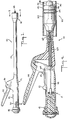
- FIG. 1 is a schematic representation of a surgical instrument used for establishing compression anastomosis, in accordance with the principles of the present invention, illustrating a general overall view of the device.
- FIG. 2 is an enlarged partial perspective view of the handle portion of the instrument depicted in FIG. 1 showing the aligning feature of the device locked in place rendering the driving feature operational.
- FIG. 3 is a partial schematic representation of a surgical instrument like that of FIG. 1 showing the head portion of the device and a modified intermediate portion.
- FIG. 3A is a view much like that depicted in FIG. 3 showing yet another modified intermediate portion.
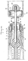
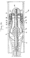
- FIG. 4 is an enlarged fragmented sectional view taken along the length of the instrument illustrated in FIG. 1, additionally including an uncoupled assembly, and showing the instrument and the assembly located in a colon but before assembly coupling and before the instrument is withdrawn from the patient leaving the assembly in place until the anastomosis has healed.
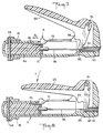
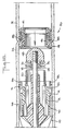
- FIG. 5 is an enlarged partially sectioned view of the handle portion of the instrument shown in FIG. 4 and depicting the coupling member aligning feature in an operative mode while the driving feature is locked against movement, positioning the coupling members in an orientation like that represented in FIG. 12.
- FIG. 6 is a view like that depicted in FIG. 5 but with the aligning feature in another position, the driving feature still being locked.
- FIG. 7 is a view somewhat like that illustrated in FIG. 6 but with the aligning feature being locked against movement and the driving feature in a operative mode prior to activation, the coupling members of the assembly being in a position like that shown in FIG. 13.
- FIG. 8 is a view substantially as shown in FIG. 7 but with the driving feature having been fully activated, the coupling members of the assembly being in a position like that shown in FIG. 15.
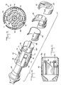
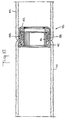
- FIG. 9 is an enlarged cross-sectional view taken along line 9-9 through the head portion of the instrument illustrated in FIG. 1.
- FIG. 10 is an exploded fragmentary perspective cutaway view of the head portion of the instrument, the outer housing having been removed, and including the coupling members of the assembly.
- FIG. 11 is an elongated cross-sectional view solely of the housing which forms a recess at the head portion location of the instrument.
- FIG. 12 is schematic sectional representation of the instrument, including members of the coupling assembly, being located in free ends of a sectioned colon but before the coupling members are moved into locking engagement.
- FIG. 13 is a schematic sectional representation similar to that illustrated in FIG. 12 showing members of the assembly approximated but before locking and before a cutting element advances to cut through captured colonic tissue and to cut through a coupling member of the assembly.
- FIG. 14 is similar to FIG. 13 but shows the coupling members fully locked and the initial rotational movement of the driver and the cutter as the cutter begins its passage through the tissue.
- FIG. 15 is similar to FIG. 14 and shows further rotational movement of the driver and particularly illustrates the rotational movement imparted to the cutter as the cutter passes through both the tissue and the coupling member.
- FIG. 16 is similar to FIG. 15 and shows the withdrawal of the instrument from the colon in the direction indicated.
- FIG. 17. is similar to FIG. 16 and illustrates that, after withdrawal of the instrument, the coupled assembly remains in the colon, which assembly will hold the captured colonic tissue in place until the anastomosis is healed and thereafter naturally be expelled intact by the patient.
- FIG. 1 there is illustrated a schematic representation of surgical instrument 10 of the present invention depicting a general overall view of the device.
- the instrument includes handle portion 12, intermediate portion 14 and head portion 16.
- knob 18, one of a pair of guide slots 20, safety locking element 22, lever 24, pivot pin 26 and core 28 are also shown on FIG. 1 and explained later in greater detail with respect to other drawing figures.
- FIGS. 2, 3 and 3A first there is illustrated in FIG. 2 an enlarged partial perspective view of handle portion 12 and in FIGS. 3 and 3A there is illustrated a partial schematic view showing head portion 16 and modified intermediate portions 14' and 14''.
- Portion 14' is curved at an angle with respect to the center line of the handle portion.
- Portion 14'' is a position retaining flexible member, like a gooseneck, which can assume a variety of orientations.
- Portion 14'' is capable of multiple planar orientation and may be manipulated to achieve 360° spherical rotation.
- the intermediate portion 14 of FIG. 1 is substantially straight and horizontal whereas in intermediate portion 14' of FIG. 3 the angle ⁇ might range from about 10° to about 25° with the preferred angle ⁇ being about 15°.
- FIG. 4 depicts a fragmented sectional view of instrument 10, taken along the length of the instrument with a segment of intermediate portion 14 removed, showing the instrument located in colon 30 having wall portions 32, 34, and being used in conjunction with coupled assembly 40 including coupling members 42, 44 and 46 (46 not being shown in this view).
- Coupling member 42 is carried by core 28 and held thereon by end knob 48 coupled to core 28.
- FIG. 5 depicts the aligning feature of instrument 10 in a first operative location positioning coupling member 42 of assembly 40 as shown in FIG. 12.
- the aligning feature comprises movable element 50 (located in handle portion 12) having recess 52 disposed therein and coupled at one end to core 28 and at the other end to knob 18 via pin 54.
- the movement of element 50 is guided within the handle by means of pin 54 traveling along slots 20 which have a curved portion 56 at one end of each slot.
- Each slot 20 might further include notches 21 for positioning element 50 at selected locations along the slot by locating pin 54 in the desired notch.
- FIG. 5 further depicts driving means 58 engaging end cap 60 of conduit 62.
- the end cap and conduit are slidably positioned in bore 63 running through intermediate portion 14 and intersecting a recess (FIG. 11) in head portion 16.
- Core 28 which might be either flexible or rigid, is slidably disposed in conduit 62, which also might be either flexible or rigid.
- a flexible conduit and a flexible core are preferred, particularly when intermediate portion 14 assumes a configuration other than straight. In an alternate construction, not shown, the conduit could be slidably disposed in the core.
- FIG. 6 is a view much like that of FIG. 5 but now shows the aligning feature in a second operative location.
- Knob 18, element 50 and core 28 have moved toward the left, advancing coupling member 42 into approximation with coupling member 44 much like that shown in FIG. 13.
- Lever 24 and driving means 58 remain locked against movement.
- the rotation of knob 18 and element 50 from the locked position (leftmost along handle 12) to any of a number of operating locations along slot 20, twists core 28 and sets up torsional forces in the core.
- the torsional or twisting forces set up in the core serve to urge pin 54 into a locked position when the pin is located within a slot 21.
- FIG. 7 is a view much like that of FIG. 6 but now shows the aligning feature in another location.
- Knob 18, element 50 and core 28 have been moved to their leftmost operating location wherein knob 18, pin 54 and element 50 have been rotated into the position shown.
- Pin 54 has traveled through curved portions 56 of slots 20 completing the approximation of coupling members 42, 44 establishing compression between members 42, 44 as is shown in FIG. 13.
- the arrows indicate the direction of movement of locking element 22 wherein downward force P1 and rearward force P2 are applied to 22 placing one end of 22 in recess 52 of element 50 thereby locking knob 18, element 50 and core 28 against movement.
- Element 50 is generally circular and fits snugly in circular handle portion 12 so that, with the introduction of an end of locking element 22 into recess 52, element 50 cannot be rotated thus locking knob 18, pin 54 and core 28 against movement.
- FIG. 8 like FIG. 7 depicts locking element 22 in its leftmost position completely securing knob 18, core 28, element 50 and pin 54 against movement. With element 22 in this position, there is left an unobstructed pathway for the rotation of lever 24 about pivot 26 and the downward movement of projection 23 such that upon application of force F to lever 24 the lever rotates about pivot 26 causing driving means 58 to move end cap 60 and conduit 62 to the right.
- FIG. 8 like FIG. 7 depicts locking element 22 in its leftmost position completely securing knob 18, core 28, element 50 and pin 54 against movement.
- driving means 8 depicts the driving means at rest after full activation. It should be understood that contemplated within the scope of the invention would be comparable driving means, namely, but not limited to, devices such as energy storing devices, threaded devices, slidable collars or rotating slidable collars.
- FIG. 9 is an enlarged cross-sectional view of head portion 16 including outer housing 66 having recess 68, with driver 70 and core 28 located in recess or cavity 68. Additionally shown in FIG. 9 is that driver 70 includes tab 72 with projecting rib 74 and that tab 72 is positioned in guide channel 76 disposed in recess 68.
- FIG. 10 there is shown an exploded fragmentary perspective cutaway view of head portion 10 with outer housing 66 removed.
- FIG. 10 specifically depicts driver support 69, driver 70 with tab 72, rib 74 and ledge 75 and further including angled projection 78 near the base of the driver.
- FIG. 11 depicts a cross-sectional view of housing 66 and includes channel 76 having a sloping end portion 82, ramp 84 and groove 86.
- coupling member 44 is carried by housing 66 as the end of member 44 snaps into the housing at location of annular groove 86; coupling member 46 rests on the end portion of tabs 72; and cutter 80 rests on driver ledge 75.
- Linear movement of driver 70 within recess 68 is guided by the location of tabs 72 in channels 76 and rotational movement of the driver and cutter 80 is caused by the gliding coaction of angled projection 78 as it rides along sloping ramp 84.
- FIG. 12 shows instrument 10 and coupling members 42, 44, 46 located in colon 30. While herein illustrated and described is the use of the instrument and coupling members in conjunction with colon repair, it should be understood that use thereof is equally applicable for the repair of other tubular organs such as the large and small bowel and the oesophagus to name but a few.
- colon 30 having wall portions 32, 34 and free ends 36, 38 is shown with the free ends being gathered against core 28.
- Coupling member 42 supported by core 28 and end knob 48 is located in one end of colon 30 while head portion 16 is located in the other end of the colon.
- Coupling member 42 is ready to be moved into approximation with member 44.
- FIG. 13 shows the coupling members approximated, core 28 having been moved to the left to bring ends 36, 38 into contact, but before locking of the members and before tissue and coupling member cutting. Compression of tissue between members 42, 44 is achieved by the movement of knob 18 and pin 54 through curved portion 56 at the handle end of the instrument and member 42 is secured against movement by locking the aligning means in a manner heretofore specified.
- the coupling members are now ready for locking and cutting by the operation of driving means 58 and driver 70 wherein the driving means will urge the driver forward.
- FIGS. 14 and 15 depict further operation of the instrument.
- Driver 70 rests in channels 76 of housing 66 and the coacting configuration of the inner housing and driver glides the movement of the driver when the driving means is activated.
- driver 70 has tabs 72 and angled projections 78 with the tabs 72 being positioned in channels 76 and angled projections 78 contacting sloping ramp surface 84.
- the driver is adapted to first move linearly forward as tabs 72 advance in channels 76 and then to rotate as angled projections 78 ride along ramp surface 84.
- Tabs 72 push coupling member 46 forward until it snaps into coupling member 44, thus locking together coupling members 42, 44 and 46.
- tabs 72 which are flexible, bend inwardly as rib 74 of each tab rides along sloping surface 82 at the end of channel 76, gradually decreasing the inner diameter of the channel that the tab rides in, and the tabs move inside coupling member 46.
- Attached to driver 70 is cutter 80 which cuts excess tissue, namely, free colon ends 36, 38, and through cut ring or recess 43 located in coupling member 42.
- driver 70 is free to move further forward without moving the coupled members of the assembly. The driver moves forward, rotating as it advances, and imparts a rotary motion to cutter 80 which cuts through the tissue and the coupling member.
- FIG. 16 shows the withdrawal of instrument 10 from the colon leaving the coupled assembly at the anastomosis site as shown in FIG. 17.
- the anastomosis will heal in and about the region designated 88 and thereafter the assembly will naturally be expelled intact by the patient leaving colon 30, at the anastomotic site, with an open, unobstructed passageway substantially like that which existed before resectioning.
Abstract
Description
- The present patent application is divided out of EP-A-0336596.
- The present invention generally relates to an anastomosis of living tissue and, more particularly, it relates to a surgical instrument particularly adapted for use in the installation of an assembly of interlocking coupling members to achieve compression anastomosis of tubular structures. The instrument, developed to facilitate placement of the coupling assembly in a patient and to enhance in the removal of the instrument after placement, includes a novel locking feature to improve operational safety. Additionally, the instrument might include a cutting element which incorporates a rotary motion as the cutter advances through tissue and the coupling assembly. A unique coupling member aligning feature may be provided, to enhance performance both in positioning of the coupling members and in applying compressive force to the members, and a unique flexible portion may be provided, to accommodate a variety of surgical conditions.
- A compression anastomosis coupling assembly is typically used when a segment of colon, or like tubular organ, is to be resected. After a section of the colon is removed, leaving opposed, proximal and distal, free ends, coaxially oriented coupling members are introduced, aligned and brought into locking engagement. The coupled members capture and compress the free ends of the colon together to effect an anastomosis by holding tissue in compression until healing occurs. Blood supply to the captured tissue is restricted. Necrosis takes place in the area of the colon captured within the assembly without causing excessive inflammation and trauma. Thereafter, the coupled assembly detaches from the anastomotic site and is expelled spontaneously through the rectum. After assembly expulsion, the colon provides an open passageway at the anastomotic site substantially as that which existed before resectioning.
- Disclosure of a known type of surgical instrument used to install an assembly for circular anastomosis of hollow organs can be found in U.S. Patent 4, 681,108. This device advanced the then known art field by introducing a circular mechanical anastomotic gun suitable for performing circular anastomosis in hollow organs using a compressive device. Previously, in the majority of cases, a mechanical gun had been used in systems incorporating a number of metallic staples which were driven into tissue edges to achieve the anastomosis. Specifically, the device disclosed in the aforementioned patent includes three coaxial tubular elements, means for carrying and means for positioning members of a coupling assembly, a circular cutting blade, and a driving means for first advancing the coupling members into engagement and then advancing the cicrular blade for cutting. The new surgical instrument herein disclosed further advances the art field by an improved safety locking system which provides for alternately locking the instrument aligning and driving features. Specifically, the locking feature allows for either aligning or driving at a given instant but not simultaneously, namely, when the aligning feature is operational the driving feature is inoperative and, conversely, when the driving feature is operational the aligning feature is inoperative.
- A cutter which rotates as it advances can be included. The rotational movement of the cutter has the advantages of reducing the cutting force necessary to cut through both captured excess organ tissue and coupling member of the assembly to provide an open passageway for material passage therethrough. The existing patented instrument includes a threaded knob which is rotated for positioning the outer coupling element and for exerting a compressive force between the outer and intermediate coupling elements prior to full locking assembly of the coupling elements The present device enhances coupling member positioning by providing a sliding approximation system for easier and quicker operation Also, the present device might feature an automatic locking system for securing one of the coupling members in a variety of positions relative to the other coupling members as a further refinement of the sliding approximation system. Furthermore, the sliding approximation system is designed and configured to provide an increased mechanical advantage thus reducing the necessary force applied by the user to achieve compression between assembly coupling members.
- Also, the new instrument might be either disposable or reusable. Furthermore, the instrument might include an anatomically curved segment for ease in introducing the device into a patient. Lastly, an improvement not known in the art is that the instrument might be sufficiently flexible to accommodate a variety of anatomical orientations and operating conditions.
- The primary objective of the present invention is to further advance the art field by providing a surgical instrument which is used to establish compression anastomosis in tubular organs and which is an improvement over existing devices. Accordingly, herein disclosed is a surgical instrument which is especially designed and configured for greater ease in installation of a compression anastomosis coupling assembly.
- The device of the present invention is a novel surgical instrument designed and configured for installing a coupling assembly, having a plurality of coupling members, to establish compression anastomosis in a tubular organ. The instrument comprises a body having a bore and includes a driver, a cutter, and means for supporting coupling members of the assembly.
- The surgical instrument includes one or more locking means for alternately locking the driving means and the aligning means against movement. A locking device is adapted for movement between two locking positions. In a first location, the driving means is locked and the aligning means is operational whereas, in a second location, the aligning means is locked and the driving means is operational. Both the driving means and the aligning means are not simultaneously operative.
- Means for aligning the coupling members and means for driving the driver to urge the coupling members into locking engagement and advancing the cutter are provided.
- The driving means might include a conduit slidably disposed in the bore with the first end of the conduit being adapted to engage a lever and a second end of theconduit being adapted to engage the driver means. Preferably the instrument comprises a handle portion, an intermediate portion and a head portion, an intermediate portion and a head portion, with the head portion having a recess intersecting the bore and the recess including therein the driver and the cutter. The recess is dimensioned and configured to provide means for guiding the movement of the driver and means for imparting rotational movement to the cutter. Rotary movement of the cutter can be achieved by providing a ramp engaging a complementary projection wherein the projection, provided either on the driver or in the recess, glides along a coacting ramp surface. The intermediate portion of the instrument can either be straight or curved, with a curvature ranging from about 10° to about 25° and a preferred curvature being about 15°.
- In another contemplated form of the invention, the surgical instrument includes an aligning means comprising a core having a first end coupled to one of the coupling members of the assembly and a second end coupled to a movable element, a knob coupled to the element, and means disposed in the handle portion for guiding the movement of the element and the knob. Furthermore, the guide means might include at least one elongated slot cooperating with one or more pins for coupling the element and the knob. The slot might further be configured to provide a means for applying a compressive force between at least two of the coupling members through the coaction of the pin and a curve disposed in one end of the slot. Additionally, the slot might further include one or more notches along the length of the slot for releasably locking one of the coupling members in a number of positions relative to the other coupling members. The core might be slidably disposed in a conduit located in the bore. Alternatively, the conduit might be slidably disposed in the core located in the bore.
in yet another contemplated form of the invention, the surgical instrument comprises an intermediate portion having a tubular member including a flexible conduit and a flexible core located within the tubular member. The tubular member might further be a position retaining flexible member capable of multiple planar orientation and further be capable of manipulation to achieve 360° spherical rotation. - For a better understanding of the invention, its operating advantages and specific results obtained by its use, reference should be made to the corresponding drawings and descriptive matter in which there is illustrated and described typical embodiments of the invention.
- FIG. 1 is a schematic representation of a surgical instrument used for establishing compression anastomosis, in accordance with the principles of the present invention, illustrating a general overall view of the device.
- FIG. 2 is an enlarged partial perspective view of the handle portion of the instrument depicted in FIG. 1 showing the aligning feature of the device locked in place rendering the driving feature operational.
- FIG. 3 is a partial schematic representation of a surgical instrument like that of FIG. 1 showing the head portion of the device and a modified intermediate portion.
- FIG. 3A is a view much like that depicted in FIG. 3 showing yet another modified intermediate portion.
- FIG. 4 is an enlarged fragmented sectional view taken along the length of the instrument illustrated in FIG. 1, additionally including an uncoupled assembly, and showing the instrument and the assembly located in a colon but before assembly coupling and before the instrument is withdrawn from the patient leaving the assembly in place until the anastomosis has healed.
- FIG. 5 is an enlarged partially sectioned view of the handle portion of the instrument shown in FIG. 4 and depicting the coupling member aligning feature in an operative mode while the driving feature is locked against movement, positioning the coupling members in an orientation like that represented in FIG. 12.
- FIG. 6 is a view like that depicted in FIG. 5 but with the aligning feature in another position, the driving feature still being locked.
- FIG. 7 is a view somewhat like that illustrated in FIG. 6 but with the aligning feature being locked against movement and the driving feature in a operative mode prior to activation, the coupling members of the assembly being in a position like that shown in FIG. 13.
- FIG. 8 is a view substantially as shown in FIG. 7 but with the driving feature having been fully activated, the coupling members of the assembly being in a position like that shown in FIG. 15.
- FIG. 9 is an enlarged cross-sectional view taken along line 9-9 through the head portion of the instrument illustrated in FIG. 1.
- FIG. 10 is an exploded fragmentary perspective cutaway view of the head portion of the instrument, the outer housing having been removed, and including the coupling members of the assembly.
- FIG. 11 is an elongated cross-sectional view solely of the housing which forms a recess at the head portion location of the instrument.
- FIG. 12 is schematic sectional representation of the instrument, including members of the coupling assembly, being located in free ends of a sectioned colon but before the coupling members are moved into locking engagement.
- FIG. 13 is a schematic sectional representation similar to that illustrated in FIG. 12 showing members of the assembly approximated but before locking and before a cutting element advances to cut through captured colonic tissue and to cut through a coupling member of the assembly.
- FIG. 14 is similar to FIG. 13 but shows the coupling members fully locked and the initial rotational movement of the driver and the cutter as the cutter begins its passage through the tissue.
- FIG. 15 is similar to FIG. 14 and shows further rotational movement of the driver and particularly illustrates the rotational movement imparted to the cutter as the cutter passes through both the tissue and the coupling member.
- FIG. 16 is similar to FIG. 15 and shows the withdrawal of the instrument from the colon in the direction indicated.
- FIG. 17. is similar to FIG. 16 and illustrates that, after withdrawal of the instrument, the coupled assembly remains in the colon, which assembly will hold the captured colonic tissue in place until the anastomosis is healed and thereafter naturally be expelled intact by the patient.
- The description herein presented refers to the accompanying drawings in which like reference numerals refer to like parts throughout the several views. First turning to FIG. 1 there is illustrated a schematic representation of
surgical instrument 10 of the present invention depicting a general overall view of the device. The instrument includeshandle portion 12,intermediate portion 14 andhead portion 16. Also shown on FIG. 1 and explained later in greater detail with respect to other drawing figures areknob 18, one of a pair ofguide slots 20,safety locking element 22,lever 24,pivot pin 26 andcore 28. Turning now to FIGS. 2, 3 and 3A, first there is illustrated in FIG. 2 an enlarged partial perspective view ofhandle portion 12 and in FIGS. 3 and 3A there is illustrated a partial schematic view showinghead portion 16 and modified intermediate portions 14' and 14''. Portion 14' is curved at an angle with respect to the center line of the handle portion. Portion 14'' is a position retaining flexible member, like a gooseneck, which can assume a variety of orientations. Portion 14'' is capable of multiple planar orientation and may be manipulated to achieve 360° spherical rotation. Theintermediate portion 14 of FIG. 1 is substantially straight and horizontal whereas in intermediate portion 14' of FIG. 3 the angle α might range from about 10° to about 25° with the preferred angle α being about 15°. FIG. 4 depicts a fragmented sectional view ofinstrument 10, taken along the length of the instrument with a segment ofintermediate portion 14 removed, showing the instrument located incolon 30 havingwall portions coupling members member 42 is carried bycore 28 and held thereon byend knob 48 coupled tocore 28. - Now turning to FIGS. 5 through 8, there is best seen the operation of aligning, locking and driving features associated with the operation of
instrument 10, which features are located inhandle portion 12. Specifically, FIG. 5 depicts the aligning feature ofinstrument 10 in a first operative location positioning couplingmember 42 of assembly 40 as shown in FIG. 12. The aligning feature comprises movable element 50 (located in handle portion 12) havingrecess 52 disposed therein and coupled at one end tocore 28 and at the other end toknob 18 viapin 54. The movement ofelement 50 is guided within the handle by means ofpin 54 traveling alongslots 20 which have acurved portion 56 at one end of each slot. Eachslot 20 might further includenotches 21 forpositioning element 50 at selected locations along the slot by locatingpin 54 in the desired notch. Full operation of the aligning feature will be discussed in respect to FIGS. 6 and 7. FIG. 5 further depicts driving means 58engaging end cap 60 ofconduit 62. The end cap and conduit are slidably positioned inbore 63 running throughintermediate portion 14 and intersecting a recess (FIG. 11) inhead portion 16.Core 28, which might be either flexible or rigid, is slidably disposed inconduit 62, which also might be either flexible or rigid. A flexible conduit and a flexible core are preferred, particularly whenintermediate portion 14 assumes a configuration other than straight. In an alternate construction, not shown, the conduit could be slidably disposed in the core. FIG. 5shows locking element 22, in one position, locking driving means 58 against movement wherein at location 64 a portion oflever 24 rests against the top surface of lockingelement 22 thereby precludinglever 24 from pivoting aboutpin 26 and drivingconduit 62 towardhead portion 16. As can be seen in the perspective representation of FIG. 2, ifelement 22 were advanced towardhead portion 16,downward projection 23 would abut the top surface ofelement 22 precluding downward movement oflever 24. - FIG. 6 is a view much like that of FIG. 5 but now shows the aligning feature in a second operative location.
Knob 18,element 50 andcore 28 have moved toward the left, advancingcoupling member 42 into approximation withcoupling member 44 much like that shown in FIG. 13.Lever 24 and driving means 58 remain locked against movement. The rotation ofknob 18 andelement 50, from the locked position (leftmost along handle 12) to any of a number of operating locations alongslot 20,twists core 28 and sets up torsional forces in the core. The torsional or twisting forces set up in the core serve to urgepin 54 into a locked position when the pin is located within aslot 21. FIG. 7 is a view much like that of FIG. 6 but now shows the aligning feature in another location.Knob 18,element 50 andcore 28 have been moved to their leftmost operating location whereinknob 18,pin 54 andelement 50 have been rotated into the position shown.Pin 54 has traveled throughcurved portions 56 ofslots 20 completing the approximation ofcoupling members members element 22 wherein downward force P₁ and rearward force P₂ are applied to 22 placing one end of 22 inrecess 52 ofelement 50 thereby lockingknob 18,element 50 andcore 28 against movement.Element 50 is generally circular and fits snugly incircular handle portion 12 so that, with the introduction of an end of lockingelement 22 intorecess 52,element 50 cannot be rotated thus lockingknob 18,pin 54 andcore 28 against movement. Although not shown, contemplated to be within the scope of the invention could be two locks that independently perform the dual locking functions of lockingelement 22. In the position shown, lockingelement 22 has been moved to allow for activation oflever 24 and driving means 58 sincelever 24 is now free for rotation aboutpivot pin 26. However, in this view the lever and driving means have not been activated. FIG. 8 like FIG. 7 depicts lockingelement 22 in its leftmost position completely securingknob 18,core 28,element 50 andpin 54 against movement. Withelement 22 in this position, there is left an unobstructed pathway for the rotation oflever 24 aboutpivot 26 and the downward movement ofprojection 23 such that upon application of force F to lever 24 the lever rotates aboutpivot 26 causing driving means 58 to moveend cap 60 andconduit 62 to the right. FIG. 8 depicts the driving means at rest after full activation. It should be understood that contemplated within the scope of the invention would be comparable driving means, namely, but not limited to, devices such as energy storing devices, threaded devices, slidable collars or rotating slidable collars. - Turning now to FIGS. 9 through 11, there are shown details of the head portion of the instrument. Specifically, FIG. 9 is an enlarged cross-sectional view of
head portion 16 includingouter housing 66 havingrecess 68, withdriver 70 andcore 28 located in recess orcavity 68. Additionally shown in FIG. 9 is thatdriver 70 includestab 72 with projectingrib 74 and thattab 72 is positioned inguide channel 76 disposed inrecess 68. In FIG. 10, there is shown an exploded fragmentary perspective cutaway view ofhead portion 10 withouter housing 66 removed. FIG. 10 specifically depictsdriver support 69,driver 70 withtab 72,rib 74 andledge 75 and further includingangled projection 78 near the base of the driver. Furthermore there are showncutter 80 andcoupling members member 42 further includingrecess 43. FIG. 11 depicts a cross-sectional view ofhousing 66 and includeschannel 76 having asloping end portion 82,ramp 84 andgroove 86. In assembly for operation,coupling member 44 is carried byhousing 66 as the end ofmember 44 snaps into the housing at location ofannular groove 86; couplingmember 46 rests on the end portion oftabs 72; andcutter 80 rests ondriver ledge 75. Linear movement ofdriver 70 withinrecess 68 is guided by the location oftabs 72 inchannels 76 and rotational movement of the driver andcutter 80 is caused by the gliding coaction ofangled projection 78 as it rides along slopingramp 84. - Let us now turn to FIGS. 12 through 17 where there are shown a series of schematic views depicting the operation of the surgical instrument. FIG. 12
shows instrument 10 andcoupling members colon 30. While herein illustrated and described is the use of the instrument and coupling members in conjunction with colon repair, it should be understood that use thereof is equally applicable for the repair of other tubular organs such as the large and small bowel and the oesophagus to name but a few. Here,colon 30 havingwall portions core 28. Couplingmember 42 supported bycore 28 andend knob 48 is located in one end ofcolon 30 whilehead portion 16 is located in the other end of the colon. Couplingmember 42 is ready to be moved into approximation withmember 44. FIG. 13 shows the coupling members approximated,core 28 having been moved to the left to bring ends 36, 38 into contact, but before locking of the members and before tissue and coupling member cutting. Compression of tissue betweenmembers knob 18 andpin 54 throughcurved portion 56 at the handle end of the instrument andmember 42 is secured against movement by locking the aligning means in a manner heretofore specified. The coupling members are now ready for locking and cutting by the operation of driving means 58 anddriver 70 wherein the driving means will urge the driver forward. FIGS. 14 and 15 depict further operation of the instrument.Driver 70 rests inchannels 76 ofhousing 66 and the coacting configuration of the inner housing and driver glides the movement of the driver when the driving means is activated. Specifically,driver 70 hastabs 72 andangled projections 78 with thetabs 72 being positioned inchannels 76 andangled projections 78 contacting slopingramp surface 84. The driver is adapted to first move linearly forward astabs 72 advance inchannels 76 and then to rotate asangled projections 78 ride alongramp surface 84.Tabs 72push coupling member 46 forward until it snaps intocoupling member 44, thus locking together couplingmembers tabs 72, which are flexible, bend inwardly asrib 74 of each tab rides along slopingsurface 82 at the end ofchannel 76, gradually decreasing the inner diameter of the channel that the tab rides in, and the tabs move insidecoupling member 46. Attached todriver 70 iscutter 80 which cuts excess tissue, namely, free colon ends 36, 38, and through cut ring orrecess 43 located in couplingmember 42. Whentabs 72 fold inwardly,driver 70 is free to move further forward without moving the coupled members of the assembly. The driver moves forward, rotating as it advances, and imparts a rotary motion tocutter 80 which cuts through the tissue and the coupling member. The rotation ofcutter 80 facilitates the smooth cutting action necessary to cut the tissue and the coupling member, clearing the lumen and allowing for the detachment of the instrument from the assembly.Rib 74 bumps an end ofmember 46 pushingmember 46 and coupledmember 44 dislodgingmember 44 from its attachment tohousing 66 atgroove 86 and freeing the coupled assembly frominstrument 10. FIG. 16 shows the withdrawal ofinstrument 10 from the colon leaving the coupled assembly at the anastomosis site as shown in FIG. 17. The anastomosis will heal in and about the region designated 88 and thereafter the assembly will naturally be expelled intact by thepatient leaving colon 30, at the anastomotic site, with an open, unobstructed passageway substantially like that which existed before resectioning.
Claims (9)
- A device (10) for introduction into a tubular bodily structure for installing an annular coupling assembly (40) having a plurality of coupling members (42, 44, 46) which can be urged into mutual locking engagement for compression anastomosis of the tubular structure followed by withdrawal of the device from the body, the device comprising:
a body having a bore (63) located therein and including a handle portion (12), an intermediate portion (14) and a head portion (16), with said head portion (16) having a recess (68) intersecting said bore (63);
said recess (68) containing driver means and cutter means for cutting the tubular structure on an annulus radially inwardly of the coupling assembly;
means for supporting the coupling members (42, 44, 46) of said assembly (40);
means for aligning said coupling members;
means actuated by the handle for driving said driver means for urging said coupling members into locking engagement and advancing said cutter means; and
one or more locking means for alternately locking said driving means and said aligning means against movement. - A device (10) according to claim 1 characterised in that said locking means is adapted for movement between first and second locking positions.
- A device (10) according to claim 1 characterized in that said locking means in a first position releasably locks said driving means against movement while simultaneously allowing operation of said aligning means, said driving means being inoperative while said aligning means is operational.
- A device (10) according to claim 2 or 3, characterized in that said locking means in a second position releasably locks said aligning means against movement while simultaneously allowing operation of said driving means, said aligning means being inoperative while said driving means is operational.
- A device (10) as claimed in any one of the preceding claims, said aligning means comprising a core (28) having a first end coupled to one of said coupling members and a second end coupled to a movable element (50), a knob (18) coupled to said element (50), and means disposed in said handle portion (12) for guiding the movement of said element (50) and said knob (18); and
means for driving said driver means for urging said coupling members into locking engagement and advancing said cutter means. - A device (10) according to claim 5 characterized in that said guide means includes at least one elongate slot (20) cooperating with at least one pin (54) coupling said element (50) and said knob (18) adapted for positioning said one coupling member relative to the other said coupling members.
- A device (10) according to claim 6 characterized in that said guide means further includes means for applying a compressive force between at least two of said coupling members.
- A device (10) according to claim 7 characterized in that said compressive force is achieved through a coaction of said pin (54) and a curve (56) disposed in one end of said slot (20).
- A device (10) according to claim 6, 7 or 8, characterized in that said slot (20) further includes one or more notches (21) disposed along said slot (20) for releasably locking said one coupling member in one or more positions relative to the other said coupling members.
Applications Claiming Priority (2)
| Application Number | Priority Date | Filing Date | Title |
|---|---|---|---|
| US174570 | 1988-03-29 | ||
| US07/174,570 US4907591A (en) | 1988-03-29 | 1988-03-29 | Surgical instrument for establishing compression anastomosis |
Related Parent Applications (1)
| Application Number | Title | Priority Date | Filing Date |
|---|---|---|---|
| EP89302744.1 Division | 1989-03-20 |
Publications (1)
| Publication Number | Publication Date |
|---|---|
| EP0509554A1 true EP0509554A1 (en) | 1992-10-21 |
Family
ID=22636647
Family Applications (3)
| Application Number | Title | Priority Date | Filing Date |
|---|---|---|---|
| EP19920110329 Withdrawn EP0503689A3 (en) | 1988-03-29 | 1989-03-20 | Surgical instrument for establishing compression anastomosis |
| EP92110328A Ceased EP0509554A1 (en) | 1988-03-29 | 1989-03-20 | Surgical instrument for establishing compression anastomosis |
| EP89302744A Expired - Lifetime EP0336596B1 (en) | 1988-03-29 | 1989-03-20 | Surgigal instrument for establishing compression anastomosis |
Family Applications Before (1)
| Application Number | Title | Priority Date | Filing Date |
|---|---|---|---|
| EP19920110329 Withdrawn EP0503689A3 (en) | 1988-03-29 | 1989-03-20 | Surgical instrument for establishing compression anastomosis |
Family Applications After (1)
| Application Number | Title | Priority Date | Filing Date |
|---|---|---|---|
| EP89302744A Expired - Lifetime EP0336596B1 (en) | 1988-03-29 | 1989-03-20 | Surgigal instrument for establishing compression anastomosis |
Country Status (15)
| Country | Link |
|---|---|
| US (1) | US4907591A (en) |
| EP (3) | EP0503689A3 (en) |
| JP (1) | JPH01310653A (en) |
| AT (1) | ATE91608T1 (en) |
| AU (3) | AU3176089A (en) |
| BR (1) | BR8901433A (en) |
| CA (1) | CA1315170C (en) |
| DE (2) | DE68907627T2 (en) |
| DK (1) | DK170036B1 (en) |
| ES (1) | ES2043002T3 (en) |
| FI (1) | FI891469A (en) |
| IL (1) | IL89710A0 (en) |
| NO (1) | NO175614C (en) |
| PT (1) | PT90136B (en) |
| ZA (1) | ZA892263B (en) |
Cited By (1)
| Publication number | Priority date | Publication date | Assignee | Title |
|---|---|---|---|---|
| US9707005B2 (en) | 2014-02-14 | 2017-07-18 | Ethicon Llc | Lockout mechanisms for surgical devices |
Families Citing this family (331)
| Publication number | Priority date | Publication date | Assignee | Title |
|---|---|---|---|---|
| GR880100632A (en) * | 1988-09-23 | 1990-10-31 | Guskov Igor A | Surgical suturing instrument |
| US5088979A (en) * | 1990-10-11 | 1992-02-18 | Wilson-Cook Medical Inc. | Method for esophageal invagination and devices useful therein |
| US5122156A (en) * | 1990-12-14 | 1992-06-16 | United States Surgical Corporation | Apparatus for securement and attachment of body organs |
| US5579978A (en) * | 1991-10-18 | 1996-12-03 | United States Surgical Corporation | Apparatus for applying surgical fasteners |
| US5443198A (en) * | 1991-10-18 | 1995-08-22 | United States Surgical Corporation | Surgical fastener applying apparatus |
| US5474223A (en) * | 1991-10-18 | 1995-12-12 | United States Surgical Corporation | Surgical fastener applying apparatus |
| US5197649A (en) * | 1991-10-29 | 1993-03-30 | The Trustees Of Columbia University In The City Of New York | Gastrointestinal endoscoptic stapler |
| US5271543A (en) * | 1992-02-07 | 1993-12-21 | Ethicon, Inc. | Surgical anastomosis stapling instrument with flexible support shaft and anvil adjusting mechanism |
| US5425738A (en) * | 1992-04-08 | 1995-06-20 | American Cyanamid Company | Endoscopic anastomosis ring insertion device and method of use thereof |
| US5282810A (en) * | 1992-04-08 | 1994-02-01 | American Cyanamid Company | Surgical anastomosis device |
| FR2691352A1 (en) * | 1992-05-19 | 1993-11-26 | Giraud Sheherazade | Circular stapler with variable diameter for surgical suturing of hollow organs using staples. |
| US5376098A (en) * | 1992-10-09 | 1994-12-27 | United States Surgical Corporation | Fragmentable anastomosis ring applier |
| US5454824A (en) * | 1992-10-09 | 1995-10-03 | United States Surgical Corporation | Fragmentable ring applier |
| CA2107848C (en) * | 1992-10-09 | 2005-04-12 | Frank J. Viola | Surgical fastener applying apparatus |
| US5364389A (en) * | 1992-11-25 | 1994-11-15 | Premier Laser Systems, Inc. | Method and apparatus for sealing and/or grasping luminal tissue |
| CA2132917C (en) * | 1993-10-07 | 2004-12-14 | John Charles Robertson | Circular anastomosis device |
| US5503635A (en) * | 1993-11-12 | 1996-04-02 | United States Surgical Corporation | Apparatus and method for performing compressional anastomoses |
| US5562690A (en) * | 1993-11-12 | 1996-10-08 | United States Surgical Corporation | Apparatus and method for performing compressional anastomoses |
| US5465894A (en) * | 1993-12-06 | 1995-11-14 | Ethicon, Inc. | Surgical stapling instrument with articulated stapling head assembly on rotatable and flexible support shaft |
| US5881943A (en) | 1994-06-17 | 1999-03-16 | Heartport, Inc. | Surgical anastomosis apparatus and method thereof |
| US5732872A (en) | 1994-06-17 | 1998-03-31 | Heartport, Inc. | Surgical stapling instrument |
| US7235089B1 (en) | 1994-12-07 | 2007-06-26 | Boston Scientific Corporation | Surgical apparatus and method |
| US5695504A (en) * | 1995-02-24 | 1997-12-09 | Heartport, Inc. | Devices and methods for performing a vascular anastomosis |
| US5976159A (en) | 1995-02-24 | 1999-11-02 | Heartport, Inc. | Surgical clips and methods for tissue approximation |
| US6110187A (en) * | 1995-02-24 | 2000-08-29 | Heartport, Inc. | Device and method for minimizing heart displacements during a beating heart surgical procedure |
| US5904697A (en) | 1995-02-24 | 1999-05-18 | Heartport, Inc. | Devices and methods for performing a vascular anastomosis |
| US20020019642A1 (en) * | 1996-07-23 | 2002-02-14 | Keith Milliman | Anastomosis instrument and method for performing same |
| US20050143769A1 (en) * | 2002-08-19 | 2005-06-30 | White Jeffrey S. | Ultrasonic dissector |
| CA2213948C (en) | 1996-09-19 | 2006-06-06 | United States Surgical Corporation | Ultrasonic dissector |
| US6109500A (en) | 1996-10-04 | 2000-08-29 | United States Surgical Corporation | Lockout mechanism for a surgical stapler |
| US5957879A (en) * | 1997-01-24 | 1999-09-28 | Heartport, Inc. | Methods and devices for maintaining cardiopulmonary bypass and arresting a patient's heart |
| US6035856A (en) * | 1997-03-06 | 2000-03-14 | Scimed Life Systems | Percutaneous bypass with branching vessel |
| US6026814A (en) * | 1997-03-06 | 2000-02-22 | Scimed Life Systems, Inc. | System and method for percutaneous coronary artery bypass |
| US6155264A (en) * | 1997-03-06 | 2000-12-05 | Scimed Life Systems, Inc. | Percutaneous bypass by tunneling through vessel wall |
| US6443158B1 (en) | 1997-06-19 | 2002-09-03 | Scimed Life Systems, Inc. | Percutaneous coronary artery bypass through a venous vessel |
| US6213126B1 (en) | 1997-06-19 | 2001-04-10 | Scimed Life Systems, Inc. | Percutaneous artery to artery bypass using heart tissue as a portion of a bypass conduit |
| US6092526A (en) * | 1997-06-19 | 2000-07-25 | Scimed Life Systems, Inc. | Percutaneous chamber-to-artery bypass |
| US6024750A (en) * | 1997-08-14 | 2000-02-15 | United States Surgical | Ultrasonic curved blade |
| US5954746A (en) * | 1997-10-09 | 1999-09-21 | Ethicon Endo-Surgery, Inc. | Dual cam trigger for a surgical instrument |
| NL1007349C2 (en) * | 1997-10-24 | 1999-04-27 | Suyker Wilhelmus Joseph Leonardus | System for the mechanical production of anastomoses between hollow structures; as well as device and applicator for use therewith. |
| US6086600A (en) | 1997-11-03 | 2000-07-11 | Symbiosis Corporation | Flexible endoscopic surgical instrument for invagination and fundoplication |
| US6551328B2 (en) | 1997-11-03 | 2003-04-22 | Symbiosis Corporation | Surgical instrument for invagination and fundoplication |
| US6193734B1 (en) | 1998-01-23 | 2001-02-27 | Heartport, Inc. | System for performing vascular anastomoses |
| US6352543B1 (en) * | 2000-04-29 | 2002-03-05 | Ventrica, Inc. | Methods for forming anastomoses using magnetic force |
| US6280460B1 (en) | 1998-02-13 | 2001-08-28 | Heartport, Inc. | Devices and methods for performing vascular anastomosis |
| US6176864B1 (en) * | 1998-03-09 | 2001-01-23 | Corvascular, Inc. | Anastomosis device and method |
| US6241741B1 (en) | 1998-03-09 | 2001-06-05 | Corvascular Surgical Systems, Inc. | Anastomosis device and method |
| US6110188A (en) * | 1998-03-09 | 2000-08-29 | Corvascular, Inc. | Anastomosis method |
| US6629630B2 (en) | 1998-06-19 | 2003-10-07 | Scimed Life Systems, Inc. | Non-circular resection device and endoscope |
| US6601749B2 (en) | 1998-06-19 | 2003-08-05 | Scimed Life Systems, Inc. | Multi fire full thickness resectioning device |
| US6461320B1 (en) | 1998-08-12 | 2002-10-08 | Cardica, Inc. | Method and system for attaching a graft to a blood vessel |
| US6206913B1 (en) | 1998-08-12 | 2001-03-27 | Vascular Innovations, Inc. | Method and system for attaching a graft to a blood vessel |
| DE19836950B4 (en) * | 1998-08-17 | 2004-09-02 | Deutsches Zentrum für Luft- und Raumfahrt e.V. | Surgical instrument in the form of a suturing device |
| US6325813B1 (en) | 1998-08-18 | 2001-12-04 | Scimed Life Systems, Inc. | Method and apparatus for stabilizing vascular wall |
| US6117147A (en) * | 1998-09-30 | 2000-09-12 | Sulzer Carbomedics Inc. | Device and method for reinforcing an anastomotic site |
| US7018387B2 (en) * | 1998-10-22 | 2006-03-28 | Innovative Interventional Technologies B.V. | Mechanical anastomosis system for hollow structures |
| US6743244B2 (en) | 1999-04-16 | 2004-06-01 | Integrated Vascular Interventional Technologies, L.C. | Soft anvil apparatus for cutting anastomosis fenestra |
| US6623494B1 (en) | 1999-04-16 | 2003-09-23 | Integrated Vascular Interventional Technologies, L.C. (Ivit, Lc) | Methods and systems for intraluminally directed vascular anastomosis |
| US6726694B2 (en) | 1999-04-16 | 2004-04-27 | Integrated Vascular Interventional Technologies, L.C. (Ivit, Lc) | Intraluminally directed anvil apparatus and related methods and systems |
| US6551334B2 (en) | 1999-04-16 | 2003-04-22 | Integrated Vascular Interventional Technologies, Lc | Externally directed anastomosis systems and externally positioned anastomosis fenestra cutting apparatus |
| US6569173B1 (en) | 1999-12-14 | 2003-05-27 | Integrated Vascular Interventional Technologies, L.C. | Compression plate anastomosis apparatus |
| US7981126B2 (en) * | 1999-04-16 | 2011-07-19 | Vital Access Corporation | Locking compression plate anastomosis apparatus |
| US7160311B2 (en) * | 1999-04-16 | 2007-01-09 | Integrated Vascular Interventional Technologies, L.C. (Ivit Lc) | Locking compression plate anastomosis apparatus |
| US6652542B2 (en) | 1999-04-16 | 2003-11-25 | Integrated Vascular Interventional Technologies, L.C. (Ivit, Lc) | External anastomosis operators and related systems for anastomosis |
| US6248117B1 (en) | 1999-04-16 | 2001-06-19 | Vital Access Corp | Anastomosis apparatus for use in intraluminally directed vascular anastomosis |
| AU5150600A (en) * | 1999-05-18 | 2000-12-05 | Vascular Innovations, Inc. | Tissue punch |
| US7048751B2 (en) * | 2001-12-06 | 2006-05-23 | Cardica, Inc. | Implantable medical device such as an anastomosis device |
| US6428550B1 (en) | 1999-05-18 | 2002-08-06 | Cardica, Inc. | Sutureless closure and deployment system for connecting blood vessels |
| AU5143000A (en) | 1999-05-18 | 2000-12-05 | Vascular Innovations, Inc. | Implantable medical device such as an anastomosis device |
| US6719769B2 (en) | 1999-11-15 | 2004-04-13 | Cardica, Inc. | Integrated anastomosis tool with graft vessel attachment device and cutting device |
| US6673088B1 (en) | 1999-05-18 | 2004-01-06 | Cardica, Inc. | Tissue punch |
| US6793652B1 (en) | 1999-06-02 | 2004-09-21 | Power Medical Interventions, Inc. | Electro-mechanical surgical device |
| US6491201B1 (en) | 2000-02-22 | 2002-12-10 | Power Medical Interventions, Inc. | Fluid delivery mechanism for use with anastomosing, stapling, and resecting instruments |
| US6315184B1 (en) * | 1999-06-02 | 2001-11-13 | Powermed, Inc. | Stapling device for use with an electromechanical driver device for use with anastomosing, stapling, and resecting instruments |
| US8025199B2 (en) | 2004-02-23 | 2011-09-27 | Tyco Healthcare Group Lp | Surgical cutting and stapling device |
| US6443973B1 (en) | 1999-06-02 | 2002-09-03 | Power Medical Interventions, Inc. | Electromechanical driver device for use with anastomosing, stapling, and resecting instruments |
| US7951071B2 (en) | 1999-06-02 | 2011-05-31 | Tyco Healthcare Group Lp | Moisture-detecting shaft for use with an electro-mechanical surgical device |
| US7695485B2 (en) * | 2001-11-30 | 2010-04-13 | Power Medical Interventions, Llc | Surgical device |
| US6517565B1 (en) | 1999-06-02 | 2003-02-11 | Power Medical Interventions, Inc. | Carriage assembly for controlling a steering wire steering mechanism within a flexible shaft |
| US6981941B2 (en) * | 1999-06-02 | 2006-01-03 | Power Medical Interventions | Electro-mechanical surgical device |
| US6716233B1 (en) | 1999-06-02 | 2004-04-06 | Power Medical Interventions, Inc. | Electromechanical driver and remote surgical instrument attachment having computer assisted control capabilities |
| US6264087B1 (en) * | 1999-07-12 | 2001-07-24 | Powermed, Inc. | Expanding parallel jaw device for use with an electromechanical driver device |
| US6179849B1 (en) | 1999-06-10 | 2001-01-30 | Vascular Innovations, Inc. | Sutureless closure for connecting a bypass graft to a target vessel |
| US7014644B1 (en) | 1999-07-28 | 2006-03-21 | Cardica, Inc. | Tissue bonding system and method for controlling a tissue site during anastomosis |
| US7682368B1 (en) * | 1999-07-28 | 2010-03-23 | Cardica, Inc. | Anastomosis tool actuated with stored energy |
| US7285131B1 (en) * | 1999-07-28 | 2007-10-23 | Cardica, Inc. | System for performing anastomosis |
| US7300444B1 (en) | 1999-07-28 | 2007-11-27 | Cardica, Inc. | Surgical system and method for connecting hollow tissue structures |
| US7766924B1 (en) | 1999-07-28 | 2010-08-03 | Cardica, Inc. | System for performing anastomosis |
| US7371243B1 (en) | 1999-07-28 | 2008-05-13 | Cardica, Inc. | Surgical apparatus and method for anastomosis |
| US20050154406A1 (en) * | 1999-07-28 | 2005-07-14 | Cardica, Inc. | Method for anastomosing vessels |
| US7850703B2 (en) * | 1999-07-28 | 2010-12-14 | Cardica, Inc. | System for performing anastomosis |
| US6391038B2 (en) | 1999-07-28 | 2002-05-21 | Cardica, Inc. | Anastomosis system and method for controlling a tissue site |
| WO2001015607A1 (en) * | 1999-09-01 | 2001-03-08 | Origin Medsystems, Inc. | Method and apparatus for performing anastomosis |
| US20030130671A1 (en) * | 1999-11-23 | 2003-07-10 | Duhaylongsod Francis G. | Anastomosis device and method |
| US6736825B2 (en) * | 1999-12-14 | 2004-05-18 | Integrated Vascular Interventional Technologies, L C (Ivit Lc) | Paired expandable anastomosis devices and related methods |
| DE60127236T2 (en) | 2000-01-18 | 2007-11-22 | Tyco Healthcare Group Lp, Norwalk | Instrument for anastomosis |
| US6488197B1 (en) | 2000-02-22 | 2002-12-03 | Power Medical Interventions, Inc. | Fluid delivery device for use with anastomosing resecting and stapling instruments |
| US6348061B1 (en) | 2000-02-22 | 2002-02-19 | Powermed, Inc. | Vessel and lumen expander attachment for use with an electromechanical driver device |
| US6533157B1 (en) | 2000-02-22 | 2003-03-18 | Power Medical Interventions, Inc. | Tissue stapling attachment for use with an electromechanical driver device |
| US8016855B2 (en) | 2002-01-08 | 2011-09-13 | Tyco Healthcare Group Lp | Surgical device |
| US20050080439A1 (en) * | 2000-04-29 | 2005-04-14 | Carson Dean F. | Devices and methods for forming magnetic anastomoses and ports in vessels |
| US7232449B2 (en) * | 2000-04-29 | 2007-06-19 | Medtronic, Inc. | Components, systems and methods for forming anastomoses using magnetism or other coupling means |
| US8518062B2 (en) | 2000-04-29 | 2013-08-27 | Medtronic, Inc. | Devices and methods for forming magnetic anastomoses between vessels |
| US6776785B1 (en) * | 2000-10-12 | 2004-08-17 | Cardica, Inc. | Implantable superelastic anastomosis device |
| US20050234483A1 (en) * | 2000-11-06 | 2005-10-20 | Cardica, Inc. | Unitary anastomosis device |
| US6966917B1 (en) * | 2000-11-09 | 2005-11-22 | Innovation Interventional Technologies B.V. | Deformable connector for mechanically connecting hollow structures |
| US6471713B1 (en) | 2000-11-13 | 2002-10-29 | Cardica, Inc. | System for deploying an anastomosis device and method of performing anastomosis |
| US6554764B1 (en) | 2000-11-13 | 2003-04-29 | Cardica, Inc. | Graft vessel preparation device and methods for using the same |
| US6520971B1 (en) | 2000-11-27 | 2003-02-18 | Scimed Life Systems, Inc. | Full thickness resection device control handle |
| US20020143347A1 (en) * | 2000-12-13 | 2002-10-03 | Ventrica, Inc. | Extravascular anastomotic components and methods for forming vascular anastomoses |
| US7909837B2 (en) | 2000-12-13 | 2011-03-22 | Medtronic, Inc. | Methods, devices and systems for forming magnetic anastomoses |
| US20020095166A1 (en) * | 2001-01-16 | 2002-07-18 | Jaime Vargas | Incision tensioning system and method for using the same |
| US6890338B1 (en) * | 2001-02-27 | 2005-05-10 | Origin Medsystems, Inc. | Method and apparatus for performing anastomosis using ring having tines with weak sections |
| HUP0101033A2 (en) | 2001-03-10 | 2002-12-28 | László Csiky | Surgical stapling instrument with modified circular tool |
| JP4388745B2 (en) | 2001-04-03 | 2009-12-24 | タイコ ヘルスケア グループ リミテッド パートナーシップ | Surgical stapling device for performing annular anastomosis |
| US6994714B2 (en) * | 2001-04-27 | 2006-02-07 | Cardica, Inc. | Anastomosis system |
| ATE443476T1 (en) * | 2001-05-18 | 2009-10-15 | Ucl Business Plc | FLEXIBLE DEVICE FOR PIERCING AND JOINING TISSUE |
| US20070060952A1 (en) * | 2005-09-02 | 2007-03-15 | Roby Mark S | Surgical stapling device with coated knife blade |
| JP4346439B2 (en) | 2001-10-05 | 2009-10-21 | タイコ ヘルスケア グループ エルピー | Inclined top anvil for surgical fastener devices |
| US9113878B2 (en) | 2002-01-08 | 2015-08-25 | Covidien Lp | Pinion clip for right angle linear cutter |
| US7335216B2 (en) * | 2002-01-22 | 2008-02-26 | Cardica, Inc. | Tool for creating an opening in tissue |
| US7029482B1 (en) * | 2002-01-22 | 2006-04-18 | Cardica, Inc. | Integrated anastomosis system |
| US8012164B1 (en) | 2002-01-22 | 2011-09-06 | Cardica, Inc. | Method and apparatus for creating an opening in the wall of a tubular vessel |
| US7223274B2 (en) * | 2002-01-23 | 2007-05-29 | Cardica, Inc. | Method of performing anastomosis |
| US6905504B1 (en) * | 2002-02-26 | 2005-06-14 | Cardica, Inc. | Tool for performing end-to-end anastomosis |
| US6769594B2 (en) * | 2002-05-31 | 2004-08-03 | Tyco Healthcare Group, Lp | End-to-end anastomosis instrument and method for performing same |
| US7195142B2 (en) * | 2003-05-30 | 2007-03-27 | Tyco Healthcare Group Lp | End-to-end anastomosis instrument and method for performing same |
| JP4464816B2 (en) | 2002-06-14 | 2010-05-19 | パワー メディカル インターベンションズ, エルエルシー | Surgical device |
| ES2364043T3 (en) | 2002-07-31 | 2011-08-23 | Tyco Healthcare Group Lp | TOOL COATING ELEMENT AND COATING DEPLOYMENT DEVICE. |
| EP2055246B1 (en) * | 2002-10-04 | 2012-04-18 | Tyco Healthcare Group LP | Surgical stapling device |
| US20040217146A1 (en) * | 2002-12-20 | 2004-11-04 | Joachim Beck | Surgical stapler apparatus and method |
| US20040236178A1 (en) * | 2003-02-14 | 2004-11-25 | Cardica, Inc. | Method for preparing a graft vessel for anastomosis |
| ES2551683T3 (en) | 2003-06-20 | 2015-11-23 | Covidien Lp | Surgical stapling instrument |
| US7794471B1 (en) | 2003-06-26 | 2010-09-14 | Cardica, Inc. | Compliant anastomosis system |
| US8574246B1 (en) | 2004-06-25 | 2013-11-05 | Cardica, Inc. | Compliant anastomosis system utilizing suture |
| US6959851B2 (en) * | 2003-07-16 | 2005-11-01 | Tyco Healthcare Group Lp | Surgical stapling device with tissue tensioner |
| US6965203B2 (en) * | 2003-09-17 | 2005-11-15 | Synaptic Tan, Inc. | Method and circuit for repetitively firing a flash lamp or the like |
| US7364060B2 (en) | 2003-10-17 | 2008-04-29 | Tyco Healthcare Group Lp | Surgical stapling device with tiltable anvil head |
| US20050149073A1 (en) * | 2003-12-17 | 2005-07-07 | Arani Djavad T. | Mechanisms and methods used in the anastomosis of biological conduits |
| US7585306B2 (en) * | 2003-12-24 | 2009-09-08 | Maquet Cardiovascular Llc | Anastomosis device, tools and methods of using |
| US20080269784A1 (en) * | 2003-12-24 | 2008-10-30 | Ryan Abbott | Anastomosis device, tools and methods of using |
| US20050149071A1 (en) * | 2003-12-24 | 2005-07-07 | Ryan Abbott | Anastomosis device, tools and method of using |
| US20050203551A1 (en) * | 2004-03-09 | 2005-09-15 | Kevin Weadock | Method for performing a coronary artery bypass graft procedure |
| US7494038B2 (en) * | 2004-03-19 | 2009-02-24 | Tyco Healthcare Group Lp | Anvil assembly with improved cut ring |
| US8181840B2 (en) | 2004-03-19 | 2012-05-22 | Tyco Healthcare Group Lp | Tissue tensioner assembly and approximation mechanism for surgical stapling device |
| US8162963B2 (en) * | 2004-06-17 | 2012-04-24 | Maquet Cardiovascular Llc | Angled anastomosis device, tools and method of using |
| US7515970B2 (en) * | 2004-08-18 | 2009-04-07 | Cardiac Pacemakers, Inc. | Transeptal lead |
| EP1847225B1 (en) * | 2005-01-26 | 2011-12-21 | Suzhou Touchstone International Medical Science Co., Ltd. | Surgical stapler having a stapling head with a rotatable cutter |
| US20070142850A1 (en) * | 2005-12-15 | 2007-06-21 | David Fowler | Compression anastomosis device |
| US8540132B2 (en) | 2006-05-16 | 2013-09-24 | Covidien Lp | Tilt anvil assembly |
| US20080097501A1 (en) * | 2006-06-22 | 2008-04-24 | Tyco Healthcare Group Lp | Ultrasonic probe deflection sensor |
| ATE499048T1 (en) * | 2007-03-07 | 2011-03-15 | Covidien Ag | CLAPPER FOR MUCOSECTOMY |
| US8221326B2 (en) * | 2007-03-09 | 2012-07-17 | Nellcor Puritan Bennett Llc | Detection of oximetry sensor sites based on waveform characteristics |
| US8623035B1 (en) * | 2007-05-09 | 2014-01-07 | University Of South Florida | Methods for resection of a luminal structure |
| EP2168504B1 (en) * | 2007-06-28 | 2016-06-15 | Suzhou Touchstone International Medical Science Co., Ltd. | Rotary cutter head for surgical stapling instrument |
| US8929988B2 (en) | 2007-07-11 | 2015-01-06 | Apollo Endosurgery, Inc. | Methods and systems for submucosal implantation of a device for diagnosis and treatment of a body |
| US8128592B2 (en) | 2007-07-11 | 2012-03-06 | Apollo Endosurgery, Inc. | Methods and systems for performing submucosal medical procedures |
| US20100217151A1 (en) * | 2007-07-11 | 2010-08-26 | Zach Gostout | Methods and Systems for Performing Submucosal Medical Procedures |
| US8066689B2 (en) | 2007-07-11 | 2011-11-29 | Apollo Endosurgery, Inc. | Methods and systems for submucosal implantation of a device for diagnosis and treatment with a therapeutic agent |
| US8317771B2 (en) * | 2007-07-11 | 2012-11-27 | Apollo Endosurgery, Inc. | Methods and systems for performing submucosal medical procedures |
| US7967181B2 (en) | 2007-08-29 | 2011-06-28 | Tyco Healthcare Group Lp | Rotary knife cutting systems |
| US8070036B1 (en) | 2007-09-06 | 2011-12-06 | Cardica, Inc | True multi-fire surgical stapler configured to fire staples of different sizes |
| US9168039B1 (en) | 2007-09-06 | 2015-10-27 | Cardica, Inc. | Surgical stapler with staples of different sizes |
| US7988026B2 (en) * | 2007-09-06 | 2011-08-02 | Cardica, Inc. | Endocutter with staple feed |
| JP5425786B2 (en) | 2007-09-21 | 2014-02-26 | コヴィディエン リミテッド パートナーシップ | Surgical equipment |
| CA2698329C (en) | 2007-09-21 | 2016-04-26 | Power Medical Interventions, Llc | Surgical device |
| US8011554B2 (en) | 2008-01-09 | 2011-09-06 | Tyco Healthcare Group, Lp | Raised boss for staple guide |
| US20090287045A1 (en) | 2008-05-15 | 2009-11-19 | Vladimir Mitelberg | Access Systems and Methods of Intra-Abdominal Surgery |
| US8181838B2 (en) | 2008-09-10 | 2012-05-22 | Tyco Healthcare Group Lp | Surgical stapling device |
| US8231042B2 (en) | 2008-11-06 | 2012-07-31 | Tyco Healthcare Group Lp | Surgical stapler |
| US8281974B2 (en) | 2009-01-14 | 2012-10-09 | Tyco Healthcare, Group LP | Surgical stapler with suture locator |
| US8453913B2 (en) | 2009-02-06 | 2013-06-04 | Covidien Lp | Anvil for surgical stapler |
| US8167898B1 (en) | 2009-05-05 | 2012-05-01 | Cardica, Inc. | Flexible cutter for surgical stapler |
| US8146790B2 (en) | 2009-07-11 | 2012-04-03 | Tyco Healthcare Group Lp | Surgical instrument with safety mechanism |
| US8267301B2 (en) | 2009-08-19 | 2012-09-18 | Tyco Healthcare Group Lp | Surgical stapler |
| US8430292B2 (en) | 2009-10-28 | 2013-04-30 | Covidien Lp | Surgical fastening apparatus |
| US8413872B2 (en) | 2009-10-28 | 2013-04-09 | Covidien Lp | Surgical fastening apparatus |
| US8322590B2 (en) | 2009-10-28 | 2012-12-04 | Covidien Lp | Surgical stapling instrument |
| US8708212B2 (en) | 2011-10-18 | 2014-04-29 | Covidien Lp | Tilt top anvil with torsion spring |
| US9016547B2 (en) | 2011-10-26 | 2015-04-28 | Covidien Lp | EEA tilt top anvil with ratchet/locking mechanism |
| US9220505B2 (en) * | 2011-12-16 | 2015-12-29 | Ethicon Endo-Surgery, Inc. | Surgical stapling instrument with locking feature to lock anvil actuator |
| US9010605B2 (en) | 2012-01-12 | 2015-04-21 | Covidien Lp | Sliding sleeve for circular stapling instrument reloads |
| US9022274B2 (en) | 2012-02-15 | 2015-05-05 | Covidien Lp | Circular stapler with increased lumen diameter |
| US9351734B2 (en) | 2012-06-19 | 2016-05-31 | Covidien Lp | Spring loaded anvil retainer |
| US10213205B2 (en) | 2012-07-06 | 2019-02-26 | Covidien Lp | T-slot tilt anvil for circular stapling instrument |
| TWI626922B (en) * | 2012-09-20 | 2018-06-21 | 卡波諾凡股份有限公司 | A mounting tool for an anastomotic device |
| US9675359B2 (en) | 2012-10-10 | 2017-06-13 | Covidien Lp | Surgical instrument with preload assembly |
| US9572572B2 (en) | 2012-11-09 | 2017-02-21 | Covidien Lp | Circular stapler mechanical lockout |
| US9351724B2 (en) | 2013-01-11 | 2016-05-31 | Covidien Lp | Circular stapling instrument |
| US9592056B2 (en) | 2013-03-14 | 2017-03-14 | Covidien Lp | Powered stapling apparatus |
| CN104042292A (en) | 2013-03-15 | 2014-09-17 | 柯惠Lp公司 | Surgical anastomosis device comprising assemblies capable of being repeatedly utilized |
| US9532780B2 (en) | 2013-06-12 | 2017-01-03 | Covidien Lp | EEA anvil snap ring activator |
| US9668740B2 (en) | 2013-06-14 | 2017-06-06 | Covidien Lp | Anvil assembly with sliding sleeve |
| EP3010424A4 (en) | 2013-06-17 | 2017-06-07 | Covidien LP | Surgical instrument with lockout mechanism |
| US9750503B2 (en) | 2013-07-11 | 2017-09-05 | Covidien Lp | Methods and devices for performing a surgical anastomosis |
| US9693773B2 (en) | 2013-09-11 | 2017-07-04 | Covidien Lp | Anvil assembly with sliding sleeve |
| US9517070B2 (en) | 2013-11-13 | 2016-12-13 | Covidien Lp | Anvil assembly and delivery system |
| US9554802B2 (en) | 2013-11-13 | 2017-01-31 | Covidien Lp | Anvil assembly with frangible retaining member |
| US9913643B2 (en) | 2014-05-09 | 2018-03-13 | Covidien Lp | Interlock assemblies for replaceable loading unit |
| CN106456166B (en) | 2014-06-12 | 2019-11-01 | 柯惠有限合伙公司 | Surgical stapling device |
| US9861367B2 (en) | 2014-06-24 | 2018-01-09 | Covidien Lp | Anvil assembly delivery systems |
| US9867619B2 (en) | 2014-06-24 | 2018-01-16 | Covidien Lp | System for delivering an anvil assembly to a surgical site |
| US10405864B2 (en) | 2014-07-04 | 2019-09-10 | Covidien Lp | Loading unit with shipping member for surgical stapling device |
| US9757133B2 (en) | 2014-07-09 | 2017-09-12 | Covidien Lp | Methods and devices for performing a surgical anastomosis |
| US10898196B2 (en) | 2014-11-21 | 2021-01-26 | Covidien Lp | Cleaning apparatus for surgical instruments |
| US10085744B2 (en) | 2014-12-08 | 2018-10-02 | Covidien Lp | Loading unit attachment band for surgical stapling instrument |
| US9855045B2 (en) | 2014-12-09 | 2018-01-02 | Covidien Lp | Anvil assembly delivery system |
| JP6480585B2 (en) | 2014-12-11 | 2019-03-13 | コヴィディエン リミテッド パートナーシップ | Stapler with automatic detention mechanism |
| WO2016090594A1 (en) | 2014-12-11 | 2016-06-16 | Covidien Lp | Surgical stapling loading unit |
| US10542985B2 (en) | 2014-12-17 | 2020-01-28 | Covidien Lp | Surgical stapling device with firing indicator |
| US10039549B2 (en) | 2015-01-07 | 2018-08-07 | Covidien Lp | Loading unit retention clip for surgical stapling instrument |
| US10117656B2 (en) | 2015-01-07 | 2018-11-06 | Covidien Lp | Loading unit locking collar |
| US10022126B2 (en) | 2015-01-07 | 2018-07-17 | Covidien Lp | Loading unit locking collar |
| JP2018504987A (en) | 2015-02-15 | 2018-02-22 | コヴィディエン リミテッド パートナーシップ | Surgical stapling device having a monolithic firing indicator |
| US10881408B2 (en) | 2015-04-22 | 2021-01-05 | Covidien Lp | Interlock assembly for replaceable loading units |
| US10426480B2 (en) | 2015-04-29 | 2019-10-01 | Covidien Lp | Cutting ring assembly with rigid cutting member |
| US9987001B2 (en) | 2015-06-12 | 2018-06-05 | Covidien Lp | Surgical anastomosis apparatus |
| US9974536B2 (en) | 2015-07-02 | 2018-05-22 | Covidien Lp | Anvil assemblies and delivery systems |
| US10111668B2 (en) | 2015-07-02 | 2018-10-30 | Covidien Lp | Anvil assembly with snap backup ring |
| US10117655B2 (en) | 2015-07-22 | 2018-11-06 | Covidien Lp | Loading unit locking band for surgical stapling instrument |
| US10085756B2 (en) | 2015-07-24 | 2018-10-02 | Covidien Lp | Anvil assembly and anvil assembly delivery system |
| US10117675B2 (en) | 2015-07-28 | 2018-11-06 | Covidien Lp | Trocar tip protector |
| US9980730B2 (en) | 2015-09-21 | 2018-05-29 | Covidien Lp | Loading unit locking collar with rotational actuated release |
| US10111684B2 (en) | 2015-09-25 | 2018-10-30 | Covidien Lp | Adapter assembly including a removable trocar assembly |
| US10542992B2 (en) | 2015-10-19 | 2020-01-28 | Covidien Lp | Loading unit with stretchable bushing |
| US10973522B2 (en) | 2015-10-20 | 2021-04-13 | Covidien Lp | Circular stapler with tissue gap indicator assembly |
| US10842495B2 (en) | 2015-10-21 | 2020-11-24 | Covidien Lp | Annular knife for a surgical stapler |
| US10512466B2 (en) | 2015-11-05 | 2019-12-24 | Covidien Lp | Adapter assembly for surgical device |
| CN108289683B (en) | 2015-11-13 | 2021-06-25 | 柯惠有限合伙公司 | Circular stapler with audible indicator mechanism |
| CN108289684B (en) | 2015-12-07 | 2021-08-31 | 柯惠有限合伙公司 | Anvil assembly and delivery system |
| US10390835B2 (en) | 2015-12-10 | 2019-08-27 | Covidien Lp | Surgical fastener apparatus with linear position sensor |
| US10524797B2 (en) | 2016-01-13 | 2020-01-07 | Covidien Lp | Adapter assembly including a removable trocar assembly |
| JP6619103B2 (en) | 2016-02-04 | 2019-12-11 | コヴィディエン リミテッド パートナーシップ | Circular stapler with visual indicator mechanism |
| US10603042B2 (en) | 2016-02-10 | 2020-03-31 | Covidien Lp | Flexible circular stapler |
| US10398439B2 (en) | 2016-02-10 | 2019-09-03 | Covidien Lp | Adapter, extension, and connector assemblies for surgical devices |
| US10869729B2 (en) | 2016-03-04 | 2020-12-22 | Covidien Lp | Robotic surgical assemblies |
| US10595871B2 (en) | 2016-05-10 | 2020-03-24 | Covidien Lp | Insertion instrument, adapter assemblies and protector assemblies for a flexible circular stapler |
| US11141162B2 (en) | 2016-07-08 | 2021-10-12 | Covidien Lp | Loading unit locking collar with linearly actuated release |
| US11452522B2 (en) | 2016-08-15 | 2022-09-27 | Covidien Lp | Circular stapling device with articulating anvil retainer assembly |
| WO2018078589A1 (en) * | 2016-10-31 | 2018-05-03 | Abello Munarriz Cristobal Adolfo | Compression anastomosis device and mechanism for positioning and connecting same |
| US10426470B2 (en) | 2016-11-04 | 2019-10-01 | Covidien Lp | Stapling device with releasable knife carrier |
| US10499922B2 (en) | 2016-11-04 | 2019-12-10 | Covidien Lp | Stapling device with self-releasing knife carrier pusher |
| US11241232B2 (en) | 2017-01-24 | 2022-02-08 | Covidien Lp | Surgical stapling device with resettable anvil assembly |
| EP3639755B1 (en) | 2017-01-25 | 2021-06-23 | Covidien LP | Circular stapling device |
| US10307215B2 (en) * | 2017-02-02 | 2019-06-04 | Ethicon Llc | Locking articulating robotic surgical tools |
| US10542993B2 (en) | 2017-02-24 | 2020-01-28 | Covidien Lp | Anvil assembly of circular stapling device including alignment splines |
| EP3592251A4 (en) | 2017-03-09 | 2020-11-25 | Covidien LP | Surgical stapling device with audible indicator mechanism |
| CN110381852B (en) | 2017-03-09 | 2022-12-27 | 柯惠有限合伙公司 | End effector assembly for circular stapler apparatus |
| WO2018170831A1 (en) | 2017-03-23 | 2018-09-27 | Covidien Lp | Circular stapling device with alignment splines |
| US10342534B2 (en) | 2017-03-23 | 2019-07-09 | Covidien Lp | Surgical stapling device with releasable knife carrier |
| US10881409B2 (en) | 2017-05-02 | 2021-01-05 | Covidien Lp | Rotation assembly for a surgical device |
| US10932784B2 (en) | 2017-06-09 | 2021-03-02 | Covidien Lp | Handheld electromechanical surgical system |
| US11596400B2 (en) | 2017-06-09 | 2023-03-07 | Covidien Lp | Handheld electromechanical surgical system |
| US11045199B2 (en) | 2017-06-09 | 2021-06-29 | Covidien Lp | Handheld electromechanical surgical system |
| US10987107B2 (en) | 2017-07-05 | 2021-04-27 | Covidien Lp | Surgical stapling device |
| US11090054B2 (en) | 2017-08-07 | 2021-08-17 | Covidien Lp | Stapling device with resettable tilt anvil assembly |
| US10828026B2 (en) | 2017-08-08 | 2020-11-10 | Covidien Lp | Tiltable anvil assembly |
| US10695069B2 (en) | 2017-08-23 | 2020-06-30 | Covidien Lp | Circular stapling device with offset spline tip |
| CN111107796B (en) | 2017-09-01 | 2023-06-30 | 柯惠有限合伙公司 | Circular suturing device with positioning ribs |
| US11324507B2 (en) | 2017-11-03 | 2022-05-10 | Covidien Lp | Device and method for attachment of a stomal sleeve |
| US11497501B2 (en) | 2018-03-26 | 2022-11-15 | Covidien Lp | Circular stapling device with A-frame splines |
| US11033273B2 (en) | 2018-03-28 | 2021-06-15 | Covidien Lp | Surgical anvil assemblies for surgical stapling instruments |
| US10952734B2 (en) | 2018-04-23 | 2021-03-23 | Covidien Lp | Stapling device with cut ring biasing member |
| US11197676B2 (en) | 2018-06-28 | 2021-12-14 | Covidien Lp | Tie-down method for anvil assembly delivery system |
| US11241234B2 (en) | 2018-08-14 | 2022-02-08 | Covidien Lp | Anvil assembly with self-retaining backup member |
| US11564691B2 (en) | 2018-08-24 | 2023-01-31 | Covidien Lp | Powered circular stapling device |
| US10973544B2 (en) | 2018-10-02 | 2021-04-13 | Covidien Lp | Retaining mechanism for trocar assembly |
| US11141163B2 (en) | 2018-10-04 | 2021-10-12 | Covidien Lp | Circular stapling device with anvil rotation locking structure |
| US11207071B2 (en) * | 2018-10-15 | 2021-12-28 | Cilag Gmbh International | Dual stage closure system for circular surgical stapler |
| US11065005B2 (en) | 2018-11-07 | 2021-07-20 | Covidien Lp | Reload assembly for a circular stapling device |
| US11147561B2 (en) | 2018-11-28 | 2021-10-19 | Covidien Lp | Reload assembly for a circular stapling device |
| US11389263B2 (en) | 2018-12-13 | 2022-07-19 | Covidien Lp | Lockout mechanisms for surgical instruments |
| US11166728B2 (en) | 2019-02-08 | 2021-11-09 | Covidien Lp | Reload assembly for a circular stapling device |
| US11547411B2 (en) | 2019-02-22 | 2023-01-10 | Covidien Lp | Anastomosis wound protector |
| US11529144B2 (en) | 2019-02-22 | 2022-12-20 | Covidien Lp | Encapsulated plug assembly for electromechanical surgical devices |
| US11337701B2 (en) | 2019-03-01 | 2022-05-24 | Covidien Lp | Devices and methods for assembling adapter assemblies |
| US11331782B2 (en) | 2019-03-01 | 2022-05-17 | Covidien Lp | Reload assembly for a circular stapling device |
| US11457921B2 (en) | 2019-03-26 | 2022-10-04 | Covidien Lp | Anvil assembly for surgical stapling instrument |
| US11534164B2 (en) | 2019-04-05 | 2022-12-27 | Covidien Lp | Strain gauge stabilization in a surgical device |
| US11596410B2 (en) | 2019-04-05 | 2023-03-07 | Covidien Lp | Surgical stapling device |
| US11317945B2 (en) | 2019-04-16 | 2022-05-03 | Covidien Lp | Trocar assemblies for adapter assemblies for surgical stapling instruments |
| US11419631B2 (en) | 2019-04-16 | 2022-08-23 | Covidien Lp | Trocar assemblies for adapter assemblies for surgical stapling instruments |
| US11660116B2 (en) | 2019-04-16 | 2023-05-30 | Covidien Lp | Trocar assemblies for adapter assemblies for surgical stapling instruments |
| US11344330B2 (en) | 2019-04-16 | 2022-05-31 | Covidien Lp | Trocar assemblies for adapter assemblies for surgical stapling instruments |
| US11839378B2 (en) | 2019-04-19 | 2023-12-12 | Covidien Lp | Circular stapling instruments |
| US11399838B2 (en) | 2019-04-22 | 2022-08-02 | Covidien Lp | Reload assembly for circular stapling devices |
| US11246599B2 (en) * | 2019-04-25 | 2022-02-15 | Covidien Lp | End effector for circular stapling instrument |
| JP2022543958A (en) | 2019-05-31 | 2022-10-17 | コヴィディエン リミテッド パートナーシップ | circular stapling device |
| US11690624B2 (en) | 2019-06-21 | 2023-07-04 | Covidien Lp | Reload assembly injection molded strain gauge |
| US11123101B2 (en) | 2019-07-05 | 2021-09-21 | Covidien Lp | Retaining mechanisms for trocar assemblies |
| US11446035B2 (en) | 2019-06-24 | 2022-09-20 | Covidien Lp | Retaining mechanisms for trocar assemblies |
| US11344309B2 (en) | 2019-07-05 | 2022-05-31 | Covidien Lp | Circular stapling instruments |
| US11357509B2 (en) | 2019-07-11 | 2022-06-14 | Covidien Lp | Reload assembly for a circular stapling device |
| US11192227B2 (en) | 2019-07-16 | 2021-12-07 | Covidien Lp | Reload assembly for circular stapling devices |
| US11253255B2 (en) | 2019-07-26 | 2022-02-22 | Covidien Lp | Knife lockout wedge |
| US11464510B2 (en) | 2019-07-26 | 2022-10-11 | Covidien Lp | Reload assembly with knife carrier lockout |
| US11399825B2 (en) | 2019-10-28 | 2022-08-02 | Covidien Lp | Reload assembly with knife carrier lockout |
| US11553918B2 (en) | 2019-12-16 | 2023-01-17 | Covidien Lp | Reload assembly with knife carrier lockout |
| US11730481B2 (en) | 2020-01-06 | 2023-08-22 | Covidien Lp | Assemblies for retaining a trocar assembly |
| US11517317B2 (en) | 2020-01-06 | 2022-12-06 | Covidien Lp | Trocar release assemblies for a surgical stapler |
| US11911038B2 (en) | 2020-01-13 | 2024-02-27 | Covidien Lp | Cut optimization for excessive tissue conditions |
| US11523828B2 (en) | 2020-01-28 | 2022-12-13 | Covidien Lp | Sealed reload assembly for stapling device |
| US11622767B2 (en) | 2020-02-19 | 2023-04-11 | Covidien Lp | Sealed trocar assembly for stapling device |
| US11547438B2 (en) | 2020-02-24 | 2023-01-10 | Covidien Lp | Tip protector for ensuring trocar insertion |
| US11382630B2 (en) | 2020-02-25 | 2022-07-12 | Covidien Lp | Surgical stapling device with two part knife assembly |
| US11779343B2 (en) | 2020-02-26 | 2023-10-10 | Covidien Lp | Staple reload assembly with releasable knife |
| US11298152B2 (en) | 2020-02-28 | 2022-04-12 | Covidien Lp | Trocar retaining mechanism including band support |
| US11272998B2 (en) | 2020-03-04 | 2022-03-15 | Covidien Lp | Strain gage fixation in tension |
| US11426169B2 (en) | 2020-03-24 | 2022-08-30 | Covidien Lp | Retaining mechanisms for trocar assemblies |
| US11350939B2 (en) | 2020-03-24 | 2022-06-07 | Covidien Lp | Retaining mechanisms for trocar assemblies |
| US11426170B2 (en) | 2020-03-24 | 2022-08-30 | Covidien Lp | Retaining mechanisms for trocar assemblies |
| US11653925B2 (en) | 2020-05-21 | 2023-05-23 | Covidien Lp | Tissue relaxation monitoring for optimized tissue stapling |
| US11547405B2 (en) | 2020-05-22 | 2023-01-10 | Covidien Lp | Surgical stapling device |
| US11553921B2 (en) | 2020-07-15 | 2023-01-17 | Covidien Lp | Surgical stapling device with flexible shaft |
| US11547412B2 (en) | 2020-07-22 | 2023-01-10 | Covidien Lp | Surgical instruments and methods of assembly |
| US11877744B2 (en) | 2020-08-14 | 2024-01-23 | Covidien Lp | Low-cost powered stapler with end stop selection |
| US11627966B2 (en) | 2020-08-26 | 2023-04-18 | Covidien Lp | Surgical stapling device |
| US11801054B2 (en) | 2020-09-22 | 2023-10-31 | Covidien Lp | Surgical stapler with oval tool assembly |
| US11712509B2 (en) | 2020-10-02 | 2023-08-01 | Covidien Lp | Seal assembly for circular stapling instrument |
| US11627967B2 (en) | 2020-11-23 | 2023-04-18 | Covidien Lp | Trans-anastomotic insertion device |
| US11877750B2 (en) | 2021-01-21 | 2024-01-23 | Covidien Lp | Surgical stapler with powered and manual functions |
| US11786241B2 (en) | 2021-02-16 | 2023-10-17 | Covidien Lp | Surgical stapling device including a hydraulic staple formation mechanism |
| US11553920B2 (en) | 2021-05-03 | 2023-01-17 | Covidien Lp | Trocar retainer assembly for surgical stapler |
| US11490894B1 (en) | 2021-05-12 | 2022-11-08 | Covidien Lp | Surgical device with grease filter |
| US11642131B2 (en) | 2021-05-17 | 2023-05-09 | Covidien Lp | Devices and methods for shortening a rectal stump during a lower anterior resection procedure |
| US11612400B2 (en) | 2021-05-24 | 2023-03-28 | Covidien Lp | Trocar assembly with bearing assembly for load sharing |
| US11744592B2 (en) | 2021-08-05 | 2023-09-05 | Covidien Lp | Handheld electromechanical stapler with tissue thickness detection |
| US11819208B2 (en) | 2021-08-05 | 2023-11-21 | Covidien Lp | Handheld electromechanical surgical device with strain gauge drift detection |
| US11737759B2 (en) | 2021-08-05 | 2023-08-29 | Covidien Lp | Surgical stapling device accommodating prolapsed tissue |
| US11883028B2 (en) | 2021-09-08 | 2024-01-30 | Covidien Lp | Systems and methods for post-operative anastomotic leak detection |
| US11717299B2 (en) | 2021-10-12 | 2023-08-08 | Covidien Lp | Surgical stapling device with probiotics |
Citations (3)
| Publication number | Priority date | Publication date | Assignee | Title |
|---|---|---|---|---|
| US3519187A (en) * | 1966-12-06 | 1970-07-07 | Nickolai Nickolajevich Kapitan | Instrument for suturing vessels |
| GB2016991A (en) * | 1978-03-27 | 1979-10-03 | Senco Products | Intralumenal anastomosis surgical stapling instrument |
| GB2133735A (en) * | 1980-02-26 | 1984-08-01 | Senco Products | Intralumenal anastomosis surgical stapling instrument |
Family Cites Families (22)
| Publication number | Priority date | Publication date | Assignee | Title |
|---|---|---|---|---|
| DE1177768B (en) * | 1960-12-09 | 1964-09-10 | Dr Reindert Brummelkamp | Surgical device for resecting and joining intestinal parts |
| CH470170A (en) * | 1968-02-02 | 1969-03-31 | Vnii Khirurgicheskoi Apparatur | Device for applying round anastomoses |
| US4304236A (en) * | 1977-05-26 | 1981-12-08 | United States Surgical Corporation | Stapling instrument having an anvil-carrying part of particular geometric shape |
| US4603693A (en) * | 1977-05-26 | 1986-08-05 | United States Surgical Corporation | Instrument for circular surgical stapling of hollow body organs and disposable cartridge therefor |
| US4573468A (en) * | 1977-05-26 | 1986-03-04 | United States Surgical Corporation | Hollow body organ stapling instrument and disposable cartridge employing relief vents |
| US4289133A (en) * | 1980-02-28 | 1981-09-15 | Senco Products, Inc. | Cut-through backup washer for the scalpel of an intraluminal surgical stapling instrument |
| US4606343A (en) * | 1980-08-18 | 1986-08-19 | United States Surgical Corporation | Self-powered surgical fastening instrument |
| US4351466A (en) * | 1980-10-16 | 1982-09-28 | United States Surgical Corporation | Disposable instrument for surgical fastening |
| US4476863A (en) * | 1981-03-09 | 1984-10-16 | Kanshin Nikolai N | Surgical instrument for establishing circular coloanastomoses |
| US4576167A (en) * | 1981-09-03 | 1986-03-18 | United States Surgical Corporation | Surgical stapler apparatus with curved shaft |
| US4423730A (en) * | 1982-03-01 | 1984-01-03 | Shelhigh Inc. | Atriotomy button and implantation device |
| US4473077A (en) * | 1982-05-28 | 1984-09-25 | United States Surgical Corporation | Surgical stapler apparatus with flexible shaft |
| US4485817A (en) * | 1982-05-28 | 1984-12-04 | United States Surgical Corporation | Surgical stapler apparatus with flexible shaft |
| US4488523A (en) * | 1982-09-24 | 1984-12-18 | United States Surgical Corporation | Flexible, hydraulically actuated device for applying surgical fasteners |
| IT1173284B (en) * | 1984-02-16 | 1987-06-18 | Riccardo Rosati | CIRCULAR MECHANICAL STAPLING MACHINE |
| IT1196026B (en) * | 1984-02-16 | 1988-11-10 | Carlo Rebuffat | CIRCULAR ANASTOMOSIS PE DEVICE |
| US4667673A (en) * | 1984-03-12 | 1987-05-26 | American Cyanamid Company | Anastomotic device applicator and method |
| US4754909A (en) * | 1984-08-09 | 1988-07-05 | Barker John M | Flexible stapler |
| US4703887A (en) * | 1985-01-28 | 1987-11-03 | Ethicon, Inc. | Collapsible purse string aid for use with intraluminal stapling device |
| AU582625B2 (en) * | 1985-01-28 | 1989-04-06 | Ethicon Inc. | Tissue gripper for use with intraluminal stapling device |
| US4728020A (en) * | 1985-08-30 | 1988-03-01 | United States Surgical Corporation | Articulated surgical fastener applying apparatus |
| US4776506A (en) * | 1986-11-13 | 1988-10-11 | United States Surgical Corporation | Surgical stapler apparatus |
-
1988
- 1988-03-29 US US07/174,570 patent/US4907591A/en not_active Expired - Fee Related
-
1989
- 1989-03-20 ES ES89302744T patent/ES2043002T3/en not_active Expired - Lifetime
- 1989-03-20 AT AT89302744T patent/ATE91608T1/en not_active IP Right Cessation
- 1989-03-20 EP EP19920110329 patent/EP0503689A3/en not_active Withdrawn
- 1989-03-20 DE DE89302744T patent/DE68907627T2/en not_active Expired - Fee Related
- 1989-03-20 EP EP92110328A patent/EP0509554A1/en not_active Ceased
- 1989-03-20 EP EP89302744A patent/EP0336596B1/en not_active Expired - Lifetime
- 1989-03-22 IL IL89710A patent/IL89710A0/en unknown
- 1989-03-22 DE DE8903650U patent/DE8903650U1/de not_active Expired
- 1989-03-28 DK DK148789A patent/DK170036B1/en not_active IP Right Cessation
- 1989-03-28 BR BR898901433A patent/BR8901433A/en unknown
- 1989-03-28 FI FI891469A patent/FI891469A/en not_active IP Right Cessation
- 1989-03-28 PT PT90136A patent/PT90136B/en not_active IP Right Cessation
- 1989-03-28 CA CA000594816A patent/CA1315170C/en not_active Expired - Fee Related
- 1989-03-28 AU AU31760/89A patent/AU3176089A/en not_active Abandoned
- 1989-03-28 NO NO891295A patent/NO175614C/en unknown
- 1989-03-28 ZA ZA892263A patent/ZA892263B/en unknown
- 1989-03-29 JP JP1077936A patent/JPH01310653A/en active Pending
-
1991
- 1991-10-21 AU AU86022/91A patent/AU641813B2/en not_active Ceased
-
1993
- 1993-07-20 AU AU42086/93A patent/AU649923B2/en not_active Ceased
Patent Citations (3)
| Publication number | Priority date | Publication date | Assignee | Title |
|---|---|---|---|---|
| US3519187A (en) * | 1966-12-06 | 1970-07-07 | Nickolai Nickolajevich Kapitan | Instrument for suturing vessels |
| GB2016991A (en) * | 1978-03-27 | 1979-10-03 | Senco Products | Intralumenal anastomosis surgical stapling instrument |
| GB2133735A (en) * | 1980-02-26 | 1984-08-01 | Senco Products | Intralumenal anastomosis surgical stapling instrument |
Cited By (2)
| Publication number | Priority date | Publication date | Assignee | Title |
|---|---|---|---|---|
| US9707005B2 (en) | 2014-02-14 | 2017-07-18 | Ethicon Llc | Lockout mechanisms for surgical devices |
| US10842524B2 (en) | 2014-02-14 | 2020-11-24 | Ethicon Llc | Lockout mechanisms for surgical devices |
Also Published As
| Publication number | Publication date |
|---|---|
| BR8901433A (en) | 1989-11-14 |
| US4907591A (en) | 1990-03-13 |
| NO175614C (en) | 1994-11-09 |
| FI891469A (en) | 1989-09-30 |
| ATE91608T1 (en) | 1993-08-15 |
| AU8602291A (en) | 1991-12-05 |
| ES2043002T3 (en) | 1993-12-16 |
| AU649923B2 (en) | 1994-06-02 |
| ZA892263B (en) | 1990-11-28 |
| IL89710A0 (en) | 1989-09-28 |
| DK148789D0 (en) | 1989-03-28 |
| DK170036B1 (en) | 1995-05-08 |
| AU4208693A (en) | 1993-09-30 |
| EP0503689A3 (en) | 1992-10-21 |
| CA1315170C (en) | 1993-03-30 |
| NO891295L (en) | 1989-10-02 |
| FI891469A0 (en) | 1989-03-28 |
| JPH01310653A (en) | 1989-12-14 |
| EP0503689A2 (en) | 1992-09-16 |
| PT90136A (en) | 1989-11-10 |
| AU641813B2 (en) | 1993-09-30 |
| PT90136B (en) | 1994-03-31 |
| DE68907627D1 (en) | 1993-08-26 |
| NO175614B (en) | 1994-08-01 |
| EP0336596A1 (en) | 1989-10-11 |
| EP0336596B1 (en) | 1993-07-21 |
| DK148789A (en) | 1989-10-02 |
| DE68907627T2 (en) | 1993-12-09 |
| DE8903650U1 (en) | 1989-08-10 |
| AU3176089A (en) | 1989-12-07 |
| NO891295D0 (en) | 1989-03-28 |
Similar Documents
| Publication | Publication Date | Title |
|---|---|---|
| EP0336596B1 (en) | Surgigal instrument for establishing compression anastomosis | |
| JP4604040B2 (en) | Surgical stapling device | |
| JP4510001B2 (en) | Driving force transmission along a bending instrument | |
| US7802712B2 (en) | Surgical stapling device | |
| CA2275403C (en) | Transanal anastomosis ring insertion device | |
| JP4422027B2 (en) | Surgical stapling device | |
| US6279809B1 (en) | Circular stapler for side to end, side to side and end to side anastomosis | |
| JP3369219B2 (en) | Surgical retractor | |
| US20130284792A1 (en) | Surgical Stapling Device Including A Camera | |
| US20090173767A1 (en) | Raised Boss for Staple Guide | |
| US20170065279A1 (en) | Eea anvil snap ring activator | |
| CA2258193A1 (en) | Apparatus and method for localizing and removing tissue |
Legal Events
| Date | Code | Title | Description |
|---|---|---|---|
| PUAI | Public reference made under article 153(3) epc to a published international application that has entered the european phase |
Free format text: ORIGINAL CODE: 0009012 |
|
| AC | Divisional application: reference to earlier application |
Ref document number: 336596 Country of ref document: EP |
|
| AK | Designated contracting states |
Kind code of ref document: A1 Designated state(s): AT BE CH DE ES FR GB GR IT LI LU NL SE |
|
| 17P | Request for examination filed |
Effective date: 19921020 |
|
| 17Q | First examination report despatched |
Effective date: 19950324 |
|
| GRAG | Despatch of communication of intention to grant |
Free format text: ORIGINAL CODE: EPIDOS AGRA |
|
| RAP1 | Party data changed (applicant data changed or rights of an application transferred) |
Owner name: REBUFFAT, CARLO Owner name: ROSATI, RICCARDO |
|
| RAP1 | Party data changed (applicant data changed or rights of an application transferred) |
Owner name: REBUFFAT, CARLO Owner name: ROSATI, RICCARDO |
|
| STAA | Information on the status of an ep patent application or granted ep patent |
Free format text: STATUS: THE APPLICATION HAS BEEN REFUSED |
|
| 18R | Application refused |
Effective date: 19960715 |