EP0508787A2 - On-board navigation apparatus - Google Patents
On-board navigation apparatus Download PDFInfo
- Publication number
- EP0508787A2 EP0508787A2 EP92303180A EP92303180A EP0508787A2 EP 0508787 A2 EP0508787 A2 EP 0508787A2 EP 92303180 A EP92303180 A EP 92303180A EP 92303180 A EP92303180 A EP 92303180A EP 0508787 A2 EP0508787 A2 EP 0508787A2
- Authority
- EP
- European Patent Office
- Prior art keywords
- display
- data
- map
- displayed
- memory
- Prior art date
- Legal status (The legal status is an assumption and is not a legal conclusion. Google has not performed a legal analysis and makes no representation as to the accuracy of the status listed.)
- Granted
Links
Images


Classifications
-
- G—PHYSICS
- G01—MEASURING; TESTING
- G01C—MEASURING DISTANCES, LEVELS OR BEARINGS; SURVEYING; NAVIGATION; GYROSCOPIC INSTRUMENTS; PHOTOGRAMMETRY OR VIDEOGRAMMETRY
- G01C21/00—Navigation; Navigational instruments not provided for in groups G01C1/00 - G01C19/00
- G01C21/26—Navigation; Navigational instruments not provided for in groups G01C1/00 - G01C19/00 specially adapted for navigation in a road network
- G01C21/34—Route searching; Route guidance
- G01C21/36—Input/output arrangements for on-board computers
- G01C21/3679—Retrieval, searching and output of POI information, e.g. hotels, restaurants, shops, filling stations, parking facilities
- G01C21/3682—Retrieval, searching and output of POI information, e.g. hotels, restaurants, shops, filling stations, parking facilities output of POI information on a road map
Definitions
- the invention relates to an on-board navigation apparatus which displays on a display a map to assist in the running of a vehicle.
- map data including road data which is obtained by converting each point of the roads on a map into numerical values
- a memory medium such as a CD-ROM or the like.
- the vehicle position indicative of the present location of the vehicle is also automatically displayed on the map.
- Such an on-board navigation apparatus has been disclosed in, for instance, Japanese Provisional Patent Publication No. 63-12096 and has already been well known.
- Such an on-board navigation apparatus has not only a function to display the map of the area around the present location of the vehicle but also a user registering function such that the positions of service amenities such as restaurants, hotels, and the like, which have been registered by a user, existing in the area shown on the map are displayed as patterns on the map.
- a desired position is designated as a user position on the map by the key operation of the user.
- the longitude data and latitude data of the designated user positions are obtained from the map data.
- the display pattern to be used at such a position is selected by the user.
- the longitude and latitude data and the display pattern data are stored in the memory.
- the longitude and latitude data and display pattern data are read out from the memory.
- the display pattern indicative of the restaurant or the like is displayed at the position indicated by the longitude and latitude data.
- the user in order to use the user registering function, the user activates the service mode and selects necessary service facilities, which are displayed on the display screen in the service mode, and memorizes the positions of these service facilities on the map. After completion of the service mode, the user can register such a position only by searching and designating the position on the navigation map. Consequently, very complicated operations are needed for such a registration.
- an on-board navigation apparatus to display a map on a display, comprising: first memory means in which display data indicative of a plurality of service facilities and position coordinate data indicative of the positions of the service facilities have previously been stored; means for reading out said display data from said first memory means and for displaying said plurality of service facilities onto said display in accordance with the read display data; means for selectively designating one of said plurality of service facilities displayed on said display in accordance with an operator input; means for reading out the position coordinate data corresponding to the designated service facility from said first memory means; second memory means for storing the read position coordinate data; means for reading out the stored position coordinate data from said second memory means when a map is displayed on said display; and means for displaying a predetermined pattern on the map at the position indicated by the read position coordinate data from said second memory means.
- display data indicative of a plurality of service facilities and position coordinate data indicative of the existing positions of the service facilities are previously stored in the first memory means.
- the position coordinate data corresponding to the designated service facility is read out from the first memory means and registered as a user position into the second memory means.
- the position coordinate data which has been registered as a user position and the corresponding pattern data is read out and mixed with the map data such that a predetermined pattern can be displayed on the map at the position indicated by the position coordinate data.
- Fig. 1 is a block diagram showing an embodiment of an on-board navigation apparatus according to the invention.
- a direction sensor 1 detects the running direction of the vehicle
- an angular velocity sensor 2 detects an angular velocity of the vehicle
- a distance sensor 3 detects the distance of travel of the vehicle.
- a GPS (Global Positioning System) 4 determines the absolute position of the vehicle from longitude and latitude information or the like. Detection outputs from the sensors 1 to 3 and the GPS 4 are supplied to a system controller 5.
- the direction sensor 1 is, for instance, a geomagnetism sensor to detect the running direction of the vehicle by earth magnetism (earth magnetic field).
- the distance sensor 3 comprises a pulse generator which generates a pulse for each rotation through a predetermined angle by the drive shaft (not shown) of the vehicle.
- the pulse generator magnetically or optically detects the rotational position of the drive shaft and generates a pulse and is well known.
- the system controller 5 comprises: an interface 6 which receives the detection outputs of the sensors 1 to 4 and executes processes such as A/D (analog to digital) conversion and the like; a CPU (central processing unit) 7 for executing various image data processes and for calculating the running distance, running direction, present location coordinates (longitude, latitude), and the like of the vehicle on the basis of the output data from the sensors 1 to 4 which is sequentially sent from the interface 6; a ROM (read only memory) 8 in which various kinds of processing programs of the CPU 7 and other necessary information have previously been written; and a RAM (random access memory) 9 into/from which information necessary to execute the programs is written and read out.
- A/D analog to digital
- the RAM 9 is backed up by being supplied with a voltage from a battery (not shown) even when a power source of the navigation system is shut out so as not to extinguish the data such as longitude and latitude data, position display pattern data, position registration flag data, and the like, which will be explained later.
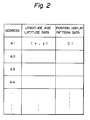
- a position registration data table in which a plurality of longitude and latitude data and the position display pattern data are stored as pairs at every address is formed in the RAM 9, as shown in Fig. 2.
- the position registration data table uses areas from an address A1 in the RAM 9.
- a CD-ROM for instance, is used as an external memory medium and is a non-volatile read only memory medium.
- the external memory medium is not limited to a CD-ROM but could also be another non-volatile memory medium such as a DAT, an IC card, or the like.
- map data which is obtained by converting each point of the roads on the map into digital values (numerical values)
- service list display data detailed display data, longitude and latitude data as position coordinate data, and position display pattern data, which will be explained hereinlater
- Memory information in the CD-ROM is read out by a CD-ROM drive 10.
- a read output of the CD-ROM drive 10 is decoded by a CD-ROM decoder 11 and sent to a bus line L.
- a vehicle power source voltage from a battery transmitted through what is called an accessory switch 12 of the vehicle is regulated by a regulator 13 and supplied as a power source to each section in the navigation apparatus.
- the power source which is supplied to the RAM 9 mentioned above is regulated by another regulator (not shown) different from the regulator 13 without passing through the accessory switch 12.
- the CPU 7 calculates the running direction of the vehicle on the basis of the output data of the direction sensor 1 at predetermined periods by timer interruption.
- the CPU 7 also obtains the longitude and latitude data as coordinate data of the present location of the vehicle from the running distance and the running direction by the interruption of every run of a predetermined distance based on the output data of the distance sensor 3.
- the CPU 7 collects the map data of the area of a predetermined size including the present position coordinates from the CD-ROM and temporarily stores the collected data into the RAM 9 and also supplies it to a display apparatus 16.
- the display apparatus 16 comprises: a display 17 such as a CRT or the like; a graphic memory 18 comprising a V (Video)-RAM or the like; a graphic controller 19 for drawing the map data sent from the system controller 5 as image data into the graphic memory 18 and for generating the image data; and a display controller 20 for controlling so as to display a map on the display 17 in accordance with the image data generated from the graphics controller 19.
- An input device 21 comprises a keyboard or the like and generates various kinds of commands or the like to the system controller 5 by the key operation of the user. Keys which are used in the above key operations include a selection key to switch the display content on the display 17, a position registration key to store data into the RAM 9 (all of the above keys are not shown), and the like.
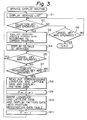
- the user registering operation which is executed by the CPU 7 will now be described in accordance with a service display routine shown as a flowchart in Fig. 3.
- the service display routine is accessed ad executed when the service display menu is selected by the key operation of the user on the input device 21 during the execution of the main routine (not shown).
- This routine is such that the present location of the vehicle is calculated on the basis of the output data of the sensors 1 and 3 and a group of map data of the area of a predetermined size including the present location of the vehicle is read out from the CD-ROM by the CPU 7 and supplied to the graphic controller 19 which writes it into the graphic memory 18 and then displayed on the display 17 as a map around the present location of the vehicle, and such that the vehicle position indicative of the present location of the vehicle is displayed on the map, and the like.
- the CPU 7 first displays the service list on the display 17 (step S1).
- the service list includes restaurants and hotels in each area.
- the CPU 7 reads out the service list display data recorded in the CD-ROM and supplies it to the graphic controller 19 and allows the content in the graphic memory 18 to be rewritten.
- the service list is displayed on the display 17.
- the names of the restaurants specialising in Japanese cuisine, French cuisine, Chinese cuisine, and the like are displayed on a unit (district) basis of the town or city.
- the user moves a cursor by the key operation of the input device 21 and operates the selection key.
- step S2 the CPU 7 determines whether the selection key has been operated or not (step S2).
- the CPU 7 gives a command to the CD-ROM drive 10 so as to read out the detailed display data from the CD-ROM in accordance with the cursor position when the selection key has been operated (step S3).
- the detailed display data regarding the restaurant selected from the service list is read out from the CD-ROM.
- the CPU 7 supplies the read-out detailed display data to the graphic controller 19 (step S4).
- the detailed information of the selected restaurant or the like is then displayed on the display 17.
- step S5 a check is made to see if the cancel key in the input device 21 has been operated or not.
- step S6 a check is made to see if the cancel key of the input device 21 has been operated or not (step S6).
- the processing routine is finished.
- step S7 a check is made to see whether or not the position registration key in the input device 21 has been operated.
- step S8 a command is given to the CD-ROM drive 10 in order to read out the longitude and latitude data and the position display pattern data corresponding to the read detailed display data from CD-ROM (step S8). "1" is added to the pointer P, which indicates the address of which data was last written (step S9).
- the read longitude and latitude data and position display pattern data are written as a data pair at the memory position (address) designated by the pointer P in the position registration data table in the RAM 9 (step S10).
- a position registration flag F is set to "1" (step S11).
- the pointer P shows the address of the memory position of the latest longitude and latitude data and position display pattern data to have been written at the present stage into the position registration data table in the RAM 9.
- the initial value just after the power source to the RAM 9 was turned on is set to, for example, A1.
- the longitude and latitude data is written as (x1, y1) and the position display pattern data is written as D1 at the memory location having the address A1.
- the position registering key when the position registering key is operated at the stage in which the information is displayed in detail on the display 17, the user position is registered. It is however, also possible to construct the apparatus of the present invention in a manner such that when the position registration key is operated at the stage in which the service list is displayed on the display 17, the user registration for the service facility such as a restaurant or the like at the cursor position is executed.
- the operation to display the registered position data on the display 17 which is executed by the CPU 7 will now be described in accordance with a registration position display routine shown as a flowchart in Fig. 4.
- the registration position display routine is executed as a subroutine in the above main routine.
- the CPU 7 first determines whether the position registration flag F has been set to 1 or not (step S21).
- F 0, this means that no longitude and latitude data and position display pattern data have been written into the position registration data table in the RAM 9, so the processing routine is finished.
- the longitude and latitude data (x n , y n ) are read out from the memory position designated by the address A n in the position registration data table (step S23).
- the position display pattern data D n is read out from the memory position of the address A n in the position registration data table (step S25).
- the longitude and latitude data (x n , y n ) and the position display pattern data D n are supplied to the graphic controller 19 (step S26) which writes the pattern data on the map data in the graphic memory 18 at the position corresponding to the longitude and latitude data.
- This mixed data in the graphic memory is read and supplied to the display controller 20 as image data by the graphic controller 19.
- the display pattern shown by the position display pattern data Dn is displayed on the display 17 at the position on the map indicated by the longitude and latitude data (x n , y n ). For instance, in the case of the restaurant a display pattern "R”, and in the case of the hotel a display pattern "H”, is displayed at the position on the map where such a restaurant or hotel exists.
- step S26 After execution of the step S26, "1" is added to the variable n (step S27) and a check is made to see if the address A n is larger than the pointer P or not (step S28). When A n >P, the processing routine is finished. When A n ⁇ P, step S23 follows and the above operations are executed for all of the data stored in the position registration data table.
- the restaurants and hotels have been mentioned as service facilities.
- the invention is not limited to them but can also register, for example, department stores, supermarkets, schools, and hospitals as service facilities.
- the display data indicative of a plurality of service facilities and the position coordinate data indicative of the existing positions of the service facilities have previously been stored into the first memory means, and merely by designating one of the plurality of service facilities displayed on the display by a key operation, the position coordinate data corresponding to the designated service facility is read out from the first memory means and registered as a user position into the second memory means. Accordingly, when the map is displayed on the display, the position coordinate data which has been registered as a user position and the corresponding pattern data is read out and mixed with the map data such that a predetermined pattern can be displayed on the map at the position indicated by the position coordinate data.
- the user position can, therefore, be registered by this simple operation, so that the positions of the service facilities such as restaurants or hotels which are necessary for each user can be easily confirmed on the displayed map.
Abstract
Description
- The invention relates to an on-board navigation apparatus which displays on a display a map to assist in the running of a vehicle.
- There is an on-board navigation apparatus in which map data, including road data which is obtained by converting each point of the roads on a map into numerical values, is stored in a memory medium such as a CD-ROM or the like. A group of map data of an area of a predetermined size including the present location, which has been previously determined, is read out from this memory medium and displayed on a display as a map around the present location of the vehicle. The vehicle position indicative of the present location of the vehicle is also automatically displayed on the map. Such an on-board navigation apparatus has been disclosed in, for instance, Japanese Provisional Patent Publication No. 63-12096 and has already been well known.
- Such an on-board navigation apparatus has not only a function to display the map of the area around the present location of the vehicle but also a user registering function such that the positions of service amenities such as restaurants, hotels, and the like, which have been registered by a user, existing in the area shown on the map are displayed as patterns on the map. According to the user registering function, a desired position is designated as a user position on the map by the key operation of the user. The longitude data and latitude data of the designated user positions are obtained from the map data. The display pattern to be used at such a position is selected by the user. The longitude and latitude data and the display pattern data are stored in the memory. When the map is displayed on the display screen, the longitude and latitude data and display pattern data existing in the range of the map are read out from the memory. The display pattern indicative of the restaurant or the like is displayed at the position indicated by the longitude and latitude data.
- In the conventional on-board navigation apparatus, however, in order to use the user registering function, the user activates the service mode and selects necessary service facilities, which are displayed on the display screen in the service mode, and memorizes the positions of these service facilities on the map. After completion of the service mode, the user can register such a position only by searching and designating the position on the navigation map. Consequently, very complicated operations are needed for such a registration.
- It is an object of the invention to provide an on-board navigation apparatus which can register a user position without requiring complicated operations.
- According to the invention, there is provided an on-board navigation apparatus to display a map on a display, comprising:
first memory means in which display data indicative of a plurality of service facilities and position coordinate data indicative of the positions of the service facilities have previously been stored;
means for reading out said display data from said first memory means and for displaying said plurality of service facilities onto said display in accordance with the read display data;
means for selectively designating one of said plurality of service facilities displayed on said display in accordance with an operator input;
means for reading out the position coordinate data corresponding to the designated service facility from said first memory means;
second memory means for storing the read position coordinate data;
means for reading out the stored position coordinate data from said second memory means when a map is displayed on said display; and
means for displaying a predetermined pattern on the map at the position indicated by the read position coordinate data from said second memory means. - In the on-board navigation apparatus of the invention, display data indicative of a plurality of service facilities and position coordinate data indicative of the existing positions of the service facilities are previously stored in the first memory means. By merely designating one of the plurality of service facilities displayed on the display by means of a user operation, the position coordinate data corresponding to the designated service facility is read out from the first memory means and registered as a user position into the second memory means. When the map is displayed on the display, therefore, the position coordinate data which has been registered as a user position and the corresponding pattern data is read out and mixed with the map data such that a predetermined pattern can be displayed on the map at the position indicated by the position coordinate data.
- An embodiment of the invention will now be described by way of example only and with reference to the accompanying drawings, in which:
- Fig. 1 is a block diagram showing an embodiment of the invention;
- Fig. 2 is a diagram showing a position registration data table;
- Fig. 3 is a flowchart showing a service display routine; and
- Fig. 4 is a flowchart showing a registration position display routine.
- Fig. 1 is a block diagram showing an embodiment of an on-board navigation apparatus according to the invention. In the on-board navigation apparatus, a
direction sensor 1 detects the running direction of the vehicle, anangular velocity sensor 2 detects an angular velocity of the vehicle, and adistance sensor 3 detects the distance of travel of the vehicle. A GPS (Global Positioning System) 4 determines the absolute position of the vehicle from longitude and latitude information or the like. Detection outputs from thesensors 1 to 3 and theGPS 4 are supplied to asystem controller 5. Thedirection sensor 1 is, for instance, a geomagnetism sensor to detect the running direction of the vehicle by earth magnetism (earth magnetic field). Thedistance sensor 3 comprises a pulse generator which generates a pulse for each rotation through a predetermined angle by the drive shaft (not shown) of the vehicle. The pulse generator magnetically or optically detects the rotational position of the drive shaft and generates a pulse and is well known. - The
system controller 5 comprises: aninterface 6 which receives the detection outputs of thesensors 1 to 4 and executes processes such as A/D (analog to digital) conversion and the like; a CPU (central processing unit) 7 for executing various image data processes and for calculating the running distance, running direction, present location coordinates (longitude, latitude), and the like of the vehicle on the basis of the output data from thesensors 1 to 4 which is sequentially sent from theinterface 6; a ROM (read only memory) 8 in which various kinds of processing programs of theCPU 7 and other necessary information have previously been written; and a RAM (random access memory) 9 into/from which information necessary to execute the programs is written and read out. TheRAM 9 is backed up by being supplied with a voltage from a battery (not shown) even when a power source of the navigation system is shut out so as not to extinguish the data such as longitude and latitude data, position display pattern data, position registration flag data, and the like, which will be explained later. A position registration data table in which a plurality of longitude and latitude data and the position display pattern data are stored as pairs at every address is formed in theRAM 9, as shown in Fig. 2. The position registration data table uses areas from an address A₁ in theRAM 9. - A CD-ROM, for instance, is used as an external memory medium and is a non-volatile read only memory medium. The external memory medium is not limited to a CD-ROM but could also be another non-volatile memory medium such as a DAT, an IC card, or the like. In addition to the map data which is obtained by converting each point of the roads on the map into digital values (numerical values), service list display data, detailed display data, longitude and latitude data as position coordinate data, and position display pattern data, which will be explained hereinlater, are also previously stored in the CD-ROM. Memory information in the CD-ROM is read out by a CD-ROM drive 10. A read output of the CD-ROM drive 10 is decoded by a CD-
ROM decoder 11 and sent to a bus line L. - A vehicle power source voltage from a battery transmitted through what is called an
accessory switch 12 of the vehicle is regulated by aregulator 13 and supplied as a power source to each section in the navigation apparatus. The power source which is supplied to theRAM 9 mentioned above is regulated by another regulator (not shown) different from theregulator 13 without passing through theaccessory switch 12. - When the vehicle is running, the
CPU 7 calculates the running direction of the vehicle on the basis of the output data of thedirection sensor 1 at predetermined periods by timer interruption. TheCPU 7 also obtains the longitude and latitude data as coordinate data of the present location of the vehicle from the running distance and the running direction by the interruption of every run of a predetermined distance based on the output data of thedistance sensor 3. TheCPU 7 collects the map data of the area of a predetermined size including the present position coordinates from the CD-ROM and temporarily stores the collected data into theRAM 9 and also supplies it to adisplay apparatus 16. - The
display apparatus 16 comprises: adisplay 17 such as a CRT or the like; agraphic memory 18 comprising a V (Video)-RAM or the like; agraphic controller 19 for drawing the map data sent from thesystem controller 5 as image data into thegraphic memory 18 and for generating the image data; and adisplay controller 20 for controlling so as to display a map on thedisplay 17 in accordance with the image data generated from thegraphics controller 19. Aninput device 21 comprises a keyboard or the like and generates various kinds of commands or the like to thesystem controller 5 by the key operation of the user. Keys which are used in the above key operations include a selection key to switch the display content on thedisplay 17, a position registration key to store data into the RAM 9 (all of the above keys are not shown), and the like. - The user registering operation which is executed by the
CPU 7 will now be described in accordance with a service display routine shown as a flowchart in Fig. 3. The service display routine is accessed ad executed when the service display menu is selected by the key operation of the user on theinput device 21 during the execution of the main routine (not shown). This routine is such that the present location of the vehicle is calculated on the basis of the output data of thesensors CPU 7 and supplied to thegraphic controller 19 which writes it into thegraphic memory 18 and then displayed on thedisplay 17 as a map around the present location of the vehicle, and such that the vehicle position indicative of the present location of the vehicle is displayed on the map, and the like. - In the service display routine, the
CPU 7 first displays the service list on the display 17 (step S1). The service list includes restaurants and hotels in each area. TheCPU 7 reads out the service list display data recorded in the CD-ROM and supplies it to thegraphic controller 19 and allows the content in thegraphic memory 18 to be rewritten. Thus, the service list is displayed on thedisplay 17. For instance, in the case of restaurants, the names of the restaurants specialising in Japanese cuisine, French cuisine, Chinese cuisine, and the like are displayed on a unit (district) basis of the town or city. In the case where the user wants to know further detailed information (locations, telephone numbers, menu, prices, and the like in the case of the restaurants) the user moves a cursor by the key operation of theinput device 21 and operates the selection key. After execution of step S1, theCPU 7 determines whether the selection key has been operated or not (step S2). When the selection key is operated, theCPU 7 gives a command to the CD-ROM drive 10 so as to read out the detailed display data from the CD-ROM in accordance with the cursor position when the selection key has been operated (step S3). For instance, the detailed display data regarding the restaurant selected from the service list is read out from the CD-ROM. TheCPU 7 supplies the read-out detailed display data to the graphic controller 19 (step S4). The detailed information of the selected restaurant or the like is then displayed on thedisplay 17. After execution of step S4, a check is made to see if the cancel key in theinput device 21 has been operated or not (step S5). When the cancel key of theinput device 21 is operated, the processing routine is returned to step S1. Also, when the selection key is not operated in step S2, a check is made to see if the cancel key of theinput device 21 has been operated or not (step S6). When the cancel key of theinput device 21 is operated, the processing routine is finished. - When the cancel key is not operated in step S5, a check is made to see whether or not the position registration key in the
input device 21 has been operated (step S7). When the position registration key is operated, a command is given to the CD-ROM drive 10 in order to read out the longitude and latitude data and the position display pattern data corresponding to the read detailed display data from CD-ROM (step S8). "1" is added to the pointer P, which indicates the address of which data was last written (step S9). The read longitude and latitude data and position display pattern data are written as a data pair at the memory position (address) designated by the pointer P in the position registration data table in the RAM 9 (step S10). A position registration flag F is set to "1" (step S11). The pointer P shows the address of the memory position of the latest longitude and latitude data and position display pattern data to have been written at the present stage into the position registration data table in theRAM 9. The initial value just after the power source to theRAM 9 was turned on is set to, for example, A₁. - As shown in Fig. 2, therefore, in the position registration data table, the longitude and latitude data is written as (x₁, y₁) and the position display pattern data is written as D₁ at the memory location having the address A₁.
- In the above user registering operation, when the position registering key is operated at the stage in which the information is displayed in detail on the
display 17, the user position is registered. It is however, also possible to construct the apparatus of the present invention in a manner such that when the position registration key is operated at the stage in which the service list is displayed on thedisplay 17, the user registration for the service facility such as a restaurant or the like at the cursor position is executed. - The operation to display the registered position data on the
display 17 which is executed by theCPU 7 will now be described in accordance with a registration position display routine shown as a flowchart in Fig. 4. The registration position display routine is executed as a subroutine in the above main routine. - In the registration position display routine, the
CPU 7 first determines whether the position registration flag F has been set to 1 or not (step S21). When F = 0, this means that no longitude and latitude data and position display pattern data have been written into the position registration data table in theRAM 9, so the processing routine is finished. When F = 1, this means that longitude and latitude data and position display pattern data have been written into the position registration data table in theRAM 9, and, therefore, a variable n is set to 1 (step S22). The longitude and latitude data (xn, yn) are read out from the memory position designated by the address An in the position registration data table (step S23). A check is made to see whether or not the longitude and latitude shown by the longitude and latitude data (xn, yn) lie within the range of the map displayed at present by the processes of the main routine (step S24). In the case of the longitude and latitude data (xn, yn) being within the range of the map which is at present being displayed, the position display pattern data Dn is read out from the memory position of the address An in the position registration data table (step S25). The longitude and latitude data (xn, yn) and the position display pattern data Dn are supplied to the graphic controller 19 (step S26) which writes the pattern data on the map data in thegraphic memory 18 at the position corresponding to the longitude and latitude data. This mixed data in the graphic memory is read and supplied to thedisplay controller 20 as image data by thegraphic controller 19. Thus the display pattern shown by the position display pattern data Dn is displayed on thedisplay 17 at the position on the map indicated by the longitude and latitude data (xn, yn). For instance, in the case of the restaurant a display pattern "R", and in the case of the hotel a display pattern "H", is displayed at the position on the map where such a restaurant or hotel exists. - After execution of the step S26, "1" is added to the variable n (step S27) and a check is made to see if the address An is larger than the pointer P or not (step S28). When An>P, the processing routine is finished. When An≦ P, step S23 follows and the above operations are executed for all of the data stored in the position registration data table.
- In the above embodiment, the restaurants and hotels have been mentioned as service facilities. The invention, however, is not limited to them but can also register, for example, department stores, supermarkets, schools, and hospitals as service facilities.
- In the on-board navigation apparatus of the invention, the display data indicative of a plurality of service facilities and the position coordinate data indicative of the existing positions of the service facilities have previously been stored into the first memory means, and merely by designating one of the plurality of service facilities displayed on the display by a key operation, the position coordinate data corresponding to the designated service facility is read out from the first memory means and registered as a user position into the second memory means. Accordingly, when the map is displayed on the display, the position coordinate data which has been registered as a user position and the corresponding pattern data is read out and mixed with the map data such that a predetermined pattern can be displayed on the map at the position indicated by the position coordinate data. The user position can, therefore, be registered by this simple operation, so that the positions of the service facilities such as restaurants or hotels which are necessary for each user can be easily confirmed on the displayed map.
Claims (2)
- An on-board navigation apparatus to display a map on a display (17), comprising:
first memory means (10) in which display data indicative of a plurality of service facilities and position coordinate data indicative of the positions of the service facilities have previously been stored;
means (6) for reading out said display data from said first memory means (10) and for displaying said plurality of service facilities onto said display (17) in accordance with the read display data;
means (21) for selectively designating one of said plurality of service facilities displayed on said display in accordance with an operator input;
means (7) for reading out the position coordinate data corresponding to the designated service facility from said first memory means;
second memory means (9) for storing the read position coordinate data;
means (7) for reading out the stored position coordinate data from said second memory means when a map is displayed on said display (17); and
means (19,20) for displaying a predetermined pattern on the map at the position indicated by the read position coordinate data from said second memory means (9). - An on-board navigation apparatus according to claim 1, wherein said second memory means (9) has a plurality of memory locations to store said position coordinate data and position display pattern data to indicate said predetermined pattern, as a pair.
Applications Claiming Priority (2)
| Application Number | Priority Date | Filing Date | Title |
|---|---|---|---|
| JP3079884A JP2891795B2 (en) | 1991-04-12 | 1991-04-12 | In-vehicle navigation device |
| JP79884/91 | 1991-04-12 |
Publications (3)
| Publication Number | Publication Date |
|---|---|
| EP0508787A2 true EP0508787A2 (en) | 1992-10-14 |
| EP0508787A3 EP0508787A3 (en) | 1993-02-24 |
| EP0508787B1 EP0508787B1 (en) | 1996-03-13 |
Family
ID=13702686
Family Applications (1)
| Application Number | Title | Priority Date | Filing Date |
|---|---|---|---|
| EP92303180A Expired - Lifetime EP0508787B1 (en) | 1991-04-12 | 1992-04-09 | On-board navigation apparatus |
Country Status (4)
| Country | Link |
|---|---|
| US (1) | US5424951A (en) |
| EP (1) | EP0508787B1 (en) |
| JP (1) | JP2891795B2 (en) |
| DE (1) | DE69208915T2 (en) |
Cited By (6)
| Publication number | Priority date | Publication date | Assignee | Title |
|---|---|---|---|---|
| EP0720003A1 (en) * | 1994-12-28 | 1996-07-03 | Aisin Aw Co., Ltd. | Navigation device |
| EP0766217A2 (en) * | 1995-09-29 | 1997-04-02 | Aisin Aw Co., Ltd. | Map indication device and navigation device |
| GB2353160A (en) * | 1999-06-02 | 2001-02-14 | Nicholas Gale | Automatic display of local information |
| US6385622B2 (en) * | 1995-01-11 | 2002-05-07 | W. Lincoln Bouve | System and methods for remotely accessing a selected group of items of interest from a database |
| GB2368990A (en) * | 2000-11-13 | 2002-05-15 | Iprox Ltd | Location dependent display of material |
| US7183942B2 (en) | 2000-01-26 | 2007-02-27 | Origin Technologies Limited | Speed trap detection and warning system |
Families Citing this family (43)
| Publication number | Priority date | Publication date | Assignee | Title |
|---|---|---|---|---|
| US10361802B1 (en) | 1999-02-01 | 2019-07-23 | Blanding Hovenweep, Llc | Adaptive pattern recognition based control system and method |
| US8352400B2 (en) | 1991-12-23 | 2013-01-08 | Hoffberg Steven M | Adaptive pattern recognition based controller apparatus and method and human-factored interface therefore |
| EP0775891B1 (en) * | 1992-02-18 | 1999-05-12 | Pioneer Electronic Corporation | Navigation apparatus with enhanced positional display function |
| US7064749B1 (en) | 1992-11-09 | 2006-06-20 | Adc Technology Inc. | Portable communicator |
| JPH06241821A (en) * | 1993-02-22 | 1994-09-02 | Sanyo Electric Co Ltd | Navigator for vehicle |
| US7049981B2 (en) | 1994-06-24 | 2006-05-23 | Navteq North America, Llc | Electronic navigation system and method |
| US5543789A (en) * | 1994-06-24 | 1996-08-06 | Shields Enterprises, Inc. | Computerized navigation system |
| US7432830B2 (en) * | 1994-06-24 | 2008-10-07 | Navteq North America, Llc | Electronic navigation system and method |
| US5648768A (en) * | 1994-12-30 | 1997-07-15 | Mapsys, Inc. | System and method for identifying, tabulating and presenting information of interest along a travel route |
| US6085177A (en) * | 1995-01-11 | 2000-07-04 | Civic-Ddi, Llc | Systems for accessing the internet and geo-defined data and associated methods |
| US5610822A (en) * | 1995-03-03 | 1997-03-11 | Trimble Navigation, Ltd. | Position-related multi-media presentation system |
| JPH09305108A (en) * | 1996-03-11 | 1997-11-28 | Denso Corp | Method and device for specifying location, and method and device for displaying map using them |
| US6202023B1 (en) | 1996-08-22 | 2001-03-13 | Go2 Systems, Inc. | Internet based geographic location referencing system and method |
| US20040139049A1 (en) | 1996-08-22 | 2004-07-15 | Wgrs Licensing Company, Llc | Unified geographic database and method of creating, maintaining and using the same |
| US5839088A (en) * | 1996-08-22 | 1998-11-17 | Go2 Software, Inc. | Geographic location referencing system and method |
| JP3798489B2 (en) * | 1997-01-14 | 2006-07-19 | 株式会社ザナヴィ・インフォマティクス | Car navigation system |
| US7268700B1 (en) | 1998-01-27 | 2007-09-11 | Hoffberg Steven M | Mobile communication device |
| US7904187B2 (en) | 1999-02-01 | 2011-03-08 | Hoffberg Steven M | Internet appliance system and method |
| DE19956112A1 (en) * | 1999-11-22 | 2001-05-23 | Mannesmann Vdo Ag | Navigation system with improved object selection |
| JP2001153665A (en) * | 1999-11-25 | 2001-06-08 | Pioneer Electronic Corp | Navigation device for mobile body |
| WO2001054021A1 (en) * | 2000-01-18 | 2001-07-26 | Richard Liming | System and method providing a spatial location context |
| US6871140B1 (en) | 2000-02-25 | 2005-03-22 | Costar Group, Inc. | System and method for collection, distribution, and use of information in connection with commercial real estate |
| US6810323B1 (en) | 2000-09-25 | 2004-10-26 | Motorola, Inc. | System and method for storing and using information associated with geographic locations of interest to a mobile user |
| US7487114B2 (en) * | 2000-10-23 | 2009-02-03 | Costar Group, Inc. | System and method for associating aerial images, map features, and information |
| US7640204B2 (en) | 2000-10-23 | 2009-12-29 | Costar Group, Inc. | System and method for collection, distribution, and use of information in connection with commercial real estate |
| US20090132316A1 (en) * | 2000-10-23 | 2009-05-21 | Costar Group, Inc. | System and method for associating aerial images, map features, and information |
| US7174301B2 (en) * | 2000-10-23 | 2007-02-06 | Costar Group, Inc. | System and method for accessing geographic-based data |
| US7076452B2 (en) * | 2000-10-23 | 2006-07-11 | Costar Group, Inc. | System and method for collection, distribution, and use of information in connection with commercial real estate |
| US6493630B2 (en) * | 2001-02-16 | 2002-12-10 | Wizeguides.Com Inc. | Bundled map guide |
| US6735520B2 (en) * | 2001-03-13 | 2004-05-11 | Pioneer Corporation | Map information providing method, map information providing system, and recording medium on which the method programed is recorded |
| US6661353B1 (en) | 2001-03-15 | 2003-12-09 | Matsushita Avionics Systems Corporation | Method for displaying interactive flight map information |
| JP2003173237A (en) * | 2001-09-28 | 2003-06-20 | Ricoh Co Ltd | Information input-output system, program and storage medium |
| EP1437571B1 (en) * | 2001-10-16 | 2012-06-20 | Panasonic Corporation | Terminal apparatus |
| US6662116B2 (en) * | 2001-11-30 | 2003-12-09 | Exxonmobile Research And Engineering Company | Method for analyzing an unknown material as a blend of known materials calculated so as to match certain analytical data and predicting properties of the unknown based on the calculated blend |
| US7126580B2 (en) * | 2002-06-13 | 2006-10-24 | Panasonic Automotive Systems Company Of America | Interface for a multifunctional system |
| US9818136B1 (en) | 2003-02-05 | 2017-11-14 | Steven M. Hoffberg | System and method for determining contingent relevance |
| CA2576278A1 (en) * | 2004-05-17 | 2005-11-24 | Spatial Data Analytics Corporation | Communication system and method for comprehensive collection, aggregation and dissemination of geospatial information |
| FR2920580B1 (en) * | 2007-08-31 | 2010-09-03 | Thales Sa | METHOD FOR SIMPLIFYING THE DISPLAY OF STATIONARY ELEMENTS OF AN EMBEDDED DATA BASE |
| US8249805B2 (en) * | 2008-12-12 | 2012-08-21 | Alpine Electronics, Inc. | Automatic updating of favorite places for navigation system upon change of home address |
| CN102461118B (en) | 2009-06-11 | 2016-07-06 | 松下航空电子公司 | For providing the system and method for safety on a mobile platform |
| US8704960B2 (en) | 2010-04-27 | 2014-04-22 | Panasonic Avionics Corporation | Deployment system and method for user interface devices |
| JP6387782B2 (en) * | 2014-10-17 | 2018-09-12 | ソニー株式会社 | Control device, control method, and computer program |
| USD959552S1 (en) | 2021-07-21 | 2022-08-02 | Speedfind, Inc | Display sign |
Citations (1)
| Publication number | Priority date | Publication date | Assignee | Title |
|---|---|---|---|---|
| US4761742A (en) * | 1985-04-26 | 1988-08-02 | Nippondenso Co., Ltd. | Guiding spot display apparatus |
Family Cites Families (5)
| Publication number | Priority date | Publication date | Assignee | Title |
|---|---|---|---|---|
| JPH07113999B2 (en) * | 1986-07-02 | 1995-12-06 | パイオニア株式会社 | Vehicle location recognition method |
| JPH0616320B2 (en) * | 1987-04-08 | 1994-03-02 | 株式会社日立製作所 | Vehicle driving guide device and method |
| NL8702087A (en) * | 1987-09-04 | 1989-04-03 | Philips Nv | VEHICLE NAVIGATION DEVICE WITH DISPLAY OF A SELECTED MAP ELEMENT ACCORDING TO A PRE-DEFINED REPRESENTATION STANDARD. |
| JP2613232B2 (en) * | 1987-12-28 | 1997-05-21 | アイシン・エィ・ダブリュ株式会社 | Vehicle navigation system |
| US4974170A (en) * | 1988-01-21 | 1990-11-27 | Directional Data, Inc. | Electronic directory for identifying a selected group of subscribers |
-
1991
- 1991-04-12 JP JP3079884A patent/JP2891795B2/en not_active Expired - Lifetime
-
1992
- 1992-03-27 US US07/858,852 patent/US5424951A/en not_active Expired - Lifetime
- 1992-04-09 DE DE69208915T patent/DE69208915T2/en not_active Expired - Lifetime
- 1992-04-09 EP EP92303180A patent/EP0508787B1/en not_active Expired - Lifetime
Patent Citations (1)
| Publication number | Priority date | Publication date | Assignee | Title |
|---|---|---|---|---|
| US4761742A (en) * | 1985-04-26 | 1988-08-02 | Nippondenso Co., Ltd. | Guiding spot display apparatus |
Non-Patent Citations (2)
| Title |
|---|
| VNIS `89 Conference Record, 11-13 Septem- ber 1989, Toronto, Canada, D.L.Frank : "Information Systems: An Integral Part of Future Vehicles", pages 85-88 * |
| VNIS `89 Conference Record, 11-13 Septem- ber 1989, Toronto, Canada, T.Saito et al.: "Automobile Navigation System Using Beacon Information", pages 139-145 * |
Cited By (11)
| Publication number | Priority date | Publication date | Assignee | Title |
|---|---|---|---|---|
| EP0720003A1 (en) * | 1994-12-28 | 1996-07-03 | Aisin Aw Co., Ltd. | Navigation device |
| US6385622B2 (en) * | 1995-01-11 | 2002-05-07 | W. Lincoln Bouve | System and methods for remotely accessing a selected group of items of interest from a database |
| US6408307B1 (en) * | 1995-01-11 | 2002-06-18 | Civix-Ddi, Llc | System and methods for remotely accessing a selected group of items of interest from a database |
| US6415291B2 (en) * | 1995-01-11 | 2002-07-02 | Civix-Ddi, Llc | System and methods for remotely accessing a selected group of items of interest from a database |
| US8296335B2 (en) | 1995-01-11 | 2012-10-23 | Civix-Ddi, Llc | Method for advertising information |
| EP0766217A2 (en) * | 1995-09-29 | 1997-04-02 | Aisin Aw Co., Ltd. | Map indication device and navigation device |
| EP0766217A3 (en) * | 1995-09-29 | 1998-08-19 | Aisin Aw Co., Ltd. | Map indication device and navigation device |
| KR100235239B1 (en) * | 1995-09-29 | 1999-12-15 | 모리 하루오 | Building shape output apparatus and method thereof, map display apparauts and method thereof, and navigation apparatus and method thereof |
| GB2353160A (en) * | 1999-06-02 | 2001-02-14 | Nicholas Gale | Automatic display of local information |
| US7183942B2 (en) | 2000-01-26 | 2007-02-27 | Origin Technologies Limited | Speed trap detection and warning system |
| GB2368990A (en) * | 2000-11-13 | 2002-05-15 | Iprox Ltd | Location dependent display of material |
Also Published As
| Publication number | Publication date |
|---|---|
| DE69208915T2 (en) | 1996-08-01 |
| JP2891795B2 (en) | 1999-05-17 |
| EP0508787B1 (en) | 1996-03-13 |
| EP0508787A3 (en) | 1993-02-24 |
| DE69208915D1 (en) | 1996-04-18 |
| JPH04314084A (en) | 1992-11-05 |
| US5424951A (en) | 1995-06-13 |
Similar Documents
| Publication | Publication Date | Title |
|---|---|---|
| EP0508787B1 (en) | On-board navigation apparatus | |
| US5270936A (en) | Simplified navigation apparatus | |
| US6040824A (en) | Information display system with touch panel | |
| US6567744B1 (en) | In-vehicle navigation apparatus | |
| US7869938B2 (en) | Method and apparatus for displaying simplified map image for navigation system | |
| US5925091A (en) | Method and apparatus for drawing a map for a navigation system | |
| EP0773525B1 (en) | Navigation apparatus for a vehicle taking into account the road width | |
| EP0772173B1 (en) | Information guidance system based on structure configuration map | |
| US5337244A (en) | On-board navigation apparatus | |
| US6895331B2 (en) | Navigation device and method | |
| US6445999B1 (en) | Navigation system and method of displaying a quasi-three-dimensional map information | |
| US20020130906A1 (en) | Point-of interest icon and point-of- interest mark display method | |
| US7665040B2 (en) | Information processing apparatus utilizing real image data | |
| EP2275779B1 (en) | Automotive navigation system | |
| JP3893325B2 (en) | Input display device and input display method | |
| JP2001141504A (en) | Information display | |
| JPH08145702A (en) | Map display device | |
| JPH04283788A (en) | Course guiding device for vehicle | |
| JP3278897B2 (en) | Navigation system for moving objects | |
| EP1134553A2 (en) | In-Vehicle navigation apparatus | |
| JP3191629B2 (en) | Travel position display device | |
| JP2002039769A (en) | Navigation system | |
| JPH02141611A (en) | Route guide apparatus for vehicle | |
| JPH06139494A (en) | Map plotting method for on-vehicle navigator | |
| JP2000337913A (en) | Spot name obtaining method and equipment in navigation equipment |
Legal Events
| Date | Code | Title | Description |
|---|---|---|---|
| PUAI | Public reference made under article 153(3) epc to a published international application that has entered the european phase |
Free format text: ORIGINAL CODE: 0009012 |
|
| AK | Designated contracting states |
Kind code of ref document: A2 Designated state(s): DE FR GB |
|
| PUAL | Search report despatched |
Free format text: ORIGINAL CODE: 0009013 |
|
| AK | Designated contracting states |
Kind code of ref document: A3 Designated state(s): DE FR GB |
|
| 17P | Request for examination filed |
Effective date: 19930602 |
|
| 17Q | First examination report despatched |
Effective date: 19941102 |
|
| GRAA | (expected) grant |
Free format text: ORIGINAL CODE: 0009210 |
|
| AK | Designated contracting states |
Kind code of ref document: B1 Designated state(s): DE FR GB |
|
| REF | Corresponds to: |
Ref document number: 69208915 Country of ref document: DE Date of ref document: 19960418 |
|
| ET | Fr: translation filed | ||
| PLBE | No opposition filed within time limit |
Free format text: ORIGINAL CODE: 0009261 |
|
| STAA | Information on the status of an ep patent application or granted ep patent |
Free format text: STATUS: NO OPPOSITION FILED WITHIN TIME LIMIT |
|
| 26N | No opposition filed | ||
| REG | Reference to a national code |
Ref country code: GB Ref legal event code: 746 Effective date: 19970307 |
|
| REG | Reference to a national code |
Ref country code: FR Ref legal event code: D6 |
|
| REG | Reference to a national code |
Ref country code: GB Ref legal event code: IF02 |
|
| PGFP | Annual fee paid to national office [announced via postgrant information from national office to epo] |
Ref country code: FR Payment date: 20110426 Year of fee payment: 20 Ref country code: DE Payment date: 20110406 Year of fee payment: 20 |
|
| PGFP | Annual fee paid to national office [announced via postgrant information from national office to epo] |
Ref country code: GB Payment date: 20110406 Year of fee payment: 20 |
|
| REG | Reference to a national code |
Ref country code: DE Ref legal event code: R071 Ref document number: 69208915 Country of ref document: DE |
|
| REG | Reference to a national code |
Ref country code: DE Ref legal event code: R071 Ref document number: 69208915 Country of ref document: DE |
|
| REG | Reference to a national code |
Ref country code: GB Ref legal event code: PE20 Expiry date: 20120408 |
|
| PG25 | Lapsed in a contracting state [announced via postgrant information from national office to epo] |
Ref country code: DE Free format text: LAPSE BECAUSE OF EXPIRATION OF PROTECTION Effective date: 20120410 |
|
| PG25 | Lapsed in a contracting state [announced via postgrant information from national office to epo] |
Ref country code: GB Free format text: LAPSE BECAUSE OF EXPIRATION OF PROTECTION Effective date: 20120408 |