EP0505815A2 - Coil tubing electrical cable for well pumping system - Google Patents
Coil tubing electrical cable for well pumping system Download PDFInfo
- Publication number
- EP0505815A2 EP0505815A2 EP92104025A EP92104025A EP0505815A2 EP 0505815 A2 EP0505815 A2 EP 0505815A2 EP 92104025 A EP92104025 A EP 92104025A EP 92104025 A EP92104025 A EP 92104025A EP 0505815 A2 EP0505815 A2 EP 0505815A2
- Authority
- EP
- European Patent Office
- Prior art keywords
- conductors
- cable
- electrical
- insulated
- well
- Prior art date
- Legal status (The legal status is an assumption and is not a legal conclusion. Google has not performed a legal analysis and makes no representation as to the accuracy of the status listed.)
- Withdrawn
Links
Images
Classifications
-
- E—FIXED CONSTRUCTIONS
- E21—EARTH DRILLING; MINING
- E21B—EARTH DRILLING, e.g. DEEP DRILLING; OBTAINING OIL, GAS, WATER, SOLUBLE OR MELTABLE MATERIALS OR A SLURRY OF MINERALS FROM WELLS
- E21B17/00—Drilling rods or pipes; Flexible drill strings; Kellies; Drill collars; Sucker rods; Cables; Casings; Tubings
- E21B17/20—Flexible or articulated drilling pipes, e.g. flexible or articulated rods, pipes or cables
- E21B17/206—Flexible or articulated drilling pipes, e.g. flexible or articulated rods, pipes or cables with conductors, e.g. electrical, optical
-
- H—ELECTRICITY
- H01—ELECTRIC ELEMENTS
- H01B—CABLES; CONDUCTORS; INSULATORS; SELECTION OF MATERIALS FOR THEIR CONDUCTIVE, INSULATING OR DIELECTRIC PROPERTIES
- H01B7/00—Insulated conductors or cables characterised by their form
- H01B7/0072—Electrical cables comprising fluid supply conductors
-
- H—ELECTRICITY
- H01—ELECTRIC ELEMENTS
- H01B—CABLES; CONDUCTORS; INSULATORS; SELECTION OF MATERIALS FOR THEIR CONDUCTIVE, INSULATING OR DIELECTRIC PROPERTIES
- H01B7/00—Insulated conductors or cables characterised by their form
- H01B7/16—Rigid-tube cables
Definitions
- the cause of z-kinking in electromechanical cables exposed to tensile and compressive forces and elevated temperatures stem from the high coefficient of thermal expansion of the electrical conductors (typically copper or aluminum) versus the tensile supporting member (typically steel) which leads to compressive loading of the conductors.
- the present invention is directed to a solution to this problem by controlling the elongation of the metal components of the electrical cable to allow optimum performance under tensile load and at elevated temperatures.
- the present invention is directed to an electrical motor operated well pump system for use in a well which includes an electrical cable adapted to be connected to the motor.
- the cable includes a plurality of insulated electrical conductors enclosed in a low tensile strength corrosion-resistant metal tubing.
- the twist factor or lay length of the conductors is approximately eight to fourteen times the diameter of the insulated conductors in order to minimize the tendency for the conductors to Z-kink.
- the lay length is approximately ten times the diameter of the insulated conductors.
- the electrical cable includes one or more hydraulic tubes extending through the cable interiorly of the metal tubing for control of other well equipment.
- the reference numeral 10 generally indicates a submersible well pumping system of the present invention which is to be installed in a well casing 12 beneath a wellhead 14.
- the system is installed in the casing 12 and generally includes an electrical motor 16 which supplies rotational energy for a downhole pump 18.
- a motor protector 20 helps to isolate the motor 16 from mechanical vibrations and well fluids.
- a motor connector 21 provides a connection between the motor 16 and an electrical supply.
- the pumping system 10 is lowered into the well casing 12 using an electrical cable 22 and attaches to the motor connector 21.
- the pumping system 10 is lowered until reaching a prepositioned shoe 24 which is positioned in the casing 12 and the pumping system 10 is latched into the shoe 24.
- the shoe 24 also serves to separate the pump intake 26 and the pump discharge 28 sections.
- Produced well fluid is pumped up the annulus 30 to the wellhead 14.
- the above description of a well pumping system is known.
- the preferred embodiment of the electrical cable 22 is best seen and is comprised of a plurality of electrical conductors 32, preferably copper, although aluminum is satisfactory.
- the electrical conductors 32 are preferably of a stranded wire to allow flexibility when twisting two or more of the insulated conductors together.
- the electrical conductors 32 are surrounded by a primary insulation 34 and the conductors 32 and insulation 34 are enclosed within a jacket 36 which serves to protect the insulated conductors during manufacture and enclosing within an outer metallic tube 38.
- the insulation 34 may be ethylene propylene compound designed for operating in temperatures up to 400° F.
- the jacket material 38 is also an ethylene propylene compound with a 400° F. rating.
- the insulation 34 may be of propylene thermoplastic and the jacket 36 may be of a high density polyethylene. This second embodiment may be used in shallow wells with low bottom hole temperatures.
- the insulation 34 may be of polyetheretherketone thermoplastic and the jacket 36 is of fluorinated elastomer such as sold under the trademark "Aflas.” This third embodiment construction is useful in wells with high bottom hole temperatures.
- the outer metallic tube 38 is preferably made of a standard low tensile strength, low alloy steel, such as ASTM A606, which is welded inline with the electrical power conductors 32, their insulation 34 and swedged over the core jacket 36 for a mechanical grip and to prevent well gases from migrating up the cable core.
- the forming of the metallic tube 38 is done in two separate sections: preforming a C-shape in a first section allowing placement of the cable core, and a second forming section is used to close the circle for welding.
- a low heat welding technique such as TIG welding is used to minimize damage to the jacket 36 material.
- the strength of the outer metal tube 38 will support its own weight, the cable core weight consisting of the conductors 32, insulation 34, and jacket 36, as well as the pump system of the motor 16 and pump 18 and connected equipment up to practical oilwell depths.
- the yield strength of the outer metal tube 38 will provide an adequate safety margin to allow for corrosion and added strength to release the well pumping system 10 during retrieval. While, of course, high tensile strength metallic tubing 38 could be used, it is generally not preferred, as it is less corrosion resistant. And, of course, if because of an extremely deep well, the strength of the outer metal tube 38 is not sufficient, additional support members (not shown) can be connected to the motor and pump assembly for support.
- one or more stainless steel hydraulic tubes 40 may be used extending through the interior of the cable 22 interiorly of the metal tubing 38 to provide hydraulic control of other well equipment, as will be discussed more fully hereinafter, or to provide a well treatment capability.
- the hydraulic tubes 40 may be omitted if not needed.
- the present invention is directed to overcome the problem of tensile load and elevated temperatures. Specifically, the difference in elongation of the two metal components, the electrical conductors 32 and the metallic coil tube 38 are closely designed to allow optimum performance.
- the elongation of the coil tube 38 may be controlled with the wall thickness used.
- Design constraints for the outer metallic tube 38 include: core weight, coil tube material weight, submersible pumping unit weight, and maximum operating temperature.
- Design constraints for the cable core include: maximum cable elongation, conductor size, insulated conductor twist factor and maximum operating temperature.
- the elongation of the electrical conductors 32 is maintained below the materials ultimate yield at the cable maximum load by varying the twist factor or twist lay length which is the length for one of the conductors to twist one revolution or 360°.
- the twist lay length has been reduced to allow the conductors 32 to act more as a spring when subjected to tensile and compressive forces encountered in normal operation.
- the lay length L (Fig. 3) should be eight to fourteen times the diameter D of an insulated conductor 32.
- the lay length is ten times the insulated conductor diameter.
- lay angle of conductors is at higher angle to axis of cable, the tensile and compressive forces are expressed in the elastomer core (as a spring) rather than in forcing the conductors to deform radially (forming z-kinks when compressed).
- the following parameters have been calculated to provide a satisfactory system in a well in which the pumping unit 10 has been installed at a depth of 6500 feet and the weight of the pumping unit is 3200 pounds at a maximum operating temperature of 400 F.
- the metallic coil tube 38 had a wall thickness of .080 inches, the core weight was 1.23 lbs/ft, and the coil tube 38 material weight was 0.99 lbs/ft.
- the maximum cable elongation was 0.20%, with an insulated copper twist factor of 10.
- the preferred release mechanism is by use of one or more calibrated shear pins 42 which are set to break at an adequate level below that of the outer metal tube 38 yield strength.
- a shear pin 42 is set into the shoe 24 by a spring 44 following removal of a pin cover 46 which is slidably moved out of engagement with the shear pin 42 when the cover 46 comes in contact with the shoe 24.
- other and different release mechanisms can be utilized.
- FIG. 5 another embodiment is shown in which the pumping unit 10a is set in a well in a casing 12a without requiring the use of the conventional shoe.
- a hydraulically set well packer 50 which may be actuated by one or more of the hydraulic lines 40 is connected to the pumping system 10a. Actuation of the packer 50 into engagement with the casing 12a provides ease in setting and releasing the pumping unit 10a from the casing 12a.
Abstract
Description
- It is known to utilize an electrical cable to supply electrical energy to a downhole motor which drives a pump for producing oil or water from a well. In addition, U.S. Patents Nos. 4,346,256 and 4,665,281 disclose the use of insulated electrical conductors enclosed in a metallic tube for supplying electrical power to a well pump.
- However, the prior art has not recognized or has been directed to the effect that tensile loads and high temperatures will have on the relative motion of the inner electrical conductors to the outer metallic tube. Insulation and jacket materials allow higher modulus materials, such as copper or aluminum, to easily elongate or even yield the insulation, such as elastomers. This condition is exacerbated over the longer lengths typically encountered in water and oilwells. The primary failure mechanism in electromechanical well cables is conductor "z-kinking" whereby the electrical conductors will twist radially leading to electrical failure. Another term for z-kinking is called birdcaging and is defined as the permanent deflection of a wire rope forced into compression. The cause of z-kinking in electromechanical cables exposed to tensile and compressive forces and elevated temperatures stem from the high coefficient of thermal expansion of the electrical conductors (typically copper or aluminum) versus the tensile supporting member (typically steel) which leads to compressive loading of the conductors.
- The present invention is directed to a solution to this problem by controlling the elongation of the metal components of the electrical cable to allow optimum performance under tensile load and at elevated temperatures.
- The present invention is directed to an electrical motor operated well pump system for use in a well which includes an electrical cable adapted to be connected to the motor. The cable includes a plurality of insulated electrical conductors enclosed in a low tensile strength corrosion-resistant metal tubing. The twist factor or lay length of the conductors is approximately eight to fourteen times the diameter of the insulated conductors in order to minimize the tendency for the conductors to Z-kink. Preferably, the lay length is approximately ten times the diameter of the insulated conductors.
- Still a further object of the present invention is wherein the electrical cable includes one or more hydraulic tubes extending through the cable interiorly of the metal tubing for control of other well equipment.
- Other and further objects, features and advantages will be apparent from the following description of a presently preferred embodiment of the invention, given for the purpose of disclosure and taken in conjunction with the accompanying drawings.
-
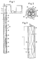
- Fig. 1 is an elevational schematic view of a submersible pumping system using the present invention,
- Fig. 2 is an enlarged, cross-sectional view of the electrical cable connected to the motor and the pump of Fig. 1,
- Fig. 3. is a cut-away elevational view, partly in cross section, illustrating the twist or lay length of the electrical conductor of Fig. 2,
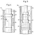
- Fig. 4 is a fragmentary elevational view, partly schematic, illustrating the connection of the motor and pump in the well, and
- Fig. 5 is an enlarged fragmentary elevational view of another method for setting the motor and pump in a well.
- Referring now to the drawings, and particularly to Fig. 1, the
reference numeral 10 generally indicates a submersible well pumping system of the present invention which is to be installed in awell casing 12 beneath awellhead 14. The system is installed in thecasing 12 and generally includes anelectrical motor 16 which supplies rotational energy for adownhole pump 18. Amotor protector 20 helps to isolate themotor 16 from mechanical vibrations and well fluids. Amotor connector 21 provides a connection between themotor 16 and an electrical supply. Thepumping system 10 is lowered into thewell casing 12 using anelectrical cable 22 and attaches to themotor connector 21. Thepumping system 10 is lowered until reaching aprepositioned shoe 24 which is positioned in thecasing 12 and thepumping system 10 is latched into theshoe 24. Theshoe 24 also serves to separate thepump intake 26 and thepump discharge 28 sections. Produced well fluid is pumped up theannulus 30 to thewellhead 14. Generally, the above description of a well pumping system is known. - Referring now to Fig. 2, the preferred embodiment of the
electrical cable 22 is best seen and is comprised of a plurality ofelectrical conductors 32, preferably copper, although aluminum is satisfactory. Theelectrical conductors 32 are preferably of a stranded wire to allow flexibility when twisting two or more of the insulated conductors together. - The
electrical conductors 32 are surrounded by aprimary insulation 34 and theconductors 32 andinsulation 34 are enclosed within ajacket 36 which serves to protect the insulated conductors during manufacture and enclosing within an outermetallic tube 38. In one embodiment, theinsulation 34 may be ethylene propylene compound designed for operating in temperatures up to 400° F. In this embodiment, thejacket material 38 is also an ethylene propylene compound with a 400° F. rating. In another embodiment, theinsulation 34 may be of propylene thermoplastic and thejacket 36 may be of a high density polyethylene. This second embodiment may be used in shallow wells with low bottom hole temperatures. In still a further embodiment, theinsulation 34 may be of polyetheretherketone thermoplastic and thejacket 36 is of fluorinated elastomer such as sold under the trademark "Aflas." This third embodiment construction is useful in wells with high bottom hole temperatures. - The outer
metallic tube 38 is preferably made of a standard low tensile strength, low alloy steel, such as ASTM A606, which is welded inline with theelectrical power conductors 32, theirinsulation 34 and swedged over thecore jacket 36 for a mechanical grip and to prevent well gases from migrating up the cable core. The forming of themetallic tube 38 is done in two separate sections: preforming a C-shape in a first section allowing placement of the cable core, and a second forming section is used to close the circle for welding. A low heat welding technique such as TIG welding is used to minimize damage to thejacket 36 material. Preferably, the strength of theouter metal tube 38 will support its own weight, the cable core weight consisting of theconductors 32,insulation 34, andjacket 36, as well as the pump system of themotor 16 andpump 18 and connected equipment up to practical oilwell depths. The yield strength of theouter metal tube 38 will provide an adequate safety margin to allow for corrosion and added strength to release the wellpumping system 10 during retrieval. While, of course, high tensile strengthmetallic tubing 38 could be used, it is generally not preferred, as it is less corrosion resistant. And, of course, if because of an extremely deep well, the strength of theouter metal tube 38 is not sufficient, additional support members (not shown) can be connected to the motor and pump assembly for support. - As shown in Fig. 2, if desired, one or more stainless steel
hydraulic tubes 40 may be used extending through the interior of thecable 22 interiorly of themetal tubing 38 to provide hydraulic control of other well equipment, as will be discussed more fully hereinafter, or to provide a well treatment capability. However, thehydraulic tubes 40 may be omitted if not needed. - However, as indicated while coil tubing electrical cable systems have been proposed in the past, they have not been directed to the problem of how to overcome the effects of tensile loads and high temperatures on the relative motion of the
inner conductors 32 relative to the outermetallic tube 38. The primary failure mechanism in electrical cables such ascable 22 has been z-kinking of theelectrical conductors 32 because of high elongation when theelectromechanical cable 22 is under tension followed by compression due to higher thermal expansion of the conductors 32 (and higher temperature due to resistant heating) compared to themetallic tube 38. For example, the coefficient of thermal expansion of copper is 16.E-6 in/in/deg. C., of aluminum is 23.E-6 in/in/deg. C., and of steel is 12-E in/in/deg. C. Thus, theconductors 32 of either copper or aluminum will tend to kink or loop on itself at intervals along thecable 22 during increased temperature changes which results in cable failure. - The present invention is directed to overcome the problem of tensile load and elevated temperatures. Specifically, the difference in elongation of the two metal components, the
electrical conductors 32 and themetallic coil tube 38 are closely designed to allow optimum performance. The elongation of thecoil tube 38 may be controlled with the wall thickness used. Design constraints for the outermetallic tube 38 include: core weight, coil tube material weight, submersible pumping unit weight, and maximum operating temperature. Design constraints for the cable core include: maximum cable elongation, conductor size, insulated conductor twist factor and maximum operating temperature. The elongation of theelectrical conductors 32 is maintained below the materials ultimate yield at the cable maximum load by varying the twist factor or twist lay length which is the length for one of the conductors to twist one revolution or 360°. In the present invention, to minimize the tendency of theelectrical conductors 32 to Z-kink, the twist lay length has been reduced to allow theconductors 32 to act more as a spring when subjected to tensile and compressive forces encountered in normal operation. In the present invention, it has been calculated that the lay length L (Fig. 3) should be eight to fourteen times the diameter D of aninsulated conductor 32. Preferably, the lay length is ten times the insulated conductor diameter. The effect of reducing the lay length L of theconductors 32 in effect increases the overall length of theconductors 32 and makes the difference in the coefficient of thermal expansion between theconductors 32 and thecoil tubing 38 less significant. Because lay angle of conductors is at higher angle to axis of cable, the tensile and compressive forces are expressed in the elastomer core (as a spring) rather than in forcing the conductors to deform radially (forming z-kinks when compressed). - As an example only, the following parameters have been calculated to provide a satisfactory system in a well in which the
pumping unit 10 has been installed at a depth of 6500 feet and the weight of the pumping unit is 3200 pounds at a maximum operating temperature of 400 F. For example, themetallic coil tube 38 had a wall thickness of .080 inches, the core weight was 1.23 lbs/ft, and thecoil tube 38 material weight was 0.99 lbs/ft. For copper twistedconductors 32 of a size #1 ANG, the maximum cable elongation was 0.20%, with an insulated copper twist factor of 10. - To retrieve the
submersible pumping system 10, the preferred release mechanism, as best seen in Fig. 4, is by use of one or more calibrated shear pins 42 which are set to break at an adequate level below that of theouter metal tube 38 yield strength. Ashear pin 42 is set into theshoe 24 by aspring 44 following removal of apin cover 46 which is slidably moved out of engagement with theshear pin 42 when thecover 46 comes in contact with theshoe 24. Of course, other and different release mechanisms can be utilized. - Referring now to Fig. 5, another embodiment is shown in which the
pumping unit 10a is set in a well in acasing 12a without requiring the use of the conventional shoe. In this case, a hydraulically set wellpacker 50, which may be actuated by one or more of thehydraulic lines 40 is connected to thepumping system 10a. Actuation of thepacker 50 into engagement with thecasing 12a provides ease in setting and releasing thepumping unit 10a from thecasing 12a. - The present invention, therefore, is well adapted to carry out the objects and attain the ends and advantages mentioned as well as others inherent therein. While presently preferred embodiments of the invention have been given for the purpose of disclosure, numerous changes in the details of construction, and arrangement of parts, will be readily apparent to those skilled in the art and which are encompassed within the spirit of the invention and the scope of the appended claims.
Claims (6)
- An electrical motor operated well pumping system for use in a well comprising,
an electrical cable adapted to be connected to the motor, said cable having a plurality of insulated electrical conductors having a diameter and which are twisted to have a lay length and which are enclosed in a low tensile strength corrosion-resistant metal tubing, and
said lay length of the conductors is approximately eight to fourteen times the diameter of the insulated conductors. - The system of claim 1 wherein,
said lay length is approximately ten times the diameter of the insulated conductors. - The system of claim 1 wherein the electrical cable includes,
one or more hydraulic tubes extending through the cable interiorly of the metal tubing. - An electrical cable comprising,
a cable having a plurality of insulated electrical conductors having a diameter and which are twisted to have a lay length and which are enclosed in a low tensile strength corrosion-resistant metal tubing, and said lay length of the conductors is approximately 8 to 14 times the diameter of the insulated conductors. - The cable of claim 4 wherein said lay length is approximately 10 times the diameter of the insulated conductors.
- The cable of claim 4 wherein the electrical cable includes one or more hydraulic tubes extending through the cable interiorly of the metal tubing.
Applications Claiming Priority (2)
| Application Number | Priority Date | Filing Date | Title |
|---|---|---|---|
| US676994 | 1991-03-28 | ||
| US07/676,994 US5146982A (en) | 1991-03-28 | 1991-03-28 | Coil tubing electrical cable for well pumping system |
Publications (2)
| Publication Number | Publication Date |
|---|---|
| EP0505815A2 true EP0505815A2 (en) | 1992-09-30 |
| EP0505815A3 EP0505815A3 (en) | 1993-05-05 |
Family
ID=24716865
Family Applications (1)
| Application Number | Title | Priority Date | Filing Date |
|---|---|---|---|
| EP19920104025 Withdrawn EP0505815A3 (en) | 1991-03-28 | 1992-03-09 | Coil tubing electrical cable for well pumping system |
Country Status (4)
| Country | Link |
|---|---|
| US (1) | US5146982A (en) |
| EP (1) | EP0505815A3 (en) |
| CA (1) | CA2063064C (en) |
| NO (1) | NO921210L (en) |
Cited By (22)
| Publication number | Priority date | Publication date | Assignee | Title |
|---|---|---|---|---|
| WO1994010492A1 (en) * | 1992-10-26 | 1994-05-11 | Kevin Gendron | Improved offshore umbilical and method of forming an offshore umbilical |
| GB2272926A (en) * | 1992-11-25 | 1994-06-01 | Baker Hughes Inc | Coil tubing supported electrical submersible pump |
| GB2322392A (en) * | 1997-02-20 | 1998-08-26 | Philip Head | Coiled tubing system |
| GB2322393A (en) * | 1997-02-20 | 1998-08-26 | Philip Head | Coiled tubing system |
| WO1998037303A1 (en) * | 1997-02-24 | 1998-08-27 | Fiberspar Spoolable Products, Inc. | Composite spoolable tube |
| EP0924711A2 (en) * | 1997-12-19 | 1999-06-23 | Camco International Inc. | Multiconductor electrical cable |
| US6016845A (en) * | 1995-09-28 | 2000-01-25 | Fiber Spar And Tube Corporation | Composite spoolable tube |
| GB2340155A (en) * | 1998-08-03 | 2000-02-16 | Camco Inc | Coiled tubing system for use with a submergible pump |
| US6112813A (en) * | 1997-02-20 | 2000-09-05 | Head; Philip | Method of providing a conduit and continuous coiled tubing system |
| EP1094194A2 (en) * | 1999-10-21 | 2001-04-25 | Camco International Inc. | Coiled tubing with an electrical cable for a down-hole pumping system and methods for manufacturing and installing such a system |
| WO2002089019A2 (en) * | 2001-04-30 | 2002-11-07 | Jdr Cable Systems Limited | Design tools for composite articles |
| US6663453B2 (en) | 2001-04-27 | 2003-12-16 | Fiberspar Corporation | Buoyancy control systems for tubes |
| US6706348B2 (en) | 1997-10-10 | 2004-03-16 | Fiberspar Corporation | Composite spoolable tube with sensor |
| WO2009049420A1 (en) * | 2007-10-17 | 2009-04-23 | Collin Morris | Production tubing member with auxiliary conduit |
| WO2009128725A1 (en) * | 2008-04-15 | 2009-10-22 | Aker Subsea As | Sz-laid aluminium power umbilical |
| CN103015908A (en) * | 2011-09-22 | 2013-04-03 | 科林·R·莫里斯 | Coiled tubing method for producing tubing member with auxiliary piping |
| US8955599B2 (en) | 2009-12-15 | 2015-02-17 | Fiberspar Corporation | System and methods for removing fluids from a subterranean well |
| US8985154B2 (en) | 2007-10-23 | 2015-03-24 | Fiberspar Corporation | Heated pipe and methods of transporting viscous fluid |
| US9127546B2 (en) | 2009-01-23 | 2015-09-08 | Fiberspar Coproation | Downhole fluid separation |
| US9206676B2 (en) | 2009-12-15 | 2015-12-08 | Fiberspar Corporation | System and methods for removing fluids from a subterranean well |
| US9890880B2 (en) | 2012-08-10 | 2018-02-13 | National Oilwell Varco, L.P. | Composite coiled tubing connectors |
| WO2017197043A3 (en) * | 2016-05-11 | 2018-07-26 | Summit Esp, Llc | Apparatus, system and method for live well artificial lift completion |
Families Citing this family (39)
| Publication number | Priority date | Publication date | Assignee | Title |
|---|---|---|---|---|
| US8678042B2 (en) | 1995-09-28 | 2014-03-25 | Fiberspar Corporation | Composite spoolable tube |
| US6017198A (en) * | 1996-02-28 | 2000-01-25 | Traylor; Leland B | Submersible well pumping system |
| NO307354B1 (en) * | 1996-04-26 | 2000-03-20 | Norsk Subsea Cable As | Device by hydroelectric control cable |
| US6005232A (en) * | 1996-06-28 | 1999-12-21 | Raychem Corporation | Heating cable |
| US5906242A (en) | 1997-06-03 | 1999-05-25 | Camco International, Inc. | Method of suspending and ESP within a wellbore |
| US5988286A (en) * | 1997-06-12 | 1999-11-23 | Camco International, Inc. | Cable anchor assembly |
| US5992468A (en) | 1997-07-22 | 1999-11-30 | Camco International Inc. | Cable anchors |
| US5954136A (en) * | 1997-08-25 | 1999-09-21 | Camco International, Inc. | Method of suspending an ESP within a wellbore |
| US6923273B2 (en) | 1997-10-27 | 2005-08-02 | Halliburton Energy Services, Inc. | Well system |
| US6296066B1 (en) | 1997-10-27 | 2001-10-02 | Halliburton Energy Services, Inc. | Well system |
| US6607044B1 (en) * | 1997-10-27 | 2003-08-19 | Halliburton Energy Services, Inc. | Three dimensional steerable system and method for steering bit to drill borehole |
| US7059881B2 (en) * | 1997-10-27 | 2006-06-13 | Halliburton Energy Services, Inc. | Spoolable composite coiled tubing connector |
| US6179585B1 (en) * | 1998-08-24 | 2001-01-30 | Camco International, Inc. | Modular plug connector for use with a submergible pumping system |
| US6148925A (en) * | 1999-02-12 | 2000-11-21 | Moore; Boyd B. | Method of making a conductive downhole wire line system |
| US6352113B1 (en) * | 1999-10-22 | 2002-03-05 | Baker Hughes Incorporated | Method and apparatus to remove coiled tubing deployed equipment in high sand applications |
| US6397945B1 (en) * | 2000-04-14 | 2002-06-04 | Camco International, Inc. | Power cable system for use in high temperature wellbore applications |
| US6695062B2 (en) * | 2001-08-27 | 2004-02-24 | Baker Hughes Incorporated | Heater cable and method for manufacturing |
| US6889765B1 (en) | 2001-12-03 | 2005-05-10 | Smith Lift, Inc. | Submersible well pumping system with improved flow switching mechanism |
| US20040040707A1 (en) * | 2002-08-29 | 2004-03-04 | Dusterhoft Ronald G. | Well treatment apparatus and method |
| US20050045343A1 (en) * | 2003-08-15 | 2005-03-03 | Schlumberger Technology Corporation | A Conduit Having a Cable Therein |
| NO323381B2 (en) * | 2005-01-31 | 2007-04-16 | Statoil Asa | Protective sleeve for surrounding an elongated object |
| CA2541481A1 (en) * | 2005-03-31 | 2006-09-30 | Trican Well Service Ltd. | Method and apparatus for installing strings of coiled tubing |
| EP1858031B1 (en) * | 2006-05-18 | 2011-05-04 | ABB Technology Ltd | An electric power supply system and a method of production thereof |
| US8746289B2 (en) | 2007-02-15 | 2014-06-10 | Fiberspar Corporation | Weighted spoolable pipe |
| CA2692403C (en) | 2007-07-30 | 2016-08-30 | Southwire Company | Vibration resistant cable |
| US8641855B2 (en) * | 2007-09-25 | 2014-02-04 | Siemens Energy, Inc. | Method for spacing electrical conductors and related devices |
| WO2011106513A2 (en) * | 2010-02-24 | 2011-09-01 | Schlumberger Canada Limited | Permanent cable for submersible pumps in oil well applications |
| US10087728B2 (en) | 2010-06-22 | 2018-10-02 | Petrospec Engineering Inc. | Method and apparatus for installing and removing an electric submersible pump |
| CA2707059C (en) | 2010-06-22 | 2015-02-03 | Gerald V. Chalifoux | Method and apparatus for installing and removing an electric submersiblepump |
| US8664817B2 (en) * | 2010-09-13 | 2014-03-04 | Baker Hughes Incorporated | Electrical submersible pump system having high temperature insulation materials and buffered lubricant |
| CN102661271B (en) * | 2012-05-16 | 2017-05-03 | 山东名流泵业科技股份有限公司 | Rodless pump for single-core oil-submersible cable linear motor |
| CA2838720C (en) * | 2013-01-07 | 2022-05-10 | Henry Research & Development | Electric motor systems and methods |
| US9587445B2 (en) * | 2013-07-29 | 2017-03-07 | Baker Hughes Incorporated | Delta-shaped power cable within coiled tubing |
| US9359850B2 (en) * | 2013-11-25 | 2016-06-07 | Aker Solutions Inc. | Varying radial orientation of a power cable along the length of an umbilical |
| WO2016025810A1 (en) * | 2014-08-15 | 2016-02-18 | Baker Hughes Incorporated | Armored power cable installed in coiled tubing while forming |
| WO2016028296A1 (en) * | 2014-08-21 | 2016-02-25 | Schlumberger Canada Limited | Multi-sector power cable |
| US10174767B2 (en) * | 2015-07-02 | 2019-01-08 | Hamilton Sundstrand Corporation | Supplemental cooling of cabin air compressor motor |
| US10337302B2 (en) | 2017-03-06 | 2019-07-02 | Saudi Arabian Oil Company | In-situ replacement of fluids in a well tool |
| GB201816857D0 (en) * | 2018-10-16 | 2018-11-28 | Coilhose As | Well intervention apparatus and method |
Citations (3)
| Publication number | Priority date | Publication date | Assignee | Title |
|---|---|---|---|---|
| US4346256A (en) * | 1980-04-01 | 1982-08-24 | Kobe, Inc. | Conduit in supplying electrical power and pressurized fluid to a point in a subterranean well |
| US4570705A (en) * | 1984-03-26 | 1986-02-18 | Walling John B | Sheave drive assembly for flexible production tubing |
| EP0508124A1 (en) * | 1991-03-28 | 1992-10-14 | Camco International Inc. | Well operated electrical pump suspension method and system |
Family Cites Families (14)
| Publication number | Priority date | Publication date | Assignee | Title |
|---|---|---|---|---|
| US2798435A (en) * | 1952-03-10 | 1957-07-09 | Jacuzzi Bros Inc | Portable pumping system |
| US3889579A (en) * | 1974-01-07 | 1975-06-17 | Poly Trusions Inc | Oil well pumping system having reinforced plastic sucker rod |
| US4262703A (en) * | 1978-08-08 | 1981-04-21 | Custom Cable Company | Impact resistant control line |
| US4476923A (en) * | 1980-07-21 | 1984-10-16 | Walling John B | Flexible tubing production system for well installation |
| US4569392A (en) * | 1983-03-31 | 1986-02-11 | Hydril Company | Well bore control line with sealed strength member |
| US4726314A (en) * | 1983-07-21 | 1988-02-23 | Shell Oil Company | Faired umbilical cable |
| AU569780B2 (en) * | 1984-03-15 | 1988-02-18 | Alfred Leslie Gilmore | Improvements to bore hole pump sets |
| US4572299A (en) * | 1984-10-30 | 1986-02-25 | Shell Oil Company | Heater cable installation |
| US4607693A (en) * | 1985-02-11 | 1986-08-26 | Schlumberger Technology Corporation | Side-entry sub |
| US4665281A (en) * | 1985-03-11 | 1987-05-12 | Kamis Anthony G | Flexible tubing cable system |
| US4644094A (en) * | 1985-03-21 | 1987-02-17 | Harvey Hubbell Incorporated | Cable having hauling, electrical and hydraulic lines |
| US4718486A (en) * | 1986-06-24 | 1988-01-12 | Black John B | Portable jet pump system with pump lowered down hole and raised with coiled pipe and return line |
| US4681169A (en) * | 1986-07-02 | 1987-07-21 | Trw, Inc. | Apparatus and method for supplying electric power to cable suspended submergible pumps |
| US4830113A (en) * | 1987-11-20 | 1989-05-16 | Skinny Lift, Inc. | Well pumping method and apparatus |
-
1991
- 1991-03-28 US US07/676,994 patent/US5146982A/en not_active Expired - Lifetime
-
1992
- 1992-03-09 EP EP19920104025 patent/EP0505815A3/en not_active Withdrawn
- 1992-03-13 CA CA002063064A patent/CA2063064C/en not_active Expired - Lifetime
- 1992-03-27 NO NO92921210A patent/NO921210L/en unknown
Patent Citations (3)
| Publication number | Priority date | Publication date | Assignee | Title |
|---|---|---|---|---|
| US4346256A (en) * | 1980-04-01 | 1982-08-24 | Kobe, Inc. | Conduit in supplying electrical power and pressurized fluid to a point in a subterranean well |
| US4570705A (en) * | 1984-03-26 | 1986-02-18 | Walling John B | Sheave drive assembly for flexible production tubing |
| EP0508124A1 (en) * | 1991-03-28 | 1992-10-14 | Camco International Inc. | Well operated electrical pump suspension method and system |
Cited By (41)
| Publication number | Priority date | Publication date | Assignee | Title |
|---|---|---|---|---|
| WO1994010492A1 (en) * | 1992-10-26 | 1994-05-11 | Kevin Gendron | Improved offshore umbilical and method of forming an offshore umbilical |
| GB2272926A (en) * | 1992-11-25 | 1994-06-01 | Baker Hughes Inc | Coil tubing supported electrical submersible pump |
| GB2272926B (en) * | 1992-11-25 | 1996-07-17 | Baker Hughes Inc | Coil tubing supported electrical submersible pump |
| US6148866A (en) * | 1995-09-28 | 2000-11-21 | Fiberspar Spoolable Products, Inc. | Composite spoolable tube |
| US6357485B2 (en) | 1995-09-28 | 2002-03-19 | Fiberspar Corporation | Composite spoolable tube |
| US5921285A (en) * | 1995-09-28 | 1999-07-13 | Fiberspar Spoolable Products, Inc. | Composite spoolable tube |
| US6016845A (en) * | 1995-09-28 | 2000-01-25 | Fiber Spar And Tube Corporation | Composite spoolable tube |
| US6286558B1 (en) * | 1995-09-28 | 2001-09-11 | Fiberspar Corporation | Composite spoolable tube |
| GB2322393A (en) * | 1997-02-20 | 1998-08-26 | Philip Head | Coiled tubing system |
| GB2322392B (en) * | 1997-02-20 | 1999-01-06 | Philip Head | Method of providing a conduit and continuous coiled tubing system |
| GB2322393B (en) * | 1997-02-20 | 1999-01-06 | Philip Head | Conduit and continuous coiled tubing system |
| GB2322392A (en) * | 1997-02-20 | 1998-08-26 | Philip Head | Coiled tubing system |
| US6112813A (en) * | 1997-02-20 | 2000-09-05 | Head; Philip | Method of providing a conduit and continuous coiled tubing system |
| WO1998037303A1 (en) * | 1997-02-24 | 1998-08-27 | Fiberspar Spoolable Products, Inc. | Composite spoolable tube |
| GB2338736A (en) * | 1997-02-24 | 1999-12-29 | Fiberspar Spoolable Prod Inc | Composite spoolable tube |
| GB2338736B (en) * | 1997-02-24 | 2001-06-13 | Fiberspar Spoolable Prod Inc | Composite spoolable tube |
| US6706348B2 (en) | 1997-10-10 | 2004-03-16 | Fiberspar Corporation | Composite spoolable tube with sensor |
| EP0924711A3 (en) * | 1997-12-19 | 1999-07-07 | Camco International Inc. | Multiconductor electrical cable |
| EP0924711A2 (en) * | 1997-12-19 | 1999-06-23 | Camco International Inc. | Multiconductor electrical cable |
| GB2340155B (en) * | 1998-08-03 | 2002-11-20 | Camco Inc | Coiled tubing system for combination with a submergible pump system |
| GB2340155A (en) * | 1998-08-03 | 2000-02-16 | Camco Inc | Coiled tubing system for use with a submergible pump |
| US6298917B1 (en) | 1998-08-03 | 2001-10-09 | Camco International, Inc. | Coiled tubing system for combination with a submergible pump |
| EP1094194A3 (en) * | 1999-10-21 | 2002-01-23 | Camco International Inc. | Coiled tubing with an electrical cable for a down-hole pumping system and methods for manufacturing and installing such a system |
| EP1094194A2 (en) * | 1999-10-21 | 2001-04-25 | Camco International Inc. | Coiled tubing with an electrical cable for a down-hole pumping system and methods for manufacturing and installing such a system |
| US6663453B2 (en) | 2001-04-27 | 2003-12-16 | Fiberspar Corporation | Buoyancy control systems for tubes |
| US6764365B2 (en) | 2001-04-27 | 2004-07-20 | Fiberspar Corporation | Buoyancy control systems for tubes |
| WO2002089019A2 (en) * | 2001-04-30 | 2002-11-07 | Jdr Cable Systems Limited | Design tools for composite articles |
| WO2002089019A3 (en) * | 2001-04-30 | 2003-02-20 | Jdr Cable Systems Ltd | Design tools for composite articles |
| US8459965B2 (en) | 2007-10-17 | 2013-06-11 | Collin Morris | Production tubing member with auxiliary conduit |
| WO2009049420A1 (en) * | 2007-10-17 | 2009-04-23 | Collin Morris | Production tubing member with auxiliary conduit |
| US8985154B2 (en) | 2007-10-23 | 2015-03-24 | Fiberspar Corporation | Heated pipe and methods of transporting viscous fluid |
| WO2009128725A1 (en) * | 2008-04-15 | 2009-10-22 | Aker Subsea As | Sz-laid aluminium power umbilical |
| US9127546B2 (en) | 2009-01-23 | 2015-09-08 | Fiberspar Coproation | Downhole fluid separation |
| US8955599B2 (en) | 2009-12-15 | 2015-02-17 | Fiberspar Corporation | System and methods for removing fluids from a subterranean well |
| US9206676B2 (en) | 2009-12-15 | 2015-12-08 | Fiberspar Corporation | System and methods for removing fluids from a subterranean well |
| CN103015908A (en) * | 2011-09-22 | 2013-04-03 | 科林·R·莫里斯 | Coiled tubing method for producing tubing member with auxiliary piping |
| US9890880B2 (en) | 2012-08-10 | 2018-02-13 | National Oilwell Varco, L.P. | Composite coiled tubing connectors |
| WO2017197043A3 (en) * | 2016-05-11 | 2018-07-26 | Summit Esp, Llc | Apparatus, system and method for live well artificial lift completion |
| US10072486B2 (en) | 2016-05-11 | 2018-09-11 | Summit Esp, Llc | Apparatus, system and method for live well artificial lift completion |
| GB2564977A (en) * | 2016-05-11 | 2019-01-30 | Halliburton Energy Services Inc | Apparatus, system and method for live well artificial lift completion |
| US10428630B2 (en) | 2016-05-11 | 2019-10-01 | Halliburton Energy Services, Inc. | Apparatus, system and method for live well artificial lift completion |
Also Published As
| Publication number | Publication date |
|---|---|
| US5146982A (en) | 1992-09-15 |
| CA2063064C (en) | 1995-06-06 |
| NO921210L (en) | 1992-09-29 |
| CA2063064A1 (en) | 1992-09-29 |
| EP0505815A3 (en) | 1993-05-05 |
| NO921210D0 (en) | 1992-03-27 |
Similar Documents
| Publication | Publication Date | Title |
|---|---|---|
| US5146982A (en) | Coil tubing electrical cable for well pumping system | |
| CA2063077C (en) | Well operated electrical pump suspension method and system | |
| EP3289176B1 (en) | Method and system for deploying an electrical load device in a wellbore | |
| US5191173A (en) | Electrical cable in reeled tubing | |
| US5285008A (en) | Spoolable composite tubular member with integrated conductors | |
| US3835929A (en) | Method and apparatus for protecting electrical cable for downhole electrical pump service | |
| EP0565287B1 (en) | Undulated conduit anchored in coiled tubing | |
| US4665281A (en) | Flexible tubing cable system | |
| US20130062050A1 (en) | Mating unit enabling the deployment of a modular electrically driven device in a well | |
| US20130272906A1 (en) | Armoured cable for down hole electrical submersible pump | |
| EP1068424B1 (en) | Apparatus with coil springs and method for supporting a cable in a tubing | |
| US20050045343A1 (en) | A Conduit Having a Cable Therein | |
| US9281675B2 (en) | Systems and methods for cable deployment of downhole equipment | |
| US20110297397A1 (en) | Deployment of downhole pump using a cable | |
| WO2016140893A1 (en) | Dual-walled coiled tubing deployed pump | |
| WO2017115094A1 (en) | Deployment of a modular electrically driven pump in a well | |
| US5954136A (en) | Method of suspending an ESP within a wellbore | |
| US20020108757A1 (en) | Submersible pump suspension system | |
| CN109937284A (en) | Splicing connector and the method for pipe envelope cable can be wound | |
| GB2484331A (en) | Modular electrically driven device in a well | |
| CA1118338A (en) | Submersible pumping system | |
| CA3059902A1 (en) | Linear tubular assist device and method |
Legal Events
| Date | Code | Title | Description |
|---|---|---|---|
| PUAI | Public reference made under article 153(3) epc to a published international application that has entered the european phase |
Free format text: ORIGINAL CODE: 0009012 |
|
| AK | Designated contracting states |
Kind code of ref document: A2 Designated state(s): DE DK FR GB IT NL |
|
| PUAL | Search report despatched |
Free format text: ORIGINAL CODE: 0009013 |
|
| AK | Designated contracting states |
Kind code of ref document: A3 Designated state(s): DE DK FR GB IT NL |
|
| 17P | Request for examination filed |
Effective date: 19931105 |
|
| 17Q | First examination report despatched |
Effective date: 19940429 |
|
| RBV | Designated contracting states (corrected) |
Designated state(s): GB NL |
|
| REG | Reference to a national code |
Ref country code: DE Ref legal event code: 8566 |
|
| GRAH | Despatch of communication of intention to grant a patent |
Free format text: ORIGINAL CODE: EPIDOS IGRA |
|
| STAA | Information on the status of an ep patent application or granted ep patent |
Free format text: STATUS: THE APPLICATION IS DEEMED TO BE WITHDRAWN |
|
| 18D | Application deemed to be withdrawn |
Effective date: 19961001 |