EP0505351B1 - Tensioning strand for prestressed concrete structures - Google Patents
Tensioning strand for prestressed concrete structures Download PDFInfo
- Publication number
- EP0505351B1 EP0505351B1 EP92890062A EP92890062A EP0505351B1 EP 0505351 B1 EP0505351 B1 EP 0505351B1 EP 92890062 A EP92890062 A EP 92890062A EP 92890062 A EP92890062 A EP 92890062A EP 0505351 B1 EP0505351 B1 EP 0505351B1
- Authority
- EP
- European Patent Office
- Prior art keywords
- tensioning
- elements
- strands
- bundle
- bundles
- Prior art date
- Legal status (The legal status is an assumption and is not a legal conclusion. Google has not performed a legal analysis and makes no representation as to the accuracy of the status listed.)
- Expired - Lifetime
Links
Images
Classifications
-
- D—TEXTILES; PAPER
- D07—ROPES; CABLES OTHER THAN ELECTRIC
- D07B—ROPES OR CABLES IN GENERAL
- D07B1/00—Constructional features of ropes or cables
- D07B1/14—Ropes or cables with incorporated auxiliary elements, e.g. for marking, extending throughout the length of the rope or cable
- D07B1/141—Ropes or cables with incorporated auxiliary elements, e.g. for marking, extending throughout the length of the rope or cable comprising liquid, pasty or powder agents, e.g. lubricants or anti-corrosive oils or greases
- D07B1/144—Ropes or cables with incorporated auxiliary elements, e.g. for marking, extending throughout the length of the rope or cable comprising liquid, pasty or powder agents, e.g. lubricants or anti-corrosive oils or greases for cables or cable components built-up from metal wires
-
- D—TEXTILES; PAPER
- D07—ROPES; CABLES OTHER THAN ELECTRIC
- D07B—ROPES OR CABLES IN GENERAL
- D07B1/00—Constructional features of ropes or cables
- D07B1/16—Ropes or cables with an enveloping sheathing or inlays of rubber or plastics
- D07B1/162—Ropes or cables with an enveloping sheathing or inlays of rubber or plastics characterised by a plastic or rubber enveloping sheathing
-
- E—FIXED CONSTRUCTIONS
- E04—BUILDING
- E04C—STRUCTURAL ELEMENTS; BUILDING MATERIALS
- E04C5/00—Reinforcing elements, e.g. for concrete; Auxiliary elements therefor
- E04C5/08—Members specially adapted to be used in prestressed constructions
-
- D—TEXTILES; PAPER
- D07—ROPES; CABLES OTHER THAN ELECTRIC
- D07B—ROPES OR CABLES IN GENERAL
- D07B1/00—Constructional features of ropes or cables
- D07B1/22—Flat or flat-sided ropes; Sets of ropes consisting of a series of parallel ropes
-
- D—TEXTILES; PAPER
- D07—ROPES; CABLES OTHER THAN ELECTRIC
- D07B—ROPES OR CABLES IN GENERAL
- D07B2201/00—Ropes or cables
- D07B2201/20—Rope or cable components
- D07B2201/2047—Cores
- D07B2201/2052—Cores characterised by their structure
- D07B2201/2065—Cores characterised by their structure comprising a coating
-
- D—TEXTILES; PAPER
- D07—ROPES; CABLES OTHER THAN ELECTRIC
- D07B—ROPES OR CABLES IN GENERAL
- D07B2201/00—Ropes or cables
- D07B2201/20—Rope or cable components
- D07B2201/2095—Auxiliary components, e.g. electric conductors or light guides
-
- D—TEXTILES; PAPER
- D07—ROPES; CABLES OTHER THAN ELECTRIC
- D07B—ROPES OR CABLES IN GENERAL
- D07B2501/00—Application field
- D07B2501/20—Application field related to ropes or cables
- D07B2501/2015—Construction industries
-
- D—TEXTILES; PAPER
- D07—ROPES; CABLES OTHER THAN ELECTRIC
- D07B—ROPES OR CABLES IN GENERAL
- D07B2501/00—Application field
- D07B2501/20—Application field related to ropes or cables
- D07B2501/2015—Construction industries
- D07B2501/2023—Concrete enforcements
Definitions
- the invention relates to a tension bundle for prestressed structures, in particular made of concrete according to the preamble of claim 1, and a method for its manufacture and installation.
- US-A-3 646 748 discloses a tension bundle for prestressed structures made of concrete, consisting of several tension elements running in an ordered configuration and mutually touching, which are encased by a common shrunk-on plastic jacket, the tensioning elements being closely enveloped by the plastic jacket and the inner wall of the plastic jacket is tight against the outer tendons.
- the tension bundle can have any shape. It is provided that a permanently plastic mass fills the gaps and also penetrates between the clamping elements and the plastic jacket. Hiebei only a single clamping bundle is provided, which consists of several wires that are wound in a central wire, which has the disadvantage that only a limited clamping force can be achieved.
- the center of gravity of the clamping element arrangement does not coincide with the center of gravity of the casing or its geometric axis.
- changes occur at each deflection point, i.e. when the sense of curvature changes, the mutual position of the focal points.
- the tendons of the bundle cannot move relative to the plastic sheath enveloping them. Rather, for this purpose, a sliding layer must be provided outside of the plastic jacket and, radially thereafter, a jacket again, the tendons, together with the jacket surrounding them, being able to move within the outer jacket.
- the outer tendons of the tension bundle described are arranged twisted around a central tendon, so that there are disadvantageous changes in shape, in particular changes in the cross section of the tension bundle, when the pretension changes.
- a tendon with twisted sub-elements is also described in WO-A-85/05394, which is not a pure tension bundle, but a Reinforcing element for prestressed concrete structures.
- This reinforcement element consists of a combination of one or more tendons of conventional reinforcement bars and at least one spiral bar provided between them as a spacer.
- EP-A-0 105 839 in which it is only described that it is known to provide clamping elements with a two-layer plastic covering. This document then goes into more detail on the choice of material for the plastic sheathing, but does not deal with minimizing the space required to reduce the friction between the tensioning elements and the jacket, and maintaining the shape and geometry of the tensioning bundle.
- EP-A-0 095 413 only addresses the sub-problem of the sliding ability of the tendons with respect to a cladding tube, which can also be made of plastic. However, the latter document gives no indication of how the problem of reducing the friction can be solved at the same time as minimizing the space requirement and maintaining the shape and geometry of a tendon consisting of several individual tendons.
- the object of the present invention is to provide a tensioning bundle which avoids the above-mentioned disadvantages while minimizing the space requirement as much as possible, at the same time reducing the friction and maintaining the shape and geometry of the bundle in any position, and wherein tensioning elements can also be tensioned individually or in groups and can be turned on a reel with a relatively small diameter.
- the feature of claim 2 can also serve the corrosion protection of the clamping elements. A thickness of one or a few »m at the points of contact between the tensioning elements or these and the plastic jacket is sufficient for the desired smooth tensioning of the elements.
- Sliding masses e.g. environmentally friendly, especially water-compatible fats, preferably based on silicone or mineral oil, or natural products, e.g. rape-based.
- the tensioning elements are advantageously held together, as a result of which the geometric configuration of the bundle is even more stable preserved. This also prevents the clamping elements from striking against one another or against the inner wall of the plastic jacket, so that the risk of damage is further reduced.
- Claim 4 offers an advantageous variant.
- claim 5 serves as a result of this additional feature, on the one hand a better and more precise guidance of the outermost tensioning elements also between any provided enveloping elements and a reduction in the necessary amount of permanently plastic mass.
- clamping elements can be protected against corrosion individually or in groups, for example by means of a plastic covering or a galvanic coating.
- the clamping bundle described is advantageously produced in a method which is carried out according to the preamble of claim 6.
- a method is essentially known from FR-A-2 610 656.
- the object of the invention is to take measures that during the subsequent cooling and shrinking of the plastic jacket, this leaves the clamping elements sufficient space so that the elements can slide in the jacket. These measures are met by the characterizing part of claim 6.
- the tension bundle is produced in the configuration which has the smallest possible space requirement and by sucking the plastic jacket onto the inner wall of the calibrator it is achieved that the jacket is expanded to such an extent that it only cools in one in the subsequent cooling and associated shrinkage Dimensions become narrower that the internal clamping elements still have enough freedom to slide against the plastic jacket.
- the jacket must therefore be widened to such an extent that its inner wall does not lie so tightly in the finished clamping bundle in order to prevent the clamping elements from sliding.
- the exact extent of the expansion required depends on the material of the plastic jacket used, since different plastics can have different shrinkage coefficients.
- the above mentioned friction or Adhesion coefficient of the plastic material compared to the material of the tensioning elements influences the necessary expansion of the plastic jacket.
- the clamping elements are passed through the extruder dry or with a thin layer of a permanently plastic mass .
- tensioning bundle according to the invention is to be designed in such a way that the spaces between the tensioning elements are to be filled with a permanently plastic mass and this mass is also intended to surround the tensioning elements, according to claims 6 and 7, the manufacturing process.
- the measure according to claim 8 serves to facilitate the guiding of the tensioning elements and to be able to include the configuration with the smallest space requirement even when the tensioning bundle is finished.
- the tension bundle according to the invention is preferably installed according to claim 9. Then the clamping elements can be anchored according to claim 10 or 11.
- the measure according to claim 12 can be provided as one of the last process steps in the installation of the tension bundle according to the invention.
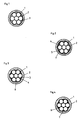
- 1 denotes the individual tensioning elements of the tensioning bundle.
- the individual tensioning elements 1 are constructed from strands. Envelopes of the clamping elements 1 or groups thereof are also possible, in particular made of plastic or by means of galvanic coating, in order to ensure corrosion protection for every individual element or group of elements.
- All clamping elements 1 are surrounded by a common plastic jacket 2. This is preferably made of polyethylene or a similar material.
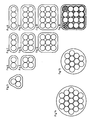
- the configuration of the tensioning elements 1 is selected such that a ring of six outer tensioning elements is arranged around a central tensioning element. In this case, the centers of three adjacent clamping elements 1 form an equilateral triangle.
- two rows of three (FIG. 10), two rows of four (FIG. 11) or two rows of any number of adjacent clamping elements can also be arranged one above the other.
- arrangements of three (FIG. 12, FIG. 13) or a plurality of rows of clamping elements lying one above the other are also possible.
- several concentric rings of clamping elements are also possible.
- two wreaths as shown in Fig. 14.
- a triangular arrangement as in FIG.
- FIG. 15 can also be supplemented by a further outer ring of clamping elements, so that, for example, the arrangement shown in FIG. 15 results (in FIGS. 5 to 15 only the schematic arrangement of the clamping elements 1 is shown Shown in the tension bundle without going into the structure according to the invention.
- the features according to the invention are the sliding mass penetrating between the casing 2 and the tensioning element 1 or the additional features provided negotiate all these statements). Another variant is shown in FIG. 16.
- the geometry of the tension bundle remains, i.e. the relative position of the centers of gravity of the clamping element arrangement and the sheathing, or the like, even in the case of deflections. receive.
- the clamping elements 1 touch each other as shown in Fig. 1, i.e. the tensioning elements 1 are arranged as closely as possible in the tension bundle.
- the gaps between the clamping elements are filled by the permanently plastic mass mentioned at the beginning.
- the inner wall 3 of the plastic jacket 2 is essentially circular in cross-section. It lies tightly against the outer tensioning elements 1. However, this tight contact of the jacket 2 with the tensioning elements 1 occurs only to such an extent that the relative mobility of the tensioning elements 1 relative to the plastic jacket 2, for example in the case of tensioning the tensioning elements, is maintained.
- the force with which the inner wall 3 of the casing 2 is pressed against the tensioning elements 1 must not exceed the value at which the coefficient of friction or adhesion between the two components 1, 2 becomes so great that no more displacement is possible.
- a permanently plastic mass can of course also be provided, this mass forming at least one film which has penetrated between the outermost elements 1 and the jacket 2 and has a thickness of at least one or less »m.
- each of the two outermost clamping elements 1 there is an intermediate space 5 which, in the case of an essentially circular outer cross section of the clamping elements, has a gusset outline.
- These gusset-shaped spaces 5 and the inner spaces 4 between the individual tensioning elements 1 can be filled with the previously mentioned permanently plastic mass.
- the plastic jacket 2 only fits tightly on some of the outermost tensioning elements 1.
- only one arrangement of tensioning elements is mentioned here, in which a plurality of concentric rings are arranged around a central element, and in which an essentially hexagonal arrangement ultimately results. If the inner wall 3 of the plastic jacket 2 is in the shape of an ice sheet, it will only fit snugly against the six clamping elements 1 which are at the greatest distance from the central element. Even in the case of triangular configurations of the clamping elements 1, this applies analogously to the three outermost clamping elements 1 which form the corners of the triangle.
- tensioning elements 1 now being held by an enveloping element 7 in the closest possible arrangement in which they touch one another.
- This variant also offers advantages in the manufacture of the tensioning bundle, since the individual tensioning elements 1 already during the passage through the extruder for applying the plastic jacket 2 to the tensioning elements 1 or through the anti-corrosion compound, in order to fill the spaces 4 and 5 with said mass , are kept in the desired configuration.
- the tensioning elements 1 therefore do not have to be subsequently compressed by additional devices in order to obtain the desired tight arrangement or to press excess lubricant out of the tensioning bundle, but rather the tensioning elements 1 with the mass located thereon can be introduced directly into the extruder.
- FIG. 3 Another variant is shown in FIG. 3.
- the inner wall 3 of the plastic jacket 2 also adjoins the outermost clamping elements 1 at any point along the circumference.
- the plastic jacket 2 fills at least part of the mostly gusset-shaped gaps that are delimited by the outermost clamping elements by protrusions 6 at least partially.
- the tensioning elements 1 lie close to one another, the material of the plastic jacket 2 cannot penetrate between the outermost tensioning elements 1, so that all the interstices 4 within the outermost ring of tensioning elements 1 continue to be filled only by the sliding compound.
- an enveloping element 7 can also be provided in this variant, as shown in FIG. 4.
- the procedure can advantageously be such that the tensioning elements 1 are passed through an extruder in which the plastic jacket 2 is applied so as to touch one another.
- extruders to apply jackets is a common technique.
- the next step in the process is to guide the tension bundle with the still heated plastic jacket into a vacuum calibrator.
- the jacket 2 is sucked onto the wall of the calibrator by creating a vacuum, so that during the subsequent cooling and shrinking of the plastic jacket, the clamping elements leave enough space for the elements 1 to slide in the jacket 2.
- the clamping elements can, if desired, be surrounded dry or by means of any application method with a thin layer of a permanently plastic mass.
- a thin layer of a permanently plastic mass could be provided by spraying on each individual clamping element or the final configuration of the clamping elements.
- the mass penetrates between the outermost clamping elements 1 and the inner wall 3 of the casing 2, so that the clamping elements 1 are slidable in the casing 2 and are surrounded on the outside by at least one film of the sliding compound.
- the tensioning elements 1 In order to keep the tensioning elements 1 in a configuration, especially during the manufacture of the tensioning bundle according to the invention, in which the individual elements 1 touch each other, it can advantageously be provided that the tensioning elements 1 already during the passage through the extruder in the first manufacturing process or in second case are held together by the permanently plastic mass by at least one enveloping element 7.
- a film or a mesh made of plastic or steel mesh can be used, which, however, is also attached during the passage of the mass or the extruder or after the tensioning bundle has passed through the mass.
- the given as an example of such an element 7 network has the advantage that it prevents the penetration of the sliding mass in the Spaces between the tensioning elements are not hindered, and even have a certain restraining effect for the portion of the mass which fills the outer spaces 5.
- the enveloping element 7 in its design as a net-like structure allows the projections 6 of the plastic jacket 2 to penetrate through the element 7 and thereby establish a firm connection between the enveloping element 7 and the jacket 2, while the tensioning elements 1 remain slidable.
- the element 7 also takes on the function of a stabilizing “reinforcement” of the plastic jacket 2.
- the complete and factory-made, if necessary already cut to length, bundle can be drawn in, whereupon the tensioning elements are tensioned together to the desired value using a tensioning press.
- the parallel bundle has the additional advantage that the tensioning elements can also be tensioned in groups or individually, because due to the construction according to the invention the tensioning elements 1 are easily movable relative to one another and relative to the plastic jacket 2.
- the anchoring in anchor bodies is preferably carried out using wedges for each clamping element separately. It is possible to anchor several tension bundles in a common anchor body or in individual anchor bodies.
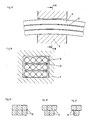
- FIGS. 19 to 21 show in which square tension bundles, such as those shown in FIGS. 9, 12 and 16, are selected, the individual bundle being designated by 10.
- 10 hard intermediate layers, e.g. B. made of sheet metal or the like.
- 11 denotes a deflection saddle on which three band-shaped clamping bundles 10, each consisting of four clamping elements, rest, between which one hard intermediate layer 12 is arranged.
- the tension bundles are preferably combined into a group of bundles touching one another.
- the pretensioning of the tensioning bundle should also be changed after the first installation and the first clamping, it can be provided as an alternative to the first-mentioned possibility that the tensioning bundle before or after tensioning with a permanently plastic mass, preferably grease, to squeeze.
- a permanently plastic mass preferably grease
Abstract
Description
Die Erfindung betrifft ein Spannbündel für vorgespannte Tragwerke, insbesondere aus Beton nach dem Oberbegriff des Patentanspruches 1, sowie ein Verfahren zu dessen Herstellung und Einbau.The invention relates to a tension bundle for prestressed structures, in particular made of concrete according to the preamble of
Die US-A-3 646 748 offenbart ein Spannbündel für vorgespannte Tragwerke aus Beton, bestehend aus mehreren in einer geordneten Konfiguration schraubenförmig verlaufenden und einander gegenseitig berührenden Spannelementen, welche von einem gemeinsamen aufgeschrumpften Kunststoffmantel umhüllt sind, wobei die Spannelemente vom Kunststoffmantel eng umhüllt sind und die Innenwandung des Kunststoffmantels an den äußeren Spanngliedern eng anliegt. Hiebei kann das Spannbündel irgendeine Form aufweisen. Hiebei ist vorgesehen, daß eine dauerplastische Masse die Zwischenräume ausfüllt und auch zwischen die Spannelemente und den Kunststoffmantel eingedrungen ist. Hiebei ist nur ein einziges Spannbündel vorgesehen, welches aus mehreren Drähten besteht, die m einen zentralen Draht gewunden sind, was den Nachteil hat, daß nur eine beschränkte Spannkraft erzielt werden kann.US-A-3 646 748 discloses a tension bundle for prestressed structures made of concrete, consisting of several tension elements running in an ordered configuration and mutually touching, which are encased by a common shrunk-on plastic jacket, the tensioning elements being closely enveloped by the plastic jacket and the inner wall of the plastic jacket is tight against the outer tendons. The tension bundle can have any shape. It is provided that a permanently plastic mass fills the gaps and also penetrates between the clamping elements and the plastic jacket. Hiebei only a single clamping bundle is provided, which consists of several wires that are wound in a central wire, which has the disadvantage that only a limited clamping force can be achieved.
Ein ähnliches Spannbündel offenbart auch die US-PS 4 623 504.A similar tension bundle is also disclosed in US Pat. No. 4,623,504.
Beim Spannbündel gemäß der EP-A-0 393 013 sind mehrere Spannglieder parallel zueinander verlaufend gemeinsam von einem Kunststoffmantel umgeben. Durch die dabei vorgesehenen Umhüllungen der einzelnen Spannglieder selbst ist der Querschnitt der beschriebenen und dargestellten Spannbündel um einiges größer als er eigentlich sein müßte. Auch der umhüllende Kunststoffmantel ist dadurch weiter von den einzelnen Spanngliedern entfernt als es notwendig wäre. Das Herstellungsverfahren gemäß der EP-A-0 393 913 umfaßt das Durchführen der Spannglieder durch einen Extruder, wobei jedoch kein Aufschrumpfen des Kunststoffmantels erfolgt, um beim Endprodukt einen möglichst kleinen Querschnitt des Bündels zu erzielen und doch die Beweglichkeit der einzelnen Spannglieder im Bündel gegenüber dem Mantel zu gestatten.In the tension bundle according to EP-A-0 393 013, a plurality of tendons running parallel to one another are surrounded jointly by a plastic jacket. Due to the provided envelopes of the individual tendons themselves, the cross section of the described and illustrated tension bundles is somewhat larger than it should actually be. The enveloping plastic sheath is also further away from the individual tendons than would be necessary. The manufacturing process according to EP-A-0 393 913 comprises passing the tendons through an extruder, but there is no shrinking of the plastic jacket in order to achieve the smallest possible cross-section of the bundle in the end product and yet the mobility of the individual tendons in the bundle relative to that Allow coat.
Im Spannbündel gemäß der GB-A-1 394 382 sind die Zwischenräume zwischen den Spannelementen untereinander durch Fett ausgefüllt. Hiebei besteht das Spannbündel aus mehreren Drähten, die parallel zueinander liegend in einer Umhüllung angeordnet sind. Drähte haben den Nachteil, daß sie verhältnismäßig steif sind und eine Haspel mit großem Durchmesser zum Aufwickeln der Spannglieder benötigen.In the tension bundle according to GB-A-1 394 382, the spaces between the tensioning elements are filled with one another by grease. Here it exists Tension bundles of several wires, which are arranged parallel to each other in a sheath. Wires have the disadvantage that they are relatively stiff and require a large diameter reel to wind up the tendons.
Weiters ist bekannt, Spannelemente ungeordnet in ein vorgefertigtes Hüllrohr einzuziehen und den verbleibenden Freiraum mit einer Gleitmasse, beispielsweise Fett, auszupressen. Allerdings kann bei derartig hergestellten Spannbündeln nur eine 50 bis 60%ige Füllung des Querschnittes des Bündels erzielt werden, sodaß ein relativ hoher Platzbedarf in bezug auf die Belastbarkeit des Spannbündels gegeben ist.Furthermore, it is known to pull tensioning elements into a prefabricated cladding tube in a disordered manner and to press out the remaining free space with a lubricant, for example grease. However, only 50 to 60% filling of the cross section of the bundle can be achieved with tension bundles produced in this way, so that there is a relatively high space requirement with regard to the load capacity of the tension bundle.
Überdies fällt der Schwerpunkt der Spannelement-Anordnung nicht mit dem Schwerpunkt der Umhüllung bzw. deren geometrischer Achse, zusammen. Zusätzlich ändert sich an jeder Umlenkstelle, d.h. bei Wechsel des Krümmungssinnes, die gegenseitige Lage der Schwerpunkte.In addition, the center of gravity of the clamping element arrangement does not coincide with the center of gravity of the casing or its geometric axis. In addition, changes occur at each deflection point, i.e. when the sense of curvature changes, the mutual position of the focal points.
Für Kabel, bei welchen die einzelnen Spannelemente nicht parallel zueinander, sondern im Bündel verdreht vorliegen, wurde vorgeschlagen, ("Structural Engineering International", Volum 1, Number 1, February 1991, pp.61,62), die inneren Zwischenräume zwischen den Drähten mit einer Korrosionsschutzmasse auszufüllen. Hiebei ist der innere Mantel auf die Drähte aufgebaut. Beim Spannen dieses Kabels dehnt sich der äußere Mantel mit dem Kabel in gleichem Maß. Dabei wird das Problem, die Reibungskräfte zwischen der Anordnung der Spannelemente und dem Mantel zu vermindern, nicht angesprochen.For cables in which the individual tensioning elements are not parallel to one another but twisted in the bundle, it has been proposed ("Structural Engineering International",
Beim Vorspannglied gemäß der AT-PS 269 439 sind im wesentlichen geradlinig verlaufend angeordnete und zueinander parallel ausgerichtete Teilelemente vorgesehen, die jedoch kraftschlüssig und schubfest miteinander verbunden sind. Diese Bindemittel, beispielsweise ein Metallkleber, füllt die Zwischenräume zwischen den Teilelementen aus, jedoch ist kein die Teilelemente gemeinsam umhüllender Kunststoffmantel vorgesehen. Das Problem der Abstandwahl zwischen den einzelnen Teilelementen wird nicht angesprochen und auch das Problem der Reibungskräfte zwischen den Spannelementen und einem Mantel bleibt ungelöst.In the prestressing member according to AT-PS 269 439, essentially linearly arranged and mutually parallel sub-elements are provided, which, however, are non-positively and shear-proof connected to each other. These binders, for example a Metal adhesive, fills the spaces between the sub-elements, but there is no plastic sheath that co-surrounds the sub-elements. The problem of the choice of distance between the individual sub-elements is not addressed, and the problem of the frictional forces between the clamping elements and a jacket remains unsolved.
Bei der Konstruktion gemäß der EP-A-0 160 135 ist die Beweglichkeit der Spannglieder des Bündels gegenüber dem sie umhüllenden Kunststoffmantel nicht gegeben. Vielmehr muß zu diesem Zweck außerhalb des Kunststoffmantels eine Gleitschicht und radial darauffolgend nochmals eine Umhüllung vorgesehen sein, wobei sich die Spannglieder zusammen mit dem sie umgebenden Mantel innerhalb der äußeren Umhüllung bewegen können. Darüberhinaus sind die äußeren Spannglieder des beschriebenen Spannbündels verdrillt um ein zentrales Spannglied angeordnet, sodaß sich bei Veränderung der Vorspannung in nachteiliger Weise Formänderungen, insbesondere Änderungen des Querschnittes des Spannbündels ergeben.In the construction according to EP-A-0 160 135, the tendons of the bundle cannot move relative to the plastic sheath enveloping them. Rather, for this purpose, a sliding layer must be provided outside of the plastic jacket and, radially thereafter, a jacket again, the tendons, together with the jacket surrounding them, being able to move within the outer jacket. In addition, the outer tendons of the tension bundle described are arranged twisted around a central tendon, so that there are disadvantageous changes in shape, in particular changes in the cross section of the tension bundle, when the pretension changes.
Ein Spannglied mit verdrillten Teilelementen ist auch in der WO-A-85/05394 beschrieben, die kein reines Spannbündel, sondern ein Bewehrungselement für Spannbetonkonstruktionen beschreibt. Dieses Bewehrungselement besteht aus einer Kombination von einem oder mehreren Spanngliedern herkömmlichen Bewehrungsstäben und zumindest einem dazwischen vorgesehenen Wendelstab als Abstandhalter. Bei dieser Konstruktion kommt es ebenfalls bei wechselnder Vorspannung zu den oben angesprochenenen nachteiligen Querschnittveränderungen des Bewehrungselementes und es wird weder auf eine Minimierung des Platzbedarfes noch auf die Verminderung der Reibungskräfte zwischen den Spannelementen und einem sie umhüllenden Mantel eingegangen.A tendon with twisted sub-elements is also described in WO-A-85/05394, which is not a pure tension bundle, but a Reinforcing element for prestressed concrete structures. This reinforcement element consists of a combination of one or more tendons of conventional reinforcement bars and at least one spiral bar provided between them as a spacer. With this design, the above-mentioned disadvantageous cross-sectional changes of the reinforcement element also occur with changing prestressing, and neither a minimization of the space requirement nor a reduction in the frictional forces between the tensioning elements and a jacket enveloping them is discussed.
Letzteres gilt auch für die EP-A-0 105 839, in der lediglich beschrieben ist, daß es bekannt ist, Spannelemente mit einer zweischichtigen Kunststoffumhüllung zu versehen. Dieses Dokument geht dann auf die Materialwahl für die Kunststoffumhüllung näher ein, beschäftigt sich jedoch nicht mit der Minimierung des Platzbedarfes der Herabsetzung der Reibung zwischen Spannelementen und Mantel, sowie der Beibeihaltung der Form und Geometrie des Spannbündels.The latter also applies to EP-A-0 105 839, in which it is only described that it is known to provide clamping elements with a two-layer plastic covering. This document then goes into more detail on the choice of material for the plastic sheathing, but does not deal with minimizing the space required to reduce the friction between the tensioning elements and the jacket, and maintaining the shape and geometry of the tensioning bundle.
Die EP-A-0 095 413 greift lediglich das Teilproblem der Gleitfähigkeit der Spannglieder gegenüber einem Hüllrohr auf, das auch aus Kunststoff angefertigt sein kann. Das letztgenannte Dokument gibt jedoch keinen Hinweis darauf, wie das Problem der Herabsetzung der Reibung gleichzeitig mit der weitgehenden Minimierung des Platzbedarfes und der Beibehaltung der Form und Geometrie eines Spannbündels aus mehreren einzelnen Spanngliedern gelöst werden kann.EP-A-0 095 413 only addresses the sub-problem of the sliding ability of the tendons with respect to a cladding tube, which can also be made of plastic. However, the latter document gives no indication of how the problem of reducing the friction can be solved at the same time as minimizing the space requirement and maintaining the shape and geometry of a tendon consisting of several individual tendons.
Die Aufgabe der vorliegenden Erfindung besteht darin, ein Spannbündel anzugeben, welches die oben angeführten Nachteile bei weitestgehende Minimierung des Platzbedarfes, gleichzeitiger Herabsetzung der Reibung und Beibehaltung der Form und Geometrie des Bündels in jeder Lage vermeidet und wobei Spannelemente auch einzeln oder in Gruppen spannbar sind und auf einer Haspel mit verhältnismäßig kleinem Durchmesser aufgedreht werden können.The object of the present invention is to provide a tensioning bundle which avoids the above-mentioned disadvantages while minimizing the space requirement as much as possible, at the same time reducing the friction and maintaining the shape and geometry of the bundle in any position, and wherein tensioning elements can also be tensioned individually or in groups and can be turned on a reel with a relatively small diameter.
Zur Lösung dieser Aufgabe dient die Maßnahme nach dem kennzeichnenden Teil des Patentanspruches 1.The measure according to the characterizing part of
Durch die dauerplastische Masse zwischen den Spannelementen selbst und insbesondere zwischen Spannelementen und Kunststoffmantel wird die Reibung weitgehend vermindert, das Spannen, auch einzelner und insbesondere der äußersten Spannelemente erleichter, wobei alle Vorteile des kompakten Parallel-Bündels beibehalten werden. Das Merkmal nach Anspruch 2 kann gleichzeitig auch dem Korrosionsschutz der Spannelemente dienen. Hiebei reicht eine Dicke von einem oder wenigen »m an den Berührungsstellen zwischen den Spannelementen bzw. diesen und dem Kunststoffmantel für das angestrebte reibungslose Spannen der Elemente aus.Due to the permanently plastic mass between the clamping elements themselves and in particular between the clamping elements and the plastic jacket, the friction is largely reduced, the clamping, also individual and especially the outermost clamping elements, is made easier, all advantages of the compact parallel bundle being retained. The feature of
Vorzugsweise werden als dauerplastische Masse Gleitmassen, z.B. umwelt-, insbesondere wasserverträgliche Fette, vorzugsweise auf Silikon- oder Mineralölbasis, oder Naturprodukte, z.B. auf Rapsbasis, verwendet.Sliding masses, e.g. environmentally friendly, especially water-compatible fats, preferably based on silicone or mineral oil, or natural products, e.g. rape-based.
Vorteilhafterweise sind die Spannelemente gemäß Anspruch 3 zusammengehalten, wodurch die geometrische Konfiguration des Bündels noch stabiler erhalten bleibt. Auch kann dadurch ein Schlagen der Spannelemente gegeneinander bzw. gegen die Innenwandung des Kunststoffmantels vermieden werden, sodaß die Gefahr von Beschädigungen noch weiter reduziert ist.The tensioning elements are advantageously held together, as a result of which the geometric configuration of the bundle is even more stable preserved. This also prevents the clamping elements from striking against one another or against the inner wall of the plastic jacket, so that the risk of damage is further reduced.
Eine vorteilhafte Variante bietet Anspruch 4.Claim 4 offers an advantageous variant.
Um eine weitestgehend freie Beweglichkeit der Spannelemente im Mantel zu gewährleisten, dient Anspruch 5. Durch dieses zusätzliche Merkmal wird einerseits eine bessere und exaktere Führung der äußersten Spannelemente auch zwischen allenfalls vorgesehenen umhüllenden Elementen sowie eine Reduzierung der notwendigen Menge an dauerplastischer Masse erzielt.In order to ensure that the tensioning elements in the casing can move as freely as possible,
Selbstverständlich können die Spannelemente einzeln oder in Gruppen korrosionsgeschützt sein, beispielseise durch eine Kunststoffumhüllung oder eine galvanische Beschichtung.Of course, the clamping elements can be protected against corrosion individually or in groups, for example by means of a plastic covering or a galvanic coating.
Vorteilhafterweise wird das beschriebene Spannbündel in einem Verfahren hergestellt, welches nach dem Oberbegriff des Anspruches 6 ausgeführt wird. Ein derartiges Verfahren ist im wesentlichen durch die FR-A-2 610 656 bekannt geworden. Aufgabe der Erfindung ist es, Maßnahmen zu treffen, daß beim anschließenden Kühlen und Schrumpfen des Kunststoffmantels dieser den Spannelementen ausreichend Platz läßt, damit die Elemente im Mantel gleiten können. Diese Maßnahmen werden durch den kennzeichnenden Teil des Patentanspruches 6 erfüllt.The clamping bundle described is advantageously produced in a method which is carried out according to the preamble of
Gemäß diesem Herstellungsverfahren wird das Spannbündel in der Konfiguration hergestellt, welche den geringstmöglichen Platzbedarf aufweist und durch das Ansaugen des Kunststoffmantels an die Innenwandung des Kalibrators wird erreicht, daß der Mantel so weit aufgeweitet wird, daß er beim anschließenden Abkühlen und damit verbundenen Schrumpfen nur in einem Maße enger wird, daß die innenliegenden Spannelemente noch genügend Freiheit haben, um gegenüber dem Kunststoffmantel gleiten zu können. Der Mantel muß also so weit aufgeweitet werden, daß seine Innenwandung beim fertigen Spannbündel nicht derart fest anliegt, um ein Gleiten der Spannelemente zu verhindern. Das genaue Ausmaß der notwendigen Aufweitung ist abhängig von verwendeten Material des Kunststoffmantels, da verschiedene Kunststoffe unterschiedliche Schrumpfungskoeffizienten aufweisen können. Auch der weiter oben angesprochene Reibungs- bw. Haftkoeffizient des Kunststoffmaterials gegenüber dem Material der Spannelemente beeinflußt die notwendige Aufweitung des Kunststoffmantels. Materialien mit sehr niedrigem Reibungs- bzw. Haftkoeffizienten können fester gegen die Spannelemente gepreßt werden als solche mit hohem Koeffizienten. Während im ersteren Fall geringe Aufweitungen möglich sind, muß im zweiten Fall der Kunststoffmantel so weit nach außen gesaugt werden, daß die Spannelemente nach dem anschließenden Aufschrumpfen des Mantels relativ locker umschlossen sind.According to this manufacturing process, the tension bundle is produced in the configuration which has the smallest possible space requirement and by sucking the plastic jacket onto the inner wall of the calibrator it is achieved that the jacket is expanded to such an extent that it only cools in one in the subsequent cooling and associated shrinkage Dimensions become narrower that the internal clamping elements still have enough freedom to slide against the plastic jacket. The jacket must therefore be widened to such an extent that its inner wall does not lie so tightly in the finished clamping bundle in order to prevent the clamping elements from sliding. The exact extent of the expansion required depends on the material of the plastic jacket used, since different plastics can have different shrinkage coefficients. The above mentioned friction or Adhesion coefficient of the plastic material compared to the material of the tensioning elements influences the necessary expansion of the plastic jacket. Materials with a very low coefficient of friction or adhesion can be pressed more firmly against the clamping elements than those with a high coefficient. While slight widening is possible in the former case, in the second case the plastic jacket must be sucked out so far that the tensioning elements are relatively loosely enclosed after the subsequent shrinking of the jacket.
Je nach dem Anwendungsgebiet für das fertige Spannbündel bzw. der gewünschten Vorgangsweie in bezug auf eine anschließende Auspressung des Raumes zwischen den Spannelementen mit unterschiedlichen Substanzen, kann vorgesehen sein, daß die Spannelemente trocken oder mit einer dünnen Schicht einer dauerplastischen Masse umgeben durch den Extruder geführt werden.Depending on the area of application for the finished clamping bundle or the desired procedure in relation to a subsequent squeezing of the space between the clamping elements with different substances, it can be provided that the clamping elements are passed through the extruder dry or with a thin layer of a permanently plastic mass .
Wenn das erfindungsgemäße Spannbündel derart ausgeführt sein soll, daß die Zwischenräume zwischen den Spannelementen durch eine dauerplastische Masse ausgefüllt sein sollen und diese Masse auch die Spannelemente umgeben soll, kann gemäß den Ansprüchen 6 und 7 das Herstellungsverfahren gekennzeichnet sein.If the tensioning bundle according to the invention is to be designed in such a way that the spaces between the tensioning elements are to be filled with a permanently plastic mass and this mass is also intended to surround the tensioning elements, according to
Die Maßnahme nach Anspruch 8 dient dazu, um das Führen der Spannelemente zu erleichtern und auch beim fertiggestellten Spannbündel die Konfiguration mit dem geringsten Platzbedarf beinhalten zu können.The measure according to claim 8 serves to facilitate the guiding of the tensioning elements and to be able to include the configuration with the smallest space requirement even when the tensioning bundle is finished.
Das erfindungsgemäße Spannbündel wird vorzugsweise nach Anspruch 9 eingebaut. Danach können die Spannelemente nach Anspruch 10 oder 11 verankert werden.The tension bundle according to the invention is preferably installed according to claim 9. Then the clamping elements can be anchored according to claim 10 or 11.
Als einer der letzten Verfahrensschritte beim Einbau des erfindungsgemäßen Spannbündels kann die Maßnahme nach Anspruch 12 vorgesehen sein.The measure according to
Bei Verwendung einer dauerplastischen Masse ist es wie angegeben möglich, sowohl vor als auch nach dem Spannen das Spannbündel zu verpressen, weshalb diese Möglichkeit hauptsächlich dort angewendet wird, wo die Spannelemente auch nach dem ersten Einbau nachgespannt werden müssen, bzw. deren Vorspannung allenfalls vermindert werden soll. Die zweite angegebene Möglichkeit des Verpressens mit einer aushärtenden Masse wird in jenen Fällen Anwendung finden, in welchen das Spannbündel über die gesamte Standzeit keiner Änderung der Vorspannungskräfte unterworfen wird.When using a permanently plastic mass, it is possible, as stated, to compress the tension bundle both before and after tensioning, which is why this option is mainly used where the tensioning elements have to be re-tensioned after the first installation, or their pretensioning is reduced if necessary should. The second specified possibility of pressing with a hardening mass will be used in those cases in which the tension bundle is not subjected to any change in the prestressing forces over the entire service life.
Das erfindungsgemäße Spannbündel findet in vorteilhafter Weise nach den Ansprüchen 13 und 14 Anwendung.The tension bundle according to the invention is advantageously used according to claims 13 and 14.
In der nachfolgenden Beschreibung sollen unter Bezugnahme auf die beigefügten Zeichnungen zwei Ausführungsbeispiele des erfindungsgemäßen Spannbündels näher beschrieben werden.In the following description, two exemplary embodiments of the tension bundle according to the invention will be described in more detail with reference to the accompanying drawings.
Dabei zeigen
- Fig. 1 das erfindungsgemäße Spannbündel mit im wesentlichen kreisförmigen inneren Querschnitt des Kunststoffmantels,
- Fig. 2 das gleiche Spannbündel der Fig. 1, jedoch mit einem umhüllenden Element,
- Fig. 3 eine Variante, bei welcher der Kunststoffmantel in die äußeren Zwischenräume der Litzen eindringt,
- Fig. 4 ein Spannbündel mit einem umhüllenden Element der Litzen, in einer Ausführung entsprechend der Fig. 3,
- Fig. 5 bis 16 verschiedene Varianten des erfindungsgemäßen Spannbündels mit unterschiedlichen Anzahlen und Anordnungen der einzelnen Litzen,
- Fig. 17 eine Umlenkstelle im Tragwerk mit drei Spannbündeln,
- Fig. 18 einen Schnitt nach der Linie XVIII-XVIII der Fig. 17 und
- Fig. 19 bis 21 drei Varianten der Anordnung von Spannbündeln, z. B. nach den Fig. 9, 12 und 16.
- 1 is the tension bundle according to the invention with a substantially circular inner cross section of the plastic jacket,
- 2 the same tension bundle of FIG. 1, but with an enveloping element,
- 3 shows a variant in which the plastic sheath penetrates into the outer spaces between the strands,
- 4 shows a tension bundle with an enveloping element of the strands, in an embodiment corresponding to FIG. 3,
- 5 to 16 different variants of the tension bundle according to the invention with different numbers and arrangements of the individual strands,
- 17 a deflection point in the structure with three tension bundles,
- Fig. 18 is a section along the line XVIII-XVIII of Fig. 17 and
- 19 to 21 three variants of the arrangement of clamping bundles, for. 9, 12 and 16.
In den Zeichnungen sind mit 1 die einzelnen Spannelementen des Spannbündels bezeichnet. Hiebei sind die einzelnen Spannelemente 1 aus Litzen aufgebaut. Auch Umhüllungen der Spannelemente 1 oder Gruppen davon sind möglich, insbesondere aus Kunststoff oder durch galvanische Beschichtung, um den Korrosionsschutz schon für jedes einzelne Element, bzw. jede Gruppe von Elementen sicherzustellen.In the drawings, 1 denotes the individual tensioning elements of the tensioning bundle. The
Alle Spannelemente 1 sind von einem gemeinsamen Kunststoffmantel 2 umgeben. Dieser ist vorzugsweise aus Polyäthylen oder einem ähnlichen Material hergestellt. Bei den dargestellten Ausführungsbeispielen ist die Konfiguration der Spannelemente 1 derart gewählt, daß ein Kranz von sechs äußeren Spannelementen um ein zentrales Spannelement herum angeordnet ist. Die Mittelpunkte je dreier benachbarter Spannelemente 1 bilden in diesem Fall ein gleichseitiges Dreieck.All clamping
Für bestimmte Anwendungsgebiete kann es jedoch auch notwendig sein, von dieser Anordnung abweichende Konfigurationen vorzusehen, bei welchen die Mittelpunkte aller Spannelemente 1 auf einer geraden Linie oder je vier Spannelemente in den Ecken eines Quadrates oder eines Rechteckes liegen. So könnten beispielsweise nur drei benachbarte Spannelemente 1 derart angeordnet sein, daß deren Mittelpunkte beispielsweise ein gleichseitiges Dreieck bilden (Fig. 5). Die einfachste Anordnung ergibt sich bei zwei nebeneinander liegenden Spannelementen. Das Spannbündel bildet in diesem Fall ein flaches Band (Fig. 6). Es können aber auch drei (Fig. 7), vier (Fig. 8) oder mehrere Spannelemente nebeneinander liegend in einer Reihe angeordnet sein. Des weiteren sind auch zwei oder mehrere übereinander liegende Reihen von Spannelementen denkbar. Beispielsweise ist in Fig. 9 ein Spannbündel dargestellt, bei welchem vier Spannelemente ein Quadrat bilden.For certain areas of application, however, it may also be necessary to provide configurations that deviate from this arrangement, in which the centers of all the
In entsprechender Weise können aber auch zwei Dreierreihen (Fig. 10), zwei Viererreihen (Fig. 11) oder zwei Reihen einer beliebigen Anzahl von nebeneinander liegenden Spannelementen übereinanderliegend angeordnet sein. Natürlich sind auch Anordnungen von drei (Fig. 12, Fig. 13) oder auch mehreren übereinander liegenden Reihen von Spannelementen möglich. Nach oben hin besteht für die Anzahl der möglichen Spannelemente 1 im Prinzip keine Beschränkung, sodaß im wesentlich beliebig viele Spannelemente in allen möglichen geometrischen Konfigurationen zu einem erfindungsgemäßen Spannbündel vereinigt werden können. So sind etwa auch mehrere konzentrische Kränze von Spannelementen möglich. Beispielsweise zwei Kränze wie in Fig. 14 dargestellt ist. Aber auch eine dreieckige Anordnung, wie in Fig. 5, kann um einen weiteren äußeren Kranz von Spannelementen ergänzt werden, sodaß sich beispielsweise die in Fig. 15 dargestellte Anordnung ergibt (in den Fig. 5 bis 15 ist nur die schematische Anordnung der Spannelemente 1 im Spannbündel dargestellt, ohne auf den erfindungsgemäßen Aufbau näher einzugehen. Natürlich sind die erfindungsgemäßen Merkmale der zwischen Mantel 2 und Spannelement 1 eindringenen Gleitmasse bzw. der zusätzlich vorgesehenen Merkmale bei allen diesen Ausführungen verhanden). Eine weitere Variante ist in Fig. 16 dargestellt.In a corresponding manner, however, two rows of three (FIG. 10), two rows of four (FIG. 11) or two rows of any number of adjacent clamping elements can also be arranged one above the other. Of course, arrangements of three (FIG. 12, FIG. 13) or a plurality of rows of clamping elements lying one above the other are also possible. There is in principle no limit to the number of
In jedem Fall bleibt die Geometrie des Spannbündels, d.h. die relative Lage der Schwerpunkte der Spannelement-Aordnung und der Umhüllung, auch bei Umlenkungen od.dgl. erhalten.In any case, the geometry of the tension bundle remains, i.e. the relative position of the centers of gravity of the clamping element arrangement and the sheathing, or the like, even in the case of deflections. receive.
Die Spannelemente 1 berühren einander wie in Fig. 1 dargestellt, d.h. die Spannelemente 1 sind dichtestmöglich aneinander liegend im Spannbündel angeordnet. Die Zwischenräume zwischen den Spannelementen untereinander sind durch die eingangs erwähnte dauerplastische Masse ausgefüllt.The
Die Innenwandung 3 des Kunststoffmantels 2 ist im Querschnitt im wesentlichen von kreisförmigem Umriß. Sie liegt an den äußeren Spannelementen 1 dicht an. Dieses dichte Anliegen des Mantels 2 an die Spannelemente 1 erfolgt jedoch nur in einem solchen Ausmaß, daß die relative Beweglichkeit der Spannelemente 1 gegenüber dem Kunststoffmantel 2, beispielsweise im Falle des Spannens der Spannelemente, gewahrt bleibt. Die Kraft, mit welcher die Innenwandung 3 des Mantels 2 gegen die Spannelemente 1 gepreßt wird, darf nicht jenen Wert überschreiten, bei welchem der Reibungs- oder Haftkoeffizient zwischen den beiden Bauteilen 1, 2, so groß wird, daß keine Verschiebung mehr möglich ist. Zur Verringerung des besagten Koeffizienten kann natürlich auch eine dauerplastische Masse vorgesehen sein, wobei diese Masse zumindest einen zwischen den äußersten Elementen 1 und dem Mantel 2 eingedrungenen Film mit zumindest einer Dicke von einem oder weniger »m bildet. Zwischen jeweils zwei der äußersten Spannelemente 1 liegt ein Zwischenraum 5, der bei im wesentlichen kreisförmigen äußeren Querschnitt der Spannelemente einen zwickelförmigen Umriß aufweist. Diese zwickelförmigen Zwischenräume 5 und die innenliegenden Zwischenräume 4 zwischen den einzelnen Spannelementen 1 können mit der bereits erwähnten dauerplastischen Masse ausgefüllt sein.The
Bei anders gestalteten Spannbündeln bezüglich des äußeren Umrisses der einzelnen Spannelemente 1 bzw. deren Konfiguration im Spannbündel kann vorgesehen sein, daß der Kunststoffmantel 2 nur an einigen der äußersten Spannelemente 1 eng anliegt. Als Beispiels sei hier nur eine Anordnung von Spannelementen genannt, bei welcher mehrere konzentrische Kränze um ein zentrales Element angeordnet sind, und bei welcher sich schließlich eine im wesentlichen hexagonale Anordnung ergibt. Bei keisförmigem Umriß der Innenwandung 3 des Kunststoffmantels 2 wird diese nur an den sechs Spannelementen 1 eng anliegen, welche vom zentralen Element den größten Abstand aufweisen. Auch bei dreieckigen Konfigurationen der Spannelemente 1 gilt dies für die jeweiligen drei äußersten Spannelemente 1, welche die Ecken des Dreieckes bilden, sinngemäß.In the case of differently designed tensioning bundles with regard to the outer contour of the
Die Fig.2 zeigt eine Variante des oben beschriebenen erfindungsgemäßen Spannbündels, wobei die Spannelemente 1 nun durch ein umhüllendes Element 7 in der dichtestmöglichen Anordnung, in welcher sie einander berühren, gehalten ist. Diese Variante bietet auch bei der Herstellung des Spannbündels Vorteile, da die einzelnen Spannelemente 1 bereits während des Durchführens durch den Extruder zur Aufbringung des Kunststoffmantels 2 auf die Spannelemente 1 bzw. durch die Korrosionsschutzmasse, um allenfalls die Zwischenräume 4 und 5 mit der besagten Masse füllen, in der gewünschten Konfiguration gehalten werden. Die Spannelemente 1 müssen daher nicht anschließend durch zusätzliche Einrichtungen zusammengedrückt werden, um die gewünschte dichte Anordnung zu erhalten, oder überschüssige Gleitmasse aus dem Spannbündel herauszupressen, sondern die Spannelemente 1 mit der daran befindlichen Masse können direkt in den Extruder eingeführt werden.2 shows a variant of the tensioning bundle according to the invention described above, the
Eine andere Variante zeigt die Fig.3. Hierbei schließt die Innenwandung 3 des Kunststoffmantels 2 ebenfalls an jeder Stelle entlang des Umfanges an den äußersten Spannelementen 1 an. Allerdings füllt der Kunststoffmantel 2 zumindest einen Teil der von den äußersten Spannelementen außen begrenzten und meist zwickelförmigen Zwischenräume durch Vorsprünge 6 zumindest teilweise aus. Da die Spannelemente 1 jedoch dicht an dicht liegen, kann das Material des Kunststoffmantels 2 nicht zwischen die äußersten Spannelemente 1 eindringen, sodaß alle innerhalb des äußersten Kranzes von Spannelementen 1 liegenden Zwischenräume 4 weiterhin nur von der Gleitmasse ausgefüllt sind. Selbstverständlich kann auch bei dieser Variante ein umhüllendes Element 7 vorgesehen sein, wie das in Fig. 4 dargestellt ist.Another variant is shown in FIG. 3. Here, the
Zur Herstellung des oben beschriebenen Spannbündels bzw. der oben beschriebenen Ausführungsformen kann vorteilhafterweise so vorgegangen werden, daß die Spannelemente 1 einander gegenseitig berührend durch einen Extruder geführt werden, in welchen der Kunststoffmantel 2 aufgebracht wird. Die verwendung von Extrudern zur Aufbringung von Ummantelungen ist dabei eine übliche Technik. Um jedoch ein ausreichendes Maß an Freiheit für die Spannelemente 1 gegenüber der Innenwandung 3 des Kunststoffmantels zu erzielen bzw. zu erreichen, daß der Kunststoffmantel 2 mit seiner Innenwandung 3 nicht derart fest an den Spannelementen 1 anliegt, um die relative Verschiebung dieser Bauteile gegeneinander zu verhindern, ist als anschließender Verfahrensschritt vorgesehen, das Spannbündel mit dem noch erwärmten Kunststoffmantel in einen Vakuumkalibrator zu führen. In diesem Gerät wird durch Erzeugen eines Vakuums der Mantel 2 derart an die Wand des Kalibrators gesaugt, sodaß beim anschließenden Kühlen und Schrumpfen des Kunststoffmantels dieser den Spannelementen ausreichend Platz läßt, damit die Elemente 1 im Mantel 2 gleiten können.To produce the above-described tension bundle or the above-described embodiments, the procedure can advantageously be such that the
Bei Durchführung durch den Extruder können die Spannelemente je nach Wunsch trocken oder mittels beliebiger Aufbringungsverfahren mit einer dünnen Schicht einer dauerplastischen Masse umgeben sein. Beispielsweise könnte eine derartige Masse durch Aufsprühen auf jedes einzelne Spannelement bzw, die bereits endgültige Konfiguration der Spannelemente vorgesehen sein.When carried out by the extruder, the clamping elements can, if desired, be surrounded dry or by means of any application method with a thin layer of a permanently plastic mass. For example, such a mass could be provided by spraying on each individual clamping element or the final configuration of the clamping elements.
Gemäß einer Abwandlung des erfindungsgemäßen Herstellungsverfahrens kann aber auch in einer Weise vorgegangen werden, bei welcher die Spannelemente sich gegenseitig berührend durch die dauerplastische Masse geführt werden, wobei die Masse in die inneren und äußeren Zwischenräume der Spannelemente 1 eindringt. Danach werden die Spannelemente 1 zusammen mit der daran befindlichen Masse durch einen Extruder geführt, in welchem der Kunststoffmantel aufgebracht wird. Die zwickelförmigen Zwischenräume werden hiebei zuerst mit der dauerplastischen Masse ausgefüllt, und im Extruder kann dann wahlweise die Aufextrudierung des Kunststoffmantels 2 derart gesteuert werden, daß entweder die äußeren Zwischenräume lediglich von der Gleitmasse ausgefüllt verbleiben, oder daß das Material des Kunststoffmantels 2 auch zumindest teilweise Vorsprünge 6 bildet, welche die besagten äußeren Zwischenräume zumindest teilweise ausfüllt. Diese Möglichkeit besteht natürlich auch für das zuerst beschriebene Verfahren.According to a modification of the manufacturing method according to the invention, however, it is also possible to proceed in a manner in which the clamping elements are guided in contact with one another through the permanently plastic mass, the mass penetrating into the inner and outer intermediate spaces of the
Im zweiten Fall dringt die Masse zwischen die äußersten Spannelemente 1 und der Innenwandung 3 des Mantels 2 ein, sodaß die Spannelemente 1 gleitfähig im Mantel 2 liegen und außen von zumindest einem Film der Gleitmasse umhüllt sind.In the second case, the mass penetrates between the
Um nun die Spannelemente 1 vor allem während der Herstellung des erfindungsgemäßen Spannbündels in einer Konfiguration zu halten, bei der die einzelnen Elemente 1 einander gegenseitig berühren, kann vorteilhafterweise vorgesehen sein, daß die Spannelemente 1 schon beim Durchführen durch den Extruder beim ersten Herstellungsverfahren bzw. im zweiten Fall durch die dauerplastische Masse durch zumindest ein umhüllendes Element 7 zusammengehalten sind. Dazu kann beispielsweise eine Folie oder ein Netz aus Kunststoff- oder Stahlgeflecht verwendet werden, welches jedoch auch während des Durchlaufens der Masse bzw. des Extruders oder auch nach dem Durchführen des Spannbündels durch die Masse angebracht werden.In order to keep the
Das als Beispiel für ein derartiges Element 7 angegebene Netz weist dabei den Vorteil auf, daß es das Eindringen der Gleitmasse in die Zwischenräume zwischen den Spannelementen nicht behindert, und sogar noch eine gewisse rückhaltende Wirkung für jenen Anteil der Masse aufweist, welche die äußeren Zwischenräume 5 ausfüllt. Wie aus Fig.4 ersichtlich, gestattet es das umhüllende Element 7 in seiner Ausführung als netzartige Struktur, daß auch die Vorsprünge 6 des Kunststoffmantels 2 durch das Element 7 hindurchdringen und dabei eine feste Verbindung zwischen dem umhüllenden Element 7 und dem Mantel 2 herstellen, während die Spannelemente 1 weiter gleitfähig bleiben. Das Element 7 übernimmt bei dieser Ausführungsform auch die Funktion einer stabilisierenden "Bewehrung" des Kunststoffmantels 2.The given as an example of such an
Beim Einbau des Spannbündels kann das komplette und werksmäßig gefertigte, allenfalls bereits abgelängte, Bündel eingezogen werden, worauf die Spannelemente gemeinsam mittels einer Spannpresse auf den gewünschten Wert gespannt werden. Das Parallel-Bündel hat zusätzlich den Vorteil, daß die Spannelemente aber auch in Gruppen oder einzeln gespannt werden können, da aufgrund der erfindungsgemäßen Konstruktion die Spannelemente 1 relativ zueinander und gegenüber dem Kunststoffmantel 2 leicht beweglich sind. Die Verankerung in Ankerkörpern erfolgt vorzugsweise unter Verwendung von Keilen für jedes Spannelement separat. Hierbei ist es möglich, mehrere Spannbündel in einem gemeinsamen Ankerkörper oder in einzelnen Ankerkörpern zu verankern.When installing the tensioning bundle, the complete and factory-made, if necessary already cut to length, bundle can be drawn in, whereupon the tensioning elements are tensioned together to the desired value using a tensioning press. The parallel bundle has the additional advantage that the tensioning elements can also be tensioned in groups or individually, because due to the construction according to the invention the
Die Spannbündel können auch in verschiedenen Konfigurationen dicht zusammengefaßt werden, wie z. B. die Fig. 19 bis 21 zeigen, in welchen quadratische Spannbündel, wie sie beispielsweise die Fig. 9, 12 und 16 zeigen, gewählt sind, wobei das einzelne Bündel mit 10 bezeichnet ist.The tension bundles can also be summarized in different configurations, such as. B. FIGS. 19 to 21 show in which square tension bundles, such as those shown in FIGS. 9, 12 and 16, are selected, the individual bundle being designated by 10.
An den Umlenkstellen im Tragwerk können zwischen je zwei Bündeln 10 harte Zwischenlagen, z. B. aus Blech oder dgl., eingelegt werden. Bei der in den Fig. 17 und 18 dargestellten Umlenkstelle ist mit 11 ein Umlenksattel bezeichnet, auf dem drei aus je vier Spannelementen bestehende bandförmige Spannbündel 10 aufliegen, zwischen denen eine harte Zwischenlage 12 angeordnet ist. Zwischen den allfälligen Umlenkstellen sind die Spannbündel vorzugsweise zu einer Gruppe von einander berührenden Bündeln zusammengefaßt.At the deflection points in the structure, 10 hard intermediate layers, e.g. B. made of sheet metal or the like. In the deflection point shown in FIGS. 17 and 18, 11 denotes a deflection saddle on which three band-shaped clamping bundles 10, each consisting of four clamping elements, rest, between which one hard
Selbstverständlich können im Rahmen der Erfindung verschiedene konstruktive Abänderungen vorgenommen werden. So besteht die Möglichkeit, die Spannelemente trocken zu verwenden oder nur mit einem Hauch dauerplastischer Masse zu überziehen, so daß die Gleitfähigkeit der Spannelemente innerhalb des Kunststoffmantels gewährleistet ist. In üblicher Weise kann der Raum zwischen den Spannelementen bzw. zwischen den Spannelementen und der Innenwandung des Kunststoffmantels nach dem Spannen der Spannelemente mit einer aushärtenden Masse, vorzugsweise Zement, verpreßt werden. In diesem Fall wird eine weitere Änderung der Vorspannung durch die Aushärtung der Masse und das feste Einbetten der Spannelemente darin unterbunden. Wenn dagegen vorgesehen bzw. gewünscht ist, daß die Vorspannung des Spannbündels auch nach dem ersten Einbau und der ersten Aufspannung verändert werden soll, kann alternativ zur erstgenannten Möglichkeit vorgesehen sein, daß Spannbündel vor oder auch nach dem Spannen mit einer dauerplastischen Masse, vorzugsweise Fett, zu verpressen.Of course, various design changes can be made within the scope of the invention. So there is the possibility to use the tensioning elements dry or to cover them only with a hint of permanently plastic mass, so that the sliding properties of the tensioning elements within the plastic jacket is guaranteed. In the usual way, the space between the tensioning elements or between the tensioning elements and the inner wall of the plastic jacket can be pressed with a hardening mass, preferably cement, after the tensioning elements have been tensioned. In this case, a further change in the pretension is prevented by the hardening of the mass and the firm embedding of the tensioning elements in it. If, on the other hand, it is provided or desired that the pretensioning of the tensioning bundle should also be changed after the first installation and the first clamping, it can be provided as an alternative to the first-mentioned possibility that the tensioning bundle before or after tensioning with a permanently plastic mass, preferably grease, to squeeze.
Claims (14)
- Tensioning bundle for prestressed structures, in particular made of concrete, the tensioning bundles comprising a plurality of tensioning elements in an ordered configuration and in mutual contact, whose centre-points lie at the corners of equilateral triangles or of rectangles or on a straight line, and which are sheathed by at least one common, shrunk-on plastic sheath (2), preferably of polyethylene, the gaps (4, 5) between the tensioning elements being filled by a permanently flexible compound which has also penetrated between the tensioning elements and the plastic sheath (2), which plastic sheath (2) surrounds the tensioning elements, enclosing them tightly, characterized in that the tensioning elements comprise strands (1) extending parallel to one another.
- Tensioning bundle according to Claim 1, characterized in that the strands (1) are protected against corrosion individually or in groups by a surface coating, for example by a plastic sheathing or a galvanic coating.
- Tensioning bundle according to Claim 1, characterized in that the strands (1) are held together by at least one sheathing element (7), for example a film or a net of plastic or steel, within the plastic sheath (2).
- Tensioning bundle according to Claim 1, characterized in that the plastic sheath (2) at least partially fills at least some of the gaps (5), which are bounded on the outside by the outermost strands (1) and are usually gusset-shaped, by means of projections (6).
- Tensioning bundle according to Claim 1, characterized in that materials having the lowest possible friction coefficient compared to the material of the tensioning elements (1) are selected for the plastic sheath (2).
- Method for the manufacture of a tensioning bundle according to Claim 1, the strands (1) being passed in parallel through an extruder in which the plastic sheath (2) is applied, the tensioning bundle subsequently being guided with the still heated plastic sheath into a vacuum calibrator, the plastic sheath (2) being sucked onto the wall of the vacuum calibrator by generating a vacuum, such that, during the subsequent cooling and shrinking of the plastic sheath (2), the latter leaves the strands (1) sufficient room for them to be able to slide in the plastic sheath (2), characterized in that the strands (1) are surrounded by a thin layer of a permanently flexible compound prior to introduction into the extruder.
- Method according to Claim 6, characterized in that the strands (1) are guided in parallel and in mutual contact through the permanently flexible compound, the latter penetrating into the gaps (4, 5) and surrounding the strands (1), whereupon the latter are passed jointly and together with the permanently flexible compound through the extruder.
- Method according to one of Claims 6 or 7, characterized in that the strands (1) are surrounded by a sheathing element (7).
- Method for installing a tensioning bundle according to one of Claims 1 to 5, characterized in that the complete tensioning bundle is drawn into the structure or applied to the latter and the strands (1) are tensioned jointly, possibly in groups or individually.
- Method according to Claim 9, characterized in that the strands (1) are anchored individually using wedges in anchoring bodies.
- Method according to Claim 10, characterized in that a plurality of tensioning bundles are anchored in a common anchoring body.
- Method according to one of Claims 9 to 11, characterized in that the end of the tensioning bundles is compressed before or after tensioning with a permanently flexible compound, preferably with grease or after tensioning with a curing compound, preferably cement.
- Use of the tensioning bundles according to at least one of Claims 1 to 5 for inner or outer pretensioning arrangements in a structure made of concrete using a plurality of such tensioning bundles between which intermediate layers of hard material are inserted at any deflection points present, the ends of the tensioning bundles being anchored in a common anchoring body or in separate anchoring bodies.
- Use of tensioning bundles according to Claim 13, characterized in that a plurality of tensioning bundles are combined between the deflection points to form a group of mutually contacting bundles.
Applications Claiming Priority (2)
| Application Number | Priority Date | Filing Date | Title |
|---|---|---|---|
| AT0061491A AT400736B (en) | 1991-03-19 | 1991-03-19 | TENSION BUNDLE FOR PRELOADED CONCRETE STRUCTURES |
| AT614/91 | 1991-03-19 |
Publications (2)
| Publication Number | Publication Date |
|---|---|
| EP0505351A1 EP0505351A1 (en) | 1992-09-23 |
| EP0505351B1 true EP0505351B1 (en) | 1995-12-20 |
Family
ID=3495260
Family Applications (1)
| Application Number | Title | Priority Date | Filing Date |
|---|---|---|---|
| EP92890062A Expired - Lifetime EP0505351B1 (en) | 1991-03-19 | 1992-03-18 | Tensioning strand for prestressed concrete structures |
Country Status (3)
| Country | Link |
|---|---|
| EP (1) | EP0505351B1 (en) |
| AT (2) | AT400736B (en) |
| DE (1) | DE59204718D1 (en) |
Cited By (1)
| Publication number | Priority date | Publication date | Assignee | Title |
|---|---|---|---|---|
| US8973803B2 (en) | 2008-02-14 | 2015-03-10 | Ethicon Endo-Surgery, Inc. | Surgical stapling apparatus with control features operable with one hand |
Families Citing this family (8)
| Publication number | Priority date | Publication date | Assignee | Title |
|---|---|---|---|---|
| AT402745B (en) * | 1995-11-30 | 1997-08-25 | Thal Hermann Dipl Ing | BAND-SHAPED TENSIONING ELEMENT |
| DE19711002C2 (en) * | 1997-03-17 | 1999-12-30 | Suspa Spannbeton Gmbh | Prefabricated tension member, especially as a circumferential tendon for large concrete containers |
| AT407545B (en) * | 1997-08-04 | 2001-04-25 | Thal Hermann Dipl Ing | TENSION BUNDLE AND METHOD AND DEVICE FOR PRODUCING THE SAME |
| EP0913538A3 (en) * | 1997-10-29 | 2001-04-04 | Bilfinger + Berger Bauaktiengesellschaft | Device for the tensioning without bonding of building constructions |
| AU6972500A (en) * | 1999-09-07 | 2001-04-10 | Hermann Thal | Tensioning mechanism, anchoring wedge for anchoring said tensioning mechanism and method for producing said anchoring wedge |
| AT504604A1 (en) * | 2006-12-11 | 2008-06-15 | Thal Hermann | METHOD FOR REINFORCING CONCRETE STRUCTURES AND ARRANGEMENT OF RELATED LINES OF COATED REINFORCEMENT BARS IN THE CONCRETE BODY |
| AT504886B1 (en) * | 2007-09-10 | 2008-09-15 | Thal Hermann Dipl Ing | BANDED TENSIONING ELEMENT |
| CN104452373A (en) * | 2014-11-26 | 2015-03-25 | 胡国良 | Drag rope and method for manufacturing drag rope |
Citations (1)
| Publication number | Priority date | Publication date | Assignee | Title |
|---|---|---|---|---|
| US3646748A (en) * | 1970-03-24 | 1972-03-07 | Frederic A Lang | Tendons for prestressed concrete and process for making such tendons |
Family Cites Families (13)
| Publication number | Priority date | Publication date | Assignee | Title |
|---|---|---|---|---|
| AT19280B (en) * | 1901-02-18 | 1905-02-25 | Josef Henderson Campbell | |
| DE1525129C3 (en) * | 1965-01-02 | 1975-01-30 | Intercontinentale-Technik Gesellschaft Fuer Planung Und Konstruktion Mbh, 8000 Muenchen | Bundle of high-strength metallic longitudinal elements |
| GB1394362A (en) * | 1971-05-06 | 1975-05-14 | Johnson Firth Brown Ltd | Pre-stressing tendon |
| DE3234246C2 (en) * | 1982-09-15 | 1984-11-29 | Ulrich Dr.Ing. e.h. Dr.Ing. 8000 München Finsterwalder | Cables, in particular for cable-stayed bridges made of prestressed concrete |
| US4552815A (en) * | 1982-10-01 | 1985-11-12 | Ciba Geigy Corporation | Prestressing elements coated with plastic material and process for making them |
| US4445321A (en) * | 1982-11-29 | 1984-05-01 | Hutchinson Raymond E | Tendon construction for posttensioning prestressed concrete and the method of making such tendons |
| DE3418318A1 (en) * | 1984-05-17 | 1985-11-21 | Friedrich J. Ing. Rottenmann Bodner | REINFORCEMENT ELEMENT FOR CONCRETE CONSTRUCTION PARTS |
| US4623504A (en) * | 1984-10-22 | 1986-11-18 | Smith Larry F | Method and apparatus for making post-tensioning tendons for concrete |
| JPS61122361A (en) * | 1984-11-20 | 1986-06-10 | 川鉄テクノワイヤ株式会社 | Unbond pc steel twisted wire |
| FR2579236B1 (en) * | 1985-03-19 | 1987-07-17 | Elf France | PREFABRICATED PRE-STRESS CABLE AND MANUFACTURING METHOD THEREOF |
| FR2610656B1 (en) * | 1987-02-11 | 1991-06-21 | Citra | DEVICE FOR GUIDING THE PRE-STRESS CABLES OF A CIVIL WORK |
| DE3838069C2 (en) * | 1988-11-10 | 1995-12-14 | Hochtief Ag Hoch Tiefbauten | Transportable reinforcement unit that can be concreted in for prestressing reinforced concrete structures |
| ES2042271T5 (en) * | 1989-04-12 | 1997-11-01 | Vorspann Technik Gmbh | TENSIONING GROUP OF VARIOUS TENSIONING ELEMENTS SUCH AS LACES, RODS OR WIRES. |
-
1991
- 1991-03-19 AT AT0061491A patent/AT400736B/en not_active IP Right Cessation
-
1992
- 1992-03-18 EP EP92890062A patent/EP0505351B1/en not_active Expired - Lifetime
- 1992-03-18 AT AT92890062T patent/ATE131895T1/en active
- 1992-03-18 DE DE59204718T patent/DE59204718D1/en not_active Expired - Lifetime
Patent Citations (1)
| Publication number | Priority date | Publication date | Assignee | Title |
|---|---|---|---|---|
| US3646748A (en) * | 1970-03-24 | 1972-03-07 | Frederic A Lang | Tendons for prestressed concrete and process for making such tendons |
Cited By (1)
| Publication number | Priority date | Publication date | Assignee | Title |
|---|---|---|---|---|
| US8973803B2 (en) | 2008-02-14 | 2015-03-10 | Ethicon Endo-Surgery, Inc. | Surgical stapling apparatus with control features operable with one hand |
Also Published As
| Publication number | Publication date |
|---|---|
| AT400736B (en) | 1996-03-25 |
| ATA61491A (en) | 1995-07-15 |
| DE59204718D1 (en) | 1996-02-01 |
| ATE131895T1 (en) | 1996-01-15 |
| EP0505351A1 (en) | 1992-09-23 |
Similar Documents
| Publication | Publication Date | Title |
|---|---|---|
| EP0393013B2 (en) | Tensioning-bundle comprising tensioning members | |
| DE3318233C3 (en) | ||
| DE2829205C2 (en) | ||
| DE60102061T4 (en) | Individually protected strand, its use in construction engineering and process for its production | |
| DE2831433A1 (en) | LUBRICATED WIRE ROPE IMPREGNATED WITH PLASTIC | |
| DE60026330T2 (en) | CABLE OF PARALLEL THREADS FOR A CONSTRUCTION WORK, ANCHORAGE AND ANCHORING PROCESS FOR SUCH CABLE | |
| CH656970A5 (en) | HIGHLY FLEXIBLE INSULATED ELECTRIC CABLE, METHOD FOR THE PRODUCTION AND USE OF THE CABLE. | |
| EP0505351B1 (en) | Tensioning strand for prestressed concrete structures | |
| DE2430170C3 (en) | Tendon made of high tensile strength steel for prestressed concrete components or structures | |
| DE3838069C2 (en) | Transportable reinforcement unit that can be concreted in for prestressing reinforced concrete structures | |
| DE3831069C2 (en) | ||
| DE2518513A1 (en) | PRESSURE PIPE MADE OF PRECAST CONCRETE | |
| AT402745B (en) | BAND-SHAPED TENSIONING ELEMENT | |
| DE865048C (en) | Method for anchoring wires or wire bundles as tendons of structures made of concrete or other masses | |
| DE1559568B2 (en) | TENSIONER | |
| DE19731946A1 (en) | Fastening device for pipes and other objects and method for their production | |
| WO1985005394A1 (en) | Reinforcement element based on steel parts for prestressed concrete constructions and prefabricated prestressed concrete elements | |
| AT400735B (en) | Prestressing bundle | |
| AT407766B (en) | Prestressing cable | |
| DE3039080C2 (en) | Removable, multi-part tension member for a grouting anchor | |
| DE3045007A1 (en) | Wedge device for anchoring a prestressed reinforcement | |
| DE3234246A1 (en) | Cable, in particular for cable-stayed bridges of reinforced concrete | |
| AT409280B (en) | Prestressing cable - has specified plastic individual strand and overall insulation | |
| AT404956B (en) | Prestressing cable | |
| EP1210478B1 (en) | Tensioning mechanism, anchoring of said tensioning mechanism and method for producing said anchoring |
Legal Events
| Date | Code | Title | Description |
|---|---|---|---|
| PUAI | Public reference made under article 153(3) epc to a published international application that has entered the european phase |
Free format text: ORIGINAL CODE: 0009012 |
|
| AK | Designated contracting states |
Kind code of ref document: A1 Designated state(s): AT CH DE FR GB IT LI |
|
| 17P | Request for examination filed |
Effective date: 19930312 |
|
| 17Q | First examination report despatched |
Effective date: 19931020 |
|
| GRAA | (expected) grant |
Free format text: ORIGINAL CODE: 0009210 |
|
| AK | Designated contracting states |
Kind code of ref document: B1 Designated state(s): AT CH DE FR GB IT LI |
|
| REF | Corresponds to: |
Ref document number: 131895 Country of ref document: AT Date of ref document: 19960115 Kind code of ref document: T |
|
| REF | Corresponds to: |
Ref document number: 59204718 Country of ref document: DE Date of ref document: 19960201 |
|
| ITF | It: translation for a ep patent filed |
Owner name: STUDIO TORTA SOCIETA' SEMPLICE |
|
| GBT | Gb: translation of ep patent filed (gb section 77(6)(a)/1977) |
Effective date: 19960122 |
|
| ET | Fr: translation filed | ||
| REG | Reference to a national code |
Ref country code: CH Ref legal event code: NV Representative=s name: KELLER & PARTNER PATENTANWAELTE AG |
|
| PLBE | No opposition filed within time limit |
Free format text: ORIGINAL CODE: 0009261 |
|
| STAA | Information on the status of an ep patent application or granted ep patent |
Free format text: STATUS: NO OPPOSITION FILED WITHIN TIME LIMIT |
|
| 26N | No opposition filed | ||
| PGFP | Annual fee paid to national office [announced via postgrant information from national office to epo] |
Ref country code: GB Payment date: 19980312 Year of fee payment: 7 |
|
| PG25 | Lapsed in a contracting state [announced via postgrant information from national office to epo] |
Ref country code: GB Free format text: LAPSE BECAUSE OF NON-PAYMENT OF DUE FEES Effective date: 19990318 |
|
| GBPC | Gb: european patent ceased through non-payment of renewal fee |
Effective date: 19990318 |
|
| PGFP | Annual fee paid to national office [announced via postgrant information from national office to epo] |
Ref country code: IT Payment date: 20090330 Year of fee payment: 18 Ref country code: FR Payment date: 20090331 Year of fee payment: 18 |
|
| PGFP | Annual fee paid to national office [announced via postgrant information from national office to epo] |
Ref country code: CH Payment date: 20090427 Year of fee payment: 18 |
|
| REG | Reference to a national code |
Ref country code: CH Ref legal event code: PL |
|
| REG | Reference to a national code |
Ref country code: FR Ref legal event code: ST Effective date: 20101130 |
|
| PG25 | Lapsed in a contracting state [announced via postgrant information from national office to epo] |
Ref country code: FR Free format text: LAPSE BECAUSE OF NON-PAYMENT OF DUE FEES Effective date: 20100331 |
|
| PG25 | Lapsed in a contracting state [announced via postgrant information from national office to epo] |
Ref country code: LI Free format text: LAPSE BECAUSE OF NON-PAYMENT OF DUE FEES Effective date: 20100331 Ref country code: CH Free format text: LAPSE BECAUSE OF NON-PAYMENT OF DUE FEES Effective date: 20100331 |
|
| PG25 | Lapsed in a contracting state [announced via postgrant information from national office to epo] |
Ref country code: IT Free format text: LAPSE BECAUSE OF NON-PAYMENT OF DUE FEES Effective date: 20100318 |
|
| PGFP | Annual fee paid to national office [announced via postgrant information from national office to epo] |
Ref country code: AT Payment date: 20110315 Year of fee payment: 20 |
|
| PGFP | Annual fee paid to national office [announced via postgrant information from national office to epo] |
Ref country code: DE Payment date: 20110511 Year of fee payment: 20 |
|
| REG | Reference to a national code |
Ref country code: DE Ref legal event code: R071 Ref document number: 59204718 Country of ref document: DE |
|
| REG | Reference to a national code |
Ref country code: DE Ref legal event code: R071 Ref document number: 59204718 Country of ref document: DE |
|
| PG25 | Lapsed in a contracting state [announced via postgrant information from national office to epo] |
Ref country code: DE Free format text: LAPSE BECAUSE OF EXPIRATION OF PROTECTION Effective date: 20120320 |
|
| REG | Reference to a national code |
Ref country code: AT Ref legal event code: MK07 Ref document number: 131895 Country of ref document: AT Kind code of ref document: T Effective date: 20120318 |