EP0504594A2 - Device for the positive relief of a take-up spool in an ink ribbon cartridge - Google Patents
Device for the positive relief of a take-up spool in an ink ribbon cartridge Download PDFInfo
- Publication number
- EP0504594A2 EP0504594A2 EP92102568A EP92102568A EP0504594A2 EP 0504594 A2 EP0504594 A2 EP 0504594A2 EP 92102568 A EP92102568 A EP 92102568A EP 92102568 A EP92102568 A EP 92102568A EP 0504594 A2 EP0504594 A2 EP 0504594A2
- Authority
- EP
- European Patent Office
- Prior art keywords
- take
- spool
- reel
- tape
- ink ribbon
- Prior art date
- Legal status (The legal status is an assumption and is not a legal conclusion. Google has not performed a legal analysis and makes no representation as to the accuracy of the status listed.)
- Withdrawn
Links
Images
Classifications
-
- B—PERFORMING OPERATIONS; TRANSPORTING
- B41—PRINTING; LINING MACHINES; TYPEWRITERS; STAMPS
- B41J—TYPEWRITERS; SELECTIVE PRINTING MECHANISMS, i.e. MECHANISMS PRINTING OTHERWISE THAN FROM A FORME; CORRECTION OF TYPOGRAPHICAL ERRORS
- B41J33/00—Apparatus or arrangements for feeding ink ribbons or like character-size impression-transfer material
- B41J33/14—Ribbon-feed devices or mechanisms
- B41J33/52—Braking devices therefor
-
- B—PERFORMING OPERATIONS; TRANSPORTING
- B41—PRINTING; LINING MACHINES; TYPEWRITERS; STAMPS
- B41J—TYPEWRITERS; SELECTIVE PRINTING MECHANISMS, i.e. MECHANISMS PRINTING OTHERWISE THAN FROM A FORME; CORRECTION OF TYPOGRAPHICAL ERRORS
- B41J32/00—Ink-ribbon cartridges
Definitions
- the invention relates to an arrangement on a tape cassette for relieving the force on the take-up reel provided with a slip clutch, in which the ink or thermal ribbon is guided from a supply reel via deflection rollers past a printhead to the take-up reel.
- Ribbon and thermal print cartridges generally have a supply spool and a take-up spool for the ribbon.
- Several deflection rollers serve to guide the belt.
- Various possibilities are known for this (DE-38 08 603 A1, DE-38 00 113 A1, EP-0 189 984 B1) to hold the band under appropriate pretension and to prevent sagging.
- a belt drive for winding continuously exerts a force on the belt. This can lead to the fact that even if the paper to be printed is not in contact with the tape or is in contact with the tape but is not moved, an additional tape feed occurs due to high tensile forces through the take-up reel.
- the object of the invention was to ensure that the winding is decoupled from the forces that can be achieved by friction between the ribbon and the paper, both when the take-up train is switched on permanently and when required.
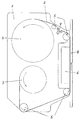
- the cassette 1 for ink or thermal ribbons 2 encloses a supply reel 3 and a take-up reel 4.
- a plurality of deflection rollers 5 serve to guide the tape.
- the tape 2 is guided from the supply reel 3 to the take-up reel 4 via the print head 6.
- a meandering tape guide 7 is additionally provided between the deflection rollers 5 arranged after the print head 6 and in front of the take-up reel 4.
- This meandering band guide 7 consists of several staggered rollers. An arrangement of three rollers has proven to be expedient.
- the meandering tape guide 7 relieves the load on the take-up spool 4, since an increased frictional force is achieved due to the wrap angle of the tape 2 on the tape guide 7. Thus, the tensile force can vary to a considerable extent without the tape 2 being pulled off the supply reel 3 in the idle state. Only when the wrap angle is reduced by the feed of the tape 2 through the friction between tape 2 and paper 8, a tape transport takes place.
Abstract
Description
Die Erfindung betrifft eine Anordnung an einer Bandkassette zur kraftmäßigen Entlastung der mit einer Rutschkupplung versehenen Aufwickelspule, bei der das Farb- oder Thermoband von einer Vorratsspule über Umlenkrollen an einem Druckkopf vorbei zur Aufwickelspule geführt wird.The invention relates to an arrangement on a tape cassette for relieving the force on the take-up reel provided with a slip clutch, in which the ink or thermal ribbon is guided from a supply reel via deflection rollers past a printhead to the take-up reel.
Farbband- und Thermodruckkassetten weisen allgemein eine Vorratsspule und eine Aufwickelspule für das Band auf. Mehrere Umlenkrollen dienen der Führung des Bandes. Zur Erzielung gleichbleibender Druckqualität ist es notwendig, das Band, insbesondere bei Thermodruckern, straff zu spannen. Hierzu sind verschiedene Möglichkeiten bekannt (DE-38 08 603 A1, DE-38 00 113 A1, EP-0 189 984 B1), das Band unter einer entsprechenden Vorspannung zu halten und einen Durchhang zu vermeiden. Gemeinsam ist diesen Anordnungen, daß auch im Ruhezustand bei eingeschalteten Maschinen ein Riementrieb zum Aufwickeln ständig auf das Band eine Kraft ausübt. Dies kann dazu führen, daß auch dann, wenn das zu bedruckende Papier nicht im Kontakt mit dem Band steht, oder im Kontakt mit dem Band steht aber nicht bewegt wird, ein zusätzlicher Bandvorschub aufgrund großer Zugkräfte durch die Aufwickelspule geschieht.Ribbon and thermal print cartridges generally have a supply spool and a take-up spool for the ribbon. Several deflection rollers serve to guide the belt. In order to achieve consistent print quality, it is necessary to tighten the ribbon, especially with thermal printers. Various possibilities are known for this (DE-38 08 603 A1, DE-38 00 113 A1, EP-0 189 984 B1) to hold the band under appropriate pretension and to prevent sagging. Common to these arrangements is that even when the machine is in the idle state, a belt drive for winding continuously exerts a force on the belt. This can lead to the fact that even if the paper to be printed is not in contact with the tape or is in contact with the tape but is not moved, an additional tape feed occurs due to high tensile forces through the take-up reel.
Der Erfindung lag die Aufgabe zugrunde, sowohl bei permanentem als auch bei bedarfsweise eingeschaltetem Aufwickelzug eine Entkopplung der Aufwicklung von den durch Reibung zwischen Farbband und Papier erzielbaren Kräften zu gewährleisten.The object of the invention was to ensure that the winding is decoupled from the forces that can be achieved by friction between the ribbon and the paper, both when the take-up train is switched on permanently and when required.
Diese Aufgabe ist durch die Erfindung gelöst, wie sie im ersten Patentanspruch dargelegt ist. Weitere vorteilhafte Ausbildungen sind Gegenstand der Unteransprüche.This object is achieved by the invention as set out in the first claim. Further advantageous developments are the subject of the dependent claims.
Anhand einer Zeichnung wird die Erfindung nachfolgend näher beschrieben.The invention is described in more detail below with reference to a drawing.
Die Kassette 1 für Farb- oder Thermobänder 2 umschließt eine Vorratsspule 3 und eine Aufwickelspule 4. Mehrere Umlenkrollen 5 dienen der Bandführung. Über den Druckkopf 6 wird das Band 2 von der Vorratsspule 3 zur Aufwickelspule 4 geführt. Zwischen den, nach dem Druckkopf 6 und vor der Aufwickelspule 4 angeordneten Umlenkrollen 5 ist eine mäanderförmige Bandführung 7 zusätzlich vorgesehen. Diese mäanderförmige Bandführung 7 besteht aus mehreren versetzt angeordneten Rollen. Als zweckmäßig hat sich eine Anordnung aus drei Rollen erwiesen. Durch die mäanderförmige Bandführung 7 wird eine kraftmäßige Entlastung der Aufwickelspule 4 erreicht, da bedingt durch den Umschlingungswinkel des Bandes 2 an der Bandführung 7 eine erhöhte Reibkraft erzielt wird. Somit kann die Zugkraft in erheblichem Umfang variieren, ohne daß im Ruhezustand das Band 2 von der Vorratsspule 3 abgezogen wird. Erst wenn der Umschlingungswinkel durch den Vorschub des Bandes 2 über die Reibung zwischen Band 2 und Papier 8 verringert wird, findet ein Bandtransport statt.The
Claims (3)
Applications Claiming Priority (2)
| Application Number | Priority Date | Filing Date | Title |
|---|---|---|---|
| DE9103568U DE9103568U1 (en) | 1991-03-21 | 1991-03-21 | |
| DE9103568U | 1991-03-21 |
Publications (2)
| Publication Number | Publication Date |
|---|---|
| EP0504594A2 true EP0504594A2 (en) | 1992-09-23 |
| EP0504594A3 EP0504594A3 (en) | 1993-01-13 |
Family
ID=6865584
Family Applications (1)
| Application Number | Title | Priority Date | Filing Date |
|---|---|---|---|
| EP19920102568 Withdrawn EP0504594A3 (en) | 1991-03-21 | 1992-02-15 | Device for the positive relief of a take-up spool in an ink ribbon cartridge |
Country Status (3)
| Country | Link |
|---|---|
| EP (1) | EP0504594A3 (en) |
| CA (1) | CA2063668A1 (en) |
| DE (1) | DE9103568U1 (en) |
Cited By (2)
| Publication number | Priority date | Publication date | Assignee | Title |
|---|---|---|---|---|
| EP0730974A2 (en) * | 1995-03-07 | 1996-09-11 | Francotyp-Postalia Aktiengesellschaft & Co. | Apparatus and ribbon cartridge for thermal transfer printing |
| DE19509683C2 (en) * | 1995-03-07 | 2000-06-21 | Francotyp Postalia Gmbh | Thermal transfer printing process and arrangement for carrying out the process with a multi-use ribbon cassette |
Citations (4)
| Publication number | Priority date | Publication date | Assignee | Title |
|---|---|---|---|---|
| US3877561A (en) * | 1971-10-04 | 1975-04-15 | Olivetti & Co Spa | Cartridge for the carbon ribbon of a typewriter, calculating machine, accounting machine or like office machines |
| DE2452103A1 (en) * | 1974-11-02 | 1976-05-06 | Anker Werke Ag | Tensioning device for ink ribbon in typewriters - comprises brush pressing onto ribbon core of unwinding spool |
| GB2003832A (en) * | 1977-09-06 | 1979-03-21 | Dick Co Ab | Ribbon cartridge |
| EP0218500A1 (en) * | 1985-09-05 | 1987-04-15 | Societe D'applications Generales D'electricite Et De Mecanique Sagem | Print ribbon cassette for a printer, in particular for a thermal transfer printer |
-
1991
- 1991-03-21 DE DE9103568U patent/DE9103568U1/de not_active Expired - Lifetime
-
1992
- 1992-02-15 EP EP19920102568 patent/EP0504594A3/en not_active Withdrawn
- 1992-03-20 CA CA 2063668 patent/CA2063668A1/en not_active Abandoned
Patent Citations (4)
| Publication number | Priority date | Publication date | Assignee | Title |
|---|---|---|---|---|
| US3877561A (en) * | 1971-10-04 | 1975-04-15 | Olivetti & Co Spa | Cartridge for the carbon ribbon of a typewriter, calculating machine, accounting machine or like office machines |
| DE2452103A1 (en) * | 1974-11-02 | 1976-05-06 | Anker Werke Ag | Tensioning device for ink ribbon in typewriters - comprises brush pressing onto ribbon core of unwinding spool |
| GB2003832A (en) * | 1977-09-06 | 1979-03-21 | Dick Co Ab | Ribbon cartridge |
| EP0218500A1 (en) * | 1985-09-05 | 1987-04-15 | Societe D'applications Generales D'electricite Et De Mecanique Sagem | Print ribbon cassette for a printer, in particular for a thermal transfer printer |
Cited By (6)
| Publication number | Priority date | Publication date | Assignee | Title |
|---|---|---|---|---|
| EP0730974A2 (en) * | 1995-03-07 | 1996-09-11 | Francotyp-Postalia Aktiengesellschaft & Co. | Apparatus and ribbon cartridge for thermal transfer printing |
| EP0730974A3 (en) * | 1995-03-07 | 1998-01-07 | Francotyp-Postalia Aktiengesellschaft & Co. | Apparatus and ribbon cartridge for thermal transfer printing |
| US5821975A (en) * | 1995-03-07 | 1998-10-13 | Francotyp-Postalia Ag & Co. | Method and apparatus for monitoring inking ribbon usage in a thermal printing process and for controlling printing dependent theron |
| US5949467A (en) * | 1995-03-07 | 1999-09-07 | Francotyp-Postalia Ag & Co. | Method and apparatus for preventing usage of an unauthorized inking ribbon in a thermal printing process |
| DE19509683C2 (en) * | 1995-03-07 | 2000-06-21 | Francotyp Postalia Gmbh | Thermal transfer printing process and arrangement for carrying out the process with a multi-use ribbon cassette |
| US6141029A (en) * | 1995-03-07 | 2000-10-31 | Francotypo-Postalia Ag & Co. | Method and thermal printing apparatus for identifying an end of an inking ribbon |
Also Published As
| Publication number | Publication date |
|---|---|
| DE9103568U1 (en) | 1991-06-27 |
| EP0504594A3 (en) | 1993-01-13 |
| CA2063668A1 (en) | 1992-09-22 |
Similar Documents
| Publication | Publication Date | Title |
|---|---|---|
| DE3424043C2 (en) | Device for dividing an endless web | |
| DE4304497C2 (en) | Mechanism for preventing a printer ribbon from being dead | |
| DE102008062366A1 (en) | Device for printing a sheet web | |
| DE3511386C2 (en) | ||
| DE3635314C2 (en) | ||
| DE3537014C2 (en) | ||
| DE19608842A1 (en) | Device and method for web feed | |
| DE2634249A1 (en) | PRINTING DEVICE WITH MULTIPLE PRINTING STATIONS | |
| DE3214633C2 (en) | Device for guiding an exchangeable ribbon in a printer | |
| DE19614080C2 (en) | Thermal printer | |
| EP0504594A2 (en) | Device for the positive relief of a take-up spool in an ink ribbon cartridge | |
| DE2946033C2 (en) | Paper feed device for printing devices | |
| DE3015726C2 (en) | Ribbon cassette with a continuous fabric tape for a typewriter or similar office machine | |
| DE2135196C3 (en) | Tape cartridge | |
| DE2136777A1 (en) | DEVICE FOR FASTENING A RIBBON CASSETTE ON A PRINTING DEVICE | |
| DE4018125A1 (en) | THERMAL TRANSFER PRINTER AND RIBBON CASSETTE USED FOR THIS | |
| DE602004002836T2 (en) | Recording device with Z thermal line printhead | |
| DE3009505C2 (en) | Ribbon cassette for typewriters or office machines | |
| CH574820A5 (en) | Typewriter printing ribbon cassette - has housing with two recesses for guide studs controlling curved arms for conventional spools | |
| EP0101071B1 (en) | Paper feeding device for printing installations | |
| DD206111A1 (en) | RIBBON CASSETTE FOR WRITING OR SIMILAR TERRY MACHINES | |
| EP1016535B1 (en) | Thermal transfer printer | |
| DE3939886A1 (en) | Colour tape cassette for image recording device - enables such appliances to maintain flat structure in colour tapes | |
| DE4300982C2 (en) | Thermal transfer printing process to improve the printed image on paper with a rough surface | |
| DE3516912A1 (en) | Device for the paper delivery |
Legal Events
| Date | Code | Title | Description |
|---|---|---|---|
| PUAI | Public reference made under article 153(3) epc to a published international application that has entered the european phase |
Free format text: ORIGINAL CODE: 0009012 |
|
| AK | Designated contracting states |
Kind code of ref document: A2 Designated state(s): CH DE FR GB IT LI |
|
| PUAL | Search report despatched |
Free format text: ORIGINAL CODE: 0009013 |
|
| AK | Designated contracting states |
Kind code of ref document: A3 Designated state(s): CH DE FR GB IT LI |
|
| STAA | Information on the status of an ep patent application or granted ep patent |
Free format text: STATUS: THE APPLICATION IS DEEMED TO BE WITHDRAWN |
|
| 18D | Application deemed to be withdrawn |
Effective date: 19930714 |