EP0503794B1 - Radio frequency induction heatable compositions - Google Patents
Radio frequency induction heatable compositions Download PDFInfo
- Publication number
- EP0503794B1 EP0503794B1 EP92301540A EP92301540A EP0503794B1 EP 0503794 B1 EP0503794 B1 EP 0503794B1 EP 92301540 A EP92301540 A EP 92301540A EP 92301540 A EP92301540 A EP 92301540A EP 0503794 B1 EP0503794 B1 EP 0503794B1
- Authority
- EP
- European Patent Office
- Prior art keywords
- magnetic
- radio frequency
- coating
- composition
- frequency energy
- Prior art date
- Legal status (The legal status is an assumption and is not a legal conclusion. Google has not performed a legal analysis and makes no representation as to the accuracy of the status listed.)
- Expired - Lifetime
Links
Images
Classifications
-
- H—ELECTRICITY
- H05—ELECTRIC TECHNIQUES NOT OTHERWISE PROVIDED FOR
- H05B—ELECTRIC HEATING; ELECTRIC LIGHT SOURCES NOT OTHERWISE PROVIDED FOR; CIRCUIT ARRANGEMENTS FOR ELECTRIC LIGHT SOURCES, IN GENERAL
- H05B6/00—Heating by electric, magnetic or electromagnetic fields
- H05B6/02—Induction heating
- H05B6/10—Induction heating apparatus, other than furnaces, for specific applications
- H05B6/105—Induction heating apparatus, other than furnaces, for specific applications using a susceptor
- H05B6/106—Induction heating apparatus, other than furnaces, for specific applications using a susceptor in the form of fillings
-
- C—CHEMISTRY; METALLURGY
- C08—ORGANIC MACROMOLECULAR COMPOUNDS; THEIR PREPARATION OR CHEMICAL WORKING-UP; COMPOSITIONS BASED THEREON
- C08K—Use of inorganic or non-macromolecular organic substances as compounding ingredients
- C08K9/00—Use of pretreated ingredients
- C08K9/02—Ingredients treated with inorganic substances
-
- C—CHEMISTRY; METALLURGY
- C09—DYES; PAINTS; POLISHES; NATURAL RESINS; ADHESIVES; COMPOSITIONS NOT OTHERWISE PROVIDED FOR; APPLICATIONS OF MATERIALS NOT OTHERWISE PROVIDED FOR
- C09J—ADHESIVES; NON-MECHANICAL ASPECTS OF ADHESIVE PROCESSES IN GENERAL; ADHESIVE PROCESSES NOT PROVIDED FOR ELSEWHERE; USE OF MATERIALS AS ADHESIVES
- C09J201/00—Adhesives based on unspecified macromolecular compounds
-
- C—CHEMISTRY; METALLURGY
- C09—DYES; PAINTS; POLISHES; NATURAL RESINS; ADHESIVES; COMPOSITIONS NOT OTHERWISE PROVIDED FOR; APPLICATIONS OF MATERIALS NOT OTHERWISE PROVIDED FOR
- C09J—ADHESIVES; NON-MECHANICAL ASPECTS OF ADHESIVE PROCESSES IN GENERAL; ADHESIVE PROCESSES NOT PROVIDED FOR ELSEWHERE; USE OF MATERIALS AS ADHESIVES
- C09J5/00—Adhesive processes in general; Adhesive processes not provided for elsewhere, e.g. relating to primers
- C09J5/06—Adhesive processes in general; Adhesive processes not provided for elsewhere, e.g. relating to primers involving heating of the applied adhesive
-
- B—PERFORMING OPERATIONS; TRANSPORTING
- B29—WORKING OF PLASTICS; WORKING OF SUBSTANCES IN A PLASTIC STATE IN GENERAL
- B29C—SHAPING OR JOINING OF PLASTICS; SHAPING OF MATERIAL IN A PLASTIC STATE, NOT OTHERWISE PROVIDED FOR; AFTER-TREATMENT OF THE SHAPED PRODUCTS, e.g. REPAIRING
- B29C65/00—Joining or sealing of preformed parts, e.g. welding of plastics materials; Apparatus therefor
- B29C65/02—Joining or sealing of preformed parts, e.g. welding of plastics materials; Apparatus therefor by heating, with or without pressure
- B29C65/14—Joining or sealing of preformed parts, e.g. welding of plastics materials; Apparatus therefor by heating, with or without pressure using wave energy, i.e. electromagnetic radiation, or particle radiation
- B29C65/1403—Joining or sealing of preformed parts, e.g. welding of plastics materials; Apparatus therefor by heating, with or without pressure using wave energy, i.e. electromagnetic radiation, or particle radiation characterised by the type of electromagnetic or particle radiation
- B29C65/1425—Microwave radiation
-
- B—PERFORMING OPERATIONS; TRANSPORTING
- B29—WORKING OF PLASTICS; WORKING OF SUBSTANCES IN A PLASTIC STATE IN GENERAL
- B29C—SHAPING OR JOINING OF PLASTICS; SHAPING OF MATERIAL IN A PLASTIC STATE, NOT OTHERWISE PROVIDED FOR; AFTER-TREATMENT OF THE SHAPED PRODUCTS, e.g. REPAIRING
- B29C65/00—Joining or sealing of preformed parts, e.g. welding of plastics materials; Apparatus therefor
- B29C65/02—Joining or sealing of preformed parts, e.g. welding of plastics materials; Apparatus therefor by heating, with or without pressure
- B29C65/34—Joining or sealing of preformed parts, e.g. welding of plastics materials; Apparatus therefor by heating, with or without pressure using heated elements which remain in the joint, e.g. "verlorenes Schweisselement"
- B29C65/36—Joining or sealing of preformed parts, e.g. welding of plastics materials; Apparatus therefor by heating, with or without pressure using heated elements which remain in the joint, e.g. "verlorenes Schweisselement" heated by induction
- B29C65/3604—Joining or sealing of preformed parts, e.g. welding of plastics materials; Apparatus therefor by heating, with or without pressure using heated elements which remain in the joint, e.g. "verlorenes Schweisselement" heated by induction characterised by the type of elements heated by induction which remain in the joint
- B29C65/3608—Joining or sealing of preformed parts, e.g. welding of plastics materials; Apparatus therefor by heating, with or without pressure using heated elements which remain in the joint, e.g. "verlorenes Schweisselement" heated by induction characterised by the type of elements heated by induction which remain in the joint comprising single particles, e.g. fillers or discontinuous fibre-reinforcements
- B29C65/3612—Joining or sealing of preformed parts, e.g. welding of plastics materials; Apparatus therefor by heating, with or without pressure using heated elements which remain in the joint, e.g. "verlorenes Schweisselement" heated by induction characterised by the type of elements heated by induction which remain in the joint comprising single particles, e.g. fillers or discontinuous fibre-reinforcements comprising fillers
-
- B—PERFORMING OPERATIONS; TRANSPORTING
- B29—WORKING OF PLASTICS; WORKING OF SUBSTANCES IN A PLASTIC STATE IN GENERAL
- B29C—SHAPING OR JOINING OF PLASTICS; SHAPING OF MATERIAL IN A PLASTIC STATE, NOT OTHERWISE PROVIDED FOR; AFTER-TREATMENT OF THE SHAPED PRODUCTS, e.g. REPAIRING
- B29C65/00—Joining or sealing of preformed parts, e.g. welding of plastics materials; Apparatus therefor
- B29C65/02—Joining or sealing of preformed parts, e.g. welding of plastics materials; Apparatus therefor by heating, with or without pressure
- B29C65/34—Joining or sealing of preformed parts, e.g. welding of plastics materials; Apparatus therefor by heating, with or without pressure using heated elements which remain in the joint, e.g. "verlorenes Schweisselement"
- B29C65/36—Joining or sealing of preformed parts, e.g. welding of plastics materials; Apparatus therefor by heating, with or without pressure using heated elements which remain in the joint, e.g. "verlorenes Schweisselement" heated by induction
- B29C65/3604—Joining or sealing of preformed parts, e.g. welding of plastics materials; Apparatus therefor by heating, with or without pressure using heated elements which remain in the joint, e.g. "verlorenes Schweisselement" heated by induction characterised by the type of elements heated by induction which remain in the joint
- B29C65/366—Joining or sealing of preformed parts, e.g. welding of plastics materials; Apparatus therefor by heating, with or without pressure using heated elements which remain in the joint, e.g. "verlorenes Schweisselement" heated by induction characterised by the type of elements heated by induction which remain in the joint being a coating or being printed, e.g. being applied as a paint or forming a printed circuit
-
- B—PERFORMING OPERATIONS; TRANSPORTING
- B29—WORKING OF PLASTICS; WORKING OF SUBSTANCES IN A PLASTIC STATE IN GENERAL
- B29C—SHAPING OR JOINING OF PLASTICS; SHAPING OF MATERIAL IN A PLASTIC STATE, NOT OTHERWISE PROVIDED FOR; AFTER-TREATMENT OF THE SHAPED PRODUCTS, e.g. REPAIRING
- B29C65/00—Joining or sealing of preformed parts, e.g. welding of plastics materials; Apparatus therefor
- B29C65/02—Joining or sealing of preformed parts, e.g. welding of plastics materials; Apparatus therefor by heating, with or without pressure
- B29C65/34—Joining or sealing of preformed parts, e.g. welding of plastics materials; Apparatus therefor by heating, with or without pressure using heated elements which remain in the joint, e.g. "verlorenes Schweisselement"
- B29C65/36—Joining or sealing of preformed parts, e.g. welding of plastics materials; Apparatus therefor by heating, with or without pressure using heated elements which remain in the joint, e.g. "verlorenes Schweisselement" heated by induction
- B29C65/3672—Joining or sealing of preformed parts, e.g. welding of plastics materials; Apparatus therefor by heating, with or without pressure using heated elements which remain in the joint, e.g. "verlorenes Schweisselement" heated by induction characterised by the composition of the elements heated by induction which remain in the joint
- B29C65/3676—Joining or sealing of preformed parts, e.g. welding of plastics materials; Apparatus therefor by heating, with or without pressure using heated elements which remain in the joint, e.g. "verlorenes Schweisselement" heated by induction characterised by the composition of the elements heated by induction which remain in the joint being metallic
-
- B—PERFORMING OPERATIONS; TRANSPORTING
- B29—WORKING OF PLASTICS; WORKING OF SUBSTANCES IN A PLASTIC STATE IN GENERAL
- B29C—SHAPING OR JOINING OF PLASTICS; SHAPING OF MATERIAL IN A PLASTIC STATE, NOT OTHERWISE PROVIDED FOR; AFTER-TREATMENT OF THE SHAPED PRODUCTS, e.g. REPAIRING
- B29C65/00—Joining or sealing of preformed parts, e.g. welding of plastics materials; Apparatus therefor
- B29C65/02—Joining or sealing of preformed parts, e.g. welding of plastics materials; Apparatus therefor by heating, with or without pressure
- B29C65/40—Applying molten plastics, e.g. hot melt
- B29C65/405—Applying molten plastics, e.g. hot melt characterised by the composition of the applied molten plastics
-
- B—PERFORMING OPERATIONS; TRANSPORTING
- B29—WORKING OF PLASTICS; WORKING OF SUBSTANCES IN A PLASTIC STATE IN GENERAL
- B29C—SHAPING OR JOINING OF PLASTICS; SHAPING OF MATERIAL IN A PLASTIC STATE, NOT OTHERWISE PROVIDED FOR; AFTER-TREATMENT OF THE SHAPED PRODUCTS, e.g. REPAIRING
- B29C65/00—Joining or sealing of preformed parts, e.g. welding of plastics materials; Apparatus therefor
- B29C65/48—Joining or sealing of preformed parts, e.g. welding of plastics materials; Apparatus therefor using adhesives, i.e. using supplementary joining material; solvent bonding
- B29C65/4805—Joining or sealing of preformed parts, e.g. welding of plastics materials; Apparatus therefor using adhesives, i.e. using supplementary joining material; solvent bonding characterised by the type of adhesives
- B29C65/481—Non-reactive adhesives, e.g. physically hardening adhesives
- B29C65/4815—Hot melt adhesives, e.g. thermoplastic adhesives
-
- B—PERFORMING OPERATIONS; TRANSPORTING
- B29—WORKING OF PLASTICS; WORKING OF SUBSTANCES IN A PLASTIC STATE IN GENERAL
- B29C—SHAPING OR JOINING OF PLASTICS; SHAPING OF MATERIAL IN A PLASTIC STATE, NOT OTHERWISE PROVIDED FOR; AFTER-TREATMENT OF THE SHAPED PRODUCTS, e.g. REPAIRING
- B29C65/00—Joining or sealing of preformed parts, e.g. welding of plastics materials; Apparatus therefor
- B29C65/48—Joining or sealing of preformed parts, e.g. welding of plastics materials; Apparatus therefor using adhesives, i.e. using supplementary joining material; solvent bonding
- B29C65/4865—Joining or sealing of preformed parts, e.g. welding of plastics materials; Apparatus therefor using adhesives, i.e. using supplementary joining material; solvent bonding containing additives
- B29C65/487—Joining or sealing of preformed parts, e.g. welding of plastics materials; Apparatus therefor using adhesives, i.e. using supplementary joining material; solvent bonding containing additives characterised by their shape, e.g. being fibres or being spherical
- B29C65/4875—Joining or sealing of preformed parts, e.g. welding of plastics materials; Apparatus therefor using adhesives, i.e. using supplementary joining material; solvent bonding containing additives characterised by their shape, e.g. being fibres or being spherical being spherical, e.g. particles or powders
-
- B—PERFORMING OPERATIONS; TRANSPORTING
- B29—WORKING OF PLASTICS; WORKING OF SUBSTANCES IN A PLASTIC STATE IN GENERAL
- B29C—SHAPING OR JOINING OF PLASTICS; SHAPING OF MATERIAL IN A PLASTIC STATE, NOT OTHERWISE PROVIDED FOR; AFTER-TREATMENT OF THE SHAPED PRODUCTS, e.g. REPAIRING
- B29C65/00—Joining or sealing of preformed parts, e.g. welding of plastics materials; Apparatus therefor
- B29C65/48—Joining or sealing of preformed parts, e.g. welding of plastics materials; Apparatus therefor using adhesives, i.e. using supplementary joining material; solvent bonding
- B29C65/52—Joining or sealing of preformed parts, e.g. welding of plastics materials; Apparatus therefor using adhesives, i.e. using supplementary joining material; solvent bonding characterised by the way of applying the adhesive
- B29C65/524—Joining or sealing of preformed parts, e.g. welding of plastics materials; Apparatus therefor using adhesives, i.e. using supplementary joining material; solvent bonding characterised by the way of applying the adhesive by applying the adhesive from an outlet device in contact with, or almost in contact with, the surface of the part to be joined
-
- C—CHEMISTRY; METALLURGY
- C08—ORGANIC MACROMOLECULAR COMPOUNDS; THEIR PREPARATION OR CHEMICAL WORKING-UP; COMPOSITIONS BASED THEREON
- C08L—COMPOSITIONS OF MACROMOLECULAR COMPOUNDS
- C08L2666/00—Composition of polymers characterized by a further compound in the blend, being organic macromolecular compounds, natural resins, waxes or and bituminous materials, non-macromolecular organic substances, inorganic substances or characterized by their function in the composition
- C08L2666/54—Inorganic substances
-
- H—ELECTRICITY
- H05—ELECTRIC TECHNIQUES NOT OTHERWISE PROVIDED FOR
- H05B—ELECTRIC HEATING; ELECTRIC LIGHT SOURCES NOT OTHERWISE PROVIDED FOR; CIRCUIT ARRANGEMENTS FOR ELECTRIC LIGHT SOURCES, IN GENERAL
- H05B2206/00—Aspects relating to heating by electric, magnetic, or electromagnetic fields covered by group H05B6/00
- H05B2206/02—Induction heating
- H05B2206/023—Induction heating using the curie point of the material in which heating current is being generated to control the heating temperature
-
- Y—GENERAL TAGGING OF NEW TECHNOLOGICAL DEVELOPMENTS; GENERAL TAGGING OF CROSS-SECTIONAL TECHNOLOGIES SPANNING OVER SEVERAL SECTIONS OF THE IPC; TECHNICAL SUBJECTS COVERED BY FORMER USPC CROSS-REFERENCE ART COLLECTIONS [XRACs] AND DIGESTS
- Y10—TECHNICAL SUBJECTS COVERED BY FORMER USPC
- Y10T—TECHNICAL SUBJECTS COVERED BY FORMER US CLASSIFICATION
- Y10T428/00—Stock material or miscellaneous articles
- Y10T428/29—Coated or structually defined flake, particle, cell, strand, strand portion, rod, filament, macroscopic fiber or mass thereof
- Y10T428/2911—Mica flake
-
- Y—GENERAL TAGGING OF NEW TECHNOLOGICAL DEVELOPMENTS; GENERAL TAGGING OF CROSS-SECTIONAL TECHNOLOGIES SPANNING OVER SEVERAL SECTIONS OF THE IPC; TECHNICAL SUBJECTS COVERED BY FORMER USPC CROSS-REFERENCE ART COLLECTIONS [XRACs] AND DIGESTS
- Y10—TECHNICAL SUBJECTS COVERED BY FORMER USPC
- Y10T—TECHNICAL SUBJECTS COVERED BY FORMER US CLASSIFICATION
- Y10T428/00—Stock material or miscellaneous articles
- Y10T428/29—Coated or structually defined flake, particle, cell, strand, strand portion, rod, filament, macroscopic fiber or mass thereof
- Y10T428/2913—Rod, strand, filament or fiber
-
- Y—GENERAL TAGGING OF NEW TECHNOLOGICAL DEVELOPMENTS; GENERAL TAGGING OF CROSS-SECTIONAL TECHNOLOGIES SPANNING OVER SEVERAL SECTIONS OF THE IPC; TECHNICAL SUBJECTS COVERED BY FORMER USPC CROSS-REFERENCE ART COLLECTIONS [XRACs] AND DIGESTS
- Y10—TECHNICAL SUBJECTS COVERED BY FORMER USPC
- Y10T—TECHNICAL SUBJECTS COVERED BY FORMER US CLASSIFICATION
- Y10T428/00—Stock material or miscellaneous articles
- Y10T428/29—Coated or structually defined flake, particle, cell, strand, strand portion, rod, filament, macroscopic fiber or mass thereof
- Y10T428/2982—Particulate matter [e.g., sphere, flake, etc.]
- Y10T428/2991—Coated
- Y10T428/2993—Silicic or refractory material containing [e.g., tungsten oxide, glass, cement, etc.]
- Y10T428/2996—Glass particles or spheres
-
- Y—GENERAL TAGGING OF NEW TECHNOLOGICAL DEVELOPMENTS; GENERAL TAGGING OF CROSS-SECTIONAL TECHNOLOGIES SPANNING OVER SEVERAL SECTIONS OF THE IPC; TECHNICAL SUBJECTS COVERED BY FORMER USPC CROSS-REFERENCE ART COLLECTIONS [XRACs] AND DIGESTS
- Y10—TECHNICAL SUBJECTS COVERED BY FORMER USPC
- Y10T—TECHNICAL SUBJECTS COVERED BY FORMER US CLASSIFICATION
- Y10T428/00—Stock material or miscellaneous articles
- Y10T428/29—Coated or structually defined flake, particle, cell, strand, strand portion, rod, filament, macroscopic fiber or mass thereof
- Y10T428/2982—Particulate matter [e.g., sphere, flake, etc.]
- Y10T428/2991—Coated
- Y10T428/2998—Coated including synthetic resin or polymer
Definitions
- This invention relates to articles capable of being heated by magnetically coupled radio frequency energy.
- Magnetic susceptors are used to convert energy derived from radio frequency induction heaters to heat energy at a point of application.
- U.S. Patent No. 3,461,014 discloses a method for heat sealing and bonding predetermined sealing areas of two units of material, one of which has a heat-fusible plastic surface, comprising the steps of (1) positioning a deposit of fine, discrete susceptor particles selected from the chemical family of ferromagnetic oxides on one of said units at said predetermined sealing areas, (2) bringing said units of materials into opposed, interfacing relation with said deposit interposed therebetween and contiguous to said fusible plastic surface, (3) subjecting said susceptor particles to a magnetic induction field and thereby concentrating heat effect upon substantially only the plastic material immediately contiguous to said particles, and (4) bringing said units into firm contact.
- U.S. Patent No. 3,574,031 discloses a method of heat welding thermoplastic bodies comprising the steps of (1) forming a stratum of susceptor sealant by uniformly dispersing particles of a susceptor material selected from a group consisting of magnetically polar substances and electrically polar substances, excitable by a selected form of indirectly applied energy for raising the temperature of the susceptor material in a thermoplastic carrier compatible with the chemical families of the thermoplastic bodies to be welded, each of said particles having a maximum dimension less than the thickness of the stratum; (2) applying the stratum of susceptor sealant to the bodies in the area to be heat welded; and (3) exposing the susceptor sealant to the selected form of indirectly applied energy to generate heat therein sufficient to soften the carrier and cause the stratum to intimately weld the thermoplastic bodies.
- Bonding by induction heating can be used to seal bags and pouches, seal window panes, bind books, and the like.
- Induction heating can be used in situations where microwave heating is not suitable, such as, for example, in cases where the materials to be bonded absorb microwave energy, such as polar polymers, wood, or materials containing non-magnetic conductive particles. In these situations, it may be desirable to heat the bond area only and not the material to be bonded.
- This invention provides a composition
- a composition comprising: (1) a susceptor of magnetically coupled radio frequency energy comprising a non-magnetic particulate substrate, e.g., an electrically insulative material in particulate form, bearing an inorganic, magnetic, continuous thin-film coating, e.g., a magnetic inorganic film as prepared by sputter-coating, and (2) a matrix that is substantially non-reflective of radio frequency energy, e.g., silicone rubber, which matrix can be heated upon the composition's being subjected to radio frequency energy.
- a susceptor of magnetically coupled radio frequency energy comprising a non-magnetic particulate substrate, e.g., an electrically insulative material in particulate form, bearing an inorganic, magnetic, continuous thin-film coating, e.g., a magnetic inorganic film as prepared by sputter-coating
- a matrix that is substantially non-reflective of radio frequency energy e.g., silicone rubber,
- magnetic susceptors that have been used as energy transfer agents with induction heaters have been in the form of solid particles. Surprisingly, it has been discovered that thin magnetic coatings on non-magnetic particles provide energy transfer with induction heaters equal to or better than many commonly used solid susceptor particles. Moreover, it has been discovered that the temperature of the composition of this invention can be regulated so as to not exceed a predetermined temperature, thereby minimizing decomposition of the matrix on account of overheating. Furthermore, the susceptors have high heating efficiencies, are of low weight, are of low cost, and are easily handlable.
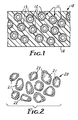
- FIG. 1 shows a schematic view of a composition comprising a plurality of susceptors of magnetically coupled radio frequency energy disposed in a matrix substantially non-reflective of radio frequency energy.
- FIG. 2 shows a schematic view of a plurality of susceptors comprising particles of a hot melt adhesive bearing a coating of a magnetic material on the surface thereof.
- composition 10 comprises (1) susceptors 11 comprising a non-magnetic substrate 12, which is in particulate form, bearing a thin magnetic coating 13 thereon, and (2) a matrix 14 that is substantially non-reflective of radio frequency energy, which matrix can be heated upon the compositions being subjected to radio frequency energy.
- Substrates can be made of such materials as glass, ceramic, polymer, or the like. It is preferred that the material of the substrate have sufficient strength to withstand processing conditions, such as, for example, compounding and extrusion.
- the surface of the substrate is continuous, so as to be able to receive and support a coating of a thin, continuous, magnetic film.
- the shape of the substrate can vary. Examples of shapes that are useful for this invention include spherical, spheroidal, ellipsoidal, granular, acicular, plates, flakes, and shapes that are irregular and non-uniform from substrate to substrate.
- the particles forming the substrates can be solid or hollow.
- the dimensions of the substrate can vary, but it is preferred that the major dimension be smaller than one centimeter, more preferably from 10 to 1,000 micrometers.
- the material for the coating for the substrate must be magnetic in nature, and it is preferable that the material have a large magnetic hysteresis loop.
- Inorganic materials suitable for preparing the magnetic coating include metals, such as iron, cobalt, and nickel, alloys thereof, such as stainless steel, amorphous metal alloys, and oxides of metals, such as ferrites.
- the coatings are sufficiently thick to form a continuous coating and to impart magnetism to the coated particle.
- the thickness of the coating can range from 1 to 1000 nm (10 to 10,000 ⁇ ), preferably, from 1 to 100 nm (10 to 1,000 ⁇ ), and more preferably, from 2 to 50 nm (20 to 500 ⁇ ). As a general rule, above a certain minimum thickness, as the thickness of the coating increases, the greater is the observed conversion of electromagnetic energy to heat.
- the heating efficiency of the susceptor of this invention is dependent on the magnetic properties of the coating. As the temperature of the coating approaches its Curie temperature, its magnetic properties decrease so that the material is no longer magnetic. At the Curie temperature, the material can no longer efficiently absorb induction energy. When the material cools to a temperature below its Curie temperature, it becomes magnetic again and will absorb induction energy. Control of Curie temperature can be used to limit the maximum temperature of the material being heated.
- the relatively narrow maximum temperature range of the composition of this invention is surprising because thin coatings of magnetic materials generally have a broad Curie temperature range. By appropriate choice of the coating material, a wide variety of limiting temperatures can be obtained. Examples of materials that can be used to provide an appropriate Curie temperature include magnetic metals, such as iron, cobalt, or nickel, in combination with selected amounts of metals or metalloids, such as silicon, phosphorous, or boron.
- Material to be heated by the susceptors of this invention i.e., material forming the matrix, must be substantially non-reflective of radio frequency energy.
- These materials can be solids, including powders, liquids, or gases.
- the matrix can be flowable or non-flowable.
- the susceptors can be mixed with the matrix material or the matrix material can be coated with the magnetic susceptor material.
- the susceptors can also just be laid-up on the matrix material.
- Matrix material suitable for this invention include polymers, waxes, silicone rubbers, heat shrinkable rubbers, and hot-melt adhesives.
- the susceptors of this invention have a number of advantages over susceptors of the prior art.
- the coated susceptors of this invention are lower in weight, are lower in cost because they contain less metal, are more easily dispersible in the matrix, and are more easily handled during processing than are susceptors previously known.
- the susceptors of this invention have heating efficiencies equal to or better than susceptors made of solid particulate materials.
- the susceptors of this invention can be made more transparent to X-rays than susceptors made of solid metal powders.
- coated needle-shaped or flat non-metallic substrates e.g., flakes
- flat coated particles such as coated mica flakes
- flakes can provide lower volume loadings than can spherical particles, but can still provide an equivalent or greater amount of heat.
- the susceptors of this invention can be used in a number of different ways. For example, they can be incorporated into a matrix such as a thin polymeric sheet or a ceramic dish and the matrix heated by an induction heater; they can be added to a liquid polymeric material, and the material subsequently cured in an induction heater; they can be admixed with a hot-melt adhesive powder or hot-melt adhesive particles, and an induction heater can then be used to melt the composition and thereafter form an adhesive bond.
- a matrix such as a thin polymeric sheet or a ceramic dish and the matrix heated by an induction heater
- they can be added to a liquid polymeric material, and the material subsequently cured in an induction heater
- they can be admixed with a hot-melt adhesive powder or hot-melt adhesive particles, and an induction heater can then be used to melt the composition and thereafter form an adhesive bond.
- coated microbubbles are used as susceptors in a matrix containing hot-melt adhesive powder, the microbubbles will impart light weight character to the composition to form a foamed adhesive or syntactic-foamed adhesive.
- Hot-melt adhesives admixed with susceptors can be applied to an article by coating the mixture on the surface of an article to be bonded, as for example, the top of a box or the flap of a package. After the contents are inserted into the box or package, the filled container can be placed in an induction heater with the portion thereof to be sealed held in place during the heating process.
- a particularly useful aspect of this mixture involves the bonding of separate pieces or portions of thermoplastic polymeric material, such as, for example, the free ends of thermoplastic polymeric tubing.
- hot-melt adhesive particles themselves can be used as the substrate of the susceptor.
- the hot-melt adhesive particles 21 can be directly coated with the thin-film coating 22.
- the adhesive particles 20 melt, flow into contact with other adhesive particles, and then subsequently cool to form a solid adhesive mass. Because the volume of metal present is very small, almost 100% of the mass is adhesive. The cohesive strength will be close to that of a hot-melt adhesive containing no added particles.
- a hot-melt adhesive powder suitable for this purpose is designated by the trademark EASTOBOND FA300, available from Eastman Chemical Products, Kingsport, Tennessee.
- the heating efficiency of the composition can be controlled by controlling the percentage of susceptors in the composition, the thickness of the composition, or both.
- the susceptors are also capable of being re-heated.
- Induction heatable susceptors complement microwave heatable susceptors.
- Coated susceptor particles that work well for one application do not necessarily work well for the other application.
- the coating of the coated particles must be magnetic to efficiently absorb induction heating energy, while non-magnetic coated particles work well as microwave susceptors.
- the thicker the magnetic coating the greater the energy absorption.
- the LEPEL T-2.5-1-MC-B3W induction heater used in the following examples was a 2.5 kilowatt unit having two frequency ranges, 2.5 to 5 MHz and 5 to 8 MHz.
- the coil dimensions, grid and tank circuit settings, and sample coupling determine the actual resonant frequency of the induction heater during operation. Full power was not normally used in the examples.
- the coil included 5 turns of 0.64 cm outer diameter copper tubing. The inner diameter of the coil was 3.18 cm and the length of the coil was 4.44 cm The coil was cooled by water.
- Glass microbubbles (760 g, S60/10000 SCOTCHLITE, Minnesota Mining and Manufacturing Company, St. Paul, Minnesota) having an average density of 0.60 g/cc were tumbled in a vacuum chamber while being sputter coated with #304 stainless steel vapor.
- the stainless steel target was a rectangular cathode (12.7 cm by 20.3 cm).
- the argon sputtering gas pressure was 0.4 Pa (3 millitorr).
- the background pressure was 0.4 to 1.3 x 10 -3 Pa (3 to 10 x 10 -3 millitorr).
- the operation was conducted for 420 minutes in the direct current planar magnetron mode at an applied power of 7.0 kilowatts.
- the coated particles were dark silver-gray in color.
- Number 304 stainless steel is known to be non-magnetic, but when it is sputtered, it forms a magnetic thin film coating.
- the coating was estimated to be 7.5 nm (75 ⁇ ) thick by the method,described in U.S. Patent No. 5 294 763.
- the average surface area of the particles can be determined using the Brunauer, Emmett, Teller method (BET), as described in T. Allen, Particle Size Measurement , 3rd edition, Chapman and Hall, 1981.
- BET Brunauer, Emmett, Teller method
- a composition was made by mixing the coated particles (10 volume percent) with RTV-11 silicone rubber, available from GE Silicones, Waterford, New York.
- a strip of the composition was placed in the coil of the LEPEL T-2.5-1-MC-B3W induction heater. The frequency was set to the 5 to 8 MHz range, the plate current was set to .30 amp, and the grid current was set to 93 milliamps.
- a LUXTRON 750 thermometry system with fiber optic probes was used to measure the temperature of the sample in the coil as a function of time. Automatic data acquisition and software were used to obtain a heating rate for the sample. The heating rate of the composition was 14°C per second.
- Example 1 The sample described in Example 1 was placed in the LEPEL induction heater set to the 2.5 to 5 MHz frequency range.
- the plate current was set to 0.79 amp, and the grid current was set to 230 milliamps.
- the heating rate of the composition was 13°C per second.
- Example 1 The coated particles described in Example 1 were formed into a composition with RTV-11 silicone rubber at a volume loading of 5%. A 2.22 cm x 6.35 cm x 1.7 mm piece of this composition was placed in the LEPEL induction heater set to the 5 to 8 MHz range. The heating rate of the composition was 7°C per second.
- Glass microbubbles (85 g, SCOTCHLITE S60/10000) were coated with #304 steel by the process described in Example 1, except that the duration of the coating process was 300 minutes.
- the thickness of the coating was 22.5nm (225 ⁇ ).
- These coated microbubbles were made into a composition with RTV-11 silicone rubber at a 5% volume loading, and a 2.22 cm x 6.35 cm x 1.8 mm piece thereof was placed in the LEPEL induction heater set to the 5 to 8 MHz range.
- the heating rate of the composition was 12°C per second.
- mice (540 g, SUZORITE 200HK, Suzorite Mica, Inc., Hunt Valley, Maryland), having an average density of 2.9 g/cc, were coated with #304 steel by the process described in Example 1, except that the duration of the coating process was 1080 minutes. The thickness of the coating was 10.5nm (105 ⁇ ). These coated flakes were made into a composition with RTV-11 silicone rubber at a volume loading of 5%. A 2.22 cm x 6.35 cm x 1.2 mm piece of this sample was placed in the LEPEL induction heater set to the 5 to 8 MHz range. The heating rate of the composition was 53°C per second.
- Nickel was coated onto glass microbubbles (9 g C15/250, SCOTCHLITE, Minnesota Mining and Manufacturing Company) having an average density of 0.15 g/cc by tumbling in a vacuum chamber with a source of nickel (TRIMAG, available from L.M. Simard, Santa Barbara, California).
- the operating conditions included a plasma current of 6 to 10 amps, a cathode potential of 750 to 1125 volts, and a cathode current of 0.22 to 0.33 amp.
- the thickness of the coating was 5.1nm (51 ⁇ ). These particles were mixed into two-part 5 minute epoxy (DEVCON, Devcon Corp., Danvers, Maryland) at a volume loading of 57%.
- DEVCON Devcon Corp., Danvers, Maryland
- a 5.08 cm x 2.39 cm x 0.94 mm piece of this sample was placed in the LEPEL induction heater set at the 5 to 8 MHz range. The heating rate of the composition was 13°C per second.
- Glass microbubbles (85 g, S60/1000 SCOTCHLITE) were coated with #304 steel by the process described in Example 1, except that the duration of the coating process was 180 minutes and the applied power was 0.8 kw. The thickness of the coating was 2 nm (20 ⁇ ).
- Half of this sample was then given an overcoat of aluminum suboxide in the same manner as the sputtering process of Example 1 except that an aluminum target was run at an applied power of 1.5 kw for a period of 180 minutes while oxygen was added to the chamber at a rate of 5 cc/min.
- the thus-formed insulating overcoat had the result of eliminating the bulk conductivity of the coated particles.
- Example 6 The nickel-coated particles of Example 6 were mixed into a plaster of Paris matrix at a loading of 10% by weight. Sufficient water was added to the matrix to facilitate mixing. The composition was shaped into a cylindrical sample (2.54 cm in diameter; 1.91 cm long) and allowed to dry overnight at 170°C. A Luxtron temperature probe was inserted into a small hole in the center of this sample. The sample was then placed in the LEPEL induction heater and heated under the conditions set forth in Table 1. In each case, the final temperature of the composition was between 331°C and 345°C, thereby indicating that heating of the sample is limited by the Curie temperature of the metal coating.
- Thin film coatings exhibit a broad Curie transition range, the magnetic susceptibility beginning to decrease at a temperature well below the Curie temperature. This accounts for the differences between the sample temperatures and the Curie temperature of bulk nickel metal, which is 354°C.
- Frequency range MHz
- Plate current amp
- Average heating rate °C/sec
- Final temperature °C) 2.5 to 5 .50 9 331 2.5 to 5 .80 14 340 5 to 8 .22 11 338 5 to 8 .30 12 345
- Mica (540 g, SUZORITE 200HK) was coated with #304 steel by the process described in Example 1. The coating duration was 422 minutes at a power of 7 kw. The thickness of the coating was 3.5nm (35 ⁇ ). These particles were mixed into powdered high density polyethylene (GM9255 HOSTALEN HDPE, Hoechst Celanese Corp., Pasadena, Texas) at a volume loading of 15%. The mixed powders were hot pressed to form a sheet having a thickness of about 0.6 mm. Pieces of this sheet were cut into strips.
- GM9255 HOSTALEN HDPE powdered high density polyethylene
- Pieces of two sizes of standard polyethylene tubing were selected; the smaller size tubing had an outer diameter of 0.95 cm, and the larger size tubing had an inner diameter of 0.95 cm, such that the larger size tubing fit over the smaller size tubing.
- a 0.95 cm wide strip of the coated particle/polyethylene composition was wrapped around a piece of the smaller tube near one end of it. The larger tubing was stretched and fit over this end, thereby providing two pieces of tubing joined by a strip of composition containing coated particles and polyethylene wrapped around the interface.
- the assembly was put into the coil of the LEPEL induction heater as described in Example 1 for 10 seconds.
- the composition was heated by the induction heater to its melting temperature.
- the induction heating also melted the polyethylene tubing at the interface, providing a melt bonding of the two pieces of polyethylene tubing.
- Adhesive particles (112 g, EASTOBOND FA300 Hot Melt Adhesive Powder, Eastman Chemical Products, Kingsport, Tennessee) having an average density of 1.25 g/cc were coated in the same manner as described in Example 1, except that the coating time was 310 minutes and the applied power was 0.5 kw. The thickness of the steel coating was 6.7nm (67 ⁇ ).
- a composition was made by mixing 47 volume percent of the coated particles into two part five-minute epoxy (DEVCON). A strip of the composition, approximately 2.22 cm x 5.08 cm x 2.0 mm, was placed in the LEPEL induction heater which had been set to the 5 to 8 MHz range and the heating rate was found to be 1.8°C per second. Uncoated adhesive particles, mixed into five minute epoxy as described above, did not heat at all in the induction heater.
Description
- This invention relates to articles capable of being heated by magnetically coupled radio frequency energy.
- Magnetic susceptors are used to convert energy derived from radio frequency induction heaters to heat energy at a point of application. For example, U.S. Patent No. 3,461,014 discloses a method for heat sealing and bonding predetermined sealing areas of two units of material, one of which has a heat-fusible plastic surface, comprising the steps of (1) positioning a deposit of fine, discrete susceptor particles selected from the chemical family of ferromagnetic oxides on one of said units at said predetermined sealing areas, (2) bringing said units of materials into opposed, interfacing relation with said deposit interposed therebetween and contiguous to said fusible plastic surface, (3) subjecting said susceptor particles to a magnetic induction field and thereby concentrating heat effect upon substantially only the plastic material immediately contiguous to said particles, and (4) bringing said units into firm contact.
- U.S. Patent No. 3,574,031 discloses a method of heat welding thermoplastic bodies comprising the steps of (1) forming a stratum of susceptor sealant by uniformly dispersing particles of a susceptor material selected from a group consisting of magnetically polar substances and electrically polar substances, excitable by a selected form of indirectly applied energy for raising the temperature of the susceptor material in a thermoplastic carrier compatible with the chemical families of the thermoplastic bodies to be welded, each of said particles having a maximum dimension less than the thickness of the stratum; (2) applying the stratum of susceptor sealant to the bodies in the area to be heat welded; and (3) exposing the susceptor sealant to the selected form of indirectly applied energy to generate heat therein sufficient to soften the carrier and cause the stratum to intimately weld the thermoplastic bodies.
- Bonding by induction heating can be used to seal bags and pouches, seal window panes, bind books, and the like.
- Induction heating can be used in situations where microwave heating is not suitable, such as, for example, in cases where the materials to be bonded absorb microwave energy, such as polar polymers, wood, or materials containing non-magnetic conductive particles. In these situations, it may be desirable to heat the bond area only and not the material to be bonded.
- This invention provides a composition comprising: (1) a susceptor of magnetically coupled radio frequency energy comprising a non-magnetic particulate substrate, e.g., an electrically insulative material in particulate form, bearing an inorganic, magnetic, continuous thin-film coating, e.g., a magnetic inorganic film as prepared by sputter-coating, and (2) a matrix that is substantially non-reflective of radio frequency energy, e.g., silicone rubber, which matrix can be heated upon the composition's being subjected to radio frequency energy.
- Previously, magnetic susceptors that have been used as energy transfer agents with induction heaters have been in the form of solid particles. Surprisingly, it has been discovered that thin magnetic coatings on non-magnetic particles provide energy transfer with induction heaters equal to or better than many commonly used solid susceptor particles. Moreover, it has been discovered that the temperature of the composition of this invention can be regulated so as to not exceed a predetermined temperature, thereby minimizing decomposition of the matrix on account of overheating. Furthermore, the susceptors have high heating efficiencies, are of low weight, are of low cost, and are easily handlable.
- FIG. 1 shows a schematic view of a composition comprising a plurality of susceptors of magnetically coupled radio frequency energy disposed in a matrix substantially non-reflective of radio frequency energy.
- FIG. 2 shows a schematic view of a plurality of susceptors comprising particles of a hot melt adhesive bearing a coating of a magnetic material on the surface thereof.
- In a preferred embodiment of this invention, as shown in FIG. 1,
composition 10 comprises (1) susceptors 11 comprising anon-magnetic substrate 12, which is in particulate form, bearing a thinmagnetic coating 13 thereon, and (2) amatrix 14 that is substantially non-reflective of radio frequency energy, which matrix can be heated upon the compositions being subjected to radio frequency energy. - Substrates can be made of such materials as glass, ceramic, polymer, or the like. It is preferred that the material of the substrate have sufficient strength to withstand processing conditions, such as, for example, compounding and extrusion. Preferably, the surface of the substrate is continuous, so as to be able to receive and support a coating of a thin, continuous, magnetic film. The shape of the substrate can vary. Examples of shapes that are useful for this invention include spherical, spheroidal, ellipsoidal, granular, acicular, plates, flakes, and shapes that are irregular and non-uniform from substrate to substrate. The particles forming the substrates can be solid or hollow. The dimensions of the substrate can vary, but it is preferred that the major dimension be smaller than one centimeter, more preferably from 10 to 1,000 micrometers.
- The material for the coating for the substrate must be magnetic in nature, and it is preferable that the material have a large magnetic hysteresis loop. Inorganic materials suitable for preparing the magnetic coating include metals, such as iron, cobalt, and nickel, alloys thereof, such as stainless steel, amorphous metal alloys, and oxides of metals, such as ferrites. The coatings are sufficiently thick to form a continuous coating and to impart magnetism to the coated particle. The thickness of the coating can range from 1 to 1000 nm (10 to 10,000 Å), preferably, from 1 to 100 nm (10 to 1,000 Å), and more preferably, from 2 to 50 nm (20 to 500 Å). As a general rule, above a certain minimum thickness, as the thickness of the coating increases, the greater is the observed conversion of electromagnetic energy to heat.
- The heating efficiency of the susceptor of this invention is dependent on the magnetic properties of the coating. As the temperature of the coating approaches its Curie temperature, its magnetic properties decrease so that the material is no longer magnetic. At the Curie temperature, the material can no longer efficiently absorb induction energy. When the material cools to a temperature below its Curie temperature, it becomes magnetic again and will absorb induction energy. Control of Curie temperature can be used to limit the maximum temperature of the material being heated. The relatively narrow maximum temperature range of the composition of this invention is surprising because thin coatings of magnetic materials generally have a broad Curie temperature range. By appropriate choice of the coating material, a wide variety of limiting temperatures can be obtained. Examples of materials that can be used to provide an appropriate Curie temperature include magnetic metals, such as iron, cobalt, or nickel, in combination with selected amounts of metals or metalloids, such as silicon, phosphorous, or boron.
- Material to be heated by the susceptors of this invention, i.e., material forming the matrix, must be substantially non-reflective of radio frequency energy. These materials can be solids, including powders, liquids, or gases. In other words, the matrix can be flowable or non-flowable. The susceptors can be mixed with the matrix material or the matrix material can be coated with the magnetic susceptor material. The susceptors can also just be laid-up on the matrix material. Matrix material suitable for this invention include polymers, waxes, silicone rubbers, heat shrinkable rubbers, and hot-melt adhesives.
- The susceptors of this invention have a number of advantages over susceptors of the prior art. The coated susceptors of this invention are lower in weight, are lower in cost because they contain less metal, are more easily dispersible in the matrix, and are more easily handled during processing than are susceptors previously known. Moreover, the susceptors of this invention have heating efficiencies equal to or better than susceptors made of solid particulate materials. The susceptors of this invention can be made more transparent to X-rays than susceptors made of solid metal powders.
- It has been found that certain coated needle-shaped or flat non-metallic substrates, e.g., flakes, though solid, can have a lower weight than conventional solid metal particles. In addition, flat coated particles, such as coated mica flakes, provide heat more effectively than do coated spherical particles; accordingly, flakes can provide lower volume loadings than can spherical particles, but can still provide an equivalent or greater amount of heat.
- The susceptors of this invention can be used in a number of different ways. For example, they can be incorporated into a matrix such as a thin polymeric sheet or a ceramic dish and the matrix heated by an induction heater; they can be added to a liquid polymeric material, and the material subsequently cured in an induction heater; they can be admixed with a hot-melt adhesive powder or hot-melt adhesive particles, and an induction heater can then be used to melt the composition and thereafter form an adhesive bond.
- If coated microbubbles are used as susceptors in a matrix containing hot-melt adhesive powder, the microbubbles will impart light weight character to the composition to form a foamed adhesive or syntactic-foamed adhesive.
- Hot-melt adhesives admixed with susceptors can be applied to an article by coating the mixture on the surface of an article to be bonded, as for example, the top of a box or the flap of a package. After the contents are inserted into the box or package, the filled container can be placed in an induction heater with the portion thereof to be sealed held in place during the heating process. A particularly useful aspect of this mixture involves the bonding of separate pieces or portions of thermoplastic polymeric material, such as, for example, the free ends of thermoplastic polymeric tubing.
- In another aspect of this invention, as shown in FIG. 2, hot-melt adhesive particles themselves can be used as the substrate of the susceptor. The hot-melt
adhesive particles 21 can be directly coated with the thin-film coating 22. When heated by an induction heater, theadhesive particles 20 melt, flow into contact with other adhesive particles, and then subsequently cool to form a solid adhesive mass. Because the volume of metal present is very small, almost 100% of the mass is adhesive. The cohesive strength will be close to that of a hot-melt adhesive containing no added particles. A hot-melt adhesive powder suitable for this purpose is designated by the trademark EASTOBOND FA300, available from Eastman Chemical Products, Kingsport, Tennessee. - The heating efficiency of the composition can be controlled by controlling the percentage of susceptors in the composition, the thickness of the composition, or both. The susceptors are also capable of being re-heated.
- Induction heatable susceptors complement microwave heatable susceptors. Coated susceptor particles that work well for one application do not necessarily work well for the other application. The coating of the coated particles must be magnetic to efficiently absorb induction heating energy, while non-magnetic coated particles work well as microwave susceptors. For induction heating, in general, the thicker the magnetic coating, the greater the energy absorption.
- The following non-limiting examples serve to further illustrate the invention. The LEPEL T-2.5-1-MC-B3W induction heater used in the following examples was a 2.5 kilowatt unit having two frequency ranges, 2.5 to 5 MHz and 5 to 8 MHz. The coil dimensions, grid and tank circuit settings, and sample coupling determine the actual resonant frequency of the induction heater during operation. Full power was not normally used in the examples. The coil included 5 turns of 0.64 cm outer diameter copper tubing. The inner diameter of the coil was 3.18 cm and the length of the coil was 4.44 cm The coil was cooled by water.
- Glass microbubbles (760 g, S60/10000 SCOTCHLITE, Minnesota Mining and Manufacturing Company, St. Paul, Minnesota) having an average density of 0.60 g/cc were tumbled in a vacuum chamber while being sputter coated with #304 stainless steel vapor. The stainless steel target was a rectangular cathode (12.7 cm by 20.3 cm). The argon sputtering gas pressure was 0.4 Pa (3 millitorr). The background pressure was 0.4 to 1.3 x 10⁻³ Pa (3 to 10 x 10-3 millitorr). The operation was conducted for 420 minutes in the direct current planar magnetron mode at an applied power of 7.0 kilowatts.
- The coated particles were dark silver-gray in color. Number 304 stainless steel is known to be non-magnetic, but when it is sputtered, it forms a magnetic thin film coating. The coating was estimated to be 7.5 nm (75 Å) thick by the method,described in U.S. Patent No. 5 294 763.
- The thickness of the coating on a spherical particle is calculated from the weight percent of the coating using the following equation:
- t
- represents the thickness of the coating in Angstroms,
- W
- represents the weight percent of the coating on the particle, based on total weight of the particle,
- D
- represents the density of the coating in g/cc, and
- S
- represents the average surface area of the particles in m2/g.
- The average surface area of the particles can be determined using the Brunauer, Emmett, Teller method (BET), as described in T. Allen, Particle Size Measurement, 3rd edition, Chapman and Hall, 1981.
- A composition was made by mixing the coated particles (10 volume percent) with RTV-11 silicone rubber, available from GE Silicones, Waterford, New York. A strip of the composition, approximately 2.22 cm x 6.35 cm x 2.1 mm, was placed in the coil of the LEPEL T-2.5-1-MC-B3W induction heater. The frequency was set to the 5 to 8 MHz range, the plate current was set to .30 amp, and the grid current was set to 93 milliamps. A LUXTRON 750 thermometry system with fiber optic probes was used to measure the temperature of the sample in the coil as a function of time. Automatic data acquisition and software were used to obtain a heating rate for the sample. The heating rate of the composition was 14°C per second.
- The sample described in Example 1 was placed in the LEPEL induction heater set to the 2.5 to 5 MHz frequency range. The plate current was set to 0.79 amp, and the grid current was set to 230 milliamps. The heating rate of the composition was 13°C per second.
- The coated particles described in Example 1 were formed into a composition with RTV-11 silicone rubber at a volume loading of 5%. A 2.22 cm x 6.35 cm x 1.7 mm piece of this composition was placed in the LEPEL induction heater set to the 5 to 8 MHz range. The heating rate of the composition was 7°C per second.
- Glass microbubbles (85 g, SCOTCHLITE S60/10000) were coated with #304 steel by the process described in Example 1, except that the duration of the coating process was 300 minutes. The thickness of the coating was 22.5nm (225 Å). These coated microbubbles were made into a composition with RTV-11 silicone rubber at a 5% volume loading, and a 2.22 cm x 6.35 cm x 1.8 mm piece thereof was placed in the LEPEL induction heater set to the 5 to 8 MHz range. The heating rate of the composition was 12°C per second.
- Mica flakes (540 g, SUZORITE 200HK, Suzorite Mica, Inc., Hunt Valley, Maryland), having an average density of 2.9 g/cc, were coated with #304 steel by the process described in Example 1, except that the duration of the coating process was 1080 minutes. The thickness of the coating was 10.5nm (105 Å). These coated flakes were made into a composition with RTV-11 silicone rubber at a volume loading of 5%. A 2.22 cm x 6.35 cm x 1.2 mm piece of this sample was placed in the LEPEL induction heater set to the 5 to 8 MHz range. The heating rate of the composition was 53°C per second.
- Nickel was coated onto glass microbubbles (9 g C15/250, SCOTCHLITE, Minnesota Mining and Manufacturing Company) having an average density of 0.15 g/cc by tumbling in a vacuum chamber with a source of nickel (TRIMAG, available from L.M. Simard, Santa Barbara, California). The operating conditions included a plasma current of 6 to 10 amps, a cathode potential of 750 to 1125 volts, and a cathode current of 0.22 to 0.33 amp. The thickness of the coating was 5.1nm (51 Å). These particles were mixed into two-part 5 minute epoxy (DEVCON, Devcon Corp., Danvers, Maryland) at a volume loading of 57%. A 5.08 cm x 2.39 cm x 0.94 mm piece of this sample was placed in the LEPEL induction heater set at the 5 to 8 MHz range. The heating rate of the composition was 13°C per second.
- Glass microbubbles (85 g, S60/1000 SCOTCHLITE) were coated with #304 steel by the process described in Example 1, except that the duration of the coating process was 180 minutes and the applied power was 0.8 kw. The thickness of the coating was 2 nm (20 Å). Half of this sample was then given an overcoat of aluminum suboxide in the same manner as the sputtering process of Example 1 except that an aluminum target was run at an applied power of 1.5 kw for a period of 180 minutes while oxygen was added to the chamber at a rate of 5 cc/min. The thus-formed insulating overcoat had the result of eliminating the bulk conductivity of the coated particles. Each of these samples were made into a composition with 5 minute epoxy (SCOTCHCAST, Minnesota Mining and Manufacturing Company) at a volume loading of 50%. A 2.54 cm x 2.54 cm x 1.8 mm piece of both of these samples was placed in the LEPEL induction heater set at the 5 to 8 MHz range. For the sample wherein the particles were coated with steel only, the heating rate was 9.2°C/sec. For the sample wherein the particles were coated with both aluminum suboxide and steel coatings, the heating rate was 9.3°C/sec. It was concluded that the insulating overcoat did not affect the heating rate of the composition.
- The nickel-coated particles of Example 6 were mixed into a plaster of Paris matrix at a loading of 10% by weight. Sufficient water was added to the matrix to facilitate mixing. The composition was shaped into a cylindrical sample (2.54 cm in diameter; 1.91 cm long) and allowed to dry overnight at 170°C. A Luxtron temperature probe was inserted into a small hole in the center of this sample. The sample was then placed in the LEPEL induction heater and heated under the conditions set forth in Table 1. In each case, the final temperature of the composition was between 331°C and 345°C, thereby indicating that heating of the sample is limited by the Curie temperature of the metal coating.
- Thin film coatings exhibit a broad Curie transition range, the magnetic susceptibility beginning to decrease at a temperature well below the Curie temperature. This accounts for the differences between the sample temperatures and the Curie temperature of bulk nickel metal, which is 354°C.
Frequency range
(MHz)Plate current
(amp)Average heating rate
(°C/sec)Final temperature
(°C)2.5 to 5 .50 9 331 2.5 to 5 .80 14 340 5 to 8 .22 11 338 5 to 8 .30 12 345 - Mica (540 g, SUZORITE 200HK) was coated with #304 steel by the process described in Example 1. The coating duration was 422 minutes at a power of 7 kw. The thickness of the coating was 3.5nm (35 Å). These particles were mixed into powdered high density polyethylene (GM9255 HOSTALEN HDPE, Hoechst Celanese Corp., Pasadena, Texas) at a volume loading of 15%. The mixed powders were hot pressed to form a sheet having a thickness of about 0.6 mm. Pieces of this sheet were cut into strips.
- Pieces of two sizes of standard polyethylene tubing were selected; the smaller size tubing had an outer diameter of 0.95 cm, and the larger size tubing had an inner diameter of 0.95 cm, such that the larger size tubing fit over the smaller size tubing. A 0.95 cm wide strip of the coated particle/polyethylene composition was wrapped around a piece of the smaller tube near one end of it. The larger tubing was stretched and fit over this end, thereby providing two pieces of tubing joined by a strip of composition containing coated particles and polyethylene wrapped around the interface. The assembly was put into the coil of the LEPEL induction heater as described in Example 1 for 10 seconds. The composition was heated by the induction heater to its melting temperature. The induction heating also melted the polyethylene tubing at the interface, providing a melt bonding of the two pieces of polyethylene tubing.
- Adhesive particles (112 g, EASTOBOND FA300 Hot Melt Adhesive Powder, Eastman Chemical Products, Kingsport, Tennessee) having an average density of 1.25 g/cc were coated in the same manner as described in Example 1, except that the coating time was 310 minutes and the applied power was 0.5 kw. The thickness of the steel coating was 6.7nm (67 Å). A composition was made by mixing 47 volume percent of the coated particles into two part five-minute epoxy (DEVCON). A strip of the composition, approximately 2.22 cm x 5.08 cm x 2.0 mm, was placed in the LEPEL induction heater which had been set to the 5 to 8 MHz range and the heating rate was found to be 1.8°C per second. Uncoated adhesive particles, mixed into five minute epoxy as described above, did not heat at all in the induction heater.
Claims (9)
- A composition that can be heated at a controlled efficiency by an induction heater, said composition comprising (a) a plurality of susceptors having the capability of absorbing magnetically coupled radio frequency energy, each of said susceptors comprising a non-magnetic particle having a surface bearing an inorganic, magnetic, continuous thin-film coating as prepared by sputter-coating, which magnetic film absorbs magnetically coupled radio frequency energy, said susceptors being disposed in (b) a matrix non-reflective of radio frequency energy, which matrix is capable of being heated when said composition is subjected to magnetically coupled radio frequency energy.
- The composition of claim 1, wherein said susceptors are spherical, spheroidal, ellipsoidal, granular, acicular, plates, flakes or irregular in shape.
- The composition of claim 2, wherein said flakes are mica.
- The composition of claim 1, wherein said film has a thickness of from 1 to 1000 nm (10 to 10,000 Å).
- The composition of claim 1, further comprising an electrically insulating coating deposited over said magnetic film.
- The composition of claim 1, wherein the non-magnetic particles comprise spheres or flakes that have a continuous surface that receives and supports said magnetic film.
- A method of heating a material, said method comprising (a) disposing in the material a plurality of susceptors having the capability of absorbing magnetically coupled radio frequency energy, each of said susceptors comprising a non-magnetic particle having a surface bearing an inorganic, magnetic, continuous thin-film coating as prepared by sputter-coating, which magnetic film absorbs magnetically coupled radio frequency energy, the material being non-reflective of radio frequency energy; and (b) subjecting the mixture of material and said susceptors to magnetically coupled radio frequency energy to heat the mixture to a desired temperature.
- An article comprising a hot-melt adhesive particle bearing on the surface thereof an inorganic, magnetic, continuous thin-film coating as prepared by sputter-coating, which magnetic film absorbs magnetically coupled radio frequency energy so as to heat the particle and cause said particle to melt and flow.
- A method of preparing a hot-melt adhesive capable of being heated by magnetically coupled radio frequency energy, said method comprising the steps of (a) providing non-magnetic particles having a surface; (b) depositing an inorganic, magnetic, continuous thin-film coating as prepared by sputter-coating and having a thickness of 1 to 1000 nm onto the surface of each of said non-magnetic particles, said film being capable of absorbing magnetically coupled radio frequency energy; and (c) incorporating said non-magnetic particles bearing said magnetic film into a hot-melt adhesive matrix.
Applications Claiming Priority (2)
| Application Number | Priority Date | Filing Date | Title |
|---|---|---|---|
| US66897491A | 1991-03-13 | 1991-03-13 | |
| US668974 | 1991-03-13 |
Publications (2)
| Publication Number | Publication Date |
|---|---|
| EP0503794A1 EP0503794A1 (en) | 1992-09-16 |
| EP0503794B1 true EP0503794B1 (en) | 2002-07-31 |
Family
ID=24684514
Family Applications (1)
| Application Number | Title | Priority Date | Filing Date |
|---|---|---|---|
| EP92301540A Expired - Lifetime EP0503794B1 (en) | 1991-03-13 | 1992-02-24 | Radio frequency induction heatable compositions |
Country Status (6)
| Country | Link |
|---|---|
| US (2) | US5837088A (en) |
| EP (1) | EP0503794B1 (en) |
| JP (1) | JP3340758B2 (en) |
| KR (1) | KR920017800A (en) |
| AU (2) | AU656556B2 (en) |
| DE (1) | DE69232702T2 (en) |
Families Citing this family (93)
| Publication number | Priority date | Publication date | Assignee | Title |
|---|---|---|---|---|
| US5245151A (en) * | 1989-04-07 | 1993-09-14 | Minnesota Mining And Manufacturing Company | Method and article for microwave bonding of splice closure |
| CA2011740A1 (en) * | 1989-04-07 | 1990-10-07 | Glen Connell | Microwave heatable materials |
| WO1995004655A2 (en) * | 1993-08-06 | 1995-02-16 | Minnesota Mining And Manufacturing Company | Chlorine-free multilayered film medical device assemblies |
| US5710413A (en) * | 1995-03-29 | 1998-01-20 | Minnesota Mining And Manufacturing Company | H-field electromagnetic heating system for fusion bonding |
| US6037180A (en) * | 1996-03-08 | 2000-03-14 | Minnesota Mining And Manufacturing Company | Method for measuring the quantity of a polymeric or pre-polymeric composition |
| GB9612882D0 (en) | 1996-06-20 | 1996-08-21 | Dunlop Ltd | Densification of a porous structure |
| AU4066997A (en) * | 1996-08-16 | 1998-03-06 | Pharmacia Biotech Inc. | Device and methods for remotely induced thermal transduction in chemical and biochemical reactions |
| US5847038A (en) * | 1996-09-03 | 1998-12-08 | Xerox Corporation | Polymer processes |
| WO1998038243A1 (en) * | 1997-02-28 | 1998-09-03 | Johnson Robert Harlan Jr | High efficiency heating agents |
| US6348679B1 (en) * | 1998-03-17 | 2002-02-19 | Ameritherm, Inc. | RF active compositions for use in adhesion, bonding and coating |
| US6376619B1 (en) * | 1998-04-13 | 2002-04-23 | 3M Innovative Properties Company | High density, miniaturized arrays and methods of manufacturing same |
| US6395149B1 (en) | 1998-06-30 | 2002-05-28 | 3M Innovative Properties Company | Method of making light colored, electrically conductive coated particles |
| US6143405A (en) * | 1998-06-30 | 2000-11-07 | 3M Innovative Properties Company | Light colored, electrically conductive coated particles and composites made therefrom |
| JP2002524300A (en) * | 1998-09-04 | 2002-08-06 | ザ・グッドイヤー・タイヤ・アンド・ラバー・カンパニー | Tire component capable of induction vulcanization and method for selective vulcanization of said component |
| US6660122B1 (en) | 1998-09-04 | 2003-12-09 | The Goodyear Tire & Rubber Company | Induction curable tire components and methods of selectively curing such components |
| KR20000077221A (en) | 1999-05-12 | 2000-12-26 | 구마모토 마사히로 | Bladder for vulcanizer, vulcanizer using the same and vulcanizing-molding method |
| US6395483B1 (en) | 1999-09-02 | 2002-05-28 | 3M Innovative Properties Company | Arrays with mask layers |
| JP2001079851A (en) * | 1999-09-17 | 2001-03-27 | Kobe Steel Ltd | Vulcanizer |
| US6649888B2 (en) | 1999-09-23 | 2003-11-18 | Codaco, Inc. | Radio frequency (RF) heating system |
| CA2392078C (en) | 1999-11-03 | 2005-02-22 | Nexicor Llc | Hand held induction tool |
| US6482638B1 (en) * | 1999-12-09 | 2002-11-19 | 3M Innovative Properties Company | Heat-relaxable substrates and arrays |
| US6497676B1 (en) | 2000-02-10 | 2002-12-24 | Baxter International | Method and apparatus for monitoring and controlling peritoneal dialysis therapy |
| US6881538B1 (en) | 2000-03-05 | 2005-04-19 | 3M Innovative Properties Company | Array comprising diamond-like glass film |
| US6562448B1 (en) | 2000-04-06 | 2003-05-13 | 3M Innovative Properties Company | Low density dielectric having low microwave loss |
| US7141768B2 (en) | 2000-04-28 | 2006-11-28 | Nexicor, Llc | Fastening device |
| US6492133B1 (en) | 2000-05-01 | 2002-12-10 | 3M Innovative Properties Company | Reflective disc assay devices, systems and methods |
| US6734401B2 (en) | 2000-06-28 | 2004-05-11 | 3M Innovative Properties Company | Enhanced sample processing devices, systems and methods |
| US6627159B1 (en) * | 2000-06-28 | 2003-09-30 | 3M Innovative Properties Company | Centrifugal filling of sample processing devices |
| US6720187B2 (en) * | 2000-06-28 | 2004-04-13 | 3M Innovative Properties Company | Multi-format sample processing devices |
| CA2412275C (en) | 2000-06-28 | 2009-12-08 | 3M Innovative Properties Company | Enhanced sample processing devices, systems and methods |
| JP3723927B2 (en) * | 2000-07-11 | 2005-12-07 | 日本ライナー株式会社 | Method for curing epoxy resin in a short time and electromagnetic wave absorption method using cured epoxy resin obtained by the curing method |
| US8097471B2 (en) * | 2000-11-10 | 2012-01-17 | 3M Innovative Properties Company | Sample processing devices |
| US6783838B2 (en) | 2001-04-30 | 2004-08-31 | 3M Innovative Properties Company | Coated film laminate having an ionic surface |
| WO2004058405A1 (en) * | 2001-05-02 | 2004-07-15 | 3M Innovative Properties Company | Sample processing device with resealable process chamber |
| US7063978B2 (en) | 2001-11-01 | 2006-06-20 | 3M Innovative Properties Company | Coated film laminate having an electrically conductive surface |
| US6889468B2 (en) * | 2001-12-28 | 2005-05-10 | 3M Innovative Properties Company | Modular systems and methods for using sample processing devices |
| US20030125662A1 (en) | 2002-01-03 | 2003-07-03 | Tuan Bui | Method and apparatus for providing medical treatment therapy based on calculated demand |
| US6967315B2 (en) * | 2002-06-12 | 2005-11-22 | Steris Inc. | Method for vaporizing a fluid using an electromagnetically responsive heating apparatus |
| US7238164B2 (en) | 2002-07-19 | 2007-07-03 | Baxter International Inc. | Systems, methods and apparatuses for pumping cassette-based therapies |
| USRE40722E1 (en) | 2002-09-27 | 2009-06-09 | Surmodics, Inc. | Method and apparatus for coating of substrates |
| US7507376B2 (en) * | 2002-12-19 | 2009-03-24 | 3M Innovative Properties Company | Integrated sample processing devices |
| US7932090B2 (en) * | 2004-08-05 | 2011-04-26 | 3M Innovative Properties Company | Sample processing device positioning apparatus and methods |
| US7763210B2 (en) * | 2005-07-05 | 2010-07-27 | 3M Innovative Properties Company | Compliant microfluidic sample processing disks |
| US7323660B2 (en) * | 2005-07-05 | 2008-01-29 | 3M Innovative Properties Company | Modular sample processing apparatus kits and modules |
| US7754474B2 (en) * | 2005-07-05 | 2010-07-13 | 3M Innovative Properties Company | Sample processing device compression systems and methods |
| US7968823B2 (en) * | 2006-06-07 | 2011-06-28 | Engineered Glass Products, Llc | Wireless inductive coupling assembly for a heated glass panel |
| US8197452B2 (en) * | 2006-07-28 | 2012-06-12 | Becton, Dickinson And Company | Vascular access device non-adhering surfaces |
| TW200844420A (en) * | 2006-12-22 | 2008-11-16 | 3M Innovative Properties Co | Enhanced sample processing devices, systems and methods |
| WO2008080049A2 (en) | 2006-12-22 | 2008-07-03 | 3M Innovative Properties Company | Thermal transfer methods and structures for microfluidic systems |
| US8870812B2 (en) | 2007-02-15 | 2014-10-28 | Baxter International Inc. | Dialysis system having video display with ambient light adjustment |
| US7731689B2 (en) | 2007-02-15 | 2010-06-08 | Baxter International Inc. | Dialysis system having inductive heating |
| US20100179412A1 (en) * | 2007-02-15 | 2010-07-15 | Koninklijke Philips Electronics N.V. | Arrangement for magnetic particle imaging, method for influencing and/or detecting magnetic particles and magnetic particle |
| US8558964B2 (en) | 2007-02-15 | 2013-10-15 | Baxter International Inc. | Dialysis system having display with electromagnetic compliance (“EMC”) seal |
| US8361023B2 (en) | 2007-02-15 | 2013-01-29 | Baxter International Inc. | Dialysis system with efficient battery back-up |
| US7998115B2 (en) | 2007-02-15 | 2011-08-16 | Baxter International Inc. | Dialysis system having optical flowrate detection |
| DE102007059812A1 (en) * | 2007-12-11 | 2009-06-18 | Multivac Sepp Haggenmüller Gmbh & Co. Kg | Packaging machine with induction heating |
| US9364349B2 (en) | 2008-04-24 | 2016-06-14 | Surmodics, Inc. | Coating application system with shaped mandrel |
| WO2009134902A1 (en) * | 2008-04-30 | 2009-11-05 | Altarock Energy, Inc. | System and method for use of pressure actuated collapsing capsules suspended in a thermally expanding fluid in a subterranean containment space |
| USD638550S1 (en) | 2009-11-13 | 2011-05-24 | 3M Innovative Properties Company | Sample processing disk cover |
| USD638951S1 (en) | 2009-11-13 | 2011-05-31 | 3M Innovative Properties Company | Sample processing disk cover |
| USD667561S1 (en) | 2009-11-13 | 2012-09-18 | 3M Innovative Properties Company | Sample processing disk cover |
| US8834792B2 (en) | 2009-11-13 | 2014-09-16 | 3M Innovative Properties Company | Systems for processing sample processing devices |
| US9328015B2 (en) * | 2010-03-19 | 2016-05-03 | Owens-Brockway Glass Container Inc. | Curing coatings on glass containers |
| JP5808490B2 (en) | 2011-09-06 | 2015-11-10 | ブリティッシュ アメリカン タバコ (インヴェストメンツ) リミテッドBritish Americantobacco (Investments) Limited | Smoking material heating |
| JP5709731B2 (en) * | 2011-11-17 | 2015-04-30 | アイシン化工株式会社 | Microwave resin welded body and welding method using the same |
| JP6218748B2 (en) | 2011-12-22 | 2017-10-25 | スリーエム イノベイティブ プロパティズ カンパニー | Filter media containing metal-containing fine particles |
| MX351261B (en) | 2012-06-01 | 2017-10-06 | Surmodics Inc | Apparatus and method for coating balloon catheters. |
| US9827401B2 (en) | 2012-06-01 | 2017-11-28 | Surmodics, Inc. | Apparatus and methods for coating medical devices |
| US8959690B2 (en) | 2012-06-29 | 2015-02-24 | Nike, Inc. | Induction heating apparatuses and processes for footwear manufacturing |
| US9986787B2 (en) | 2012-06-29 | 2018-06-05 | Nike, Inc. | Induction heating apparatuses and processes for footwear manufacturing |
| GB201217067D0 (en) | 2012-09-25 | 2012-11-07 | British American Tobacco Co | Heating smokable material |
| US11090468B2 (en) | 2012-10-25 | 2021-08-17 | Surmodics, Inc. | Apparatus and methods for coating medical devices |
| US9283350B2 (en) | 2012-12-07 | 2016-03-15 | Surmodics, Inc. | Coating apparatus and methods |
| CN104185329B (en) * | 2013-05-22 | 2016-05-11 | 美的集团股份有限公司 | Coil panel assembly and the electromagnetic oven with it |
| KR101667177B1 (en) * | 2014-05-21 | 2016-10-24 | 필립모리스 프로덕츠 에스.에이. | Aerosol-generating article with multi-material susceptor |
| WO2016032795A1 (en) | 2014-08-29 | 2016-03-03 | 3M Innovative Properties Company | Inductively curable composition |
| US20170055575A1 (en) * | 2015-08-31 | 2017-03-02 | British American Tobacco (Investments) Limited | Material for use with apparatus for heating smokable material |
| US20170055584A1 (en) | 2015-08-31 | 2017-03-02 | British American Tobacco (Investments) Limited | Article for use with apparatus for heating smokable material |
| US11924930B2 (en) | 2015-08-31 | 2024-03-05 | Nicoventures Trading Limited | Article for use with apparatus for heating smokable material |
| US20170119047A1 (en) | 2015-10-30 | 2017-05-04 | British American Tobacco (Investments) Limited | Article for Use with Apparatus for Heating Smokable Material |
| US20170119046A1 (en) | 2015-10-30 | 2017-05-04 | British American Tobacco (Investments) Limited | Apparatus for Heating Smokable Material |
| JP6582881B2 (en) * | 2015-10-30 | 2019-10-02 | 東洋インキScホールディングス株式会社 | Hot melt adhesive sheet for electromagnetic induction heating, adhesive structure using the same, and method for producing adhesive structure |
| JP6582904B2 (en) * | 2015-11-12 | 2019-10-02 | 東洋インキScホールディングス株式会社 | Hot melt adhesive sheet for electromagnetic induction heating, adhesive structure using the same, and method for producing adhesive structure |
| DE102016206121A1 (en) * | 2016-04-13 | 2017-10-19 | Volkswagen Aktiengesellschaft | Method for producing a cooling jacket provided for an electrical machine and cooling jacket for an electrical machine |
| DE102017113158A1 (en) * | 2017-06-14 | 2018-12-20 | Rational Aktiengesellschaft | Cooking appliance |
| US11179516B2 (en) | 2017-06-22 | 2021-11-23 | Baxter International Inc. | Systems and methods for incorporating patient pressure into medical fluid delivery |
| EP3727842A4 (en) | 2017-12-22 | 2021-09-15 | Espinosa Duran, David Jose | Recyclable or compostable film replacements of plastic aluminum laminate packaging |
| WO2020112816A1 (en) | 2018-11-29 | 2020-06-04 | Surmodics, Inc. | Apparatus and methods for coating medical devices |
| US11819590B2 (en) | 2019-05-13 | 2023-11-21 | Surmodics, Inc. | Apparatus and methods for coating medical devices |
| EP3772403A1 (en) * | 2019-08-06 | 2021-02-10 | The Boeing Company | Remote detection of induction weld temperature |
| CN111618414A (en) * | 2020-04-26 | 2020-09-04 | 郭波 | Material electromagnetic connection method |
| DE102021116139B4 (en) * | 2021-06-22 | 2023-07-20 | VSM . Vereinigte Schmirgel- und Maschinen-Fabriken Aktiengesellschaft | Abrasive and method of making the abrasive |
| WO2023064741A1 (en) * | 2021-10-13 | 2023-04-20 | Board Of Supervisors Of Louisiana State University And Agricultural And Mechanical College | Low-temperature plastic depolymerization |
Citations (6)
| Publication number | Priority date | Publication date | Assignee | Title |
|---|---|---|---|---|
| US3461014A (en) * | 1964-06-11 | 1969-08-12 | Albert L James | Magnetic induction method for heat-sealing and bonding predetermined sealing areas |
| GB1212186A (en) * | 1966-11-18 | 1970-11-11 | Atomic Energy Authority Uk | Improvements in or relating to plastics compositions |
| GB1308603A (en) * | 1969-03-13 | 1973-02-21 | Ballotini Europ Deutschland Gm | Metal coated particles and the production thereof |
| US4438179A (en) * | 1982-02-03 | 1984-03-20 | The Dow Chemical Company | Resin particles with magnetic particles bonded to surface |
| JPS6286055A (en) * | 1985-10-09 | 1987-04-20 | Toyota Central Res & Dev Lab Inc | Electromagnetic wave shielding material |
| JPS6346258A (en) * | 1986-08-13 | 1988-02-27 | Mitsubishi Metal Corp | Electrically conductive resin composition |
Family Cites Families (20)
| Publication number | Priority date | Publication date | Assignee | Title |
|---|---|---|---|---|
| US3360466A (en) * | 1964-11-18 | 1967-12-26 | Du Pont | Heat-generating magnetic ink compositions |
| FR1554780A (en) * | 1966-11-18 | 1969-01-24 | ||
| US3574031A (en) * | 1967-03-24 | 1971-04-06 | Heller William C Jun | Method of heat welding thermoplastic bodies using a stratum of susceptor material |
| CA1090953A (en) * | 1976-05-26 | 1980-12-09 | Louis Armanini | Iron oxide coated mica nacreous pigments |
| DE2856139A1 (en) * | 1977-12-29 | 1979-07-12 | Minolta Camera Kk | METHOD OF MANUFACTURING AN ISOLATOR FROM ALUMINUM OR ALUMINUM ALLOY |
| US4427481A (en) * | 1978-02-27 | 1984-01-24 | R & D Chemical Company | Magnetized hot melt adhesive and method of preparing same |
| DE3151355A1 (en) * | 1981-12-24 | 1983-07-07 | Merck Patent Gmbh, 6100 Darmstadt | "PEARL SHINE PIGMENTS WITH IMPROVED LIGHT RESISTANCE, THEIR PRODUCTION AND USE" |
| US4541891A (en) * | 1982-09-30 | 1985-09-17 | William C. Heller, Jr. | Method and apparatus for heat sealing plastic members |
| US4624865A (en) * | 1984-05-21 | 1986-11-25 | Carolina Solvents, Inc. | Electrically conductive microballoons and compositions incorporating same |
| US4624798A (en) * | 1984-05-21 | 1986-11-25 | Carolina Solvents, Inc. | Electrically conductive magnetic microballoons and compositions incorporating same |
| JPS61225270A (en) * | 1985-03-27 | 1986-10-07 | ノ−ウツド・インダストリ−ズ・インコ−ポレイテツド | Conductive composition and laminate |
| US4618525A (en) * | 1985-06-03 | 1986-10-21 | Minnesota Mining And Manufacturing Company | Coated glass microbubbles and article incorporating them |
| JPS62172080A (en) * | 1986-01-23 | 1987-07-29 | Kawamoto Kogyo Kk | Bonding of ceramic lagging material |
| JPS6310163A (en) * | 1986-06-30 | 1988-01-16 | Nippon Paint Co Ltd | Toner coated with magnetic material |
| DE3627329A1 (en) * | 1986-08-12 | 1988-02-18 | Merck Patent Gmbh | EASILY DISPERSIBLE PEARL PIGMENT PREPARATION |
| CA1330869C (en) * | 1986-09-03 | 1994-07-26 | Kouichi Nagata | Magnetic carrier used for developer |
| US4772577A (en) * | 1987-08-31 | 1988-09-20 | Corning Glass Works | Metal coated phyllosilicate and method |
| GB2218422A (en) * | 1988-05-11 | 1989-11-15 | Alcan Int Ltd | Fillers |
| EP0379730A3 (en) * | 1989-01-25 | 1992-03-04 | General Electric Company | Extruded thermoplastic articles having improved electrical properties and methods of preparation thereof |
| CA2011740A1 (en) * | 1989-04-07 | 1990-10-07 | Glen Connell | Microwave heatable materials |
-
1992
- 1992-02-19 AU AU11102/92A patent/AU656556B2/en not_active Ceased
- 1992-02-24 DE DE69232702T patent/DE69232702T2/en not_active Expired - Fee Related
- 1992-02-24 EP EP92301540A patent/EP0503794B1/en not_active Expired - Lifetime
- 1992-03-11 JP JP05218992A patent/JP3340758B2/en not_active Expired - Fee Related
- 1992-03-11 KR KR1019920003955A patent/KR920017800A/en not_active Application Discontinuation
-
1994
- 1994-05-16 AU AU63114/94A patent/AU671014B2/en not_active Ceased
-
1995
- 1995-05-26 US US08/452,320 patent/US5837088A/en not_active Expired - Lifetime
- 1995-05-26 US US08/450,923 patent/US5529708A/en not_active Expired - Lifetime
Patent Citations (6)
| Publication number | Priority date | Publication date | Assignee | Title |
|---|---|---|---|---|
| US3461014A (en) * | 1964-06-11 | 1969-08-12 | Albert L James | Magnetic induction method for heat-sealing and bonding predetermined sealing areas |
| GB1212186A (en) * | 1966-11-18 | 1970-11-11 | Atomic Energy Authority Uk | Improvements in or relating to plastics compositions |
| GB1308603A (en) * | 1969-03-13 | 1973-02-21 | Ballotini Europ Deutschland Gm | Metal coated particles and the production thereof |
| US4438179A (en) * | 1982-02-03 | 1984-03-20 | The Dow Chemical Company | Resin particles with magnetic particles bonded to surface |
| JPS6286055A (en) * | 1985-10-09 | 1987-04-20 | Toyota Central Res & Dev Lab Inc | Electromagnetic wave shielding material |
| JPS6346258A (en) * | 1986-08-13 | 1988-02-27 | Mitsubishi Metal Corp | Electrically conductive resin composition |
Non-Patent Citations (1)
| Title |
|---|
| PATENT ABSTRACTS OF JAPAN vol. 012, no. 263 (C - 514) 22 July 1988 (1988-07-22) * |
Also Published As
| Publication number | Publication date |
|---|---|
| EP0503794A1 (en) | 1992-09-16 |
| US5837088A (en) | 1998-11-17 |
| DE69232702T2 (en) | 2003-02-27 |
| US5529708A (en) | 1996-06-25 |
| AU1110292A (en) | 1992-09-17 |
| AU656556B2 (en) | 1995-02-09 |
| AU6311494A (en) | 1994-07-21 |
| JP3340758B2 (en) | 2002-11-05 |
| DE69232702D1 (en) | 2002-09-05 |
| AU671014B2 (en) | 1996-08-08 |
| KR920017800A (en) | 1992-10-21 |
| JPH05140530A (en) | 1993-06-08 |
Similar Documents
| Publication | Publication Date | Title |
|---|---|---|
| EP0503794B1 (en) | Radio frequency induction heatable compositions | |
| KR0156536B1 (en) | Microwave heatable composites | |
| US7651580B2 (en) | Nanoparticulate preparation | |
| US3620875A (en) | Electromagnetic adhesive and method of joining material thereby | |
| US7273580B2 (en) | Ferromagnetic resonance excitation and its use for heating substrates that are filled with particles | |
| US5447592A (en) | Process for glueing two non-metallic substrates by means of an adhesive | |
| EP2002694B1 (en) | Article comprising composite material comprising single crystal silicon carbide and a method of heating by microwave radiation | |
| US6056844A (en) | Temperature-controlled induction heating of polymeric materials | |
| EP1423279A2 (en) | Induction heating using dual susceptors | |
| EP0355423A3 (en) | Integrated multiple particle agent for inductive heating and method of inductive heating therewith | |
| US20040129924A1 (en) | Induction heating using dual susceptors | |
| EP0558655A1 (en) | Microwave hot melt adhesive package and dispenser | |
| KR0156412B1 (en) | Microwave heatable material | |
| EP0511283B1 (en) | System for producing heat in alternating magnetic fields | |
| WO2007046956A1 (en) | Microwave temperature control with conductively coated thermoplastic particles | |
| JP3418421B2 (en) | How to break microcapsules | |
| EP0696156B1 (en) | Magnetic particles | |
| JPH0667341B2 (en) | Microwave oven sealed container |
Legal Events
| Date | Code | Title | Description |
|---|---|---|---|
| PUAI | Public reference made under article 153(3) epc to a published international application that has entered the european phase |
Free format text: ORIGINAL CODE: 0009012 |
|
| AK | Designated contracting states |
Kind code of ref document: A1 Designated state(s): DE FR GB IT |
|
| 17P | Request for examination filed |
Effective date: 19930316 |
|
| 17Q | First examination report despatched |
Effective date: 19950418 |
|
| GRAG | Despatch of communication of intention to grant |
Free format text: ORIGINAL CODE: EPIDOS AGRA |
|
| GRAG | Despatch of communication of intention to grant |
Free format text: ORIGINAL CODE: EPIDOS AGRA |
|
| GRAH | Despatch of communication of intention to grant a patent |
Free format text: ORIGINAL CODE: EPIDOS IGRA |
|
| GRAH | Despatch of communication of intention to grant a patent |
Free format text: ORIGINAL CODE: EPIDOS IGRA |
|
| GRAA | (expected) grant |
Free format text: ORIGINAL CODE: 0009210 |
|
| AK | Designated contracting states |
Kind code of ref document: B1 Designated state(s): DE FR GB IT |
|
| REG | Reference to a national code |
Ref country code: GB Ref legal event code: FG4D |
|
| REF | Corresponds to: |
Ref document number: 69232702 Country of ref document: DE Date of ref document: 20020905 |
|
| ET | Fr: translation filed | ||
| PLBE | No opposition filed within time limit |
Free format text: ORIGINAL CODE: 0009261 |
|
| STAA | Information on the status of an ep patent application or granted ep patent |
Free format text: STATUS: NO OPPOSITION FILED WITHIN TIME LIMIT |
|
| 26N | No opposition filed |
Effective date: 20030506 |
|
| PGFP | Annual fee paid to national office [announced via postgrant information from national office to epo] |
Ref country code: FR Payment date: 20060217 Year of fee payment: 15 |
|
| PGFP | Annual fee paid to national office [announced via postgrant information from national office to epo] |
Ref country code: GB Payment date: 20060223 Year of fee payment: 15 |
|
| PGFP | Annual fee paid to national office [announced via postgrant information from national office to epo] |
Ref country code: IT Payment date: 20060228 Year of fee payment: 15 |
|
| GBPC | Gb: european patent ceased through non-payment of renewal fee |
Effective date: 20070224 |
|
| REG | Reference to a national code |
Ref country code: FR Ref legal event code: ST Effective date: 20071030 |
|
| PG25 | Lapsed in a contracting state [announced via postgrant information from national office to epo] |
Ref country code: GB Free format text: LAPSE BECAUSE OF NON-PAYMENT OF DUE FEES Effective date: 20070224 Ref country code: FR Free format text: LAPSE BECAUSE OF NON-PAYMENT OF DUE FEES Effective date: 20070228 |
|
| PGFP | Annual fee paid to national office [announced via postgrant information from national office to epo] |
Ref country code: DE Payment date: 20080331 Year of fee payment: 17 |
|
| PG25 | Lapsed in a contracting state [announced via postgrant information from national office to epo] |
Ref country code: IT Free format text: LAPSE BECAUSE OF NON-PAYMENT OF DUE FEES Effective date: 20070224 |
|
| PG25 | Lapsed in a contracting state [announced via postgrant information from national office to epo] |
Ref country code: DE Free format text: LAPSE BECAUSE OF NON-PAYMENT OF DUE FEES Effective date: 20090901 |