EP0502547B1 - Multi-location television conference system - Google Patents
Multi-location television conference systemInfo
- Publication number
- EP0502547B1 EP0502547B1 EP92103896A EP92103896A EP0502547B1 EP 0502547 B1 EP0502547 B1 EP 0502547B1 EP 92103896 A EP92103896 A EP 92103896A EP 92103896 A EP92103896 A EP 92103896A EP 0502547 B1 EP0502547 B1 EP 0502547B1
- Authority
- EP
- European Patent Office
- Prior art keywords
- conference
- reservation
- information
- terminal
- terminals
- Prior art date
- Legal status (The legal status is an assumption and is not a legal conclusion. Google has not performed a legal analysis and makes no representation as to the accuracy of the status listed.)
- Expired - Lifetime
Links
Images


Classifications
-
- H—ELECTRICITY
- H04—ELECTRIC COMMUNICATION TECHNIQUE
- H04Q—SELECTING
- H04Q11/00—Selecting arrangements for multiplex systems
- H04Q11/04—Selecting arrangements for multiplex systems for time-division multiplexing
- H04Q11/0428—Integrated services digital network, i.e. systems for transmission of different types of digitised signals, e.g. speech, data, telecentral, television signals
-
- H—ELECTRICITY
- H04—ELECTRIC COMMUNICATION TECHNIQUE
- H04M—TELEPHONIC COMMUNICATION
- H04M3/00—Automatic or semi-automatic exchanges
- H04M3/42—Systems providing special services or facilities to subscribers
- H04M3/56—Arrangements for connecting several subscribers to a common circuit, i.e. affording conference facilities
-
- H—ELECTRICITY
- H04—ELECTRIC COMMUNICATION TECHNIQUE
- H04N—PICTORIAL COMMUNICATION, e.g. TELEVISION
- H04N7/00—Television systems
- H04N7/14—Systems for two-way working
- H04N7/15—Conference systems
-
- H—ELECTRICITY
- H04—ELECTRIC COMMUNICATION TECHNIQUE
- H04N—PICTORIAL COMMUNICATION, e.g. TELEVISION
- H04N7/00—Television systems
- H04N7/14—Systems for two-way working
- H04N7/15—Conference systems
- H04N7/152—Multipoint control units therefor
-
- H—ELECTRICITY
- H04—ELECTRIC COMMUNICATION TECHNIQUE
- H04Q—SELECTING
- H04Q11/00—Selecting arrangements for multiplex systems
- H04Q11/04—Selecting arrangements for multiplex systems for time-division multiplexing
-
- H—ELECTRICITY
- H04—ELECTRIC COMMUNICATION TECHNIQUE
- H04Q—SELECTING
- H04Q2213/00—Indexing scheme relating to selecting arrangements in general and for multiplex systems
- H04Q2213/13034—A/D conversion, code compression/expansion
-
- H—ELECTRICITY
- H04—ELECTRIC COMMUNICATION TECHNIQUE
- H04Q—SELECTING
- H04Q2213/00—Indexing scheme relating to selecting arrangements in general and for multiplex systems
- H04Q2213/13103—Memory
-
- H—ELECTRICITY
- H04—ELECTRIC COMMUNICATION TECHNIQUE
- H04Q—SELECTING
- H04Q2213/00—Indexing scheme relating to selecting arrangements in general and for multiplex systems
- H04Q2213/13199—Modem, modulation
-
- H—ELECTRICITY
- H04—ELECTRIC COMMUNICATION TECHNIQUE
- H04Q—SELECTING
- H04Q2213/00—Indexing scheme relating to selecting arrangements in general and for multiplex systems
- H04Q2213/13204—Protocols
-
- H—ELECTRICITY
- H04—ELECTRIC COMMUNICATION TECHNIQUE
- H04Q—SELECTING
- H04Q2213/00—Indexing scheme relating to selecting arrangements in general and for multiplex systems
- H04Q2213/13209—ISDN
-
- H—ELECTRICITY
- H04—ELECTRIC COMMUNICATION TECHNIQUE
- H04Q—SELECTING
- H04Q2213/00—Indexing scheme relating to selecting arrangements in general and for multiplex systems
- H04Q2213/13216—Code signals, frame structure
-
- H—ELECTRICITY
- H04—ELECTRIC COMMUNICATION TECHNIQUE
- H04Q—SELECTING
- H04Q2213/00—Indexing scheme relating to selecting arrangements in general and for multiplex systems
- H04Q2213/1324—Conference call
-
- H—ELECTRICITY
- H04—ELECTRIC COMMUNICATION TECHNIQUE
- H04Q—SELECTING
- H04Q2213/00—Indexing scheme relating to selecting arrangements in general and for multiplex systems
- H04Q2213/13337—Picturephone, videotelephony
-
- H—ELECTRICITY
- H04—ELECTRIC COMMUNICATION TECHNIQUE
- H04Q—SELECTING
- H04Q2213/00—Indexing scheme relating to selecting arrangements in general and for multiplex systems
- H04Q2213/13349—Network management
Definitions
- the present invention relates to a multi-location television conference system to which a plurality of conference terminals are connected using a switching means, so that conferences can be conducted between the conference terminals.
- a video conference controller is operated by a chairperson to set up and control the conference.
- a conferencing request is sent to a special service management system which accepts reservations and schedules the configuration of a network to support the conference.
- JP-A-1-264 463 disclosed a conference device having a memory for registering persons to attend a conference, their telephone numbers and a main controller for actuating the conference in a reserved time only.
- the conference device also comprises a reservation table memory for storing identification codes of the persons participating as well as the date and time of the conference.
- the controller connects the persons to hold the conference and disconnects the conference by control of a telephone exchange.
- JP-A-2-126762 discloses a controller for telephone conferencing including a conference device to accommodate communication between telephone terminals and one particular host telephone terminal.
- An interface board associated with a personal computer is provided at the host terminal to execute reservation control.
- FIG. 1 is a block diagram showing another conventional multi-location television conference system such as the one disclosed in, for example, Japanese Patent Kokai Publication JP-A-1-265767.
- the illustrated conference system comprises a plurality of conference terminals CT participating in multi-location television conferences, a ring network RN to which the conference terminals CT are connected, and a conference device CD connected to the ring network RN to hold the conferences.
- the television conference is held using a multiple-address, simultaneous communication channel and an individual communication channel of a time-division multiplex channel as a communication path RN of ring network configuration. That is, in a television conference terminal CT, video and audio conference data are input by means of a video camera and a microphone, and are then placed by means of a transmitter onto the individual communication channel of the ring network RN for transmission to the conference device CD.
- the conference device CD uses its receiver to receive conference data from the respective conference terminals CT via the individual communication channels of the ring network RN and synthesizes them in the conference data synthesizer. It then places the synthetic conference data through its transmitter onto the multiple-address communication channel of the ring network RN and sends it to all the conference terminals CT.
- Each of the conference terminals CT uses its receiver, receives the conference data on the multiple-address channel of the ring network RN, and outputs the data by means of an image display, such as a television monitor and a loudspeaker.
- an image display such as a television monitor and a loudspeaker.
- the conventional multi-location television conference system as described above has a number of problems.
- the applicability is limited when a ring network RN is used within a specific corporation or an establishment.
- the system can not be applied to multi-location conferences between widely separated locations, such as between distant cities.
- ISDN integrated service digital network
- the number of lines subscribed to connect the conference device CD with the ISDN must not be less than the maximum number of terminals participating in the conference.
- each conference device CD cannot communicate with the conference terminals at different line speeds simultaneously.
- it communicates with one of the line speeds (e.g., 2B) it cannot simultaneously communicate with another conference terminal CT at another line speed (e.g., H 0 ).
- each conference device CD cannot holds conferences at different line speeds simultaneously.
- it holds a conference at one of the line speeds it cannot simultaneously hold another conference at another line speed.
- An object of the present invention is to make it possible to automatically control starting and ending of such multi-location conferences in accordance with previously collected reserved conference information.
- Another object of the present invention is to make it possible to hold a plurality of multi-location conferences simultaneously.
- a multi-location conference system is provided in accordance with the present invention as defined in claim 1.
- a conference table manages the conference terminal information, and thus arranges for the holding of multi-location conferences in accordance with reserved conference information previously registered in a reservation center, with the result that the starting and ending of these conferences are controlled automatically, and a plurality of multi-location conferences can be held simultaneously.
- a reservation terminal connected to the reservation center via a communication line, and the reserved conference information comprises a reservation decision information requisite for making the decision as to whether to accept or reject the reservation, and reservation detail information.
- the reservation terminal sends the reservation decision information via a communication line to said reservation center.
- the reservation center responsive to the reservation decision information, makes a decision as to whether to accept or reject the reservation at said reservation center and sends the decision to said reservation terminal.
- the reservation terminal sends, if the result of the decision is to accept the reservation, the reservation detail information to said reservation center, thereby to achieve the registration of the reserved conference information in the reservation center.
- the reservation detail information is sent only after the reservation is accepted.
- the overall amount of information that is exchanged for the reservation is reduced, allowing the use of low-speed components, e.g., a low-speed modem.
- FIG. 1 is a block diagram showing the configuration of a conventional multi-location conference system.
- FIG. 2 is a block diagram showing the configuration of a multi-location conference system applicable to the invention.
- FIG. 3 is a block diagram showing the configuration of a conference device used in the system of FIG. 2.
- FIG. 3A and FIG. 3B are diagrams showing an example of the conference data synthesizer in FIG. 3.
- FIG. 4 is a block diagram showing the configuration of an example of a conference terminal used in the system of FIG. 2.
- FIG. 5 is a block diagram showing the configuration of an example of a reservation center used in the system of FIG. 2.
- FIG. 6 is a block diagram showing the configuration of an example of a conference table used in the system of FIG. 2.
- FIG. 7 is a block diagram showing the configuration of an example of a reservation file at the reservation center used in the system of FIG. 2.
- FIG. 8 is a flow chart for explaining the operation of the system of FIG. 2.
- FIG. 9 is a block diagram showing the configuration of a multi-location conference system of an embodiment of the invention.
- FIG. 10 is a block diagram showing the configuration of an example of a reservation terminal used in the embodiment of FIG. 9.
- FIG. 11 is a block diagram showing the configuration of an example of a reservation file at the reservation center used in the embodiment of FIG. 9.
- FIG. 12 is a processing sequence for explaining the registration of the reserved conference information in the embodiment of FIG. 9.
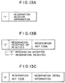
- FIG. 13A to FIG. 13C are diagrams showing various pieces of information sent and received between the reservation center and the reservation terminal in the embodiment of FIG. 9.
- Figs. 2 to 8 disclose and discuss elements which may be employed in an embodiment of the invention shown in Fig. 9.
- FIG. 2 is a block diagram showing the configuration of a multi-location conference system which comprises a conference device 1, television conference terminals 3 connected to the conference device 1 via a switching device, such as an ISDN 4, and a reservation center 5 connected to the conference device 1.
- a switching device such as an ISDN 4
- a reservation center 5 connected to the conference device 1.
- the functions of the conference device 1 and the conference terminals 3 are basically identical to those of the conference device CD and the conference terminals CT in FIG. 1.
- the switching device 4 is used in place of the ring network RN in FIG. 1, and provides a corresponding functions.
- One of the terminals 3 is designated a master terminal 3m, and other terminals are designated subordinate terminals 3s, one of which is designated a representative terminal 3sr.
- the terminals 3 are operated by the personnel of various departments of a corporation at distant geographical locations. It is convenient if they are situated at or near the offices of the respective departments, and the master terminal 3m is disposed, e.g., at or near the office of the president of the corporation.
- the reservation center 5 is manipulated by the personnel of the department of the corporation in charge of the management of the conference system, and may be disposed at or near the office of such department.
- the conference device 1 on the other hand need not be manipulated during conference or reservation of the conference, and as it requires a considerable space for installment, it may conveniently be situated at a location relatively remote from the offices, e.g., in the exchanger room of the office building.
- the conference device 1 and the reservation center 5 are assumed to be situated in the same office building or same premise, and the switching device 4 is not used for interconnecting the conference device 1 and the reservation center 5.
- the conference device 1 comprises transceivers 11 which are provided for each of the lines connected to the switching device 4.
- the transceivers 11 are connected via the switching device 4 to the conference terminals 3, and temporarily store data sent from the connected conference terminals 3.
- Digital-to-analog (D/A) converters 12 and analog-to-digital (A/D) converters 14 which are connected to the respective transceivers 11.
- the D/A converters 12 convert the conference data received and stored at the corresponding transceiver 11, into an analog signal.
- a conference data synthesizer 16 performs synthetic processing on the conference data received from the D/A converters 12.
- the synthetic processing includes selective mixing (superimposition) of audio signals and selection of video signals. That is, for each intended terminal (master terminal or a subordinate terminal) participating in a conference, the audio data sent from all the terminals participating in the same conference except the terminal in question are mixed and sent to the terminal in question.
- the video signals from the representative terminal in the same conference is selected and sent to the master terminal.
- the video signals from the master terminal is normally selected and sent to each of the subordinate terminals in the same conference. When one of the subordinate terminals is making a speech, the video signals from this subordinate terminal may be selected and sent to other subordinate terminals and to the master terminal.
- the conference data synthesizer 16 performs the synthetic processing by referring to conference terminal information stored in a conference table 17.
- the conference table 17 stores the information determining the specific manner of synthesis, i.e., selection of the video signals and selective mixing of the audio signals.
- the contents of the conference table 17 can be altered by manipulation of an input means (not shown) at the master terminal 3m. That is, the selection of the video signals and the selective mixing of the audio signals can be altered by manipulation of the input means at the master terminal 3m.
- the conference data synthesizer 16 can perform synthetic processing for a plurality of conferences concurrently.
- FIG. 3A and FIG. 3B are schematic illustrations of an example of the conference data synthesizer 16.
- FIG. 3A shows the part of the synthesizer 16 relating to the audio signals
- FIG. 3B shows the part of the synthesizer 16 relating to the video signals.
- FIG. 3A and FIG. 3B it is assumed two conferences are held simultaneously, and conference denoted by 3m-1, 3sr-1 and 3s-1 are participating in one of the conferences, and conference terminals denoted by 3m-2, 3sr-2 and 3s are participating in another conference.
- the horizontal lines are connected to the D/A converters 12 for the respective terminals 3m-1, 3sr-1, 3s-1, 3m-2, 3sr-2 and 3s-2, and the vertical lines are connected to the A/D converters for the respective terminals 3m-1, 3sr-1, 3s-1, 3m-2, 3sr-2 and 3s-2.
- the marks "x" at the intersections between horizontal and vertical lines indicate that the intersecting lines are connected with each other.
- the signal appearing on a vertical line results from mixing the signals from the horizontal lines with which the vertical line is connected.
- the signal appearing on a vertical line results from selection of the signal from the horizontal line with which the vertical line is connected.
- the A/D converters 14 convert the analog signals that have been produced from the synthesizer 16, and output the digital signals.
- the transceivers 3 receive the digital data from the respective A/D converters 14 and send them to the conference terminals to which they are connected.
- the conference data synthesizer 16 is connected to the conference table 17.
- the conference table 17 is configured as shown in FIG. 6, and stores conference information 50 on each of the conferences being held by the conference device.
- Conference information 50 for each conference consists of a conference status field 51 which indicates whether there is a conference in progress ("1") or not ("0"); a conference number field 52, consisting, for example, of a 4-bit numeral (no duplication permitted); a master terminal field 53 indicating the conference terminal 3 acting as the conference host; a representative terminal field 54 indicating one of the subordinate terminals which acts as the representative; a subordinate terminal number field 55 indicating the number of conference terminals 3 other than the conference host (master terminal); and subordinate terminal fields 56-1 to 56-M identifying the respective subordinate terminals 3s participating in the conference.
- the information identifying each subordinate terminal may consist of the telephone number.
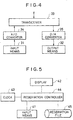
- each of the conference terminals 3 comprises a conference data input means 31, such as, for example, a microphone, video camera or the like, for inputting audio and video data, and a conference data output means 32, such as, for example, a loudspeaker, television monitor or the like, for outputting audio and video data (the synthetic conference data resulting from the synthetic processing carried out at the conference device 1.
- a conference data input means 31 such as, for example, a microphone, video camera or the like
- a conference data output means 32 such as, for example, a loudspeaker, television monitor or the like, for outputting audio and video data (the synthetic conference data resulting from the synthetic processing carried out at the conference device 1.
- the conference terminal 3 further includes a terminal transceiver 33 with the functions of receiving and temporarily storing the data from the switching device 4 and of sending the temporarily stored data, an A/D converter 34 for converting the conference data (analog signals) input from the conference data input means 31 into digital signals capable of being sent, and a D/A converter 35 for converting the synthetic conference data (digital signals) received by the terminal transceiver 33 into analog signals.
- a terminal transceiver 33 with the functions of receiving and temporarily storing the data from the switching device 4 and of sending the temporarily stored data
- an A/D converter 34 for converting the conference data (analog signals) input from the conference data input means 31 into digital signals capable of being sent
- a D/A converter 35 for converting the synthetic conference data (digital signals) received by the terminal transceiver 33 into analog signals.
- the reservation center 5 performs automatic control of starting and ending of multi-location conferences carried out by the conference device 1.
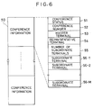
- the conference device 1 comprises an input means 41, such as, for example, a keyboard or the like, for the inputting of reserved conference information, a display means 42, such as, for example, a television monitor or the like, by which the operator is informed of the reserved conference information and of the operational status of multi-location conferences being held by the conference device 1 to which it is associated.
- a clock 43 provides information on the time, i.e., the year, month, day, hour, minute and second.
- a conference reservation control means 44 provides for new registration, modification and deletion of the reserved conference information, and indicates, when the time comes for the starting or ending of the reserved conference information, the starting or ending of the respective conferences.
- a reservation file 45 is in the form of a medium such as, for example, a hard disk, which stores the reserved conference information input as above described.
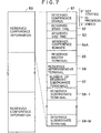
- the reservation file 45 is composed of a plurality of blocks of reserved conference information 60 as shown in FIG. 7, and each block of the reserved conference information 60 is comprised of a field for the reserved conference status 61, which is at "0" if the conference has not been started, at "1” if it is in progress and at "2" if it has ended.
- the reservation file 45 also includes a field 62 for the reserved start time indicating the time a reserved conference starts, a field 63 for the reserved end time indicating the time a reserved conference ends, a field 64A for the reserved conference number consisting, for example, of four bits (no duplication permitted), a field 65 for the reserved master terminal which acts as the host of the reserved conference, a field 66 for the reserved representative terminal 66 which is one of the reserved subordinate terminals designated to act as the representative, a field 67 indicating the number of reserved subordinate terminals, and fields 68-1 to 68-M for identifying the respective reserved subordinate terminals which participate in the reserved conference.
- the conference reservation control means 44 first reads information on the year, month, date, hour, minute and second from the clock 43, and then, at (at step ST2) reads sequentially, in the ascending order (from the head to the tail), from the reservation file 45, the reserved conference information for which the reserved conference status field 61 contains a value other than "2". Then (step ST3), the reserved start time 62 in the field for the reserved conference information 60 of which the reserved conference status field 61 contains "0" is compared with the current time information read from the clock 43 in step ST1.
- the contents of the field for the reserved conference information 60 in the reservation file 43 of the reservation center 5 are transferred (copied) to the area for the conference terminal information 50 in the conference table 17 of the conference device 1 of which the conference status field 51 contains "0" (step ST4), and the reserved conference status field 61 of that reserved conference information 60 is set to "1" (step ST5).
- the transferring operation above described consists of transferring and storing the content of the reserved conference number 64A to the field 52 for the conference number in the conference information 50, the content of the reserved master terminal 65 to the field 53 for the master terminal, the content of the reserved representative terminal 66 to the field 54 for the representative terminal, the content of the number of reserved the subordinate terminals 67 to the field 55 for the number of the subordinate terminals, and the contents of the reserved subordinate terminals 68-1 to 68-M to the fields 56-1 to 56-M for the subordinate terminals, thereby enabling the conference information synthesizer 16 to hold a plurality of conferences simultaneously in accordance with the conference table 17.
- step ST6 a comparison is made (step ST6) between, on one hand, the reserved end time 63 of the reserved conference information 60 of which the reserved conference status 61 is "1" and, on the other, the current time information read from the clock 43 in step ST1, and if the current time and the reserved end time are found to match, the corresponding conference information 50 is deleted from the conference table 17, i.e., the conference status 51 is reset to "0" (Step ST7), the reserved conference status 61 in the reserved conference information 60 described above is set to "2" (step ST8). The above operations are performed throughout the entire file (step ST9).
- the explanation was made on the assumption that the switching device 4 such as an ISDN was used as the switching means connecting the conference terminals 3 and the conference device 1 and transferring data between them. But similar results may be achieved by the use of a ring network.
- FIG. 9 An embodiment of the invention will now be described with reference to FIG. 9, in which parts that are identical with or corresponding to those of the multi-location conference system of FIG. 2 to FIG. 7 are identified with the same reference numerals, and their description is omitted.
- the reservation center 5 of this embodiment is connected via a communication line such as a telephone line 7 to reservation terminals 8.
- a communication line such as a telephone line 7
- modems 6 are inserted.
- the reservation terminals 8 are used for sending reserved conference information from remote locations to the reservation center 5.
- the reservation terminals 8 may be in the same premises or same office building as the conference terminals 3, and may be disposed adjacent to the conference terminals 3.
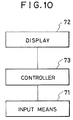
- each reservation terminal 8 comprises a reservation terminal input means 71 such as a keyboard or the like for inputting the reserved conference information 60, a reservation terminal display means 72 such as a television monitor or the like for displaying information concerning operation for registration in the reservation center 5, and a reservation terminal control means 73 for the new registration, modification or deletion of the reserved conference information 60.
- a reservation terminal input means 71 such as a keyboard or the like for inputting the reserved conference information 60
- a reservation terminal display means 72 such as a television monitor or the like for displaying information concerning operation for registration in the reservation center 5
- a reservation terminal control means 73 for the new registration, modification or deletion of the reserved conference information 60.
- FIG. 11 The configuration of the reservation file 45 at the reservation center 5 of this embodiment is shown in FIG. 11, in which parts that are identical with or corresponding to those parts in the reservation file 45 of the first embodiment of FIG. 2 to FIG. 8 are identified with the same reference numerals, and their description is omitted. As illustrated in FIG. 11, in which parts that are identical with or corresponding to those parts in the reservation file 45 of the first embodiment of FIG. 2 to FIG. 8 are identified with the same reference numerals, and their description is omitted. As illustrated in FIG.
- the reservation file 45 includes a field 64B for indicating the conference name consisting, for example, of 20 characters in "kanji (Chinese characters)" and/or alphanumeric code, a field 65a for identifying the terminal, a field 65b for identifying the participating department at the master terminal, consisting of 6 alphanumeric characters, a field 65c for identifying the person in charge at the master terminal, consisting of 10 characters in "kanji” and/or alphanumeric code, a field 65d for indicating the telephone number of the master terminal, consisting of 20 numeric characters, a field 65e for the indicating the number of participating persons at the master terminal, consisting of 2 numeric characters, and fields 68-1 to 68-M for the respective subordinate terminals.
- a field 64B for indicating the conference name consisting, for example, of 20 characters in "kanji (Chinese characters)" and/or alphanumeric code
- a field 65a for identifying the terminal
- a field 65b for identifying the participating department at
- Each of the fields 68-1 to 68-N comprises a field 68a for identifying the terminal, a filed 68b for identifying the participating department at the subordinate terminal consisting of 6 alphanumeric characters, a field 68c for identifying the person in charge at the subordinate terminal, consisting of 10 characters in "kanji" and/or alphanumeric code, a field 68d for indicating the telephone number of the subordinate terminal, consisting of 20 numeric characters, and a field 68e for indicating the number of participating persons at the subordinate terminal, consisting of 2 numeric characters.
- the operations of the system other than the registration procedure are similar to those described previously, and their description is omitted.
- the operations for the registration of this embodiment differ in that the reservation information is divided into reservation decision information and reservation detail information, and the reservation information is first sent from one of the reservation terminals 8 to the reservation center 5, a decision is made at the reservation center 5 as to whether to accept or reject the reservation, the result of the decision is sent from the reservation center 5 to the reservation terminal 8, and, if the result of the decision indicates that the reservation is accepted, the reservation detail information is then sent from the reservation terminal 8 to the reservation center 5.
- the reservation decision information comprise information in the fields 62, 63, 65a, 66, 67 and 68a in FIG. 11, and the reservation detail information comprise the information in the remaining fields in FIG. 11.
- reservation center 5 is in the standby state, ready to receive a command from the reservation terminal 8.
- the reservation terminal 8 sends information of a transmission pattern shown in FIG. 13A to the reservation center 5, for registering the reservation (203).
- the reservation center 5 makes a decision by referring to the reservation file 45 as to the status of the conference terminals 3 and the conference devices 1, and if the reservation can be accepted, a reservation number is assigned and written in the reserved conference number field 64A and a reservation key code is created (204), and information of a transmission pattern shown in FIG. 13B is then returned to the reservation terminal 8 (205).
- the reservation terminal 8 When it receives this return pattern of FIG. 13B, the reservation terminal 8 notifies the operator by display (206) appearing on the reservation terminal display means 72 as to whether the reservation request has been accepted or not, and if the reservation has been accepted, sends to the reservation center 5 the reservation detail information previously input, along with the key code received in a transmission pattern shown in FIG. 13C (207).
- the reservation detail information is received at the reservation center 5 the information is registered as the reserved conference information 60, in the reservation file 45 (208).
- this registration is completed, the communication line between reservation terminal 8 and reservation center 5 is disconnected (209).
- the time required for sending the reservation decision information is about 1 to 2 seconds, and the time require for sending the reservation detail information is on the order of 10 seconds.
- the telephone line 7 was used as a communication line connecting the reservation center 5 and the reservation terminals 8, however a similar effect can be achieved by the use of a dedicated line or private communication line.
- a plurality of reservation terminals 8 are provided. But, there may be only one reservation terminal 8.
- the reservation decision information required for the decision as to whether to accept or reject the reservation is sent first.
- a decision as to acceptance or rejection and the reservation detail information is thereafter sent from the reservation terminal to the reservation center only after the reservation is accepted.
- An advantage is that the decision can be made in shorter time, and transmission equipment, such as modems, with lower transmission speed can be used.
Description
- The present invention relates to a multi-location television conference system to which a plurality of conference terminals are connected using a switching means, so that conferences can be conducted between the conference terminals.
- The publication AT&T Technology, Vol. 1, No. 1, 1986, Short Hills, New Jersey, USA contains an article by Spilman, "Customized Digital Network for the Department of Defence", pages 58 to 65, which discloses a teleconferencing service controller for dynamic switching during the conference. A video conference controller is operated by a chairperson to set up and control the conference. In setting up the conference, a conferencing request is sent to a special service management system which accepts reservations and schedules the configuration of a network to support the conference.
- The Patent Abstracts of Japan, Vol. 14, No. 28, E-875, January 19, 1990 (JP-A-1-264 463) disclosed a conference device having a memory for registering persons to attend a conference, their telephone numbers and a main controller for actuating the conference in a reserved time only. The conference device also comprises a reservation table memory for storing identification codes of the persons participating as well as the date and time of the conference. The controller connects the persons to hold the conference and disconnects the conference by control of a telephone exchange.
- The Patent Abstracts of Japan, Vol. 14, No. 362, E-960, August 6, 1990 (JP-A-2-126762) discloses a controller for telephone conferencing including a conference device to accommodate communication between telephone terminals and one particular host telephone terminal. An interface board associated with a personal computer is provided at the host terminal to execute reservation control.
- FIG. 1 is a block diagram showing another conventional multi-location television conference system such as the one disclosed in, for example, Japanese Patent Kokai Publication JP-A-1-265767. The illustrated conference system comprises a plurality of conference terminals CT participating in multi-location television conferences, a ring network RN to which the conference terminals CT are connected, and a conference device CD connected to the ring network RN to hold the conferences.
- The television conference is held using a multiple-address, simultaneous communication channel and an individual communication channel of a time-division multiplex channel as a communication path RN of ring network configuration. That is, in a television conference terminal CT, video and audio conference data are input by means of a video camera and a microphone, and are then placed by means of a transmitter onto the individual communication channel of the ring network RN for transmission to the conference device CD.
- The conference device CD uses its receiver to receive conference data from the respective conference terminals CT via the individual communication channels of the ring network RN and synthesizes them in the conference data synthesizer. It then places the synthetic conference data through its transmitter onto the multiple-address communication channel of the ring network RN and sends it to all the conference terminals CT.
- Each of the conference terminals CT, using its receiver, receives the conference data on the multiple-address channel of the ring network RN, and outputs the data by means of an image display, such as a television monitor and a loudspeaker.
- When a switching device is used in place of the ring network RN, it is possible to effect multi-location conferences in a similar manner by connecting the conference device CD and the switching device with a plurality of lines, thereby providing one-to-one connection between each conference terminal CT and the conference device CD via the switching device.
- The conventional multi-location television conference system as described above has a number of problems. First, the applicability is limited when a ring network RN is used within a specific corporation or an establishment. Also, the system can not be applied to multi-location conferences between widely separated locations, such as between distant cities. In addition, in a conventional multi-location television conference system implemented by means of an integrated service digital network (hereinafter abbreviated "ISDN"), the number of lines subscribed to connect the conference device CD with the ISDN must not be less than the maximum number of terminals participating in the conference. When multi-location conferences are held between a small number of conference terminals CT, there will be a considerable number of lines which are subscribed but are not actually used. Thus, the ratio of utility of the lines is low. Moreover, when each conference can be held with a selected one of a plurality of line speeds, e.g., H0 (384 kbps) and 2B (2 x 64 kbps), the utility of the conference devices may be low if no particular consideration is given since each conference device cannot communicate with the conference terminals at different line speeds simultaneously. That is, each conference device CD cannot communicate with the conference terminals at different line speeds simultaneously. When it communicates with one of the line speeds (e.g., 2B), it cannot simultaneously communicate with another conference terminal CT at another line speed (e.g., H0). As a result, each conference device CD cannot holds conferences at different line speeds simultaneously. When it holds a conference at one of the line speeds, it cannot simultaneously hold another conference at another line speed. When for instance all the conference devices CD have been assigned to conferences at a certain line speed, no further conference cannot be held at a different line speed even if there are adequate vacant lines with which the conference terminals which are to participate in the contemplated conference can be connected to any of the conference device CD.
- An object of the present invention is to make it possible to automatically control starting and ending of such multi-location conferences in accordance with previously collected reserved conference information.
- Another object of the present invention is to make it possible to hold a plurality of multi-location conferences simultaneously.
- A multi-location conference system is provided in accordance with the present invention as defined in
claim 1. - A conference table manages the conference terminal information, and thus arranges for the holding of multi-location conferences in accordance with reserved conference information previously registered in a reservation center, with the result that the starting and ending of these conferences are controlled automatically, and a plurality of multi-location conferences can be held simultaneously.
- There is further provided a reservation terminal connected to the reservation center via a communication line, and the reserved conference information comprises a reservation decision information requisite for making the decision as to whether to accept or reject the reservation, and reservation detail information. The reservation terminal sends the reservation decision information via a communication line to said reservation center. The reservation center, responsive to the reservation decision information, makes a decision as to whether to accept or reject the reservation at said reservation center and sends the decision to said reservation terminal. The reservation terminal sends, if the result of the decision is to accept the reservation, the reservation detail information to said reservation center, thereby to achieve the registration of the reserved conference information in the reservation center.
- With the above configuration, the reservation detail information is sent only after the reservation is accepted. As a result, the overall amount of information that is exchanged for the reservation is reduced, allowing the use of low-speed components, e.g., a low-speed modem.
- FIG. 1 is a block diagram showing the configuration of a conventional multi-location conference system.
- FIG. 2 is a block diagram showing the configuration of a multi-location conference system applicable to the invention.
- FIG. 3 is a block diagram showing the configuration of a conference device used in the system of FIG. 2.
- FIG. 3A and FIG. 3B are diagrams showing an example of the conference data synthesizer in FIG. 3.
- FIG. 4 is a block diagram showing the configuration of an example of a conference terminal used in the system of FIG. 2.
- FIG. 5 is a block diagram showing the configuration of an example of a reservation center used in the system of FIG. 2.
- FIG. 6 is a block diagram showing the configuration of an example of a conference table used in the system of FIG. 2.
- FIG. 7 is a block diagram showing the configuration of an example of a reservation file at the reservation center used in the system of FIG. 2.
- FIG. 8 is a flow chart for explaining the operation of the system of FIG. 2.
- FIG. 9 is a block diagram showing the configuration of a multi-location conference system of an embodiment of the invention.
- FIG. 10 is a block diagram showing the configuration of an example of a reservation terminal used in the embodiment of FIG. 9.
- FIG. 11 is a block diagram showing the configuration of an example of a reservation file at the reservation center used in the embodiment of FIG. 9.
- FIG. 12 is a processing sequence for explaining the registration of the reserved conference information in the embodiment of FIG. 9.
- FIG. 13A to FIG. 13C are diagrams showing various pieces of information sent and received between the reservation center and the reservation terminal in the embodiment of FIG. 9.
- The following Figs. 2 to 8 disclose and discuss elements which may be employed in an embodiment of the invention shown in Fig. 9.
- FIG. 2 is a block diagram showing the configuration of a multi-location conference system which comprises a
conference device 1,television conference terminals 3 connected to theconference device 1 via a switching device, such as anISDN 4, and areservation center 5 connected to theconference device 1. - The functions of the
conference device 1 and theconference terminals 3 are basically identical to those of the conference device CD and the conference terminals CT in FIG. 1. Theswitching device 4 is used in place of the ring network RN in FIG. 1, and provides a corresponding functions. One of theterminals 3 is designated amaster terminal 3m, and other terminals are designatedsubordinate terminals 3s, one of which is designated a representative terminal 3sr. In the illustrated embodiment, it is assumed that theterminals 3 are operated by the personnel of various departments of a corporation at distant geographical locations. It is convenient if they are situated at or near the offices of the respective departments, and themaster terminal 3m is disposed, e.g., at or near the office of the president of the corporation. Thereservation center 5 is manipulated by the personnel of the department of the corporation in charge of the management of the conference system, and may be disposed at or near the office of such department. Theconference device 1 on the other hand need not be manipulated during conference or reservation of the conference, and as it requires a considerable space for installment, it may conveniently be situated at a location relatively remote from the offices, e.g., in the exchanger room of the office building. In the illustrated system, theconference device 1 and thereservation center 5 are assumed to be situated in the same office building or same premise, and theswitching device 4 is not used for interconnecting theconference device 1 and thereservation center 5. - The configuration of the
conference device 1 is shown in FIG. 3. As illustrated, theconference device 1 comprisestransceivers 11 which are provided for each of the lines connected to theswitching device 4. Thetransceivers 11 are connected via theswitching device 4 to theconference terminals 3, and temporarily store data sent from the connectedconference terminals 3. Digital-to-analog (D/A)converters 12 and analog-to-digital (A/D)converters 14 which are connected to therespective transceivers 11. The D/A converters 12 convert the conference data received and stored at the correspondingtransceiver 11, into an analog signal. - A
conference data synthesizer 16 performs synthetic processing on the conference data received from the D/A converters 12. The synthetic processing includes selective mixing (superimposition) of audio signals and selection of video signals. That is, for each intended terminal (master terminal or a subordinate terminal) participating in a conference, the audio data sent from all the terminals participating in the same conference except the terminal in question are mixed and sent to the terminal in question. For the master terminal in a conference, the video signals from the representative terminal in the same conference is selected and sent to the master terminal. For each of the subordinate terminals in a conference, the video signals from the master terminal is normally selected and sent to each of the subordinate terminals in the same conference. When one of the subordinate terminals is making a speech, the video signals from this subordinate terminal may be selected and sent to other subordinate terminals and to the master terminal. - The
conference data synthesizer 16 performs the synthetic processing by referring to conference terminal information stored in a conference table 17. This means that the conference table 17 stores the information determining the specific manner of synthesis, i.e., selection of the video signals and selective mixing of the audio signals. The contents of the conference table 17 can be altered by manipulation of an input means (not shown) at themaster terminal 3m. That is, the selection of the video signals and the selective mixing of the audio signals can be altered by manipulation of the input means at themaster terminal 3m. - The
conference data synthesizer 16 can perform synthetic processing for a plurality of conferences concurrently. FIG. 3A and FIG. 3B are schematic illustrations of an example of theconference data synthesizer 16. FIG. 3A shows the part of thesynthesizer 16 relating to the audio signals, and FIG. 3B shows the part of thesynthesizer 16 relating to the video signals. In FIG. 3A and FIG. 3B, it is assumed two conferences are held simultaneously, and conference denoted by 3m-1, 3sr-1 and 3s-1 are participating in one of the conferences, and conference terminals denoted by 3m-2, 3sr-2 and 3s are participating in another conference. The horizontal lines are connected to the D/A converters 12 for therespective terminals 3m-1, 3sr-1, 3s-1, 3m-2, 3sr-2 and 3s-2, and the vertical lines are connected to the A/D converters for therespective terminals 3m-1, 3sr-1, 3s-1, 3m-2, 3sr-2 and 3s-2. In FIG. 3A and FIG. 3B, the marks "x" at the intersections between horizontal and vertical lines indicate that the intersecting lines are connected with each other. In FIG. 3A, the signal appearing on a vertical line results from mixing the signals from the horizontal lines with which the vertical line is connected. In FIG. 3B, the signal appearing on a vertical line results from selection of the signal from the horizontal line with which the vertical line is connected. - The A/
D converters 14 convert the analog signals that have been produced from thesynthesizer 16, and output the digital signals. Thetransceivers 3 receive the digital data from the respective A/D converters 14 and send them to the conference terminals to which they are connected. - The
conference data synthesizer 16 is connected to the conference table 17. - The conference table 17 is configured as shown in FIG. 6, and stores
conference information 50 on each of the conferences being held by the conference device.Conference information 50 for each conference consists of aconference status field 51 which indicates whether there is a conference in progress ("1") or not ("0"); aconference number field 52, consisting, for example, of a 4-bit numeral (no duplication permitted); amaster terminal field 53 indicating theconference terminal 3 acting as the conference host; a representativeterminal field 54 indicating one of the subordinate terminals which acts as the representative; a subordinateterminal number field 55 indicating the number ofconference terminals 3 other than the conference host (master terminal); and subordinate terminal fields 56-1 to 56-M identifying the respectivesubordinate terminals 3s participating in the conference. The information identifying each subordinate terminal may consist of the telephone number. - The configuration of each of the
conference terminals 3 is shown in FIG. 4. As illustrated, it comprises a conference data input means 31, such as, for example, a microphone, video camera or the like, for inputting audio and video data, and a conference data output means 32, such as, for example, a loudspeaker, television monitor or the like, for outputting audio and video data (the synthetic conference data resulting from the synthetic processing carried out at theconference device 1. Theconference terminal 3 further includes aterminal transceiver 33 with the functions of receiving and temporarily storing the data from theswitching device 4 and of sending the temporarily stored data, an A/D converter 34 for converting the conference data (analog signals) input from the conference data input means 31 into digital signals capable of being sent, and a D/A converter 35 for converting the synthetic conference data (digital signals) received by theterminal transceiver 33 into analog signals. - The
reservation center 5 performs automatic control of starting and ending of multi-location conferences carried out by theconference device 1. As illustrated, theconference device 1 comprises an input means 41, such as, for example, a keyboard or the like, for the inputting of reserved conference information, a display means 42, such as, for example, a television monitor or the like, by which the operator is informed of the reserved conference information and of the operational status of multi-location conferences being held by theconference device 1 to which it is associated. Aclock 43 provides information on the time, i.e., the year, month, day, hour, minute and second. A conference reservation control means 44 provides for new registration, modification and deletion of the reserved conference information, and indicates, when the time comes for the starting or ending of the reserved conference information, the starting or ending of the respective conferences. Areservation file 45 is in the form of a medium such as, for example, a hard disk, which stores the reserved conference information input as above described. - The
reservation file 45 is composed of a plurality of blocks ofreserved conference information 60 as shown in FIG. 7, and each block of the reservedconference information 60 is comprised of a field for the reservedconference status 61, which is at "0" if the conference has not been started, at "1" if it is in progress and at "2" if it has ended. Thereservation file 45 also includes afield 62 for the reserved start time indicating the time a reserved conference starts, afield 63 for the reserved end time indicating the time a reserved conference ends, afield 64A for the reserved conference number consisting, for example, of four bits (no duplication permitted), afield 65 for the reserved master terminal which acts as the host of the reserved conference, afield 66 for the reserved representative terminal 66 which is one of the reserved subordinate terminals designated to act as the representative, afield 67 indicating the number of reserved subordinate terminals, and fields 68-1 to 68-M for identifying the respective reserved subordinate terminals which participate in the reserved conference. - The operation of the conference system will now be described with reference to FIG. 8. At step ST1, the conference reservation control means 44 first reads information on the year, month, date, hour, minute and second from the
clock 43, and then, at (at step ST2) reads sequentially, in the ascending order (from the head to the tail), from thereservation file 45, the reserved conference information for which the reservedconference status field 61 contains a value other than "2". Then (step ST3), thereserved start time 62 in the field for the reservedconference information 60 of which the reservedconference status field 61 contains "0" is compared with the current time information read from theclock 43 in step ST1. - When the current time and the reserved start time are found to match, the contents of the field for the reserved
conference information 60 in thereservation file 43 of thereservation center 5 are transferred (copied) to the area for theconference terminal information 50 in the conference table 17 of theconference device 1 of which theconference status field 51 contains "0" (step ST4), and the reservedconference status field 61 of that reservedconference information 60 is set to "1" (step ST5). - The transferring operation above described consists of transferring and storing the content of the reserved
conference number 64A to thefield 52 for the conference number in theconference information 50, the content of the reservedmaster terminal 65 to thefield 53 for the master terminal, the content of the reserved representative terminal 66 to thefield 54 for the representative terminal, the content of the number of reserved thesubordinate terminals 67 to thefield 55 for the number of the subordinate terminals, and the contents of the reserved subordinate terminals 68-1 to 68-M to the fields 56-1 to 56-M for the subordinate terminals, thereby enabling theconference information synthesizer 16 to hold a plurality of conferences simultaneously in accordance with the conference table 17. - Next, a comparison is made (step ST6) between, on one hand, the
reserved end time 63 of the reservedconference information 60 of which the reservedconference status 61 is "1" and, on the other, the current time information read from theclock 43 in step ST1, and if the current time and the reserved end time are found to match, the correspondingconference information 50 is deleted from the conference table 17, i.e., theconference status 51 is reset to "0" (Step ST7), the reservedconference status 61 in the reservedconference information 60 described above is set to "2" (step ST8). The above operations are performed throughout the entire file (step ST9). - In the system above described, the explanation was made on the assumption that the
switching device 4 such as an ISDN was used as the switching means connecting theconference terminals 3 and theconference device 1 and transferring data between them. But similar results may be achieved by the use of a ring network. - As has been above described, it is possible to conduct a plurality of multi-location conferences simultaneously and to effect automatic control of the starting and ending of each of the conferences, by providing in a conference device a conference table that manages conference information and execution and management of multi-location television conferences are made in accordance with reserved conference information registered in the reservation center.
- An embodiment of the invention will now be described with reference to FIG. 9, in which parts that are identical with or corresponding to those of the multi-location conference system of FIG. 2 to FIG. 7 are identified with the same reference numerals, and their description is omitted.
- As illustrated in FIG. 9, the
reservation center 5 of this embodiment is connected via a communication line such as atelephone line 7 toreservation terminals 8. For connection of thereservation center 5 with thetelephone line 7,modems 6 are inserted. Thereservation terminals 8 are used for sending reserved conference information from remote locations to thereservation center 5. Thereservation terminals 8 may be in the same premises or same office building as theconference terminals 3, and may be disposed adjacent to theconference terminals 3. - The configuration of each
reservation terminal 8 is shown in FIG. 10. As illustrated, it comprises a reservation terminal input means 71 such as a keyboard or the like for inputting the reservedconference information 60, a reservation terminal display means 72 such as a television monitor or the like for displaying information concerning operation for registration in thereservation center 5, and a reservation terminal control means 73 for the new registration, modification or deletion of the reservedconference information 60. - The configuration of the
reservation file 45 at thereservation center 5 of this embodiment is shown in FIG. 11, in which parts that are identical with or corresponding to those parts in thereservation file 45 of the first embodiment of FIG. 2 to FIG. 8 are identified with the same reference numerals, and their description is omitted. As illustrated in FIG. 11, thereservation file 45 includes afield 64B for indicating the conference name consisting, for example, of 20 characters in "kanji (Chinese characters)" and/or alphanumeric code, afield 65a for identifying the terminal, afield 65b for identifying the participating department at the master terminal, consisting of 6 alphanumeric characters, afield 65c for identifying the person in charge at the master terminal, consisting of 10 characters in "kanji" and/or alphanumeric code, afield 65d for indicating the telephone number of the master terminal, consisting of 20 numeric characters, afield 65e for the indicating the number of participating persons at the master terminal, consisting of 2 numeric characters, and fields 68-1 to 68-M for the respective subordinate terminals. - Each of the fields 68-1 to 68-N comprises a
field 68a for identifying the terminal, a filed 68b for identifying the participating department at the subordinate terminal consisting of 6 alphanumeric characters, afield 68c for identifying the person in charge at the subordinate terminal, consisting of 10 characters in "kanji" and/or alphanumeric code, afield 68d for indicating the telephone number of the subordinate terminal, consisting of 20 numeric characters, and afield 68e for indicating the number of participating persons at the subordinate terminal, consisting of 2 numeric characters. - The procedure for the registration of a reserved conference information at the reservation center, is shown in FIG. 12.
- The operations of the system other than the registration procedure are similar to those described previously, and their description is omitted. The operations for the registration of this embodiment differ in that the reservation information is divided into reservation decision information and reservation detail information, and the reservation information is first sent from one of the
reservation terminals 8 to thereservation center 5, a decision is made at thereservation center 5 as to whether to accept or reject the reservation, the result of the decision is sent from thereservation center 5 to thereservation terminal 8, and, if the result of the decision indicates that the reservation is accepted, the reservation detail information is then sent from thereservation terminal 8 to thereservation center 5. - For example, the reservation decision information comprise information in the
fields - The above-outlined operations are next described in further detail.
- Once a one-to-one connection has been established between the
reservation center 5 and one of thereservation terminals 8, via themodem 6 and the telephone line 7 (201), items ofreservation conference information 60 are input using the reservation terminal input means 71 (202). - At this time,
reservation center 5 is in the standby state, ready to receive a command from thereservation terminal 8. - Once all the items have been input to it, the
reservation terminal 8 sends information of a transmission pattern shown in FIG. 13A to thereservation center 5, for registering the reservation (203). On the basis of the reservation decision information of the transmission pattern that has been received (see FIG. 13A), thereservation center 5 makes a decision by referring to thereservation file 45 as to the status of theconference terminals 3 and theconference devices 1, and if the reservation can be accepted, a reservation number is assigned and written in the reservedconference number field 64A and a reservation key code is created (204), and information of a transmission pattern shown in FIG. 13B is then returned to the reservation terminal 8 (205). - When it receives this return pattern of FIG. 13B, the
reservation terminal 8 notifies the operator by display (206) appearing on the reservation terminal display means 72 as to whether the reservation request has been accepted or not, and if the reservation has been accepted, sends to thereservation center 5 the reservation detail information previously input, along with the key code received in a transmission pattern shown in FIG. 13C (207). When the reservation detail information is received at thereservation center 5 the information is registered as thereserved conference information 60, in the reservation file 45 (208). When this registration is completed, the communication line betweenreservation terminal 8 andreservation center 5 is disconnected (209). - As an example, the time required for sending the reservation decision information is about 1 to 2 seconds, and the time require for sending the reservation detail information is on the order of 10 seconds.
- As above described, the
telephone line 7 was used as a communication line connecting thereservation center 5 and thereservation terminals 8, however a similar effect can be achieved by the use of a dedicated line or private communication line. - In this embodiment, a plurality of
reservation terminals 8 are provided. But, there may be only onereservation terminal 8. - In accordance with this embodiment, when it is desired that the registration of the reserved conference information at the reservation center be carried out at reservation terminals connected via communication lines, the reservation decision information required for the decision as to whether to accept or reject the reservation is sent first. A decision as to acceptance or rejection and the reservation detail information is thereafter sent from the reservation terminal to the reservation center only after the reservation is accepted.
- An advantage is that the decision can be made in shorter time, and transmission equipment, such as modems, with lower transmission speed can be used.
Claims (2)
- A multi-location conference system comprising:a plurality of conference terminals (3) performing input and output of conference data consisting of video and audio signals;a conference device (1) which is connected to said plurality of conference terminals (3), said conference device (1) adapted to perform synthetic processing of conference data sent to it, thereby holding conferences between said plurality of conference terminals (3); anda conference table (17) storing information (51 - 56) for the conference terminals (3) participating in the conferences being held;characterized in that said system further comprisesa reservation center (5) adapted to register conference terminal information (51 - 56) in said conference table (17) and to delete the conference terminal information from the conference table (17) at times designated in accordance with reserved conference information (61 - 68) stored in advance in the reservation center (5) for the respective conferences, thereby automatically controlling starting and ending times of each of the conferences;at least one reservation terminal (8) connected with said reservation center (5) via a communication line (6, 7); whereinsaid reserved conference information comprises a reservation decision information (62, 63, 65a, 66, 67, 68a) requisite for making the decision as to whether to accept or reject the reservation, and reservation detail information (64A, 64B, 65b, 65c, 65d, 65e) required for control over holding the conference;said reservation terminal (8) being adapted to send the reservation decision information via said communication line (6, 7) to said reservation center (5);said reservation center (5), responsive to the reservation decision information, being adapted to decide whether to accept or reject the reservation at said reservation center (5), and to send the resultant decision from said reservation center (5) to said reservation terminal (8); andsaid reservation terminal (8), if the result of the decision is to accept the reservation, being adapted to send the reservation detail information to said reservation center (5), thereby to achieve the registration of said reserved conference information to the reservation center (5).
- The system of Claim 1, wherein said conference device (1) is capable of holding a plurality of conferences simultaneously.
Priority Applications (1)
| Application Number | Priority Date | Filing Date | Title |
|---|---|---|---|
| EP96101535A EP0719044B1 (en) | 1991-03-07 | 1992-03-06 | Multi-location television conference system |
Applications Claiming Priority (4)
| Application Number | Priority Date | Filing Date | Title |
|---|---|---|---|
| JP65255/91 | 1991-03-07 | ||
| JP6525591A JPH04280153A (en) | 1991-03-07 | 1991-03-07 | Multi-point conference device |
| JP3106503A JP2781079B2 (en) | 1991-04-12 | 1991-04-12 | Multipoint video conference equipment |
| JP106503/91 | 1991-04-12 |
Related Child Applications (2)
| Application Number | Title | Priority Date | Filing Date |
|---|---|---|---|
| EP96101535.1 Division-Into | 1992-03-06 | ||
| EP96101535A Division EP0719044B1 (en) | 1991-03-07 | 1992-03-06 | Multi-location television conference system |
Publications (3)
| Publication Number | Publication Date |
|---|---|
| EP0502547A2 EP0502547A2 (en) | 1992-09-09 |
| EP0502547A3 EP0502547A3 (en) | 1993-05-26 |
| EP0502547B1 true EP0502547B1 (en) | 1997-09-17 |
Family
ID=26406378
Family Applications (2)
| Application Number | Title | Priority Date | Filing Date |
|---|---|---|---|
| EP92103896A Expired - Lifetime EP0502547B1 (en) | 1991-03-07 | 1992-03-06 | Multi-location television conference system |
| EP96101535A Expired - Lifetime EP0719044B1 (en) | 1991-03-07 | 1992-03-06 | Multi-location television conference system |
Family Applications After (1)
| Application Number | Title | Priority Date | Filing Date |
|---|---|---|---|
| EP96101535A Expired - Lifetime EP0719044B1 (en) | 1991-03-07 | 1992-03-06 | Multi-location television conference system |
Country Status (3)
| Country | Link |
|---|---|
| US (1) | US5323445A (en) |
| EP (2) | EP0502547B1 (en) |
| DE (2) | DE69222204T2 (en) |
Families Citing this family (51)
| Publication number | Priority date | Publication date | Assignee | Title |
|---|---|---|---|---|
| US5821984A (en) * | 1992-09-09 | 1998-10-13 | Canon Kabushiki Kaisha | Communication conference system with storage of conference information including proceedings data |
| DE69324873T2 (en) * | 1992-09-21 | 1999-10-21 | Canon Kk | Network system and terminal device |
| US5422883A (en) * | 1992-10-16 | 1995-06-06 | International Business Machines Corporation | Call setup and channel allocation for a multi-media network bus |
| US5852466A (en) * | 1992-12-28 | 1998-12-22 | Canon Kabushiki Kaisha | Teleconference system |
| US5495284A (en) * | 1993-03-12 | 1996-02-27 | Katz; Ronald A. | Scheduling and processing system for telephone video communication |
| US20030185356A1 (en) | 1993-03-12 | 2003-10-02 | Telebuyer, Llc | Commercial product telephonic routing system with mobile wireless and video vending capability |
| US6323894B1 (en) | 1993-03-12 | 2001-11-27 | Telebuyer, Llc | Commercial product routing system with video vending capability |
| US5689553A (en) * | 1993-04-22 | 1997-11-18 | At&T Corp. | Multimedia telecommunications network and service |
| US6738357B1 (en) | 1993-06-09 | 2004-05-18 | Btg International Inc. | Method and apparatus for multiple media digital communication system |
| US5530472A (en) * | 1993-06-29 | 1996-06-25 | Sprint Communications Company L.P. | Video conference system including a non-reserved video conference capability |
| JPH0795418A (en) * | 1993-09-20 | 1995-04-07 | Canon Inc | Picture communication equipment |
| JPH0795552A (en) * | 1993-09-20 | 1995-04-07 | Fujitsu Ltd | Video conference network managing system |
| US6594688B2 (en) * | 1993-10-01 | 2003-07-15 | Collaboration Properties, Inc. | Dedicated echo canceler for a workstation |
| US5452299A (en) * | 1993-10-14 | 1995-09-19 | Intel Corporation | Optimized transfer of large object data blocks in a teleconferencing system |
| US5959978A (en) * | 1994-04-21 | 1999-09-28 | Canon Kabushiki Kaisha | Method, terminal, and system for multi-station video communication |
| US5625407A (en) * | 1994-07-08 | 1997-04-29 | Lucent Technologies Inc. | Seamless multimedia conferencing system using an enhanced multipoint control unit and enhanced endpoint devices |
| US5555017A (en) * | 1994-07-08 | 1996-09-10 | Lucent Technologies Inc. | Seamless multimedia conferencing system using an enhanced multipoint control unit |
| CA2150060C (en) * | 1994-07-08 | 2000-01-11 | John T. Biggs | Seamless multimedia conferencing system using enhanced endpoint devices |
| JP3128680B2 (en) * | 1994-07-20 | 2001-01-29 | 富士通株式会社 | Multipoint video conference system |
| JPH0879391A (en) * | 1994-09-02 | 1996-03-22 | Fujitsu Ltd | Electronic conference system |
| US5802281A (en) | 1994-09-07 | 1998-09-01 | Rsi Systems, Inc. | Peripheral audio/video communication system that interfaces with a host computer and determines format of coded audio/video signals |
| WO1996016497A1 (en) * | 1994-11-21 | 1996-05-30 | Oracle Corporation | Transferring binary large objects (blobs) in a network environment |
| US5483588A (en) * | 1994-12-23 | 1996-01-09 | Latitute Communications | Voice processing interface for a teleconference system |
| US5854898A (en) * | 1995-02-24 | 1998-12-29 | Apple Computer, Inc. | System for automatically adding additional data stream to existing media connection between two end points upon exchange of notifying and confirmation messages therebetween |
| CA2173304C (en) * | 1995-04-21 | 2003-04-29 | Anthony J. Dezonno | Method and system for establishing voice communications using a computer network |
| US5796424A (en) * | 1995-05-01 | 1998-08-18 | Bell Communications Research, Inc. | System and method for providing videoconferencing services |
| US5828743A (en) * | 1995-05-12 | 1998-10-27 | Protel, Inc. | Apparatus and method for automated audio teleconferencing having enhanced access and security features |
| WO1996036157A1 (en) * | 1995-05-12 | 1996-11-14 | Protel, Inc. | Automated audio teleconferencing having reconfiguration features |
| US5719928A (en) * | 1995-05-12 | 1998-02-17 | Protel, Inc. | Apparatus and method for automated audio teleconferencing having enhanced billing and reservation features |
| US5793415A (en) * | 1995-05-15 | 1998-08-11 | Imagetel International Inc. | Videoconferencing and multimedia system |
| US5619555A (en) * | 1995-07-28 | 1997-04-08 | Latitude Communications | Graphical computer interface for an audio conferencing system |
| US5559875A (en) * | 1995-07-31 | 1996-09-24 | Latitude Communications | Method and apparatus for recording and retrieval of audio conferences |
| US6396510B1 (en) * | 1996-06-21 | 2002-05-28 | Intel Corporation | Method and apparatus for scheduling a multi-point electronic conference |
| CA2284797C (en) * | 1997-03-31 | 2004-12-28 | Broadband Associates | Method and system for providing a presentation on a network |
| US7412533B1 (en) | 1997-03-31 | 2008-08-12 | West Corporation | Providing a presentation on a network having a plurality of synchronized media types |
| US7490169B1 (en) | 1997-03-31 | 2009-02-10 | West Corporation | Providing a presentation on a network having a plurality of synchronized media types |
| US6272214B1 (en) | 1997-11-24 | 2001-08-07 | Telefonaktiebolaget Lm Ericsson (Publ) | Automatic control of participation in telemeetings |
| US6330022B1 (en) | 1998-11-05 | 2001-12-11 | Lucent Technologies Inc. | Digital processing apparatus and method to support video conferencing in variable contexts |
| JP3415463B2 (en) * | 1999-01-19 | 2003-06-09 | 日本電気株式会社 | Conference communication device |
| US6774926B1 (en) * | 1999-09-03 | 2004-08-10 | United Video Properties, Inc. | Personal television channel system |
| JP3379489B2 (en) * | 1999-09-14 | 2003-02-24 | 日本電気株式会社 | Server / client type system and data download method |
| JP2002359690A (en) * | 2001-03-27 | 2002-12-13 | Toshiba Corp | Telephone exchanging apparatus and telephone system |
| WO2002091128A2 (en) * | 2001-05-09 | 2002-11-14 | American Express Travel Related Services Company, Inc. | System and method for seminar reservations |
| US7022104B2 (en) * | 2003-12-08 | 2006-04-04 | Angioscore, Inc. | Facilitated balloon catheter exchange |
| NO319437B1 (en) | 2004-01-16 | 2005-08-15 | Tandberg Telecom As | Procedure for ad hoc buffer |
| WO2006051584A1 (en) * | 2004-11-10 | 2006-05-18 | Fujitsu Limited | Contents server, and contents service system |
| US8171104B2 (en) * | 2005-12-15 | 2012-05-01 | International Business Machines Corporation | Scheduling and searching meetings in a network environment |
| US8433753B2 (en) * | 2005-12-15 | 2013-04-30 | International Business Machines Corporation | Providing meeting information from a meeting server to an email server to store in an email database |
| JP2008085677A (en) * | 2006-09-27 | 2008-04-10 | Toshiba Corp | Information control device, information synthesizer and program |
| JP6019707B2 (en) | 2012-04-25 | 2016-11-02 | 株式会社リコー | Transmission management system, transmission system, and program for transmission management system |
| CN114070826A (en) * | 2021-11-05 | 2022-02-18 | 广州朗国电子科技股份有限公司 | Hongmen-based distributed data management method, system, control terminal and medium |
Family Cites Families (13)
| Publication number | Priority date | Publication date | Assignee | Title |
|---|---|---|---|---|
| JPS63240253A (en) * | 1987-03-27 | 1988-10-05 | Fujitsu Ltd | Simplified system for reservation registration |
| JPH01147946A (en) * | 1987-12-03 | 1989-06-09 | Fujitsu Ltd | Video conference system inter multi-point |
| JPH01258575A (en) * | 1988-04-08 | 1989-10-16 | Nec Corp | Method and device for switching different speed and controlling connection |
| JPH01264463A (en) * | 1988-04-15 | 1989-10-20 | Nec Corp | System for sharing preset type conference telephone system |
| JPH01265767A (en) * | 1988-04-18 | 1989-10-23 | Nippon Telegr & Teleph Corp <Ntt> | Conference communication system |
| JPH02126762A (en) * | 1988-11-04 | 1990-05-15 | Nippon Telegr & Teleph Corp <Ntt> | Controller for telephone conference |
| JPH0364157A (en) * | 1989-07-31 | 1991-03-19 | Nippon Telegr & Teleph Corp <Ntt> | Telephone conference reservation equipment |
| JPH03145363A (en) * | 1989-10-31 | 1991-06-20 | Nec Corp | Reservation information collection processing system in telephone conference system |
| JP2663659B2 (en) * | 1990-01-22 | 1997-10-15 | 日本電気株式会社 | Multipoint video conference communication system |
| US5065393A (en) * | 1990-04-10 | 1991-11-12 | Dsc Communications Corporation | Network controller billing system and method of operation |
| US5138614A (en) * | 1990-04-12 | 1992-08-11 | At&T Bell Laboratories | Transformation method for network conference connections |
| US5195086A (en) * | 1990-04-12 | 1993-03-16 | At&T Bell Laboratories | Multiple call control method in a multimedia conferencing system |
| US5136581A (en) * | 1990-07-02 | 1992-08-04 | At&T Bell Laboratories | Arrangement for reserving and allocating a plurality of competing demands for an ordered bus communication network |
-
1992
- 1992-03-05 US US07/846,146 patent/US5323445A/en not_active Expired - Fee Related
- 1992-03-06 DE DE69222204T patent/DE69222204T2/en not_active Expired - Fee Related
- 1992-03-06 EP EP92103896A patent/EP0502547B1/en not_active Expired - Lifetime
- 1992-03-06 DE DE69229682T patent/DE69229682T2/en not_active Expired - Fee Related
- 1992-03-06 EP EP96101535A patent/EP0719044B1/en not_active Expired - Lifetime
Also Published As
| Publication number | Publication date |
|---|---|
| EP0719044A2 (en) | 1996-06-26 |
| DE69222204D1 (en) | 1997-10-23 |
| DE69222204T2 (en) | 1998-04-16 |
| DE69229682T2 (en) | 2000-02-17 |
| US5323445A (en) | 1994-06-21 |
| EP0502547A3 (en) | 1993-05-26 |
| EP0719044A3 (en) | 1996-07-17 |
| EP0502547A2 (en) | 1992-09-09 |
| DE69229682D1 (en) | 1999-09-02 |
| EP0719044B1 (en) | 1999-07-28 |
Similar Documents
| Publication | Publication Date | Title |
|---|---|---|
| EP0502547B1 (en) | Multi-location television conference system | |
| US5953050A (en) | Multi-location video conferencing system | |
| EP0716533A2 (en) | A gateway system and method | |
| US6404811B1 (en) | Interactive multimedia system | |
| EP0686335B1 (en) | Communication system | |
| US5099510A (en) | Teleconferencing with bridge partitioning and other features | |
| CA2159644C (en) | System for communicating with an adsi-compatible telephone via a service circuit node | |
| KR890000220B1 (en) | Electronic conference system | |
| CN1129505A (en) | Option bus adapter for use with a digital telephone | |
| JPH05347674A (en) | Synchronization displaty controller | |
| US5821984A (en) | Communication conference system with storage of conference information including proceedings data | |
| EP0351757A2 (en) | Method of video conference, video conference terminal, method of informing and data terminal | |
| Armbruster | Applications of Future Braod-Band Services in the Office and Home | |
| US6205089B1 (en) | Communication terminal apparatus and communication conference system | |
| Pferd et al. | Special Feature: Interactive Graphics Teleconferencing | |
| WO1996037068A1 (en) | Data conferencing between remotely located participants | |
| JP4516227B2 (en) | Communications system | |
| JPS63279692A (en) | Automatic incoming distribution managing device | |
| US5663953A (en) | Multipoint intercommunication with pre-querying of members as to participation | |
| JPH04280153A (en) | Multi-point conference device | |
| JP2781079B2 (en) | Multipoint video conference equipment | |
| JP3586390B2 (en) | Video conference system | |
| JPH01264463A (en) | System for sharing preset type conference telephone system | |
| JP3609593B2 (en) | Contract work support system, contract work support method | |
| JPH02142238A (en) | Inter-multispot communication conference control system |
Legal Events
| Date | Code | Title | Description |
|---|---|---|---|
| PUAI | Public reference made under article 153(3) epc to a published international application that has entered the european phase |
Free format text: ORIGINAL CODE: 0009012 |
|
| AK | Designated contracting states |
Kind code of ref document: A2 Designated state(s): DE FR GB |
|
| PUAL | Search report despatched |
Free format text: ORIGINAL CODE: 0009013 |
|
| AK | Designated contracting states |
Kind code of ref document: A3 Designated state(s): DE FR GB |
|
| 17P | Request for examination filed |
Effective date: 19930929 |
|
| 17Q | First examination report despatched |
Effective date: 19950809 |
|
| GRAG | Despatch of communication of intention to grant |
Free format text: ORIGINAL CODE: EPIDOS AGRA |
|
| GRAH | Despatch of communication of intention to grant a patent |
Free format text: ORIGINAL CODE: EPIDOS IGRA |
|
| GRAH | Despatch of communication of intention to grant a patent |
Free format text: ORIGINAL CODE: EPIDOS IGRA |
|
| GRAA | (expected) grant |
Free format text: ORIGINAL CODE: 0009210 |
|
| DX | Miscellaneous (deleted) | ||
| AK | Designated contracting states |
Kind code of ref document: B1 Designated state(s): DE FR GB |
|
| REF | Corresponds to: |
Ref document number: 69222204 Country of ref document: DE Date of ref document: 19971023 |
|
| ET | Fr: translation filed | ||
| PLBE | No opposition filed within time limit |
Free format text: ORIGINAL CODE: 0009261 |
|
| STAA | Information on the status of an ep patent application or granted ep patent |
Free format text: STATUS: NO OPPOSITION FILED WITHIN TIME LIMIT |
|
| 26N | No opposition filed | ||
| REG | Reference to a national code |
Ref country code: GB Ref legal event code: IF02 |
|
| PGFP | Annual fee paid to national office [announced via postgrant information from national office to epo] |
Ref country code: GB Payment date: 20020306 Year of fee payment: 11 |
|
| PGFP | Annual fee paid to national office [announced via postgrant information from national office to epo] |
Ref country code: FR Payment date: 20020312 Year of fee payment: 11 |
|
| PGFP | Annual fee paid to national office [announced via postgrant information from national office to epo] |
Ref country code: DE Payment date: 20020320 Year of fee payment: 11 |
|
| PG25 | Lapsed in a contracting state [announced via postgrant information from national office to epo] |
Ref country code: GB Free format text: LAPSE BECAUSE OF NON-PAYMENT OF DUE FEES Effective date: 20030306 |
|
| PG25 | Lapsed in a contracting state [announced via postgrant information from national office to epo] |
Ref country code: DE Free format text: LAPSE BECAUSE OF NON-PAYMENT OF DUE FEES Effective date: 20031001 |
|
| GBPC | Gb: european patent ceased through non-payment of renewal fee |
Effective date: 20030306 |
|
| PG25 | Lapsed in a contracting state [announced via postgrant information from national office to epo] |
Ref country code: FR Free format text: LAPSE BECAUSE OF NON-PAYMENT OF DUE FEES Effective date: 20031127 |
|
| REG | Reference to a national code |
Ref country code: FR Ref legal event code: ST |