EP0502265A2 - Integrated process for producing iso-butene and alkyl tert-butyl ethers - Google Patents
Integrated process for producing iso-butene and alkyl tert-butyl ethers Download PDFInfo
- Publication number
- EP0502265A2 EP0502265A2 EP91202870A EP91202870A EP0502265A2 EP 0502265 A2 EP0502265 A2 EP 0502265A2 EP 91202870 A EP91202870 A EP 91202870A EP 91202870 A EP91202870 A EP 91202870A EP 0502265 A2 EP0502265 A2 EP 0502265A2
- Authority
- EP
- European Patent Office
- Prior art keywords
- stage
- column
- reactor
- iso
- hydrocarbons
- Prior art date
- Legal status (The legal status is an assumption and is not a legal conclusion. Google has not performed a legal analysis and makes no representation as to the accuracy of the status listed.)
- Granted
Links
Images


Classifications
-
- C—CHEMISTRY; METALLURGY
- C07—ORGANIC CHEMISTRY
- C07C—ACYCLIC OR CARBOCYCLIC COMPOUNDS
- C07C41/00—Preparation of ethers; Preparation of compounds having groups, groups or groups
- C07C41/01—Preparation of ethers
- C07C41/05—Preparation of ethers by addition of compounds to unsaturated compounds
- C07C41/06—Preparation of ethers by addition of compounds to unsaturated compounds by addition of organic compounds only
-
- C—CHEMISTRY; METALLURGY
- C07—ORGANIC CHEMISTRY
- C07C—ACYCLIC OR CARBOCYCLIC COMPOUNDS
- C07C5/00—Preparation of hydrocarbons from hydrocarbons containing the same number of carbon atoms
- C07C5/32—Preparation of hydrocarbons from hydrocarbons containing the same number of carbon atoms by dehydrogenation with formation of free hydrogen
- C07C5/327—Formation of non-aromatic carbon-to-carbon double bonds only
-
- C—CHEMISTRY; METALLURGY
- C07—ORGANIC CHEMISTRY
- C07C—ACYCLIC OR CARBOCYCLIC COMPOUNDS
- C07C7/00—Purification; Separation; Use of additives
- C07C7/005—Processes comprising at least two steps in series
-
- Y—GENERAL TAGGING OF NEW TECHNOLOGICAL DEVELOPMENTS; GENERAL TAGGING OF CROSS-SECTIONAL TECHNOLOGIES SPANNING OVER SEVERAL SECTIONS OF THE IPC; TECHNICAL SUBJECTS COVERED BY FORMER USPC CROSS-REFERENCE ART COLLECTIONS [XRACs] AND DIGESTS
- Y02—TECHNOLOGIES OR APPLICATIONS FOR MITIGATION OR ADAPTATION AGAINST CLIMATE CHANGE
- Y02P—CLIMATE CHANGE MITIGATION TECHNOLOGIES IN THE PRODUCTION OR PROCESSING OF GOODS
- Y02P20/00—Technologies relating to chemical industry
- Y02P20/10—Process efficiency
Definitions
- This invention relates to an integrated process for producing iso-butene and alkyl tert-butyl ethers such as methyl tert-butyl ether (MTBE), ethyl tert-butyl ether (ETBE), etc.
- MTBE methyl tert-butyl ether
- ETBE ethyl tert-butyl ether
- Alkyl tert-butyl ethers are used as high-octane additives for gasolines, and are produced by reacting iso-butene with the corresponding alcohol (methanol for MTBE, ethanol for ETBE, etc.) in the liquid phase over a suitable catalyst at a pressure of 15-40 atmospheres and a temperature of 60-100°C (see patent IT-1012690).
- the raw material is usually a mixture of field butanes, a typical block diagram of an MTBE plant therefore being as shown in Figure 1.
- the feedstock 1 comprising normal and iso-butane is fed into the distillation column 2, from which essentially iso-butane 3 leaves at the top and a stream 4 containing n-C4 and higher hydrocarbons is withdrawn from the bottom. A part 5 of the bottom stream is isomerized in the reactor 6 and recycled through 7 to the column 2.
- the iso-butane 3 is dehydrogenated in the plant 8, which provides a light gas stream 9 and a stream 10 containing iso-butane and iso-butene, which is fed to MTBE synthesis 11, in which it reacts with methanol 12 to produce MTBE 13.
- the plant 11 In addition to the MTBE, the plant 11 also provides a stream 14 containing iso-butane, which is recycled to a point upstream of the dehydrogenation reactor 8.
- the iso-butane dehydrogenation unit a scheme of which is shown in Figure 2, is based on a process similar to those currently used commercially, ie gas preparation, compression and purification.
- the iso-butane 21 is fed to the dehydrogenation reactor 22, which is followed by a compression stage 23 and a purification stage 24.
- the purification comprises separation of hydrogen, nitrogen and light hydrocarbons 25 from the C4 hydrocarbon component of the reaction product 26.
- cryogenic methods In current plants this recovery is achieved by cryogenic methods. It can also be achieved by absorption in a suitable solvent followed by C4 stripping and solvent regeneration.
- the solvent is a mixture of C6-C10 hydrocarbons.
- Figure 3 shows a typical scheme of the Snamprogetti-Yarsintez iso-butane dehydrogenation process with recovery by cryogenic methods (see Octane Week, October 8 1990, pages 7-8).
- the iso-butane 31 is preheated in the heat exchangers 32 and 33 before being fed to the dehydrogenation reactor 34, which is connected to the dehydrogenation catalyst regenerator 35 by the lines 36 and 37.
- a gaseous stream 38 leaves the top of the reactor 34 and is fed to the separator 39 after being cooled in 33, filtered in 40, compressed in 41 and partially condensed in 42.
- Two streams are obtained from the separator 39, one 43 containing mainly C4 hydrocarbons and the other 44 containing mainly hydrogen and C3 hydrocarbons.
- the stream 43 is fed to the depropanizer 45, from the bottom of which a stream 46 consisting essentially of iso-C4 is withdrawn.
- the stream 44 is fed to a low temperature recovery system 47 to recover the iso-butene and iso-butane 48 contained in it, to be added to the stream 43.
- the stream 49 leaving 47 and containing essentially hydrogen and C1-C3 hydrocarbons is combined with the stream 50 leaving the top of the depropanizer 45.
- Air 51 is fed to the regeneration column 39 after being compressed in 52 and heated in 53.
- a gaseous stream 54 leaves the top of the column 39 and is cooled in 53 and filtered through 55 before being used as fuel gas 56.
- Figure 4 shows a typical scheme of the iso-butane dehydrogenation process with recovery by absorption and stripping.
- the stream 38 leaving the reactor 34 is cooled in 33, compressed in 41 and partly condensed in the condenser 42 before being fed to the separator 39 to separate heavy hydrocarbons 43 from light hydrocarbons 44, these latter being fed to the absorber 60.
- the light gases and hydrocarbons 61 leave the top of said absorber, whereas the remainder is absorbed by the solvent fed through the line 62 and is withdrawn from the bottom 63.
- the stream 63 containing the spent solvent and the C4 hydrocarbons is fed to a distillation column 64, from the bottom 65 of which the regenerated solvent is obtained and from the top of which a stream is obtained containing essentially C4 hydrocarbons 66, this being fed to the depropanizer column 67 after being added to the stream 43.
- a stream consisting essentially of iso-C4 is withdrawn from the bottom 68 of the column 67, and a stream containing essentially C3 hydrocarbons leaves from the top 69.
- cryogenic system suffers from high investment and operating costs because of a refrigeration cycle operating at very low temperature and the costly machinery involved (such as turboexpanders).
- the main advantage of the use of these solvents is that the compounds are present as reagents (methanol, ethanol, etc.) or as products (MTBE, ETBE etc.) and that the streams containing the recovered C4s and solvent can be fed directly to process units already provided in the alkyl tert-butyl ether production plant without undergoing further treatment.
- reagents methanol, ethanol, etc.
- MTBE, ETBE etc. the streams containing the recovered C4s and solvent can be fed directly to process units already provided in the alkyl tert-butyl ether production plant without undergoing further treatment.
- the integrated process for producing iso-butene and alkyl tert-butyl ether according to the present invention comprises essentially the following stages:
- the liquid mixture containing essentially C4 hydrocarbons and the alkyl tert-butyl ether as spent solvent leaving the bottom of the absorption column of stage b) can be fed partly or totally to one or more of the following equipment items:
- the liquid mixture leaving the column is fed to the reactor of stage d).
- the alcohol separated in the distillation column downstream of the wash column of stage g) can be recycled to the reactor of stage d), and/or to the reactor of stage f) if two or more reactors are used, and/or to the absorption column of stage b).
- the unreacted C4 hydrocarbons separated in the wash column of stage g) can be conveniently mixed with the stream containing iso-butane of stage a) to be dehydrogenated together.
- the aforedescribed process can also be conducted using a column reactor in which the reactor and distillation column are combined into one and the same equipment item. In this case, part of the liquid containing essentially alkyl tert-butyl ether directly leaving the column reactor is recycled to the absorption column of stage b).
- the quantity of solvent used in the absorption column of stage b) preferably lies within the following ranges:
- That part of the liquid containing it to be fed to the absorption column is preferably between 15 and 50% by volume, and more preferably between 30 and 45%, of the total liquid leaving the distillation column of stage e).
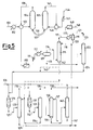
- Figure 5 shows an integrated process scheme for producing MTBE, using MTBE as absorbent.
- the feedstock 101 containing normal and iso-butanes is preheated in the heat exchangers 102 and 103 before being fed into the dehydrogenation reactor 104 which is connected to the dehydrogenation catalyst regenerator 105 by the lines 106 and 107.
- a gaseous stream 108 leaves the top of the reactor 104 and is fed to the separator 109 after being cooled in 103, filtered through 110, compressed in 111 and partly condensed in 112, to separate the heavy hydrocarbons 113 from the lighter hydrocarbons 114 which are fed to the absorber 115 in which MTBE 116 is used as solvent.
- the light gases 117 leaving the top of the absorber 115 are cooled in 118 and separated in 119 to separate from the gases 121 the MTBE 120, which is recycled to the absorber.
- the liquid stream 113 is fed to a distillation column 122 to obtain C3 hydrocarbons from the top 123 and iso-butene and iso-butane from the bottom 124.
- the iso-C4s 124 are fed to a first reactor 125 together with methanol 126 to obtain a stream containing MTBE 127, which is fed to a distillation column 128 to obtain the desired MTBE 129 from the bottom and the unreacted gases (methanol, iso-butene and iso-butane) 130 from the top.
- the gaseous stream 130 is fed into a second reactor 131 together with methanol to obtain a further stream containing MTBE 132 (with a lesser MTBE content than the stream 127), which is fed into a distillation column 133, from the bottom of which a stream 134 is obtained containing essentially MTBE which is recycled to the column 128, and from the top of which a stream 135 is obtained containing methanol, iso-butane and iso-butene, which is fed to a wash column 136 into which water 137 is fed.
- MTBE 132 with a lesser MTBE content than the stream 127
- Iso-butane 138 leaves the top of the column 136 to be recycled by being added to the stream 101, and methanol and water 139 leave the bottom to be separated in the column 140.
- a part of the stream 129 containing essentially MTBE is recycled 141 as solvent to the absorption column 115.
- the liquid stream 142 containing the C4 hydrocarbons and MTBE is fed to the distillation column 128. Part or all of it could however be fed via 143 to the reactor 125.
- Air 144 is fed to the regeneration column 105 after being compressed in 145 and heated in 146.
- a gaseous stream 147 leaves the top of the column 105 and is cooled in 146 and filtered in 148 before being used as fuel gas 149.
- Figure 6 shows a possible integrated process scheme for producing MTBE using MTBE as absorbent, as in the scheme of Figure 5, but with the difference that the bottom stream from the absorber 142 is fed together with the liquid 113 from the separator 109 to the distillation column 122.
- Figure 7 shows a possible integrated process scheme for producing MTBE using methanol as absorbent.
- the difference between this and the scheme of Figure 5 is that part of the methanol is fed to the absorption column 115 instead of part of the MTBE, the reference numerals having the same meaning as in Figure 5.
- the reactor effluent consists of:
- the reactor effluent is compressed to 20 atmospheres and cooled to 40°C to separate into a liquid stream and a gaseous stream.
- the liquid stream is formed essentially of C3, C4 and higher hydrocarbons.
- the gaseous stream still contains about 25% of C4 hydrocarbons and has the following composition:
- This stream is fed to the bottom of an absorption column, to the top of which liquid MTBE is fed at 35°C in such a quantity that the molar ratio of MTBE to feed C4 hydrocarbons is 1:1.
- the column temperature is maintained between 35 and 60°C.
- the bottom liquid stream has the following composition:
- This stream is mixed with the liquid stream from the condensation at 40°C, to give the following stream:
- This mixture is fed to a distillation column from which a residue is recovered containing the MTBE, the C4 hydrocarbons and a small quantity of propane and propylene.
- This residue is mixed with methanol in a quantity such that the methanol/iso-butene ratio is 1:1, and fed at an LHSV of 5 into the primary reactor for MTBE synthesis, where it reacts on Amberlyst 15 resin at a temperature of 60°C and a pressure of 15 atg.
- This stream is fed to the fractionation column to obtain MTBE at 98% purity from the bottom and from the top a liquid distillate which is fed to the second reactor after methanol has been added to the extent that the methanol/iso-butene molar ratio is 1.3:1.
- methanol is used as solvent, in a ratio of 1.5:1 to the C4 hydrocarbons.
- the liquid stream leaving the bottom of the absorber has the following composition:
- This stream is mixed with the residue of the light hydrocarbon separation fractionation column fed with the liquid stream condensed at 40°C after compression, and after being degassed and mixed with methanol to a methanol/iso-butene molar ratio of 1:1 is fed to the first MTBE synthesis reactor operating under the conditions of Example 1.
Abstract
Description
- This invention relates to an integrated process for producing iso-butene and alkyl tert-butyl ethers such as methyl tert-butyl ether (MTBE), ethyl tert-butyl ether (ETBE), etc.
- Alkyl tert-butyl ethers are used as high-octane additives for gasolines, and are produced by reacting iso-butene with the corresponding alcohol (methanol for MTBE, ethanol for ETBE, etc.) in the liquid phase over a suitable catalyst at a pressure of 15-40 atmospheres and a temperature of 60-100°C (see patent IT-1012690).
- The current tendency to introduce increasingly higher quantities particularly of MTBE into gasoline technology and the almost complete utilization of refinery streams containing iso-butene has led to the development of complexes for iso-butene production via dehydrogenation of iso-butane.
- The raw material is usually a mixture of field butanes, a typical block diagram of an MTBE plant therefore being as shown in Figure 1.
- The
feedstock 1 comprising normal and iso-butane is fed into thedistillation column 2, from which essentially iso-butane 3 leaves at the top and astream 4 containing n-C₄ and higher hydrocarbons is withdrawn from the bottom. Apart 5 of the bottom stream is isomerized in thereactor 6 and recycled through 7 to thecolumn 2. - The iso-
butane 3 is dehydrogenated in theplant 8, which provides a light gas stream 9 and astream 10 containing iso-butane and iso-butene, which is fed toMTBE synthesis 11, in which it reacts withmethanol 12 to produceMTBE 13. - In addition to the MTBE, the
plant 11 also provides astream 14 containing iso-butane, which is recycled to a point upstream of thedehydrogenation reactor 8. - It should be noted that the origin of dehydrogenation techniques was unrelated to MTBE production.
- However, it is predicted that most new MTBE plants will use iso-butene produced by dehydrogenation of iso-butane and likewise most iso-butane dehydrogenation plants will supply iso-butene to MTBE plants.
- Any integration of these two plants which results in savings in investment and/or operating costs is therefore of considerable interest.
- The iso-butane dehydrogenation unit, a scheme of which is shown in Figure 2, is based on a process similar to those currently used commercially, ie gas preparation, compression and purification.
- More specifically, the iso-
butane 21 is fed to thedehydrogenation reactor 22, which is followed by acompression stage 23 and apurification stage 24. - The purification comprises separation of hydrogen, nitrogen and
light hydrocarbons 25 from the C₄ hydrocarbon component of thereaction product 26. - One of the most problematic points is the recovery of C₄ hydrocarbons from the light gas stream which have remained uncondensed after compression.
- In current plants this recovery is achieved by cryogenic methods. It can also be achieved by absorption in a suitable solvent followed by C₄ stripping and solvent regeneration.
- For example, in iso-butane dehydrogenation plants the solvent is a mixture of C₆-C₁₀ hydrocarbons.
- Figure 3 shows a typical scheme of the Snamprogetti-Yarsintez iso-butane dehydrogenation process with recovery by cryogenic methods (see Octane Week, October 8 1990, pages 7-8).
- The iso-
butane 31 is preheated in theheat exchangers dehydrogenation reactor 34, which is connected to thedehydrogenation catalyst regenerator 35 by thelines - A
gaseous stream 38 leaves the top of thereactor 34 and is fed to theseparator 39 after being cooled in 33, filtered in 40, compressed in 41 and partially condensed in 42. - Two streams are obtained from the
separator 39, one 43 containing mainly C₄ hydrocarbons and the other 44 containing mainly hydrogen and C₃ hydrocarbons. - The
stream 43 is fed to thedepropanizer 45, from the bottom of which a stream 46 consisting essentially of iso-C₄ is withdrawn. Thestream 44 is fed to a lowtemperature recovery system 47 to recover the iso-butene and iso-butane 48 contained in it, to be added to thestream 43. Thestream 49 leaving 47 and containing essentially hydrogen and C₁-C₃ hydrocarbons is combined with thestream 50 leaving the top of thedepropanizer 45. -
Air 51 is fed to theregeneration column 39 after being compressed in 52 and heated in 53. - A
gaseous stream 54 leaves the top of thecolumn 39 and is cooled in 53 and filtered through 55 before being used asfuel gas 56. - Figure 4 shows a typical scheme of the iso-butane dehydrogenation process with recovery by absorption and stripping.
- Only the part relating to the purification will be described as the remainder is similar to that shown in Figure 3.
- The
stream 38 leaving thereactor 34 is cooled in 33, compressed in 41 and partly condensed in thecondenser 42 before being fed to theseparator 39 to separateheavy hydrocarbons 43 fromlight hydrocarbons 44, these latter being fed to theabsorber 60. - The light gases and
hydrocarbons 61 leave the top of said absorber, whereas the remainder is absorbed by the solvent fed through theline 62 and is withdrawn from thebottom 63. - The
stream 63 containing the spent solvent and the C₄ hydrocarbons is fed to adistillation column 64, from thebottom 65 of which the regenerated solvent is obtained and from the top of which a stream is obtained containing essentiallyC₄ hydrocarbons 66, this being fed to thedepropanizer column 67 after being added to thestream 43. A stream consisting essentially of iso-C₄ is withdrawn from thebottom 68 of thecolumn 67, and a stream containing essentially C₃ hydrocarbons leaves from thetop 69. - These recovery procedures are very costly and complicated. In particular, the cryogenic system suffers from high investment and operating costs because of a refrigeration cycle operating at very low temperature and the costly machinery involved (such as turboexpanders).
- Recovery by absorption and stripping has the drawback of introducing solvent substances extraneous to the production cycle, which have then to be carefully recovered with resultant increased operating costs and an excessive heavy hydrocarbon enrichment of the C₄ fraction. The high utilities consumption in desorbing the C₄s from the solvent must also be considered.
- It has surprisingly been found possible to recover the C₄ hydrocarbons from the vapours originating from the first condensation by absorption in alkyl tert-butyl ether and/or in the corresponding alcohol used, without reducing the yield below that of the aforesaid methods, even though the high vapour pressure of these compounds under the process conditions would seem to discourage its use.
- Compared with absorption in heavy hydrocarbons, as applied in the process illustrated in Figure 4, the main advantage of the use of these solvents is that the compounds are present as reagents (methanol, ethanol, etc.) or as products (MTBE, ETBE etc.) and that the streams containing the recovered C₄s and solvent can be fed directly to process units already provided in the alkyl tert-butyl ether production plant without undergoing further treatment. Considering the universally used cryogenic scheme it is also apparent that a system operating at very low temperature is more complicated than an absorption column operating at a temperature of 40-60°C.
- The integrated process for producing iso-butene and alkyl tert-butyl ether according to the present invention comprises essentially the following stages:
- a) dehydrogenating a stream containing iso-butane, then compressing and partially condensing the gases produced to obtain, after separation, a gaseous stream containing hydrogen, nitrogen and C₁-C₄ hydrocarbons and a liquid stream containing mainly C₄ hydrocarbons;
- b) feeding the gaseous stream to an absorption column employing solvent to obtain from the top a gaseous mixture containing essentially hydrogen, nitrogen and C₁-C₃ hydrocarbons and from the bottom a liquid mixture containing essentially C₄ hydrocarbons and the spent solvent;
- c) feeding the liquid stream containing mainly C₄ hydrocarbons to a distillation column to obtain from the top a gaseous mixture containing essentially C₃ hydrocarbons and from the bottom a liquid mixture containing iso-butane and iso-butene;
- d) feeding the liquid mixture containing iso-butane and iso-butene of stage c) to a reactor, or to a first reactor if two or more reactors are used, together with the corresponding alcohol to obtain the alkyl tert-butyl ether;
- e) feeding the product from the reactor to a distillation column to obtain from the top a stream containing mainly the unreacted gases and from the bottom a liquid containing essentially alkyl tert-butyl ether;
- f) feeding the stream containing mainly unreacted gases of stage e) directly to a wash column if only one reactor is used, or to the second reactor if two or more reactors are used, then feeding the product from said second reactor to a distillation column to obtain from the bottom a liquid mixture containing alkyl tert-butyl ether, which is recycled to the distillation column of stage e) or to a third reactor if several reactors are used, and from the top a mixture containing mainly unreacted gases, this stream being fed to a wash column;
- g) separation in the wash column to obtain from the top essentially the unreacted C₄ hydrocarbons and from the bottom a liquid mixture containing essentially water and the alcohol used, these then being separated in a distillation column,
characterised in that the solvent used in the absorption column of stage b) is part of the liquid containing essentially the alkyl tert-butyl ether of stage e) and/or part of the corresponding alcohol used in the process. - The liquid mixture containing essentially C₄ hydrocarbons and the alkyl tert-butyl ether as spent solvent leaving the bottom of the absorption column of stage b) can be fed partly or totally to one or more of the following equipment items:
- to the distillation column of stage c);
- to the distillation column of stage e);
- to the reactor of stage d).
- It should be noted that it is not necessary to regenerate the alkyl tert-butyl ether as said liquid mixture is not necessarily fed to the distillation column of stage c).
- If the corresponding alcohol used in the process is also used as solvent in the absorption column of stage b), the liquid mixture leaving the column is fed to the reactor of stage d).
- The alcohol separated in the distillation column downstream of the wash column of stage g) can be recycled to the reactor of stage d), and/or to the reactor of stage f) if two or more reactors are used, and/or to the absorption column of stage b).
- The unreacted C₄ hydrocarbons separated in the wash column of stage g) can be conveniently mixed with the stream containing iso-butane of stage a) to be dehydrogenated together.
- The aforedescribed process can also be conducted using a column reactor in which the reactor and distillation column are combined into one and the same equipment item. In this case, part of the liquid containing essentially alkyl tert-butyl ether directly leaving the column reactor is recycled to the absorption column of stage b).
- The quantity of solvent used in the absorption column of stage b) preferably lies within the following ranges:
- for the alkyl tert-butyl ether as sole solvent, from 0-5 to 2 moles/mole of C₄ hydrocarbon contained in the absorption column, and more preferably from 1 to 1.5;
- for the corresponding alcohol as sole solvent, from 1 to 3 moles/mole of C₄ hydrocarbon contained in the absorption column, and more preferably from 1.5 to 2.
- In the case of mixed solvent, the quantities of the alkyl tert-butyl ether and the corresponding alcohol can be obviously reduced below the above specified ratios.
- When the alkyl tert-butyl ether is used alone as solvent, that part of the liquid containing it to be fed to the absorption column is preferably between 15 and 50% by volume, and more preferably between 30 and 45%, of the total liquid leaving the distillation column of stage e).
- The invention will be more apparent from the accompanying figures which show some preferred but non-limiting examples thereof.
- Figure 5 shows an integrated process scheme for producing MTBE, using MTBE as absorbent.
- The
feedstock 101 containing normal and iso-butanes is preheated in theheat exchangers dehydrogenation reactor 104 which is connected to thedehydrogenation catalyst regenerator 105 by thelines - A
gaseous stream 108 leaves the top of thereactor 104 and is fed to theseparator 109 after being cooled in 103, filtered through 110, compressed in 111 and partly condensed in 112, to separate theheavy hydrocarbons 113 from thelighter hydrocarbons 114 which are fed to theabsorber 115 in whichMTBE 116 is used as solvent. - The
light gases 117 leaving the top of theabsorber 115 are cooled in 118 and separated in 119 to separate from thegases 121 theMTBE 120, which is recycled to the absorber. - The
liquid stream 113 is fed to adistillation column 122 to obtain C₃ hydrocarbons from the top 123 and iso-butene and iso-butane from the bottom 124. - The iso-
C₄s 124 are fed to afirst reactor 125 together withmethanol 126 to obtain astream containing MTBE 127, which is fed to adistillation column 128 to obtain the desiredMTBE 129 from the bottom and the unreacted gases (methanol, iso-butene and iso-butane) 130 from the top. - The
gaseous stream 130 is fed into asecond reactor 131 together with methanol to obtain a further stream containing MTBE 132 (with a lesser MTBE content than the stream 127), which is fed into adistillation column 133, from the bottom of which astream 134 is obtained containing essentially MTBE which is recycled to thecolumn 128, and from the top of which astream 135 is obtained containing methanol, iso-butane and iso-butene, which is fed to awash column 136 into whichwater 137 is fed. - Iso-
butane 138 leaves the top of thecolumn 136 to be recycled by being added to thestream 101, and methanol andwater 139 leave the bottom to be separated in thecolumn 140. - A part of the
stream 129 containing essentially MTBE is recycled 141 as solvent to theabsorption column 115. Theliquid stream 142 containing the C₄ hydrocarbons and MTBE is fed to thedistillation column 128. Part or all of it could however be fed via 143 to thereactor 125. -
Air 144 is fed to theregeneration column 105 after being compressed in 145 and heated in 146. A gaseous stream 147 leaves the top of thecolumn 105 and is cooled in 146 and filtered in 148 before being used asfuel gas 149. - Figure 6 shows a possible integrated process scheme for producing MTBE using MTBE as absorbent, as in the scheme of Figure 5, but with the difference that the bottom stream from the
absorber 142 is fed together with the liquid 113 from theseparator 109 to thedistillation column 122. - In this manner the C₃ hydrocarbons partially absorbed by the solvent are further removed.
- The reference numerals on the scheme of Figure 6 have the same meaning as those of Figure 5.
- Figure 7 shows a possible integrated process scheme for producing MTBE using methanol as absorbent. The difference between this and the scheme of Figure 5 is that part of the methanol is fed to the
absorption column 115 instead of part of the MTBE, the reference numerals having the same meaning as in Figure 5. - Two examples are given hereinafter to better illustrate the invention.
- 100 kmol/h of iso-butane are fed to a dehydrogenation reactor operating in the gaseous phase at a temperature of 580°C and at atmospheric pressure, with a Cr-Al catalyst.
- The reactor effluent consists of:

- The reactor effluent is compressed to 20 atmospheres and cooled to 40°C to separate into a liquid stream and a gaseous stream.
- The liquid stream is formed essentially of C₃, C₄ and higher hydrocarbons.
- The gaseous stream still contains about 25% of C₄ hydrocarbons and has the following composition:


- This stream is fed to the bottom of an absorption column, to the top of which liquid MTBE is fed at 35°C in such a quantity that the molar ratio of MTBE to feed C₄ hydrocarbons is 1:1.
- The column temperature is maintained between 35 and 60°C.
- In this manner 99.6% of the iso-butane and iso-butene contained in the feed is recovered, with 0.5% of the solvent being lost with the overhead vapour stream.
- The bottom liquid stream has the following composition:

- This stream is mixed with the liquid stream from the condensation at 40°C, to give the following stream:

- This mixture is fed to a distillation column from which a residue is recovered containing the MTBE, the C₄ hydrocarbons and a small quantity of propane and propylene.
- This residue is mixed with methanol in a quantity such that the methanol/iso-butene ratio is 1:1, and fed at an LHSV of 5 into the primary reactor for MTBE synthesis, where it reacts on Amberlyst 15 resin at a temperature of 60°C and a pressure of 15 atg.
- The following stream leaves the reactor:

- This stream is fed to the fractionation column to obtain MTBE at 98% purity from the bottom and from the top a liquid distillate which is fed to the second reactor after methanol has been added to the extent that the methanol/iso-butene molar ratio is 1.3:1.
- Again operating on Amberlyst 15 at 60°C and at an LHSV of 5, the following effluent is obtained:

- Hence although having fed MTBE to the first reactor, a yield of 98.4% on the iso-butene feed is obtained.
- This is identical to Example 1 as far as the feed to the absorption column.
- In this case methanol is used as solvent, in a ratio of 1.5:1 to the C₄ hydrocarbons.
- 98% of the iso-butane and 99.5% of the iso-butene are recovered, losing 0.1% of the solvent.
- The liquid stream leaving the bottom of the absorber has the following composition:

- This stream is mixed with the residue of the light hydrocarbon separation fractionation column fed with the liquid stream condensed at 40°C after compression, and after being degassed and mixed with methanol to a methanol/iso-butene molar ratio of 1:1 is fed to the first MTBE synthesis reactor operating under the conditions of Example 1.
- In this case, without feeding the product to the MTBE plant an overall yield of 99% on the iso-butene feed is obtained.
Claims (10)
- An integrated process for producing iso-butene and alkyl tert-butyl ether, comprising essentially the following stages:a) dehydrogenating a stream containing iso-butane, then compressing and partially condensing the gases produced to obtain, after separation, a gaseous stream containing hydrogen, nitrogen and C₁-C₄ hydrocarbons, and a liquid stream containing mainly C₄ hydrocarbons;b) feeding the gaseous stream to an absorption column employing solvent to obtain from the top a gaseous mixture containing essentially hydrogen, nitrogen and C₁-C₃ hydrocarbons and from the bottom a liquid mixture containing essentially C₄ hydrocarbons and the spent solvent;c) feeding the liquid stream containing mainly C₄ hydrocarbons to a distillation column to obtain from the top a gaseous mixture containing essentially C₃ hydrocarbons and from the bottom a liquid mixture containing iso-butane and iso-butene;d) feeding the liquid mixture containing iso-butane and iso-butene of stage c) to a reactor, or to a first reactor if two or more reactors are used, together with the corresponding alcohol to obtain the alkyl tert-butyl ether;e) feeding the product from the reactor to a distillation column to obtain from the top a stream containing mainly the unreacted gases and from the bottom a liquid containing essentially alkyl tert-butyl ether;f) feeding the stream containing mainly unreacted gases of stage e) directly to a wash column if only one reactor is used, or to a second reactor if two or more reactors are used, then feeding the product from said second reactor to a distillation column to obtain from the bottom a liquid mixture containing alkyl tert-butyl ether, which is recycled to the distillation column of stage e) or to a third reactor if several reactors are used, and from the top a mixture containing mainly unreacted gases, this stream being fed to a wash column;g) separation in the wash column to obtain from the top essentially the unreacted C₄ hydrocarbons and from the bottom a liquid mixture containing essentially water and the alcohol used, these then being separated in a distillation column,
characterised in that the solvent used in the absorption column of stage b) is part of the liquid containing essentially the alkyl tert-butyl ether of stage e) and/or part of the corresponding alcohol used in the process. - A process as claimed in claim 1, wherein the liquid mixture containing essentially C₄ hydrocarbons and the alkyl tert-butyl ether as spent solvent leaving the bottom of the absorption column of stage b) is fed to the distillation column of stage c).
- A process as claimed in claim 1, wherein the liquid mixture containing essentially C₄ hydrocarbons and the alkyl tert-butyl ether as spent solvent leaving the bottom of the absorption column of stage b) is fed to the distillation column of stage e).
- A process as claimed in claim 1, wherein the liquid mixture containing essentially C₄ hydrocarbons and the alkyl tert-butyl ether as spent solvent leaving the bottom of the absorption column of stage b) is fed to the reactor of stage d).
- A process as claimed in claim 1, wherein the liquid mixture containing essentially C₄ hydrocarbons and the alkyl tert-butyl ether as spent solvent leaving the bottom of the absorption column of stage b) is led partly to the distillation column of stage c) and/or partly to the distillation column of stage e) and/or partly to the reactor of stage d).
- A process as claimed in claim 1, wherein that liquid part containing essentially the alkyl tert-butyl ether fed to the absorption column as sole solvent is of a quantity of between 15 and 50% by volume of the total liquid leaving the distillation column of stage e).
- A process as claimed in claim 6, wherein that liquid part containing essentially alkyl tert-butyl ether is of a quantity of between 30 and 45% by volume of the total liquid leaving the distillation column of stage e).
- A process as claimed in claim 1, wherein the alcohol separated in the distillation column downstream of the wash column of stage g) is recycled to the reactor of stage d), and/or, if two or more reactors are used, to the reactor of stage f), and/or to the the absorption column of stage b).
- A process as claimed in claim 1, wherein the unreacted C₄ hydrocarbons separated in the wash column of stage g) are mixed with the stream containing iso-butane of stage a).
- A process as claimed in claim 1, wherein the reactor and distillation column are combined into one and the same equipment item known as the column reactor, from which there directly leaves the liquid containing essentially the alkyl tert-butyl ether, of which part is fed to the absorption column of stage b).
Applications Claiming Priority (2)
| Application Number | Priority Date | Filing Date | Title |
|---|---|---|---|
| ITMI910519A IT1247108B (en) | 1991-02-28 | 1991-02-28 | INTEGRATED PROCEDURE FOR THE PRODUCTION OF ISO-BUTENE AND ALCHIL-TER-BUTYL ETHERS. |
| ITMI910519 | 1991-02-28 |
Publications (3)
| Publication Number | Publication Date |
|---|---|
| EP0502265A2 true EP0502265A2 (en) | 1992-09-09 |
| EP0502265A3 EP0502265A3 (en) | 1993-01-20 |
| EP0502265B1 EP0502265B1 (en) | 1995-08-09 |
Family
ID=11358786
Family Applications (1)
| Application Number | Title | Priority Date | Filing Date |
|---|---|---|---|
| EP91202870A Expired - Lifetime EP0502265B1 (en) | 1991-02-28 | 1991-11-05 | Integrated process for producing iso-butene and alkyl tert-butyl ethers |
Country Status (16)
| Country | Link |
|---|---|
| US (2) | US5254764A (en) |
| EP (1) | EP0502265B1 (en) |
| JP (1) | JPH04275239A (en) |
| CN (1) | CN1034164C (en) |
| CA (1) | CA2054894A1 (en) |
| DE (1) | DE69112024T2 (en) |
| DZ (1) | DZ1541A1 (en) |
| GR (1) | GR3017225T3 (en) |
| IT (1) | IT1247108B (en) |
| LT (1) | LT3984B (en) |
| MX (1) | MX9200270A (en) |
| NO (1) | NO175855C (en) |
| NZ (1) | NZ240472A (en) |
| RU (1) | RU2078074C1 (en) |
| SA (1) | SA91120242B1 (en) |
| TR (1) | TR25683A (en) |
Cited By (4)
| Publication number | Priority date | Publication date | Assignee | Title |
|---|---|---|---|---|
| US5292964A (en) * | 1992-11-16 | 1994-03-08 | Arco Chemical Technology, L.P. | Preparation of alkyl tertiary butyl ether |
| WO1997023438A1 (en) * | 1995-12-22 | 1997-07-03 | Neste Oy | Process for preparing alkyl ethers and mixtures thereof |
| WO2004076387A2 (en) * | 2003-02-25 | 2004-09-10 | Abb Lummus Global Inc. | Process for the production of alkylbenzene |
| CN115103828A (en) * | 2019-12-11 | 2022-09-23 | 沙特基础全球技术有限公司 | Systems and methods for MTBE production |
Families Citing this family (15)
| Publication number | Priority date | Publication date | Assignee | Title |
|---|---|---|---|---|
| DE4035274C1 (en) * | 1990-11-02 | 1991-11-07 | Mannesmann Ag, 4000 Duesseldorf, De | |
| US5516965A (en) * | 1995-01-18 | 1996-05-14 | Exxon Research And Engineering Company | Unsaturates recovery and recycle process |
| US5981818A (en) * | 1995-03-21 | 1999-11-09 | Stone & Webster Engineering Corp. | Integrated cracking and olefins derivative process utilizing dilute olefins |
| DE102006033415A1 (en) * | 2006-07-19 | 2008-01-31 | Oxeno Olefinchemie Gmbh | Producing alkyl t-butyl ethers by acid-catalyzed reaction of isobutene with an alcohol comprises performing the reaction at a temperature and alcohol supply corresponding to values in a predetermined data set |
| US20090112032A1 (en) * | 2007-10-30 | 2009-04-30 | Eng Curtis N | Method for olefin production from butanes and cracking refinery hydrocarbons |
| US20090112030A1 (en) * | 2007-10-30 | 2009-04-30 | Eng Curtis N | Method for olefin production from butanes |
| US20090112038A1 (en) * | 2007-10-30 | 2009-04-30 | Eng Curtis N | Method for olefin production from butanes using one or more risers |
| US8080698B2 (en) * | 2007-10-30 | 2011-12-20 | Kellogg Brown & Root Llc | Method for olefin production from butanes and cracking refinery hydrocarbons and alkanes |
| CN103420768B (en) * | 2012-05-16 | 2016-01-13 | 中国石油化工股份有限公司 | The method of Trimethylmethane preparing isobutene |
| WO2014008008A1 (en) | 2012-07-06 | 2014-01-09 | Exxonmobil Chemical Patents Inc. | Hydrocarbon conversion process |
| CN103232312B (en) * | 2013-05-07 | 2015-01-07 | 青岛京齐新材料科技有限公司 | Device and process for preparing isobutylene by dehydrogenating isobutane |
| CN106187667B (en) * | 2016-07-05 | 2018-12-04 | 中石化上海工程有限公司 | The method that methanol makees absorbent separation isobutene device lighter hydrocarbons |
| CN106045810B (en) * | 2016-07-05 | 2018-10-19 | 中石化上海工程有限公司 | isobutene production method |
| CN106187665B (en) * | 2016-07-05 | 2018-10-19 | 中石化上海工程有限公司 | The method of absorption and separation isobutene device lighter hydrocarbons |
| WO2018047773A1 (en) * | 2016-09-06 | 2018-03-15 | 三菱ケミカル株式会社 | Method for separating and purifying isobutylene and method for producing isobutylene |
Citations (3)
| Publication number | Priority date | Publication date | Assignee | Title |
|---|---|---|---|---|
| GB2050379A (en) * | 1979-05-28 | 1981-01-07 | Davy International Ag | Production of methyl tert-butyl ether |
| EP0237372A1 (en) * | 1986-02-13 | 1987-09-16 | Institut Français du Pétrole | Process for obtaining MTBE high-grade petrol and a jet fuel from butanes and/or C4 fractions starting from a cracking or catalytic reforming operation |
| US4695662A (en) * | 1986-04-04 | 1987-09-22 | Uop Inc. | Light paraffin dehydrogenation process |
Family Cites Families (3)
| Publication number | Priority date | Publication date | Assignee | Title |
|---|---|---|---|---|
| IT1012690B (en) | 1974-05-21 | 1977-03-10 | Snam Progetti | PROCEDURE FOR THE PRODUCTION OF TER-ALKYL ETHERS |
| US4906788A (en) * | 1987-07-01 | 1990-03-06 | Uop | Combined dehydrogenation etherification process |
| US4806695A (en) * | 1987-10-30 | 1989-02-21 | Uop Inc. | Process for etherification of a dehydrogenation zone effluent |
-
1991
- 1991-02-28 IT ITMI910519A patent/IT1247108B/en active IP Right Grant
- 1991-11-04 US US07/787,790 patent/US5254764A/en not_active Expired - Fee Related
- 1991-11-04 CA CA002054894A patent/CA2054894A1/en not_active Abandoned
- 1991-11-04 NO NO914310A patent/NO175855C/en unknown
- 1991-11-05 EP EP91202870A patent/EP0502265B1/en not_active Expired - Lifetime
- 1991-11-05 NZ NZ240472A patent/NZ240472A/en unknown
- 1991-11-05 DE DE69112024T patent/DE69112024T2/en not_active Expired - Fee Related
- 1991-11-08 JP JP3321354A patent/JPH04275239A/en not_active Withdrawn
- 1991-11-11 TR TR91/1086A patent/TR25683A/en unknown
- 1991-11-20 CN CN91110898A patent/CN1034164C/en not_active Expired - Fee Related
- 1991-11-20 DZ DZ910152A patent/DZ1541A1/en active
- 1991-12-02 RU SU915010201A patent/RU2078074C1/en active
- 1991-12-02 SA SA91120242A patent/SA91120242B1/en unknown
-
1992
- 1992-01-22 MX MX9200270A patent/MX9200270A/en not_active IP Right Cessation
-
1993
- 1993-04-16 US US08/046,954 patent/US5446224A/en not_active Expired - Fee Related
-
1994
- 1994-01-28 LT LTIP1827A patent/LT3984B/en not_active IP Right Cessation
-
1995
- 1995-08-30 GR GR950402333T patent/GR3017225T3/en unknown
Patent Citations (3)
| Publication number | Priority date | Publication date | Assignee | Title |
|---|---|---|---|---|
| GB2050379A (en) * | 1979-05-28 | 1981-01-07 | Davy International Ag | Production of methyl tert-butyl ether |
| EP0237372A1 (en) * | 1986-02-13 | 1987-09-16 | Institut Français du Pétrole | Process for obtaining MTBE high-grade petrol and a jet fuel from butanes and/or C4 fractions starting from a cracking or catalytic reforming operation |
| US4695662A (en) * | 1986-04-04 | 1987-09-22 | Uop Inc. | Light paraffin dehydrogenation process |
Cited By (11)
| Publication number | Priority date | Publication date | Assignee | Title |
|---|---|---|---|---|
| US5292964A (en) * | 1992-11-16 | 1994-03-08 | Arco Chemical Technology, L.P. | Preparation of alkyl tertiary butyl ether |
| WO1997023438A1 (en) * | 1995-12-22 | 1997-07-03 | Neste Oy | Process for preparing alkyl ethers and mixtures thereof |
| US6369280B1 (en) | 1995-12-22 | 2002-04-09 | Neste Oy | Process for preparing alkyl ethers and mixtures thereof |
| WO2004076387A2 (en) * | 2003-02-25 | 2004-09-10 | Abb Lummus Global Inc. | Process for the production of alkylbenzene |
| WO2004076387A3 (en) * | 2003-02-25 | 2004-10-14 | Abb Lummus Global Inc | Process for the production of alkylbenzene |
| US7074978B2 (en) | 2003-02-25 | 2006-07-11 | Abb Lummus Global Inc. | Process for the production of alkylbenzene |
| US7524467B2 (en) | 2003-02-25 | 2009-04-28 | Lummus Technology Inc. | Process for the production of alkylbenzene |
| AU2004215343B2 (en) * | 2003-02-25 | 2010-01-07 | Abb Lummus Global Inc | Process for the production of alkylbenzene |
| KR101016880B1 (en) * | 2003-02-25 | 2011-02-22 | 에이비이비이 러머스 글로벌 인코포레이티드 | Process for the production of alkylbenzene |
| AU2009248464B2 (en) * | 2003-02-25 | 2011-08-25 | Abb Lummus Global Inc | Process for the production of alkylbenzene |
| CN115103828A (en) * | 2019-12-11 | 2022-09-23 | 沙特基础全球技术有限公司 | Systems and methods for MTBE production |
Also Published As
| Publication number | Publication date |
|---|---|
| SA91120242B1 (en) | 2004-06-29 |
| LTIP1827A (en) | 1995-08-25 |
| NZ240472A (en) | 1994-04-27 |
| GR3017225T3 (en) | 1995-11-30 |
| MX9200270A (en) | 1992-06-01 |
| CA2054894A1 (en) | 1992-08-29 |
| EP0502265B1 (en) | 1995-08-09 |
| US5446224A (en) | 1995-08-29 |
| RU2078074C1 (en) | 1997-04-27 |
| ITMI910519A1 (en) | 1992-08-28 |
| DE69112024D1 (en) | 1995-09-14 |
| DE69112024T2 (en) | 1996-02-29 |
| IT1247108B (en) | 1994-12-12 |
| JPH04275239A (en) | 1992-09-30 |
| CN1064476A (en) | 1992-09-16 |
| NO914310D0 (en) | 1991-11-04 |
| DZ1541A1 (en) | 2002-02-17 |
| CN1034164C (en) | 1997-03-05 |
| US5254764A (en) | 1993-10-19 |
| NO175855B (en) | 1994-09-12 |
| LT3984B (en) | 1996-06-25 |
| NO914310L (en) | 1992-08-31 |
| EP0502265A3 (en) | 1993-01-20 |
| TR25683A (en) | 1993-09-01 |
| NO175855C (en) | 1994-12-21 |
| ITMI910519A0 (en) | 1991-02-28 |
Similar Documents
| Publication | Publication Date | Title |
|---|---|---|
| EP0502265B1 (en) | Integrated process for producing iso-butene and alkyl tert-butyl ethers | |
| US4320232A (en) | Process for conjointly preparing methyl tert.-butyl ether and obtaining isobutene | |
| US4329516A (en) | Process for the production of methyl t-butyl ether | |
| AU694305B2 (en) | Preparation of fuel grade dimethyl ether | |
| CA1218386A (en) | Integrated process for producing tert.butyl alkyl ethers and butene-1 | |
| CA2572454C (en) | Process for fine purification of 1-butenic streams | |
| JPH06219969A (en) | Process and apparatus for catalytic dehydrogenation of c2+ paraffin feedstock provided with means for checking water in effluent | |
| US4448643A (en) | Isolation of isobutene from C4 -hydrocarbon mixtures containing isobutene | |
| EP0667329A1 (en) | Integrated process for the simultaneous production of alkyl tert-butyl ethers and 1-butene | |
| CA1230615A (en) | Process for the manufacture of methyl t-butyl ether | |
| US5986148A (en) | Di-isopropyl ether synthesis and dry product recovery | |
| US3637889A (en) | Process for separating a tertiary olefin | |
| US4826662A (en) | Apparatus for feeding an MTG conversion reactor | |
| US5384426A (en) | Process for the preparation of isopropyl acetate | |
| EP0514593B1 (en) | Production of ether from alcohol and isoolefin in the presence of H2O with H2O/alcohol recycle | |
| AU676893B2 (en) | Di-isopropyl ether production | |
| US6049020A (en) | Process for producing an ether and an olefin from a hydrocarbon cut containing at least one tertiary olefin by synthesising then decomposing an ether, comprising a first step for purifying the olefin by fractionation | |
| JPS5988431A (en) | Production of isobutylene | |
| JPS6230173B2 (en) | ||
| US5723686A (en) | Recycle of alcohol in a combined hydroisomerization and etherification process | |
| US2807652A (en) | Ether preparation and recovery from direct hydration of olefins | |
| IE51127B1 (en) | Process for reducing the water content of ethanol-water mixtures | |
| CA1154792A (en) | Process for the production of methyl tert.-butyl ether | |
| US4021312A (en) | Process to separate ethyl fluoride and HF | |
| KR20220090440A (en) | Paraffin dehydrogenation process and apparatus |
Legal Events
| Date | Code | Title | Description |
|---|---|---|---|
| PUAI | Public reference made under article 153(3) epc to a published international application that has entered the european phase |
Free format text: ORIGINAL CODE: 0009012 |
|
| AK | Designated contracting states |
Kind code of ref document: A2 Designated state(s): BE DE GB GR NL |
|
| DX | Miscellaneous (deleted) | ||
| PUAL | Search report despatched |
Free format text: ORIGINAL CODE: 0009013 |
|
| AK | Designated contracting states |
Kind code of ref document: A3 Designated state(s): BE DE GB GR NL |
|
| 17P | Request for examination filed |
Effective date: 19930623 |
|
| 17Q | First examination report despatched |
Effective date: 19931223 |
|
| GRAA | (expected) grant |
Free format text: ORIGINAL CODE: 0009210 |
|
| AK | Designated contracting states |
Kind code of ref document: B1 Designated state(s): BE DE GB GR NL |
|
| PG25 | Lapsed in a contracting state [announced via postgrant information from national office to epo] |
Ref country code: BE Effective date: 19950809 |
|
| REF | Corresponds to: |
Ref document number: 69112024 Country of ref document: DE Date of ref document: 19950914 |
|
| REG | Reference to a national code |
Ref country code: GR Ref legal event code: FG4A Free format text: 3017225 |
|
| PLBE | No opposition filed within time limit |
Free format text: ORIGINAL CODE: 0009261 |
|
| STAA | Information on the status of an ep patent application or granted ep patent |
Free format text: STATUS: NO OPPOSITION FILED WITHIN TIME LIMIT |
|
| 26N | No opposition filed | ||
| PGFP | Annual fee paid to national office [announced via postgrant information from national office to epo] |
Ref country code: GR Payment date: 19971017 Year of fee payment: 7 |
|
| PGFP | Annual fee paid to national office [announced via postgrant information from national office to epo] |
Ref country code: DE Payment date: 19971125 Year of fee payment: 7 |
|
| PGFP | Annual fee paid to national office [announced via postgrant information from national office to epo] |
Ref country code: NL Payment date: 19971130 Year of fee payment: 7 |
|
| PGFP | Annual fee paid to national office [announced via postgrant information from national office to epo] |
Ref country code: GB Payment date: 19981106 Year of fee payment: 8 |
|
| PG25 | Lapsed in a contracting state [announced via postgrant information from national office to epo] |
Ref country code: GR Free format text: LAPSE BECAUSE OF NON-PAYMENT OF DUE FEES Effective date: 19981130 |
|
| PG25 | Lapsed in a contracting state [announced via postgrant information from national office to epo] |
Ref country code: NL Free format text: LAPSE BECAUSE OF NON-PAYMENT OF DUE FEES Effective date: 19990601 |
|
| NLV4 | Nl: lapsed or anulled due to non-payment of the annual fee |
Effective date: 19990601 |
|
| PG25 | Lapsed in a contracting state [announced via postgrant information from national office to epo] |
Ref country code: DE Free format text: LAPSE BECAUSE OF NON-PAYMENT OF DUE FEES Effective date: 19990901 |
|
| PG25 | Lapsed in a contracting state [announced via postgrant information from national office to epo] |
Ref country code: GB Free format text: LAPSE BECAUSE OF NON-PAYMENT OF DUE FEES Effective date: 19991105 |
|
| GBPC | Gb: european patent ceased through non-payment of renewal fee |
Effective date: 19991105 |