EP0501105A1 - Device for applying labels on conical surfaces of objects, particularly of plastic cups - Google Patents
Device for applying labels on conical surfaces of objects, particularly of plastic cups Download PDFInfo
- Publication number
- EP0501105A1 EP0501105A1 EP92100212A EP92100212A EP0501105A1 EP 0501105 A1 EP0501105 A1 EP 0501105A1 EP 92100212 A EP92100212 A EP 92100212A EP 92100212 A EP92100212 A EP 92100212A EP 0501105 A1 EP0501105 A1 EP 0501105A1
- Authority
- EP
- European Patent Office
- Prior art keywords
- drum
- labels
- objects
- conical
- feed station
- Prior art date
- Legal status (The legal status is an assumption and is not a legal conclusion. Google has not performed a legal analysis and makes no representation as to the accuracy of the status listed.)
- Granted
Links
Images

Classifications
-
- B—PERFORMING OPERATIONS; TRANSPORTING
- B65—CONVEYING; PACKING; STORING; HANDLING THIN OR FILAMENTARY MATERIAL
- B65C—LABELLING OR TAGGING MACHINES, APPARATUS, OR PROCESSES
- B65C9/00—Details of labelling machines or apparatus
- B65C9/02—Devices for moving articles, e.g. containers, past labelling station
- B65C9/04—Devices for moving articles, e.g. containers, past labelling station having means for rotating the articles
-
- B—PERFORMING OPERATIONS; TRANSPORTING
- B65—CONVEYING; PACKING; STORING; HANDLING THIN OR FILAMENTARY MATERIAL
- B65C—LABELLING OR TAGGING MACHINES, APPARATUS, OR PROCESSES
- B65C9/00—Details of labelling machines or apparatus
- B65C9/08—Label feeding
- B65C9/18—Label feeding from strips, e.g. from rolls
- B65C9/1865—Label feeding from strips, e.g. from rolls the labels adhering on a backing strip
- B65C9/1876—Label feeding from strips, e.g. from rolls the labels adhering on a backing strip and being transferred by suction means
- B65C9/188—Label feeding from strips, e.g. from rolls the labels adhering on a backing strip and being transferred by suction means the suction means being a vacuum drum
Definitions
- the invention relates to a device for sticking labels onto conical peripheral surfaces of objects, in particular cups.
- the object of the invention is to provide a device of the type mentioned at the outset which allows labels to be attached to conical circumferential surfaces of objects without distortion or wrinkles.
- the device is characterized in that it has a label transfer drum to be rotated about its axis with a conical circumferential surface, in which there are suction openings for suction of labels fed from a feed station and that the conical circumferential surface of this drum is in
- the direction of travel of the sucked-in labels in a gluing station is next to the conical peripheral surface of a supplied object which is rotatable about its taper axis at peripheral speeds which are substantially equal to the peripheral speeds of the drum in the mutually opposing regions of the object and the drum.
- the degree of taper of the drum depends on the degree of taper of the objects to be labeled.
- the taper axes of the drum and the object preferably intersect at a common ball point.
- the device can be used to stick labels to the objects which have such curved upper and / or lower edges that these edges, after being glued to the objects, run at right angles to the taper axes of the objects.
- the top and / or bottom edges can also be straight or - as with circular labels - round.
- the labels are preferably fed to the feed station on a carrier tape, from which they pass through in the feed station Deflection of the carrier belt around a deflection curve axis of the carrier belt running parallel to the conical peripheral surface of the drum in the feed station can be released, preferably at a transport speed which corresponds to an average peripheral speed of the drum. In any case, the transport speed should be between the smallest and the greatest peripheral speed of the drum.
- the labels are then in the area of the smaller drum diameter of the peripheral surface of the drum at a higher speed fed as the corresponding peripheral speed of the drum and the area of the larger drum diameter supplied at a lower speed than the corresponding peripheral speed of the drum.
- the loops (corrugations) and the slip depend on the taper of the drum and on the transport speed of the carrier tape relative to the peripheral speeds of the drum.
- loops (corrugations) and slippage are disruptive, they can be brought to practically zero if the suction openings in the feed station only suck in the front areas of the labels in the running direction (approximately 1/10 of their length in the running direction) of the labels.
- the labels then lay practically flat on the peripheral surface of the drum.
- the side of the labels to be glued to the objects is preferably provided with a layer of pressure-sensitive adhesive, the adhesive force of which on the objects is greater than the suction force of the drum.
- a star which can be rotated step by step in the gluing station for feeding and removing the objects in the tangential direction of the drum.
- the drum is preferably covered on its peripheral surface with a layer of an elastomeric material, preferably rubber.
- a layer of an elastomeric material preferably rubber.
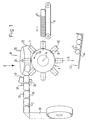
- Fig. 1 shows schematically a view of an embodiment of the device.
- FIG. 2 schematically shows a top view of the device according to FIG. 1 in viewing direction II of FIG. 1.
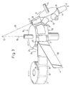
- Fig. 3 shows in perspective the feed station and the gluing station of the device.
- the device according to the exemplary embodiment is used to stick labels 2 onto conical peripheral surfaces of cups 4.
- the cups 4 are stacked and fed individually to a star 8 with plug-on bodies 10 for the cups, lying on a conveyor belt 6.
- the plug-on body 10 has a taper which is adapted to the taper of the interior of the cup and can be rotated about axes 12 which run radially to the axis of rotation 14 of the star 8.
- the cups placed on the plug-on bodies 10 are successively moved from the star 8 in the direction of arrow A to a gluing station 16 in which there is a label transfer drum 20 with a conical peripheral surface 22 which is to be rotated about its axis 18.
- suction openings 24 for the suction of labels 2 supplied by a feed station 26 are provided at circumferential distances that are greater than the length of the labels 2 in the circumferential direction.
- the conical peripheral surface 22 of the drum 20 runs in the running direction of the sucked-in labels 2 in the gluing station 16 next to the conical peripheral surface 28 of the cups 4.
- the cups 4 can be loosely rotated or driven about the axes 12. Because of the adapted taper of the drum takes place in the contact area of drum 20 and each cup 4 a rotation of the cup 4 about its taper axis 30 at peripheral speeds which are substantially equal to the peripheral speeds in the opposing areas of the cup 4 and the drum 20.
- the taper axes 18, 30 of the drum 20 and the cup 4 intersect at a common cone point 32.
- the labels 2 have curved upper edges 34 and 36 which, after the labels have been stuck onto the cups 4, run at right angles to the taper axes 30 of the cups 4.
- the labels 2 are fed to the feed station 26 on a carrier belt 38, from which they are released in the feed station 26 by deflecting the carrier belt around a deflection edge or deflection roller 40 running parallel to the conical peripheral surface 22 of the drum 20 in the feed station 26.
- the transport speed of the carrier belt 38 preferably corresponds to an average peripheral speed of the drum 20.
- the suction openings 24 only suck in the front regions of the labels 2 in the running direction of the labels 2.
- the side of the labels 2 to be glued to the cup 4 is provided with a pressure-sensitive adhesive layer (not shown), the adhesive force of which on the cups 4 is greater than the suction force through the openings 24 in the drum 20.
- the labeled cups 4 are removed from the plug-on bodies 10 in a receiving station 42 in the direction of arrow B - they fall down - and fed to a magazine 44.
Abstract
Description
Die Erfindung betrifft eine Vorrichtung zum Aufkleben von Etiketten auf konische Umfangsflächen von Gegenständen, insbesondere Bechern.The invention relates to a device for sticking labels onto conical peripheral surfaces of objects, in particular cups.
Es ist bekannt, die zu etikettierenden Gegenstände nacheinander in einer Aufklebstation mit von einem Trägerband zugeführten, durch Umlenken des Trägerbands abgelösten Etiketten zu bekleben, wobei die Gegenstände um ihre Konizitätsachse gedreht werden. Da die Umfangsgeschwindigkeiten der konischen Umfangsflächen der Gegenstände notwendigerweise verschieden sind, die Zuführungsgeschwindigkeiten der Etiketten entsprechend der Zuführungsgeschwindigkeit des Trägerbands aber konstant ist, ist ein unverzerrtes, faltenloses Aufbringen der Etiketten auf die konischen Umfangsflächen nicht möglich.It is known to adhere the items to be labeled one after the other in a gluing station to labels which have been fed in from a carrier tape and have been detached by deflecting the carrier tape, the items being rotated about their taper axis. Since the peripheral speeds of the conical peripheral surfaces of the objects are necessarily different, but the feed speeds of the labels are constant in accordance with the feed speed of the carrier tape, undistorted, wrinkle-free application of the labels to the conical peripheral surfaces is not possible.
Aufgabe der Erfindung ist es, eine Vorrichtung eingangs genannter Art anzugeben, die es gestattet, Etiketten verzerrungsfrei und faltenfrei auf konische Umfangsflächen von Gegenständen zu kleben.The object of the invention is to provide a device of the type mentioned at the outset which allows labels to be attached to conical circumferential surfaces of objects without distortion or wrinkles.
Zur Lösung dieser Aufgabe ist die Vorrichtung dadurch gekennzeichnet, daß sie eine um ihre Achse in Umlauf zu setzende Etiketten-Überführungstrommel mit einer konischen Umfangsfläche aufweist, in der sich Ansaugdurchbrechungen zum Ansaugen vereinzelt von einer Zuführungsstation zugeführter Etiketten befinden und daß die konische Umfangsfläche dieser Trommel in Laufrichtung der angesaugten Etiketten in einer Aufklebstation nächst der konischen Umfangsfläche eines zugeführten Gegenstands verläuft, der um seine Konizitätsachse mit Umfangsgeschwindigkeiten drehbar ist, die im wesentlichen gleich den Umfangsgeschwindigkeiten der Trommel in den einander gegenüberstehenden Bereichen des Gegenstands und der Trommel sind.To achieve this object, the device is characterized in that it has a label transfer drum to be rotated about its axis with a conical circumferential surface, in which there are suction openings for suction of labels fed from a feed station and that the conical circumferential surface of this drum is in The direction of travel of the sucked-in labels in a gluing station is next to the conical peripheral surface of a supplied object which is rotatable about its taper axis at peripheral speeds which are substantially equal to the peripheral speeds of the drum in the mutually opposing regions of the object and the drum.
Bei Anwendung der Erfindung tritt praktisch keine Relativbewegung zwischen den Umfangsgeschwindigkeiten der Trommel und den Umfangsgeschwindigkeiten des Gegenstands in den einander gegenüberstehenden Bereichen des Gegenstands und der Trommel auf, so daß die Etiketten verzerrungsfrei auf die Gegenstände zu übertragen sind. Dabei richtet sich der Grad der Konizität der Trommel nach dem Grad der Konizität der zu etikettierenden Gegenstände.When using the invention there is practically no relative movement between the peripheral speeds of the drum and the peripheral speeds of the article in the opposing regions of the article and the drum, so that the labels can be transferred to the articles without distortion. The degree of taper of the drum depends on the degree of taper of the objects to be labeled.
Um die Anpassung der Umfangsgeschwindigkeiten von Trommel und Gegenstand zu erreichen, schneiden sich bevorzugt die Konizitätsachsen der Trommel und des Gegenstands in einem gemeinsamen Kugelpunkt.In order to achieve the adaptation of the peripheral speeds of the drum and the object, the taper axes of the drum and the object preferably intersect at a common ball point.
Mit der Vorrichtung kann man auf die Gegenstände Etiketten kleben, die derart gekrümmte Ober- und/oder Unterkanten haben, daß diese Kanten nach dem Aufkleben auf die Gegenstände rechtwinklig zu den Konizitätsachsen der Gegenstände verlaufen. Die Ober- und/oder Unterkanten können aber auch geradlinig oder - wie bei kreisförmigen Etiketten - rund sein.The device can be used to stick labels to the objects which have such curved upper and / or lower edges that these edges, after being glued to the objects, run at right angles to the taper axes of the objects. The top and / or bottom edges can also be straight or - as with circular labels - round.
Um zu erreichen, daß die Etiketten von einem Trägerband durch Umlenken des Trägerbands der Trommel so zugeführt werden, daß sie der konischen Umfangsfläche der Trommel im wesentlichen glatt anliegen, werden bevorzugt die Etiketten der Zuführungsstation auf einem Trägerband zugeführt, von dem sie in der Zuführungsstation durch Umlenken des Trägerbands um eine parallel zur konischen Umfangsfläche der Trommel in der Zuführungsstation verlaufende Umlenkkrümmungsachse des Trägerbands gelöst werden, vorzugsweise bei einer Transportgeschwindigkeit, die einer mittleren Umfangsgeschwindigkeit der Trommel entspricht. Jedenfalls soll die Transportgeschwindigkeit zwischen der kleinsten und der größten Umfangsgeschwindigkeit der Trommel liegen. Die Etiketten werden dann im Bereich des kleineren Trommeldurchmessers der Umfangsfläche der Trommel mit einer höheren Geschwindigkeit zugeführt als die entsprechende Umfangsgeschwindigkeit der Trommel und der Bereich des größeren Trommeldurchmessers mit einer niedrigeren Geschwindigkeit zugeführt als die entsprechende Umfangsgeschwindigkeit der Trommel. Im Bereich des kleineren Trommeldurchmessers ergeben sich dadurch Wellungen oder Schlaufen, im Bereich des größeren Trommeldurchmessers ein Schlupf. Die Schlaufen (Wellungen) und der Schlupf sind von der Konizität der Trommel abhängig und von der Transportgeschwindigkeit des Trägerbands relativ zu den Umfangsgeschwindigkeiten der Trommel.In order to ensure that the labels are fed from a carrier tape by deflecting the carrier tape to the drum so that they lie substantially smoothly against the conical peripheral surface of the drum, the labels are preferably fed to the feed station on a carrier tape, from which they pass through in the feed station Deflection of the carrier belt around a deflection curve axis of the carrier belt running parallel to the conical peripheral surface of the drum in the feed station can be released, preferably at a transport speed which corresponds to an average peripheral speed of the drum. In any case, the transport speed should be between the smallest and the greatest peripheral speed of the drum. The labels are then in the area of the smaller drum diameter of the peripheral surface of the drum at a higher speed fed as the corresponding peripheral speed of the drum and the area of the larger drum diameter supplied at a lower speed than the corresponding peripheral speed of the drum. This results in corrugations or loops in the area of the smaller drum diameter, and slippage in the area of the larger drum diameter. The loops (corrugations) and the slip depend on the taper of the drum and on the transport speed of the carrier tape relative to the peripheral speeds of the drum.
Sind die Schlaufen (Wellungen) und der Schlupf störend, können sie praktisch zu Null gebracht werden, wenn die Ansaugdurchbrechungen in der Zuführungsstation nur die in Laufrichtung der Etiketten vorderen Bereiche (etwa 1/10 ihrer Länge in Laufrichtung) der Etiketten ansaugen. Die Etiketten legen sich dann praktisch flach an die Umfangsfläche der Trommel an.If the loops (corrugations) and slippage are disruptive, they can be brought to practically zero if the suction openings in the feed station only suck in the front areas of the labels in the running direction (approximately 1/10 of their length in the running direction) of the labels. The labels then lay practically flat on the peripheral surface of the drum.
Damit sich die Etiketten in der Aufklebstation von der Trommel lösen, ist bevorzugt die auf die Gegenstände zu klebende Seite der Etiketten mit einer Haftklebstoffschicht versehen, deren Haftkraft auf den Gegenständen größer ist als die Ansaugkraft der Trommel.So that the labels in the gluing station detach from the drum, the side of the labels to be glued to the objects is preferably provided with a layer of pressure-sensitive adhesive, the adhesive force of which on the objects is greater than the suction force of the drum.
Zum Zuführen der Gegenstände zu der Aufklebstation befindet sich bevorzugt in der Aufklebstation ein schrittweise drehbarer Stern zur Zuführung und Abführung der Gegenstände in Tangentialrichtung der Trommel.To feed the objects to the gluing station, there is preferably a star which can be rotated step by step in the gluing station for feeding and removing the objects in the tangential direction of the drum.
Die Trommel ist auf ihrer Umfangsfläche vorzugsweise mit einer Schicht aus einem elastomeren Material, bevorzugt Gummi, überzogen. Eine solche Schicht bewirkt zum einen eine bessere Fixierung der Etiketten auf der Trommel, zum anderen werden die Etiketten durch sie gleichmäßig an die Becher angedrückt.The drum is preferably covered on its peripheral surface with a layer of an elastomeric material, preferably rubber. Such a layer on the one hand brings about a better fixation of the labels on the drum, and on the other hand it evenly presses the labels onto the cups.
Die Erfindung wird im folgenden an einem Ausführungsbeispiel unter Hinweis auf die beigefügten Zeichnungen beschrieben.The invention is described below using an exemplary embodiment with reference to the accompanying drawings.
Fig. 1 zeigt schematisch eine Ansicht einer Ausführungsform der Vorrichtung.Fig. 1 shows schematically a view of an embodiment of the device.
Fig. 2 zeigt schematisch eine Aufsicht auf die Vorrichtung nach Fig. 1 in Blickrichtung II der Fig. 1.FIG. 2 schematically shows a top view of the device according to FIG. 1 in viewing direction II of FIG. 1.
Fig. 3 Zeigt perspektivisch die Zuführungsstation und die Aufklebstation der Vorrichtung.Fig. 3 shows in perspective the feed station and the gluing station of the device.
Die Vorrichtung nach dem Ausführungsbeispiel dient dem Aufkleben von Etiketten 2 auf konische Umfangsflächen von Bechern 4. Die Becher 4 werden gestapelt auf einem Transportband 6 liegend einzeln einem Stern 8 mit Aufsteckkörpern 10 für die Becher zugeführt. Die Aufsteckkörper 10 haben eine Konizität, die der Konizität des Innenraums der Becher angepaßt ist und sind um Achsen 12 drehbar, die radial zur Drehachse 14 des Sterns 8 verlaufen. Die auf die Aufsteckkörper 10 aufgesteckten Becher werden nacheinander von dem Stern 8 in Pfeilrichtung A zu einer Aufklebstation 16 bewegt, in der sich eine um ihre Achse 18 in Umlauf zu setzende Etiketten-Überführungstrommel 20 mit einer konischen Umfangsfläche 22 befindet. In dieser konischen Umfangsfläche 22 sind in Umfangsabständen, die größer als die Länge der Etiketten 2 in Umfangsrichtung sind, Ansaugdurchbrechungen 24 (Löcher oder Schlitze) zum Ansaugen vereinzelt von einer Zuführungsstation 26 zugeführter Etiketten 2 vorgesehen. Die konische Umfangsfläche 22 der Trommel 20 verläuft in Laufrichtung der angesaugten Etiketten 2 in der Aufklebstation 16 nächst der konischen Umfangsfläche 28 der Becher 4. Um die Achsen 12 sind die Becher 4 lose drehbar oder angetrieben. Wegen der angepaßten Konizität der Trommel erfolgt im Kontaktbereich von Trommel 20 und jeweiligem Becher 4 eine Drehung des Bechers 4 um seine Konizitätsachse 30 mit Umfangsgeschwindigkeiten, die im wesentlichen gleich den Umfangsgeschwindigkeiten in den einander gegenüberstehenden Bereichen des Bechers 4 und der Trommel 20 sind. Die Konizitätsachsen 18, 30 der Trommel 20 und des Bechers 4 schneiden sich in einem gemeinsamen Kegelpunkt 32.The device according to the exemplary embodiment is used to stick
Die Etiketten 2 weisen gekrümmte Oberkanten 34 und 36 auf, die nach dem Aufkleben der Etiketten auf die Becher 4 rechtwinklig zu den Konizitätsachsen 30 der Becher 4 verlaufen.The
Die Etiketten 2 werden der Zuführungsstation 26 auf einem Trägerband 38 zugeführt, von dem sie in der Zuführungsstation 26 durch Umlenken des Trägerbands um eine parallel zur konischen Umfangsfläche 22 der Trommel 20 in der Zuführungsstation 26 verlaufende Umlenkkante oder Umlenkrolle 40 gelöst werden. Die Transportgeschwindigkeit des Trägerbands 38 entspricht vorzugsweise einer mittleren Umfangsgeschwindigkeit der Trommel 20.The
Die Ansaugdurchbrechungen 24 saugen in der Zuführungsstation 26 nur die in Laufrichtung der Etiketten 2 vorderen Bereiche der Etiketten 2 an.In the
Die auf die Becher 4 zu klebende Seite der Etiketten 2 ist mit einer - nicht dargestellten - Haftklebstoffschicht versehen, deren Haftkraft auf den Bechern 4 größer ist als die Ansaugkraft durch die Durchbrechungen 24 in der Trommel 20.The side of the
Die etikettierten Becher 4 werden von den Aufsteckkörpern 10 in einer Aufnahmestation 42 in Pfeilrichtung B abgenommen - sie fallen herunter - und einem Magazin 44 zugeführt.The labeled
Claims (9)
dadurch gekennzeichnet,
daß sie eine um ihre Achse (18) in Umlauf zu setzende Etiketten-Überführungstrommel (20) mit einer konischen Umfangsfläche (22) aufweist, in der sich Ansaugdurchbrechungen (24) zum Ansaugen vereinzelt von einer Zuführungsstation (26) zugeführter Etiketten (2) befinden und daß die konische Umfangsfläche (22) dieser Trommel (20) in Laufrichtung der angesaugten Etiketten (2) in einer Aufklebstation (16) nächst der konischen Umfangsfläche (28) eines zugeführten Gegenstands (4) verläuft, der um seine Konizitätsachse (30) mit Umfangsgeschwindigkeiten drehbar ist, die im wesentlichen gleich den Umfangsgeschwindigkeiten der Trommel (20) in den einander gegenüberstehenden Bereichen des Gegenstands (4) und der Trommel (20) sind.Device for sticking labels (2) on conical peripheral surfaces (28) of objects (4), in particular cups,
characterized,
that it has a label transfer drum (20) to be put into circulation about its axis (18) with a conical peripheral surface (22) in which there are suction openings (24) for the suction of labels (2) fed from a feed station (26) and that the conical circumferential surface (22) of this drum (20) runs in the direction of travel of the sucked-in labels (2) in a gluing station (16) next to the conical circumferential surface (28) of a supplied object (4), which also extends around its conical axis (30) Peripheral speeds is rotatable, which is substantially equal to the peripheral speeds of the drum (20) in each other opposite areas of the object (4) and the drum (20).
Priority Applications (1)
| Application Number | Priority Date | Filing Date | Title |
|---|---|---|---|
| AT92100212T ATE97373T1 (en) | 1991-02-28 | 1992-01-08 | DEVICE FOR STICKING LABELS ON CONICAL SURFACE SURFACE OF OBJECTS, ESPECIALLY CUPS. |
Applications Claiming Priority (2)
| Application Number | Priority Date | Filing Date | Title |
|---|---|---|---|
| DE4106387A DE4106387A1 (en) | 1991-02-28 | 1991-02-28 | DEVICE FOR STICKING LABELS ON CONICAL SURFACES OF OBJECTS, IN PARTICULAR BOWLS |
| DE4106387 | 1991-02-28 |
Publications (2)
| Publication Number | Publication Date |
|---|---|
| EP0501105A1 true EP0501105A1 (en) | 1992-09-02 |
| EP0501105B1 EP0501105B1 (en) | 1993-11-18 |
Family
ID=6426146
Family Applications (1)
| Application Number | Title | Priority Date | Filing Date |
|---|---|---|---|
| EP92100212A Expired - Lifetime EP0501105B1 (en) | 1991-02-28 | 1992-01-08 | Device for applying labels on conical surfaces of objects, particularly of plastic cups |
Country Status (5)
| Country | Link |
|---|---|
| EP (1) | EP0501105B1 (en) |
| AT (1) | ATE97373T1 (en) |
| DE (2) | DE4106387A1 (en) |
| ES (1) | ES2046899T3 (en) |
| HK (1) | HK1001894A1 (en) |
Cited By (13)
| Publication number | Priority date | Publication date | Assignee | Title |
|---|---|---|---|---|
| DE4409952C1 (en) * | 1994-03-23 | 1995-02-02 | Hatto Hartnagel | Labelling apparatus |
| DE19524967A1 (en) * | 1995-07-08 | 1997-01-09 | Hatto Hartnagel | Method and appliance for applying single labels to curved outer surfaces of objects - involves applying labels to rotary support, disc and rotary receiver bodies, heater |
| EP0806365A1 (en) * | 1996-05-09 | 1997-11-12 | KRONES AG Hermann Kronseder Maschinenfabrik | Labelling machine for open containers, particularly cups |
| EP0895937A1 (en) | 1997-08-04 | 1999-02-10 | KRONES AG Hermann Kronseder Maschinenfabrik | Device for applying labels to conical surfaces of articles |
| WO2000003919A1 (en) * | 1998-07-14 | 2000-01-27 | Lts Lohmann Therapie-Systeme Ag | Method and device for producing surface-adhesive products from laminates, the transfer thereof to a cover foil and final fabrication |
| EP1129952A2 (en) * | 1999-12-24 | 2001-09-05 | Cansol AG | Method and apparatus for applying decals on containers |
| EP1179481A1 (en) * | 2000-08-10 | 2002-02-13 | Sasib Labelling Machinery S.p.A. | A method and apparatus for adjusting the inclination of the label for conical or non-cylindrical containers |
| US7269930B2 (en) | 2004-06-19 | 2007-09-18 | Khs Maschinen- Und Anlagenbau Ag | Beverage bottling plant for filling bottles with a liquid beverage filling material having a device for labeling of containers with continuous feeding of labels, even upon some label supply arrangements being emptied of labels |
| WO2014040741A1 (en) * | 2012-09-13 | 2014-03-20 | H+E PACKTEC GmbH | Method and device for labelling a conical plastic container and banderole provided for this |
| CN104229247A (en) * | 2014-09-04 | 2014-12-24 | 无锡市张泾宇钢机械厂 | Non-setting adhesive labeling system |
| CN110356698A (en) * | 2018-04-10 | 2019-10-22 | 万臣塑料制品(上海)有限公司 | The micro contraction labeling pipe manufacturing method of one kind and labeling pipe and preheating device for labeling |
| CN110498102A (en) * | 2019-07-16 | 2019-11-26 | 苏州翌恒生物科技有限公司 | A kind of device and its labeling method that heparin tube is labelled by pneumatic mode |
| CN113978871A (en) * | 2021-11-22 | 2022-01-28 | 广州市冠浩机械设备有限公司 | Conical cup labeling machine |
Families Citing this family (1)
| Publication number | Priority date | Publication date | Assignee | Title |
|---|---|---|---|---|
| DE9413747U1 (en) * | 1994-08-25 | 1995-05-04 | Zweckform Etikettiertechnik | Device for labeling and printing an object |
Citations (1)
| Publication number | Priority date | Publication date | Assignee | Title |
|---|---|---|---|---|
| US4332635A (en) * | 1980-07-03 | 1982-06-01 | American Can Company | Cup labeling method and apparatus |
-
1991
- 1991-02-28 DE DE4106387A patent/DE4106387A1/en not_active Withdrawn
-
1992
- 1992-01-08 AT AT92100212T patent/ATE97373T1/en not_active IP Right Cessation
- 1992-01-08 DE DE92100212T patent/DE59200025D1/en not_active Expired - Fee Related
- 1992-01-08 EP EP92100212A patent/EP0501105B1/en not_active Expired - Lifetime
- 1992-01-08 ES ES199292100212T patent/ES2046899T3/en not_active Expired - Lifetime
-
1998
- 1998-02-06 HK HK98100913A patent/HK1001894A1/en not_active IP Right Cessation
Patent Citations (1)
| Publication number | Priority date | Publication date | Assignee | Title |
|---|---|---|---|---|
| US4332635A (en) * | 1980-07-03 | 1982-06-01 | American Can Company | Cup labeling method and apparatus |
Cited By (18)
| Publication number | Priority date | Publication date | Assignee | Title |
|---|---|---|---|---|
| DE4409952C1 (en) * | 1994-03-23 | 1995-02-02 | Hatto Hartnagel | Labelling apparatus |
| DE19524967A1 (en) * | 1995-07-08 | 1997-01-09 | Hatto Hartnagel | Method and appliance for applying single labels to curved outer surfaces of objects - involves applying labels to rotary support, disc and rotary receiver bodies, heater |
| EP0806365A1 (en) * | 1996-05-09 | 1997-11-12 | KRONES AG Hermann Kronseder Maschinenfabrik | Labelling machine for open containers, particularly cups |
| EP0895937A1 (en) | 1997-08-04 | 1999-02-10 | KRONES AG Hermann Kronseder Maschinenfabrik | Device for applying labels to conical surfaces of articles |
| WO2000003919A1 (en) * | 1998-07-14 | 2000-01-27 | Lts Lohmann Therapie-Systeme Ag | Method and device for producing surface-adhesive products from laminates, the transfer thereof to a cover foil and final fabrication |
| EP1129952A2 (en) * | 1999-12-24 | 2001-09-05 | Cansol AG | Method and apparatus for applying decals on containers |
| EP1129952A3 (en) * | 1999-12-24 | 2001-09-12 | Cansol AG | Method and apparatus for applying decals on containers |
| US6571673B2 (en) | 2000-08-10 | 2003-06-03 | Sig Alfa S.P.A | Method and apparatus for adjusting the inclination of the label in a labeling machine for conical or non-cylindrical containers |
| EP1179481A1 (en) * | 2000-08-10 | 2002-02-13 | Sasib Labelling Machinery S.p.A. | A method and apparatus for adjusting the inclination of the label for conical or non-cylindrical containers |
| US7269930B2 (en) | 2004-06-19 | 2007-09-18 | Khs Maschinen- Und Anlagenbau Ag | Beverage bottling plant for filling bottles with a liquid beverage filling material having a device for labeling of containers with continuous feeding of labels, even upon some label supply arrangements being emptied of labels |
| WO2014040741A1 (en) * | 2012-09-13 | 2014-03-20 | H+E PACKTEC GmbH | Method and device for labelling a conical plastic container and banderole provided for this |
| RU2650164C2 (en) * | 2012-09-13 | 2018-04-09 | Нсм Пактек Гмбх | Method and device for labelling a conical plastic container and banderole provided for this |
| CN104229247A (en) * | 2014-09-04 | 2014-12-24 | 无锡市张泾宇钢机械厂 | Non-setting adhesive labeling system |
| CN104229247B (en) * | 2014-09-04 | 2016-03-09 | 无锡纳润特科技有限公司 | Pressure sensitive adhesive mark system |
| CN110356698A (en) * | 2018-04-10 | 2019-10-22 | 万臣塑料制品(上海)有限公司 | The micro contraction labeling pipe manufacturing method of one kind and labeling pipe and preheating device for labeling |
| CN110498102A (en) * | 2019-07-16 | 2019-11-26 | 苏州翌恒生物科技有限公司 | A kind of device and its labeling method that heparin tube is labelled by pneumatic mode |
| CN113978871A (en) * | 2021-11-22 | 2022-01-28 | 广州市冠浩机械设备有限公司 | Conical cup labeling machine |
| CN113978871B (en) * | 2021-11-22 | 2022-11-22 | 广州市冠浩机械设备有限公司 | Conical cup labeling machine |
Also Published As
| Publication number | Publication date |
|---|---|
| EP0501105B1 (en) | 1993-11-18 |
| DE59200025D1 (en) | 1993-12-23 |
| ATE97373T1 (en) | 1993-12-15 |
| DE4106387A1 (en) | 1992-09-03 |
| HK1001894A1 (en) | 1998-07-17 |
| ES2046899T3 (en) | 1994-02-01 |
Similar Documents
| Publication | Publication Date | Title |
|---|---|---|
| EP0501105B1 (en) | Device for applying labels on conical surfaces of objects, particularly of plastic cups | |
| DE102011107265A1 (en) | Method for producing packages of bottles, involves partially providing adhesive coat on sub region, and drawing containers near each other and pressing containers against each other such that containers are connected with each other by coat | |
| DE102006011870B4 (en) | Singling device and method for piecewise provision of plate-shaped objects | |
| EP2729371A1 (en) | Method for producing packs of containers, and pack thus obtained | |
| DE2219775C3 (en) | Transfer conveyor for workpieces that are closed flush on at least one face | |
| DE4409952C1 (en) | Labelling apparatus | |
| EP0006505B1 (en) | Labelling apparatus for flat articles, such us audio cassettes, video cassettes or similar articles | |
| DE4042100C2 (en) | Method and device for applying self-adhesive labels and use of a device for self-adhesive labels | |
| EP0852553B1 (en) | Device for automatically suspending sacks | |
| DE4116784C2 (en) | ||
| DE2747265A1 (en) | Laminated photopolymer cover foil handling device - has roller on one side of conveyor path with belt to transfer foil | |
| DE3715920A1 (en) | Labelling machine | |
| EP0908876A2 (en) | Process and apparatus for gluing a first flat disc-shaped synthetic substrate to a second similar substrate for forming a digital video disc | |
| DE1486155A1 (en) | Labeling machine | |
| DE2651911C3 (en) | Device for pressing glued labels or foils onto objects | |
| DE19653779A1 (en) | Cheese round labelling machine | |
| EP0775657A2 (en) | Device for aligning flat mail objects | |
| EP0450328B1 (en) | Device for feeding a label to an object | |
| DE4020847A1 (en) | Labelling machine with suction plate removing labels - has specially arranged suction holes for even application | |
| DE2451452A1 (en) | PROCEDURE FOR COVERING GLASS CONTAINERS | |
| EP1274627B1 (en) | Device and method for applying a securing element to a label | |
| DE4024331A1 (en) | Sorter, distributor and transporter for packaging units - consists of main and parallel subsidiary conveyor belts with suction pads and release unit | |
| DE4007019C2 (en) | Process for feeding print media with slip holes onto attachments on objects | |
| CH627698A5 (en) | Labelling apparatus with continuously working kinematics | |
| DE10245167A1 (en) | Device for sorting waste |
Legal Events
| Date | Code | Title | Description |
|---|---|---|---|
| PUAI | Public reference made under article 153(3) epc to a published international application that has entered the european phase |
Free format text: ORIGINAL CODE: 0009012 |
|
| AK | Designated contracting states |
Kind code of ref document: A1 Designated state(s): AT BE CH DE ES FR GB IT LI NL |
|
| 17P | Request for examination filed |
Effective date: 19920908 |
|
| 17Q | First examination report despatched |
Effective date: 19921230 |
|
| GRAA | (expected) grant |
Free format text: ORIGINAL CODE: 0009210 |
|
| AK | Designated contracting states |
Kind code of ref document: B1 Designated state(s): AT BE CH DE ES FR GB IT LI NL |
|
| REF | Corresponds to: |
Ref document number: 97373 Country of ref document: AT Date of ref document: 19931215 Kind code of ref document: T |
|
| REF | Corresponds to: |
Ref document number: 59200025 Country of ref document: DE Date of ref document: 19931223 |
|
| REG | Reference to a national code |
Ref country code: ES Ref legal event code: FG2A Ref document number: 2046899 Country of ref document: ES Kind code of ref document: T3 |
|
| ITF | It: translation for a ep patent filed |
Owner name: JACOBACCI CASETTA & PERANI S.P.A. |
|
| ET | Fr: translation filed | ||
| GBT | Gb: translation of ep patent filed (gb section 77(6)(a)/1977) |
Effective date: 19940224 |
|
| PLBE | No opposition filed within time limit |
Free format text: ORIGINAL CODE: 0009261 |
|
| STAA | Information on the status of an ep patent application or granted ep patent |
Free format text: STATUS: NO OPPOSITION FILED WITHIN TIME LIMIT |
|
| 26N | No opposition filed | ||
| REG | Reference to a national code |
Ref country code: CH Ref legal event code: PUE Owner name: STEINBEIS PACKAGING GMBH TRANSFER- STEINBEIS PPL G Ref country code: CH Ref legal event code: PFA Free format text: ZWECKFORM ETIKETTIERTECHNIK GMBH TRANSFER- STEINBEIS PACKAGING GMBH |
|
| BECH | Be: change of holder |
Free format text: 19991103 *STEINBEIS PPL G.M.B.H. |
|
| NLS | Nl: assignments of ep-patents |
Owner name: STEINBEIS PPL GMBH |
|
| NLT1 | Nl: modifications of names registered in virtue of documents presented to the patent office pursuant to art. 16 a, paragraph 1 |
Owner name: STEINBEIS PACKAGING GMBH |
|
| REG | Reference to a national code |
Ref country code: GB Ref legal event code: 732E |
|
| REG | Reference to a national code |
Ref country code: FR Ref legal event code: TP Ref country code: FR Ref legal event code: CD Ref country code: FR Ref legal event code: CA |
|
| REG | Reference to a national code |
Ref country code: GB Ref legal event code: IF02 |
|
| PGFP | Annual fee paid to national office [announced via postgrant information from national office to epo] |
Ref country code: DE Payment date: 20021213 Year of fee payment: 12 |
|
| PGFP | Annual fee paid to national office [announced via postgrant information from national office to epo] |
Ref country code: FR Payment date: 20021216 Year of fee payment: 12 Ref country code: CH Payment date: 20021216 Year of fee payment: 12 |
|
| PGFP | Annual fee paid to national office [announced via postgrant information from national office to epo] |
Ref country code: AT Payment date: 20021218 Year of fee payment: 12 |
|
| PGFP | Annual fee paid to national office [announced via postgrant information from national office to epo] |
Ref country code: ES Payment date: 20021223 Year of fee payment: 12 |
|
| PGFP | Annual fee paid to national office [announced via postgrant information from national office to epo] |
Ref country code: GB Payment date: 20030107 Year of fee payment: 12 |
|
| PGFP | Annual fee paid to national office [announced via postgrant information from national office to epo] |
Ref country code: BE Payment date: 20030122 Year of fee payment: 12 |
|
| PGFP | Annual fee paid to national office [announced via postgrant information from national office to epo] |
Ref country code: NL Payment date: 20030131 Year of fee payment: 12 |
|
| PG25 | Lapsed in a contracting state [announced via postgrant information from national office to epo] |
Ref country code: GB Free format text: LAPSE BECAUSE OF NON-PAYMENT OF DUE FEES Effective date: 20040108 Ref country code: AT Free format text: LAPSE BECAUSE OF NON-PAYMENT OF DUE FEES Effective date: 20040108 |
|
| PG25 | Lapsed in a contracting state [announced via postgrant information from national office to epo] |
Ref country code: ES Free format text: LAPSE BECAUSE OF NON-PAYMENT OF DUE FEES Effective date: 20040109 |
|
| PG25 | Lapsed in a contracting state [announced via postgrant information from national office to epo] |
Ref country code: LI Free format text: LAPSE BECAUSE OF NON-PAYMENT OF DUE FEES Effective date: 20040131 Ref country code: CH Free format text: LAPSE BECAUSE OF NON-PAYMENT OF DUE FEES Effective date: 20040131 Ref country code: BE Free format text: LAPSE BECAUSE OF NON-PAYMENT OF DUE FEES Effective date: 20040131 |
|
| BERE | Be: lapsed |
Owner name: *STEINBEIS PPL G.M.B.H. Effective date: 20040131 |
|
| PG25 | Lapsed in a contracting state [announced via postgrant information from national office to epo] |
Ref country code: NL Free format text: LAPSE BECAUSE OF NON-PAYMENT OF DUE FEES Effective date: 20040801 |
|
| PG25 | Lapsed in a contracting state [announced via postgrant information from national office to epo] |
Ref country code: DE Free format text: LAPSE BECAUSE OF NON-PAYMENT OF DUE FEES Effective date: 20040803 |
|
| GBPC | Gb: european patent ceased through non-payment of renewal fee |
Effective date: 20040108 |
|
| REG | Reference to a national code |
Ref country code: CH Ref legal event code: PL |
|
| PG25 | Lapsed in a contracting state [announced via postgrant information from national office to epo] |
Ref country code: FR Free format text: LAPSE BECAUSE OF NON-PAYMENT OF DUE FEES Effective date: 20040930 |
|
| NLV4 | Nl: lapsed or anulled due to non-payment of the annual fee |
Effective date: 20040801 |
|
| REG | Reference to a national code |
Ref country code: FR Ref legal event code: ST |
|
| PG25 | Lapsed in a contracting state [announced via postgrant information from national office to epo] |
Ref country code: IT Free format text: LAPSE BECAUSE OF NON-PAYMENT OF DUE FEES;WARNING: LAPSES OF ITALIAN PATENTS WITH EFFECTIVE DATE BEFORE 2007 MAY HAVE OCCURRED AT ANY TIME BEFORE 2007. THE CORRECT EFFECTIVE DATE MAY BE DIFFERENT FROM THE ONE RECORDED. Effective date: 20050108 |
|
| REG | Reference to a national code |
Ref country code: ES Ref legal event code: FD2A Effective date: 20040109 |