EP0498996A1 - Apparatus and methods for non-invasive examination - Google Patents
Apparatus and methods for non-invasive examination Download PDFInfo
- Publication number
- EP0498996A1 EP0498996A1 EP91311648A EP91311648A EP0498996A1 EP 0498996 A1 EP0498996 A1 EP 0498996A1 EP 91311648 A EP91311648 A EP 91311648A EP 91311648 A EP91311648 A EP 91311648A EP 0498996 A1 EP0498996 A1 EP 0498996A1
- Authority
- EP
- European Patent Office
- Prior art keywords
- temperature
- signals
- lead
- electrode
- radio frequency
- Prior art date
- Legal status (The legal status is an assumption and is not a legal conclusion. Google has not performed a legal analysis and makes no representation as to the accuracy of the status listed.)
- Granted
Links
Images


Classifications
-
- G—PHYSICS
- G01—MEASURING; TESTING
- G01R—MEASURING ELECTRIC VARIABLES; MEASURING MAGNETIC VARIABLES
- G01R33/00—Arrangements or instruments for measuring magnetic variables
- G01R33/20—Arrangements or instruments for measuring magnetic variables involving magnetic resonance
- G01R33/44—Arrangements or instruments for measuring magnetic variables involving magnetic resonance using nuclear magnetic resonance [NMR]
- G01R33/48—NMR imaging systems
- G01R33/54—Signal processing systems, e.g. using pulse sequences ; Generation or control of pulse sequences; Operator console
- G01R33/56—Image enhancement or correction, e.g. subtraction or averaging techniques, e.g. improvement of signal-to-noise ratio and resolution
- G01R33/567—Image enhancement or correction, e.g. subtraction or averaging techniques, e.g. improvement of signal-to-noise ratio and resolution gated by physiological signals, i.e. synchronization of acquired MR data with periodical motion of an object of interest, e.g. monitoring or triggering system for cardiac or respiratory gating
- G01R33/5673—Gating or triggering based on a physiological signal other than an MR signal, e.g. ECG gating or motion monitoring using optical systems for monitoring the motion of a fiducial marker
-
- A—HUMAN NECESSITIES
- A61—MEDICAL OR VETERINARY SCIENCE; HYGIENE
- A61B—DIAGNOSIS; SURGERY; IDENTIFICATION
- A61B5/00—Measuring for diagnostic purposes; Identification of persons
- A61B5/05—Detecting, measuring or recording for diagnosis by means of electric currents or magnetic fields; Measuring using microwaves or radio waves
- A61B5/055—Detecting, measuring or recording for diagnosis by means of electric currents or magnetic fields; Measuring using microwaves or radio waves involving electronic [EMR] or nuclear [NMR] magnetic resonance, e.g. magnetic resonance imaging
-
- A—HUMAN NECESSITIES
- A61—MEDICAL OR VETERINARY SCIENCE; HYGIENE
- A61B—DIAGNOSIS; SURGERY; IDENTIFICATION
- A61B5/00—Measuring for diagnostic purposes; Identification of persons
- A61B5/103—Detecting, measuring or recording devices for testing the shape, pattern, colour, size or movement of the body or parts thereof, for diagnostic purposes
- A61B5/11—Measuring movement of the entire body or parts thereof, e.g. head or hand tremor, mobility of a limb
- A61B5/113—Measuring movement of the entire body or parts thereof, e.g. head or hand tremor, mobility of a limb occurring during breathing
- A61B5/1135—Measuring movement of the entire body or parts thereof, e.g. head or hand tremor, mobility of a limb occurring during breathing by monitoring thoracic expansion
-
- A—HUMAN NECESSITIES
- A61—MEDICAL OR VETERINARY SCIENCE; HYGIENE
- A61B—DIAGNOSIS; SURGERY; IDENTIFICATION
- A61B5/00—Measuring for diagnostic purposes; Identification of persons
- A61B5/24—Detecting, measuring or recording bioelectric or biomagnetic signals of the body or parts thereof
- A61B5/316—Modalities, i.e. specific diagnostic methods
- A61B5/318—Heart-related electrical modalities, e.g. electrocardiography [ECG]
- A61B5/346—Analysis of electrocardiograms
- A61B5/349—Detecting specific parameters of the electrocardiograph cycle
- A61B5/352—Detecting R peaks, e.g. for synchronising diagnostic apparatus; Estimating R-R interval
-
- A—HUMAN NECESSITIES
- A61—MEDICAL OR VETERINARY SCIENCE; HYGIENE
- A61B—DIAGNOSIS; SURGERY; IDENTIFICATION
- A61B5/00—Measuring for diagnostic purposes; Identification of persons
- A61B5/41—Detecting, measuring or recording for evaluating the immune or lymphatic systems
- A61B5/411—Detecting or monitoring allergy or intolerance reactions to an allergenic agent or substance
-
- G—PHYSICS
- G01—MEASURING; TESTING
- G01R—MEASURING ELECTRIC VARIABLES; MEASURING MAGNETIC VARIABLES
- G01R33/00—Arrangements or instruments for measuring magnetic variables
- G01R33/20—Arrangements or instruments for measuring magnetic variables involving magnetic resonance
- G01R33/28—Details of apparatus provided for in groups G01R33/44 - G01R33/64
-
- A—HUMAN NECESSITIES
- A61—MEDICAL OR VETERINARY SCIENCE; HYGIENE
- A61B—DIAGNOSIS; SURGERY; IDENTIFICATION
- A61B5/00—Measuring for diagnostic purposes; Identification of persons
- A61B5/72—Signal processing specially adapted for physiological signals or for diagnostic purposes
- A61B5/7271—Specific aspects of physiological measurement analysis
- A61B5/7285—Specific aspects of physiological measurement analysis for synchronising or triggering a physiological measurement or image acquisition with a physiological event or waveform, e.g. an ECG signal
-
- A—HUMAN NECESSITIES
- A61—MEDICAL OR VETERINARY SCIENCE; HYGIENE
- A61B—DIAGNOSIS; SURGERY; IDENTIFICATION
- A61B6/00—Apparatus for radiation diagnosis, e.g. combined with radiation therapy equipment
- A61B6/54—Control of apparatus or devices for radiation diagnosis
- A61B6/541—Control of apparatus or devices for radiation diagnosis involving acquisition triggered by a physiological signal
-
- Y—GENERAL TAGGING OF NEW TECHNOLOGICAL DEVELOPMENTS; GENERAL TAGGING OF CROSS-SECTIONAL TECHNOLOGIES SPANNING OVER SEVERAL SECTIONS OF THE IPC; TECHNICAL SUBJECTS COVERED BY FORMER USPC CROSS-REFERENCE ART COLLECTIONS [XRACs] AND DIGESTS
- Y10—TECHNICAL SUBJECTS COVERED BY FORMER USPC
- Y10S—TECHNICAL SUBJECTS COVERED BY FORMER USPC CROSS-REFERENCE ART COLLECTIONS [XRACs] AND DIGESTS
- Y10S128/00—Surgery
- Y10S128/901—Suppression of noise in electric signal
Definitions
- the present invention relates to apparatus and methods for non-invasive examination.
- it relates to apparatus and methods for cardiac gated magnetic resonance imaging and will be described with particular reference thereto.
- the invention finds application in other non-invasive examination techniques.
- Magnetic resonance imaging sequences commonly include the application of a radio frequency pulse concurrently with a slice select magnetic field gradient pulse.
- a phase encode magnetic field gradient pulse encodes phase into the nuclei induced resonance by the radio frequency pulse.
- Another radio frequency pulse is applied to invert the magnetic resonance and cause a magnetic resonance echo.
- the echo is read in the presence of a read magnetic field gradient pulse.
- Dephasing magnetic field gradient pulses in the slice select and read direction are commonly applied with an opposite polarity between the slice select and read gradient pulses. This sequence is repeated a multiplicity of times, each time with a different amplitude phase encode magnetic field gradient in order to generate a corresponding multiplicity of differently phase encoded views.
- Anatomical movement such as cardiac and respiratory motion, tends to degrade the resultant images.
- the amount of degradation is related to the amount or magnitude of physiological displacement from view to view, the rate of movement, and the like.
- Various anatomical condition monitors have been utilized to control the collection, processing, or use of magnetic resonance and other non-invasive imaging data in accordance with physiological motion. See for example, U.S. Patent Nos. 4,763,075 and 4,545,384.
- a patient's cardiac cycle is normally sensed with electro-cardiographic electrodes mounted to the patient's skin and connected by electrically conductive leads to processing circuitry.
- the electrodes commonly include a silver halide electrically conductive film which is covered by a thin layer of electrically conductive gel impregnated foam to assure good electrical connection with the patient's skin.
- An adhesive pad surrounds the electrode to hold it firmly and securely to a selected portion of the patient's skin.
- the silver halide film is connected with a metallic detent which is snap fit into a corresponding conductive clip or socket at the end of each lead.
- a non-invasive examination apparatus comprising: means for non-invasively examining an internal region of a subject in an examination region with radio frequency energy; monitoring means for monitoring a condition of the subject, the monitoring means including at least one electrically conductive monitor lead connected to an electrode which is mounted in contact with the subject and produces monitored condition signals representative of said condition characterised in that said apparatus comprises temperature sensing means for sensing a temperature of the electrode.
- a method of non-invasive examination comprising: attaching an electrode which is connected to an electrical lead to a subject and positioning a portion of the subject to be examined in an examination region; subjecting the examination region to changing magnetic fields and radio frequency signals in order to induce magnetic resonance of selected nuclei in the examination region, the radio frequency signals inducing radio frequency currents in the electrical lead; receiving magnetic resonance signals from the examination region; and, processing the received magnetic resonance signals into diagnostic information characterised in that it comprises monitoring a temperature or rate of change of temperature of the electrode and in response to the monitored electrode temperature or rate of change of temperature exceeding a preselected limit, controlling radio frequency signals to which said region is subjected.
- One advantage of the present invention is that it protects a patient from burns.
- Another advantage of the present invention is that it provides accurate, recordable information regarding electrode temperature.
- Another advantage of the present invention is that it inhibits localized heating by limiting the flow of induced currents in electrical leads.
- a non-invasive examination apparatus A such as a magnetic resonance imaging apparatus receives a subject, particularly a patient B who is to undergo a non-invasive examination.
- a monitoring means C is disposed adjacent the subject and interconnected with a remote condition signal processing means D.
- the monitoring means monitors preselected conditions, such as cardiac, respiratory or other anatomical cycles of the patient, the temperature of the patient or of associated equipment such as ECG electrodes, and other system or anatomical conditions.
- An output signal from the monitoring means C conveys monitored condition information to the processing means D.
- the processing means D derives monitored condition information from the received data.
- the information is conveyed to the magnetic resonance imaging apparatus A for use in controlling timing of the imaging sequence, the processing of collected data, the collection or filtering of magnetic resonance data, and the like.
- the magnetic resonance imaging apparatus includes a main magnetic field controller 10 which controls resistive or superconducting main magnetic field coils 12 to generate a substantially uniform magnetic field longitudinally through an imaging region.
- a magnetic field gradient control means 14 applies appropriate current pulses to gradient field coils 16 to create gradients across the main magnetic field. The exact nature and sequence of the gradients is determined by which of the many magnetic imaging sequences is chosen.
- a radio frequency transmitter 20 generates magnetic resonance excitation, inversion, and manipulation pulses which are applied to a radio frequency coil 22. The gradient and radio frequency pulse sequences are conventional in the art.
- a radio frequency receiver 24 receives radio frequency magnetic resonance signals from the subject in the examination region. The resonance signals may be picked up by the radio frequency coil 22 or by localized reception coils (not shown).
- a reconstruction means 25 utilizes a two dimensional inverse Fourier transform or other known algorithm to construct an electronic image representation from the received magnetic resonance signals. Generally, each echo or other signal is reconstructed into one view, which views are summed into an image memory 28. Completed images in the image memory may be displayed on a video display monitor 30, subject to further processing, or archived on tape or disk.
- a magnetic resonance sequence control means 32 controls the timing with which the gradient field control means and the radio frequency transmitter apply gradient and radio frequency pulses in order to implement one of the conventional magnetic resonance imaging sequences.
- the timing or spacing between repetitions of the pulse sequence may be adjusted such that each sequence is taken within a preselected range of anatomical motion.
- the radio frequency receiver 24 or the reconstruction means 26 may be controlled to discard data taken during inappropriate ranges of anatomical movement, to subject such data to heavier filtering, to replace such data with the average of adjoining views, or the like.
- the patient monitor means C includes a first condition detector, in the preferred embodiment ECG electrodes 40 for monitoring the patient's cardiac cycle.
- ECG electrodes 40 for monitoring the patient's cardiac cycle.
- Each electrode includes an electrically conductive surface or film 42 and an electrically conductive gel impregnated sponge or foam 44 for establishing electrical contact with the patient.
- An adhesive surfaced peripheral flange 46 secures the electrode firmly to the patient.
- the electrically conductive surface 42 is electrically connected with a detent or plug means 48 which is selectively snapped into and out of a connector 50 .
- the connector 50 includes an electrically conductive socket 52 which receives and engages the detent or plug 48 .
- the socket 52 has a series of electrically conductive spring members which engage and resiliently hold an enlargement on the plug member 48 .
- the socket 52 is connected with an induced current blocking impedance 54 . Cardiac signals are conveyed through the electrically conductive gel of the sponge 44 , the electrically conductive surface 42 , the plug 48 , the socket 52 , the impedance 54 , and an ECG lead 56 .
- a temperature sensing means 60 such as a resistive temperature device (RTD) or a thermistor, monitors the temperature of the socket 52 . Because the socket 52 is in intimate thermal contact with the plug 48 and the electrically conductive surface 42 , the temperature sensor means 60 provides an output indicative of the temperature of the electrode 40 .
- the temperature sensing means is connected with a temperature signal carrying lead 62 .
- a DC voltage is applied across the ECG lead 56 which is also connected to one end of the resistive temperature device 60 and the temperature sensor lead 62 to monitor temperature dependent changes in the resistance of the resistive temperature device.
- the temperature sensing means 60 is a fluoroptic temperature sensor.
- the fluoroptic temperature sensor includes an optic fiber that has a phosphor on the end surface thereof whose fluorescence varies as a known function of temperature. In this manner, the light carried on optical fiber temperature lead 62 is indicative of socket, hence electrode, temperature.
- the electrical temperature sensing device 60 is connected with the temperature output lead 62 with a second impedance means 64 .
- the second impedance means 64 is of similar construction to the impedance means 54 to prevent currents induced in the temperature output lead 62 from reaching the socket through the resistive temperature device and cause heating of the electrode.
- the impedance means 54 and 64 are selected to pass cardiac and temperature signals respectively with essentially no degradation, but to block the passage of electrical currents induced in the leads 56 and 62 by the radio frequency signals applied in the magnetic resonance sequence or induced by the changing magnetic field gradients.
- the frequency of currents induced by the radio frequency pulses will have substantially the same frequency as the radio frequency pulses, generally in the MHz range.
- the radio frequency pulses are commonly about 64 MHz. Because cardiac signals are typically in the 0-150 Hz range, they are readily distinguishable from the induced currents and can be selectively blocked or passed on the basis of frequency.
- an LC bandpass filter circuit including a parallel connected inductor 66 and capacitor 68 are connected in series with the electrically conductive lead 56 ( 62 ).
- the inductive and capacitive elements are selected such that they pass cardiac and temperature signals in the range of about 0-150 Hz substantially unattenuated, i.e. the LC circuit is substantially invisible to the cardiac signals.
- the components are selected to block currents induced by the radio frequency pulses of the imaging sequence in the MHz range. That is, the filter appears as a very large impedance or open circuit to the high frequency induced currents.
- a resistor 70 is connected in parallel with the inductor 66 and capacitor 68 to lower the Q or quality factor of the circuit to broaden the frequency band in which the circuit appears as an open circuit or very high impedance.
- a protection circuit 72 is connected in series with each lead to protect the downstream electronics from induced currents.
- the protection circuit 72 includes an impedance 74 in series with each electrical lead, which impedance is preferably of an analogous construction to impedances 54 and 64 .
- An amplifier 76 adjusts the magnitude of the cardiac signals.
- the impedances 74 are selected to block radio frequency induced currents, a slew rate limiting means may be provided to remove other frequency components that are not commonly found in cardiac signals.
- a DC correction means 78 removes DC offset.
- the electrical temperature sensor output leads 62 are connected with a protection circuit having impedances or filters 82 which are again analogous to impedances 54 and 64 for protecting upstream circuitry from currents induced in the leads 62 .
- Amplifier means 84 adjust the magnitude of the received temperature signals. Alternately, for fiberoptic leads, no protection impedances are used. Means 84 converts the optical signals into electrical signals and adjusts the magnitude of the electrical signals.
- An electrode selection means 86 selects one of the temperature outputs to be communicated. In the preferred embodiment, the highest sensed temperature is selected, e.g. with a peak detector. Alternately, the temperatures of each electrode may be cyclically forwarded.
- a respiratory monitor such as an air-filled elastomeric belt 90 expands and contracts with the patient's breathing. The expansion and contraction causes corresponding changes in air pressure in a tube 92 .
- a pressure sensor 94 converts the changes in air pressure communicated by tube 92 into electrical signals indicative of the patient's respiratory cycle.
- a typical pressure sensor is a balanced bridge pressure to electrical signal transducer that has a bridge circuit across which an oscillator applies a carrier signal, e.g. 2 KHz.
- the carrier signal modulates the respiratory signal to create an output signal in a frequency range that is readily separated from the cardiac and temperature signals.
- a beat pattern or amplitude variation of the modulated signal carries the encoded respiratory cycle data.
- An amplifier 96 amplifies the respiratory signal.
- a bandpass filter may remove noise and distortion components.
- a summing amplifier 100 Because the cardiac, temperature, and respiratory signals are all at distinctly different and identifiable frequencies, all are summed by a summing amplifier 100 to form a composite, analog signal.
- the composite analog output from the summing means is converted to an output optical signal by an analog fiberoptic transmitter 102 .
- the frequency of the light signals from the transmitter is modulated in proportion to the magnitude of the voltage of the output signal from the summing amplifier and conveyed along an optic transmission path 104 , such as an optic fiber or laser beam.
- a fiberoptic receiver 110 receives the light cardiac, temperature, and respiratory signals and converts them to corresponding electrical signals.
- the electrical signals from the fiberoptic receiver 110 are conveyed to bandpass filters 112 , 114 , and 116 .
- the bandpass filter 112 is a low pass filter which passes low frequency signals, e.g. signals between 10 and 150 Hz.
- a DC correction means 118 performs a DC correction on the signals passed by the low pass filter 112 .
- An analog R-wave detecting means 120 detects the R-wave of these signals.
- the bandpass filter 114 passes signals with a frequency below about 1 Hz, i.e. the electrode temperature signal.
- the temperature limit means 122 compares the temperature signal with the preselected temperature.
- a temperature rate of change determining means 124 monitors the rate of change of the temperature.
- a temperature projecting means 126 determines the rate at which the temperature is approaching the preselected temperature limit. In response to the temperature exceeding the limit temperature or in response to the temperature approaching the limit temperature to within preselected tolerances at greater than a preselected rate, a temperature alarm is sounded.
- the alarm may be merely a verbal or visual warning or may be a signal to the central sequence computer 32 which terminates the scan sequence.
- the bandpass filter 116 passes signals with a frequency about 2 KHz, i.e. the respiratory signals.
- a demodulation circuit 130 demodulates the respiratory signal from the 2 KHz carrier.
- a respiratory detector 132 receives the respiratory signals and provides respiratory status signals to the central sequence computer means 32 . This enables the central sequence computer to trigger a scan only at appropriate phases of the respiratory and cardiac cycles and when the temperatures of the electrodes are within appropriate ranges.
- the DC correction means 118 , the low pass filter 114 , and the demodulation means 130 are connected with an analog to digital converter 134 for digitizing the cardiac, temperature, and respiratory information for convenient computer interface.
- the cardiac, temperature, respiratory, and any other monitored conditions can be encoded and transmitted digitally.
- the analog cardiac, temperature, respiratory, and any other monitored condition signals are communicated to a multiplexing or selecting means 140 .
- the multiplexing means is clocked at a high frequency to connect each of the cardiac, temperature, respiratory, and other condition signals cyclically with an analog to digital convertor 142 .
- the digital output signals are transmitted by a digital, fiberoptic transmitter 102 along the fiberoptic output cable 104 .
- the clocking rate of the multiplexer is selected in accordance with the speed of the analog to digital convertor and the digital fiberoptic transmitter.
- the multiplexer or selecting means 140 need not cause the signals to be digitized in cyclic order. Rather, the more rapidly changing signals, such as the cardiac signal, may be connected more frequently with the analog to digital convertor than the slower changing signals such as the temperature and respiratory signals.
- the digital optical signals on the fiberoptic transmission line 104 are received by the fiberoptic receiver 110 .
- the digital signals are transmitted to a sorting means 144 which separates the portions of the digital signal attributable to the cardiac signal, the temperature signal, the respiratory signal, and other condition signals from each other.
- the cardiac signals are communicated to the R-wave detecting means 120 which issues a trigger signal to the central sequence computer 32 in response to each detected R-wave.
- the R-wave detecting means 120 may operate directly on the digital cardiac signal. Alternately, a digital to analog converting means may convert the cardiac signal to analog form prior to detection of the R-wave.
- the sorting means 144 sends the digital temperature signal to the temperature limit checking means 122-126 which compares the received temperature signal with the preselected limits.
- the sorting means 144 sends the digital respiratory signals to the respiratory detection circuit 132 that monitors the status of the respiratory cycle.
- the digital respiratory signals are not modulated with a higher frequency signal eliminating the need to demodulate the signal.
- the impedance or filter arrays 54 , 64 may include a resistor 150 , e.g. a 10 K-ohm resistor, in series with the ead.
- the resistor shunts RF flowing from the ECG leads to the ECG electrodes.
- the resistor is selected to have a low capacitance and a large impedance to limit RF current flowing from the leads to the ECG electrodes.
- each of the arrays may include parallel resonance circuits with multiple resonance modes.
- a first LC resonance circuit 152 and a second LC resonance circuit 154 have inductors and capacitances selected to cover two or more frequencies. This enables the same leads to be used with magnetic resonance apparatus haying different field strengths or operating frequencies.
- an LC filter circuit 156 may have a variable capacitor for selectively tuning the resonance frequency. This enables the impedance to be adjusted for different field strength apparatus or the like.
- a series resonant LC circuit 158 has inductive and capacitive components which pass signals in the ECG frequency range but which attenuate signals of higher frequencies.
- the impedance array may include a combination of parallel and series resonant circuits to provide two modes of operation.
- the series mode provides a low impedance for the ECG signal, whereas the parallel mode provides a high impedance at RF frequencies.
Abstract
Description
- The present invention relates to apparatus and methods for non-invasive examination. In particular, it relates to apparatus and methods for cardiac gated magnetic resonance imaging and will be described with particular reference thereto. However, it is to be appreciated that the invention finds application in other non-invasive examination techniques.
- Magnetic resonance imaging sequences commonly include the application of a radio frequency pulse concurrently with a slice select magnetic field gradient pulse. A phase encode magnetic field gradient pulse encodes phase into the nuclei induced resonance by the radio frequency pulse. Another radio frequency pulse is applied to invert the magnetic resonance and cause a magnetic resonance echo. The echo is read in the presence of a read magnetic field gradient pulse. Dephasing magnetic field gradient pulses in the slice select and read direction are commonly applied with an opposite polarity between the slice select and read gradient pulses. This sequence is repeated a multiplicity of times, each time with a different amplitude phase encode magnetic field gradient in order to generate a corresponding multiplicity of differently phase encoded views.
- Anatomical movement, such as cardiac and respiratory motion, tends to degrade the resultant images. The amount of degradation is related to the amount or magnitude of physiological displacement from view to view, the rate of movement, and the like. Various anatomical condition monitors have been utilized to control the collection, processing, or use of magnetic resonance and other non-invasive imaging data in accordance with physiological motion. See for example, U.S. Patent Nos. 4,763,075 and 4,545,384.
- A patient's cardiac cycle is normally sensed with electro-cardiographic electrodes mounted to the patient's skin and connected by electrically conductive leads to processing circuitry. The electrodes commonly include a silver halide electrically conductive film which is covered by a thin layer of electrically conductive gel impregnated foam to assure good electrical connection with the patient's skin. An adhesive pad surrounds the electrode to hold it firmly and securely to a selected portion of the patient's skin. The silver halide film is connected with a metallic detent which is snap fit into a corresponding conductive clip or socket at the end of each lead.
- On occasion, patients complain of a burning sensation under the cardiac electrodes during a magnetic resonance examination. When the electro-cardiographic electrode pads are removed, red marks are sometimes visible on the patient's skin. Although these marks were originally attributed to an allergic reaction to the electrically conductive gel or irritation from the adhesives, there is now evidence that patients have actually been burned by the pads. See Kanal, et cl., Radiology 176:593-606, 1990.
- It is an object of the present invention to provide apparatus for and methods for non-invasive examination whereby some of the above-mentioned problems are overcome.
- According to a first aspect of the present invention, there is provided a non-invasive examination apparatus comprising: means for non-invasively examining an internal region of a subject in an examination region with radio frequency energy; monitoring means for monitoring a condition of the subject, the monitoring means including at least one electrically conductive monitor lead connected to an electrode which is mounted in contact with the subject and produces monitored condition signals representative of said condition characterised in that said apparatus comprises temperature sensing means for sensing a temperature of the electrode.
- According to a further aspect of the present invention, there is provided a method of non-invasive examination comprising: attaching an electrode which is connected to an electrical lead to a subject and positioning a portion of the subject to be examined in an examination region; subjecting the examination region to changing magnetic fields and radio frequency signals in order to induce magnetic resonance of selected nuclei in the examination region, the radio frequency signals inducing radio frequency currents in the electrical lead; receiving magnetic resonance signals from the examination region; and, processing the received magnetic resonance signals into diagnostic information characterised in that it comprises monitoring a temperature or rate of change of temperature of the electrode and in response to the monitored electrode temperature or rate of change of temperature exceeding a preselected limit, controlling radio frequency signals to which said region is subjected.
- One advantage of the present invention is that it protects a patient from burns.
- Another advantage of the present invention is that it provides accurate, recordable information regarding electrode temperature.
- Another advantage of the present invention is that it inhibits localized heating by limiting the flow of induced currents in electrical leads.
- Apparatus and methods according to the invention will now be described, by way of example only, with reference to the accompanying drawings, in which:-
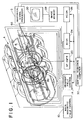
- Figure 1 is a diagrammatic illustration of a magnetic resonance imaging apparatus in accordance with the present invention;
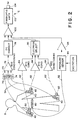
- Figure 2 is a diagrammatic illustration of the cardiac, respiratory, and electrode temperature monitoring apparatus of Figure 1;
- Figure 3 illustrates an electrode chip temperature sensor, and induced current blocking circuit;
- Figure 4 illustrates one embodiment of the induced current blocking array of Figure 2;
- Figure 5 is a diagrammatic illustration of a cardiac, temperature, and respiratory signal processing apparatus of Figure 1;
- Figure 6 is an alternate embodiment in which the cardiac, temperature, and respiratory signals are transmitted digitally along the optic path;
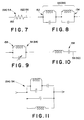
- Figure 7 is an alternate embodiment of the induced current blocking array of Figure 4 in which the impedances are series resistors;
- Figure 8 is an alternate embodiment of the induced current blocking array of Figure 4 which includes multiple, parallel resonant modes in series with the ECG leads;
- Figure 9 is another alternate embodiment of the induced current blocking array of Figure 4 which includes a tuneable, parallel LC circuit in series with the ECG lead;
- Figure 10 is another alternate embodiment of the induced current blocking array of Figure 4 which includes a series resonant circuit in series with the ECG lead; and,
- Figure 11 is another alternate embodiment of the induced current blocking array with combined series and parallel resonant LC circuits.
- With reference to Figure 1, a non-invasive examination apparatus A, such as a magnetic resonance imaging apparatus, receives a subject, particularly a patient B who is to undergo a non-invasive examination. A monitoring means C is disposed adjacent the subject and interconnected with a remote condition signal processing means D. The monitoring means monitors preselected conditions, such as cardiac, respiratory or other anatomical cycles of the patient, the temperature of the patient or of associated equipment such as ECG electrodes, and other system or anatomical conditions. An output signal from the monitoring means C conveys monitored condition information to the processing means D. The processing means D derives monitored condition information from the received data. Optionally, the information is conveyed to the magnetic resonance imaging apparatus A for use in controlling timing of the imaging sequence, the processing of collected data, the collection or filtering of magnetic resonance data, and the like.
- The magnetic resonance imaging apparatus includes a main
magnetic field controller 10 which controls resistive or superconducting mainmagnetic field coils 12 to generate a substantially uniform magnetic field longitudinally through an imaging region. A magnetic field gradient control means 14 applies appropriate current pulses togradient field coils 16 to create gradients across the main magnetic field. The exact nature and sequence of the gradients is determined by which of the many magnetic imaging sequences is chosen. Aradio frequency transmitter 20 generates magnetic resonance excitation, inversion, and manipulation pulses which are applied to aradio frequency coil 22. The gradient and radio frequency pulse sequences are conventional in the art. Aradio frequency receiver 24 receives radio frequency magnetic resonance signals from the subject in the examination region. The resonance signals may be picked up by theradio frequency coil 22 or by localized reception coils (not shown). A reconstruction means 25 utilizes a two dimensional inverse Fourier transform or other known algorithm to construct an electronic image representation from the received magnetic resonance signals. Generally, each echo or other signal is reconstructed into one view, which views are summed into animage memory 28. Completed images in the image memory may be displayed on avideo display monitor 30, subject to further processing, or archived on tape or disk. - A magnetic resonance sequence control means 32 controls the timing with which the gradient field control means and the radio frequency transmitter apply gradient and radio frequency pulses in order to implement one of the conventional magnetic resonance imaging sequences. The timing or spacing between repetitions of the pulse sequence may be adjusted such that each sequence is taken within a preselected range of anatomical motion. Alternately, the
radio frequency receiver 24 or the reconstruction means 26 may be controlled to discard data taken during inappropriate ranges of anatomical movement, to subject such data to heavier filtering, to replace such data with the average of adjoining views, or the like. - With reference to FIGURES 2 and 3, the patient monitor means C includes a first condition detector, in the preferred
embodiment ECG electrodes 40 for monitoring the patient's cardiac cycle. Each electrode includes an electrically conductive surface orfilm 42 and an electrically conductive gel impregnated sponge orfoam 44 for establishing electrical contact with the patient. An adhesive surfacedperipheral flange 46 secures the electrode firmly to the patient. The electricallyconductive surface 42 is electrically connected with a detent or plug means 48 which is selectively snapped into and out of aconnector 50. - The
connector 50 includes an electricallyconductive socket 52 which receives and engages the detent orplug 48. Preferably, thesocket 52 has a series of electrically conductive spring members which engage and resiliently hold an enlargement on theplug member 48. Thesocket 52 is connected with an inducedcurrent blocking impedance 54. Cardiac signals are conveyed through the electrically conductive gel of thesponge 44, the electricallyconductive surface 42, theplug 48, thesocket 52, theimpedance 54, and anECG lead 56. - A temperature sensing means 60, such as a resistive temperature device (RTD) or a thermistor, monitors the temperature of the
socket 52. Because thesocket 52 is in intimate thermal contact with theplug 48 and the electricallyconductive surface 42, the temperature sensor means 60 provides an output indicative of the temperature of theelectrode 40. The temperature sensing means is connected with a temperaturesignal carrying lead 62. In the preferred resistive temperature device, a DC voltage is applied across theECG lead 56 which is also connected to one end of theresistive temperature device 60 and thetemperature sensor lead 62 to monitor temperature dependent changes in the resistance of the resistive temperature device. - Other temperature sensors are also contemplated. In another embodiment, the temperature sensing means 60 is a fluoroptic temperature sensor. The fluoroptic temperature sensor includes an optic fiber that has a phosphor on the end surface thereof whose fluorescence varies as a known function of temperature. In this manner, the light carried on optical
fiber temperature lead 62 is indicative of socket, hence electrode, temperature. - The electrical
temperature sensing device 60 is connected with thetemperature output lead 62 with a second impedance means 64. The second impedance means 64 is of similar construction to the impedance means 54 to prevent currents induced in the temperature output lead 62 from reaching the socket through the resistive temperature device and cause heating of the electrode. - With reference to FIGURE 4, the impedance means 54 and 64 are selected to pass cardiac and temperature signals respectively with essentially no degradation, but to block the passage of electrical currents induced in the
leads connected inductor 66 andcapacitor 68 are connected in series with the electrically conductive lead 56 (62). The inductive and capacitive elements are selected such that they pass cardiac and temperature signals in the range of about 0-150 Hz substantially unattenuated, i.e. the LC circuit is substantially invisible to the cardiac signals. Yet, the components are selected to block currents induced by the radio frequency pulses of the imaging sequence in the MHz range. That is, the filter appears as a very large impedance or open circuit to the high frequency induced currents. Optionally, aresistor 70 is connected in parallel with theinductor 66 andcapacitor 68 to lower the Q or quality factor of the circuit to broaden the frequency band in which the circuit appears as an open circuit or very high impedance. - With reference again to FIGURE 2, a
protection circuit 72 is connected in series with each lead to protect the downstream electronics from induced currents. Theprotection circuit 72 includes animpedance 74 in series with each electrical lead, which impedance is preferably of an analogous construction to impedances 54 and 64. Anamplifier 76 adjusts the magnitude of the cardiac signals. Although theimpedances 74 are selected to block radio frequency induced currents, a slew rate limiting means may be provided to remove other frequency components that are not commonly found in cardiac signals. A DC correction means 78 removes DC offset. - The electrical temperature sensor output leads 62 are connected with a protection circuit having impedances or filters 82 which are again analogous to
impedances - A respiratory monitor, such as an air-filled
elastomeric belt 90 expands and contracts with the patient's breathing. The expansion and contraction causes corresponding changes in air pressure in atube 92. Apressure sensor 94 converts the changes in air pressure communicated bytube 92 into electrical signals indicative of the patient's respiratory cycle. A typical pressure sensor is a balanced bridge pressure to electrical signal transducer that has a bridge circuit across which an oscillator applies a carrier signal, e.g. 2 KHz. The carrier signal modulates the respiratory signal to create an output signal in a frequency range that is readily separated from the cardiac and temperature signals. A beat pattern or amplitude variation of the modulated signal carries the encoded respiratory cycle data. Anamplifier 96 amplifies the respiratory signal. Optionally, a bandpass filter may remove noise and distortion components. - Because the cardiac, temperature, and respiratory signals are all at distinctly different and identifiable frequencies, all are summed by a summing
amplifier 100 to form a composite, analog signal. The composite analog output from the summing means is converted to an output optical signal by an analogfiberoptic transmitter 102. The frequency of the light signals from the transmitter is modulated in proportion to the magnitude of the voltage of the output signal from the summing amplifier and conveyed along anoptic transmission path 104, such as an optic fiber or laser beam. - With reference to FIGURE 5, a
fiberoptic receiver 110 receives the light cardiac, temperature, and respiratory signals and converts them to corresponding electrical signals. The electrical signals from thefiberoptic receiver 110 are conveyed tobandpass filters bandpass filter 112 is a low pass filter which passes low frequency signals, e.g. signals between 10 and 150 Hz. A DC correction means 118 performs a DC correction on the signals passed by thelow pass filter 112. An analog R-wave detecting means 120 detects the R-wave of these signals. - The bandpass filter 114 passes signals with a frequency below about 1 Hz, i.e. the electrode temperature signal. The temperature limit means 122 compares the temperature signal with the preselected temperature. Optionally, a temperature rate of change determining means 124 monitors the rate of change of the temperature. A temperature projecting means 126 determines the rate at which the temperature is approaching the preselected temperature limit. In response to the temperature exceeding the limit temperature or in response to the temperature approaching the limit temperature to within preselected tolerances at greater than a preselected rate, a temperature alarm is sounded. The alarm may be merely a verbal or visual warning or may be a signal to the
central sequence computer 32 which terminates the scan sequence. - The
bandpass filter 116 passes signals with a frequency about 2 KHz, i.e. the respiratory signals. Ademodulation circuit 130 demodulates the respiratory signal from the 2 KHz carrier. Arespiratory detector 132 receives the respiratory signals and provides respiratory status signals to the central sequence computer means 32. This enables the central sequence computer to trigger a scan only at appropriate phases of the respiratory and cardiac cycles and when the temperatures of the electrodes are within appropriate ranges. - The DC correction means 118, the low pass filter 114, and the demodulation means 130 are connected with an analog to
digital converter 134 for digitizing the cardiac, temperature, and respiratory information for convenient computer interface. - With reference to FIGURE 6, the cardiac, temperature, respiratory, and any other monitored conditions can be encoded and transmitted digitally. The analog cardiac, temperature, respiratory, and any other monitored condition signals are communicated to a multiplexing or selecting
means 140. The multiplexing means is clocked at a high frequency to connect each of the cardiac, temperature, respiratory, and other condition signals cyclically with an analog todigital convertor 142. The digital output signals are transmitted by a digital,fiberoptic transmitter 102 along thefiberoptic output cable 104. The clocking rate of the multiplexer is selected in accordance with the speed of the analog to digital convertor and the digital fiberoptic transmitter. Of course, the multiplexer or selectingmeans 140 need not cause the signals to be digitized in cyclic order. Rather, the more rapidly changing signals, such as the cardiac signal, may be connected more frequently with the analog to digital convertor than the slower changing signals such as the temperature and respiratory signals. - The digital optical signals on the
fiberoptic transmission line 104 are received by thefiberoptic receiver 110. The digital signals are transmitted to a sorting means 144 which separates the portions of the digital signal attributable to the cardiac signal, the temperature signal, the respiratory signal, and other condition signals from each other. The cardiac signals are communicated to the R-wave detecting means 120 which issues a trigger signal to thecentral sequence computer 32 in response to each detected R-wave. The R-wave detecting means 120 may operate directly on the digital cardiac signal. Alternately, a digital to analog converting means may convert the cardiac signal to analog form prior to detection of the R-wave. - The sorting means 144 sends the digital temperature signal to the temperature limit checking means 122-126 which compares the received temperature signal with the preselected limits.
- The sorting means 144 sends the digital respiratory signals to the
respiratory detection circuit 132 that monitors the status of the respiratory cycle. Preferably, the digital respiratory signals are not modulated with a higher frequency signal eliminating the need to demodulate the signal. - With reference to FIGURE 7, the impedance or filter
arrays resistor 150, e.g. a 10 K-ohm resistor, in series with the ead. The resistor shunts RF flowing from the ECG leads to the ECG electrodes. The resistor is selected to have a low capacitance and a large impedance to limit RF current flowing from the leads to the ECG electrodes. - With reference to FIGURE 8, each of the arrays may include parallel resonance circuits with multiple resonance modes. A first
LC resonance circuit 152 and a secondLC resonance circuit 154 have inductors and capacitances selected to cover two or more frequencies. This enables the same leads to be used with magnetic resonance apparatus haying different field strengths or operating frequencies. - Alternately, as shown in FIGURE 9, an
LC filter circuit 156 may have a variable capacitor for selectively tuning the resonance frequency. This enables the impedance to be adjusted for different field strength apparatus or the like. - With reference to Figure 10, a series
resonant LC circuit 158 has inductive and capacitive components which pass signals in the ECG frequency range but which attenuate signals of higher frequencies. - With reference to Figure 11, the impedance array may include a combination of parallel and series resonant circuits to provide two modes of operation. The series mode provides a low impedance for the ECG signal, whereas the parallel mode provides a high impedance at RF frequencies.
- Although this description describes a temperature sensing system for cardiac monitoring electrodes, it will be appreciated that such systems could be used to sense the temperature of any electrode.
Claims (14)
- A non-invasive examination apparatus (A) comprising: means for non-invasively examining an internal region of a subject (B) in an examination region with radio frequency energy; monitoring means (C) for monitoring a condition of the subject (B), the monitoring means (C) including at least one electrically conductive monitor lead (56) connected to an electrode (40) which is mounted in contact with the subject (B) and produces monitored condition signals representative of said condition characterised in that said apparatus comprises temperature sensing means (60) for sensing a temperature of the electrode (40).
- An apparatus according to Claim 1 further including bandpass filter means (54) for passing monitored condition signals and blocking the passage of radio frequency currents induced in the monitor lead (56).
- An apparatus according to Claim 2 wherein the bandpass circuit passes signals below 150 Hz substantially unattenuated and presents a high, blocking impedance to radio frequency currents.
- An apparatus according to Claim 2 or 3 further including a resistor (70) connected in parallel with the bandpass circuit for broadening the range of frequencies to which a high impedance is presented.
- An apparatus according to Claim 2, 3 or 4 further including a second bandpass circuit (154) connected in series with the first bandpass circuit (152), the first and second bandpass circuits (152, 154) having different resonance frequencies such that radio frequency signals of at least two frequency bands are blocked.
- An apparatus according to any preceding claim wherein the temperature sensing means (60) includes a temperature sensor (60) and a temperature sensor lead (62) extending from the temperature sensor (60) to a temperature signal output means.
- An apparatus according to Claim 6 wherein the temperature sensor (60) is a fluoroptic sensor which generates light that changes in accordance with temperature and wherein the temperature sensor lead (62) is an optic fiber.
- An apparatus according to Claim 6 wherein the temperature sensing means (60) is an electrical sensor and the temperature sensor lead (62) is an electrically conductive lead and further including a filter means (54, 64) connected with at least one of the temperature sensor lead (62) and the monitor lead (56) for blocking the passage of radio frequency signals therethrough and passing temperature signals.
- An apparatus according to any preceding claim wherein the monitor lead (56) has a socket (52) at one end thereof, the temperature sensing means (60) being mounted in the socket (52) and wherein the electrode (40) has plug means (48) which is releasably received in and electrically connected to the socket (52).
- An apparatus according to Claim 8 or 9 further including: optical signal receiving means (110) for receiving the digital optical signals transmitted along the optical transmission path (104); sorting means (144) for sorting bits of the received digital signal between a monitored condition signal detector (120) and temperature limit checking means (122) for comparing the monitored temperature with a preselected limit.
- An apparatus according to any preceding claim further including: an analog to digital converter (142) operatively connected with the electrical lead for converting the monitored condition signals conveyed along the lead (56) to electrical digital signals; and electro-optical converter means for converting the electrical digital signals to optical digital signals and transmitting the optical digital signals along a light path.
- An apparatus according to Claim 11 further including: multiplexing means (140) for alternately supplying an electrical temperature signal and a monitored condition signal to the analog to digital converter (142).
- A method of non-invasive examination comprising: attaching an electrode (40) which is connected to an electrical lead (56) to a subject (B) and positioning a portion of the subject (B) to be examined in an examination region; subjecting the examination region to changing magnetic fields and radio frequency signals in order to induce magnetic resonance of selected nuclei in the examination region, the radio frequency signals inducing radio frequency currents in the electrical lead (56); receiving magnetic resonance signals from the examination region; and, processing the received magnetic resonance signals into diagnostic information characterised in that the process further includes monitoring a temperature or rate of change of temperature of the electrode (40) and, in response to the monitored electrode temperature or rate of change of temperature exceeding a preselected limit, controlling radio frequency signals to which said region is subjected.
- A method according to Claim 13 further including connecting said electrode (40) to said lead (56) via filter means (54) for blocking passage of radio frequency currents induced in the lead (56) and passing magnetic resonance signals from said electrode (40) to said lead (56).
Applications Claiming Priority (2)
| Application Number | Priority Date | Filing Date | Title |
|---|---|---|---|
| US653628 | 1991-02-11 | ||
| US07/653,628 US5209233A (en) | 1985-08-09 | 1991-02-11 | Temperature sensing and control system for cardiac monitoring electrodes |
Publications (2)
| Publication Number | Publication Date |
|---|---|
| EP0498996A1 true EP0498996A1 (en) | 1992-08-19 |
| EP0498996B1 EP0498996B1 (en) | 1997-03-05 |
Family
ID=24621671
Family Applications (1)
| Application Number | Title | Priority Date | Filing Date |
|---|---|---|---|
| EP91311648A Expired - Lifetime EP0498996B1 (en) | 1991-02-11 | 1991-12-16 | Apparatus and methods for non-invasive examination |
Country Status (4)
| Country | Link |
|---|---|
| US (1) | US5209233A (en) |
| EP (1) | EP0498996B1 (en) |
| JP (1) | JP3312279B2 (en) |
| DE (1) | DE69124982T2 (en) |
Cited By (21)
| Publication number | Priority date | Publication date | Assignee | Title |
|---|---|---|---|---|
| WO1994023648A1 (en) * | 1993-04-22 | 1994-10-27 | 'o.D.A.M.' Office De Distribution D'appareils Medicaux S.A. | Sensor device for electrocardiogram |
| EP0644435A1 (en) * | 1993-09-21 | 1995-03-22 | Gec-Marconi Limited | Magnetic resonance apparatus |
| EP0721110A1 (en) * | 1995-01-09 | 1996-07-10 | O.D.A.M. - OFFICE DE DISTRIBUTION D'APPAREILS MEDICAUX, Société Anonyme | Sensor especially to deliver a signal representative of the respiration of a patient |
| EP1535291A1 (en) * | 2002-09-04 | 2005-06-01 | Draeger Medical Systems, Inc. | An ekg wiring system |
| WO2006008665A1 (en) * | 2004-07-15 | 2006-01-26 | Koninklijke Philips Electronics, N.V. | Wireless mr receiving coil system |
| DE102004037756A1 (en) * | 2004-08-04 | 2006-02-23 | Afs Entwicklungs + Vertriebs Gmbh | Arrangement and method for generating a corona discharge |
| WO2006099010A1 (en) * | 2005-03-09 | 2006-09-21 | Invivo Corporation | Patient supported in-bore monitor for mri |
| EP1773191A2 (en) * | 2004-07-23 | 2007-04-18 | Medrad, Inc. | Wireless patient monitoring device for magnetic resonance imaging |
| US8108042B1 (en) | 2006-11-09 | 2012-01-31 | Greatbatch Ltd. | Capacitor and inductor elements physically disposed in series whose lumped parameters are electrically connected in parallel to form a bandstop filter |
| US8200328B2 (en) | 2005-11-11 | 2012-06-12 | Greatbatch Ltd. | Tank filters placed in series with the lead wires or circuits of active medical devices to enhance MRI compatibility |
| US8649857B2 (en) | 2006-06-08 | 2014-02-11 | Greatbatch Ltd. | Tank filters placed in series with the lead wires or circuits of active medical devices to enhance MRI compatibility |
| USRE46699E1 (en) | 2013-01-16 | 2018-02-06 | Greatbatch Ltd. | Low impedance oxide resistant grounded capacitor for an AIMD |
| US9931514B2 (en) | 2013-06-30 | 2018-04-03 | Greatbatch Ltd. | Low impedance oxide resistant grounded capacitor for an AIMD |
| US10271736B2 (en) | 2014-04-15 | 2019-04-30 | Koninklijke Philips N.V. | Low cost magnetic resonance safe probe for temperature measurement |
| US10350421B2 (en) | 2013-06-30 | 2019-07-16 | Greatbatch Ltd. | Metallurgically bonded gold pocket pad for grounding an EMI filter to a hermetic terminal for an active implantable medical device |
| US10559409B2 (en) | 2017-01-06 | 2020-02-11 | Greatbatch Ltd. | Process for manufacturing a leadless feedthrough for an active implantable medical device |
| US10561837B2 (en) | 2011-03-01 | 2020-02-18 | Greatbatch Ltd. | Low equivalent series resistance RF filter for an active implantable medical device utilizing a ceramic reinforced metal composite filled via |
| US10589107B2 (en) | 2016-11-08 | 2020-03-17 | Greatbatch Ltd. | Circuit board mounted filtered feedthrough assembly having a composite conductive lead for an AIMD |
| US10905888B2 (en) | 2018-03-22 | 2021-02-02 | Greatbatch Ltd. | Electrical connection for an AIMD EMI filter utilizing an anisotropic conductive layer |
| US10912945B2 (en) | 2018-03-22 | 2021-02-09 | Greatbatch Ltd. | Hermetic terminal for an active implantable medical device having a feedthrough capacitor partially overhanging a ferrule for high effective capacitance area |
| US11198014B2 (en) | 2011-03-01 | 2021-12-14 | Greatbatch Ltd. | Hermetically sealed filtered feedthrough assembly having a capacitor with an oxide resistant electrical connection to an active implantable medical device housing |
Families Citing this family (84)
| Publication number | Priority date | Publication date | Assignee | Title |
|---|---|---|---|---|
| US5469847A (en) * | 1992-09-09 | 1995-11-28 | Izi Corporation | Radiographic multi-modality skin markers |
| US5733247A (en) * | 1995-12-20 | 1998-03-31 | Hewlett-Packard Company | MR compatible patient monitor |
| US5730134A (en) * | 1996-09-09 | 1998-03-24 | General Electric Company | System to monitor temperature near an invasive device during magnetic resonance procedures |
| US6073039A (en) * | 1997-11-07 | 2000-06-06 | The United States Of America As Represented By The Department Of Health And Human Services | Device and method for real-time monitoring of an electrocardiogram during magnetic resonance imaging |
| US6032063A (en) * | 1997-12-09 | 2000-02-29 | Vital Connections, Inc. | Distributed resistance leadwire harness assembly for physiological monitoring during magnetic resonance imaging |
| US6701176B1 (en) | 1998-11-04 | 2004-03-02 | Johns Hopkins University School Of Medicine | Magnetic-resonance-guided imaging, electrophysiology, and ablation |
| US8244370B2 (en) * | 2001-04-13 | 2012-08-14 | Greatbatch Ltd. | Band stop filter employing a capacitor and an inductor tank circuit to enhance MRI compatibility of active medical devices |
| US9061139B2 (en) * | 1998-11-04 | 2015-06-23 | Greatbatch Ltd. | Implantable lead with a band stop filter having a capacitor in parallel with an inductor embedded in a dielectric body |
| US6798206B2 (en) | 1998-11-25 | 2004-09-28 | Medrad, Inc. | Neurovascular coil system and interface and system therefor and method of operating same in a multitude of modes |
| US6356081B1 (en) | 1998-11-25 | 2002-03-12 | Medrad, Inc. | Multimode operation of quadrature phased array MR coil systems |
| US6344745B1 (en) | 1998-11-25 | 2002-02-05 | Medrad, Inc. | Tapered birdcage resonator for improved homogeneity in MRI |
| DE19930879C1 (en) * | 1999-07-05 | 2001-02-08 | Siemens Ag | Method of suppressing stimulations in living object during magnetic resonance tomography |
| US6914529B2 (en) * | 1999-07-21 | 2005-07-05 | Dow Agrosciences Llc | Sensing devices, systems, and methods particularly for pest control |
| US7348890B2 (en) * | 1999-07-21 | 2008-03-25 | Dow Agrosciences Llc | Pest control techniques |
| DE69924125D1 (en) * | 1999-07-21 | 2005-04-14 | Dow Agrosciences Llc | PEST CONTROL METHODS |
| US7212129B2 (en) | 1999-07-21 | 2007-05-01 | Dow Agrosciences Llc | Devices, systems, and method to control pests |
| US6724312B1 (en) | 1999-07-21 | 2004-04-20 | Daniel Barber | Pest control apparatus and methods |
| US7212112B2 (en) * | 1999-07-21 | 2007-05-01 | Dow Agrosciences Llc | Detection and control of pests |
| US7262702B2 (en) * | 1999-07-21 | 2007-08-28 | Dow Agrosciences Llc | Pest control devices, systems, and methods |
| US6270463B1 (en) | 1999-11-23 | 2001-08-07 | Medrad, Inc. | System and method for measuring temperature in a strong electromagnetic field |
| US8527046B2 (en) * | 2000-04-20 | 2013-09-03 | Medtronic, Inc. | MRI-compatible implantable device |
| DE10047365B4 (en) * | 2000-09-25 | 2005-07-28 | Siemens Ag | Physiological sensor system |
| WO2002062219A1 (en) * | 2001-02-06 | 2002-08-15 | Koninklijke Philips Electronics N.V. | Medical examination apparatus, notably a magnetic resonance examination apparatus |
| US8509913B2 (en) * | 2001-04-13 | 2013-08-13 | Greatbatch Ltd. | Switched diverter circuits for minimizing heating of an implanted lead and/or providing EMI protection in a high power electromagnetic field environment |
| US8712544B2 (en) | 2001-04-13 | 2014-04-29 | Greatbatch Ltd. | Electromagnetic shield for a passive electronic component in an active medical device implantable lead |
| US9295828B2 (en) | 2001-04-13 | 2016-03-29 | Greatbatch Ltd. | Self-resonant inductor wound portion of an implantable lead for enhanced MRI compatibility of active implantable medical devices |
| US8977355B2 (en) | 2001-04-13 | 2015-03-10 | Greatbatch Ltd. | EMI filter employing a capacitor and an inductor tank circuit having optimum component values |
| US8219208B2 (en) | 2001-04-13 | 2012-07-10 | Greatbatch Ltd. | Frequency selective passive component networks for active implantable medical devices utilizing an energy dissipating surface |
| US8155760B2 (en) * | 2001-04-13 | 2012-04-10 | Greatbatch Ltd. | Medical lead system utilizing electromagnetic bandstop filters |
| US7853325B2 (en) * | 2001-04-13 | 2010-12-14 | Greatbatch Ltd. | Cylindrical bandstop filters for medical lead systems |
| US8457760B2 (en) | 2001-04-13 | 2013-06-04 | Greatbatch Ltd. | Switched diverter circuits for minimizing heating of an implanted lead and/or providing EMI protection in a high power electromagnetic field environment |
| US8989870B2 (en) * | 2001-04-13 | 2015-03-24 | Greatbatch Ltd. | Tuned energy balanced system for minimizing heating and/or to provide EMI protection of implanted leads in a high power electromagnetic field environment |
| US7899551B2 (en) * | 2001-04-13 | 2011-03-01 | Greatbatch Ltd. | Medical lead system utilizing electromagnetic bandstop filters |
| US20070088416A1 (en) * | 2001-04-13 | 2007-04-19 | Surgi-Vision, Inc. | Mri compatible medical leads |
| US7787958B2 (en) * | 2001-04-13 | 2010-08-31 | Greatbatch Ltd. | RFID detection and identification system for implantable medical lead systems |
| CA2482202C (en) | 2001-04-13 | 2012-07-03 | Surgi-Vision, Inc. | Systems and methods for magnetic-resonance-guided interventional procedures |
| US7039455B1 (en) | 2001-10-09 | 2006-05-02 | Medrad, Inc. | Apparatus and method for removing magnetic resonance imaging-induced noise from ECG signals |
| WO2003039337A2 (en) * | 2001-11-02 | 2003-05-15 | Henry M. Jackson Foundation | Cardiac gating method and system |
| EP1508051A1 (en) | 2002-05-29 | 2005-02-23 | Surgi-Vision, Inc. | Magnetic resonance probes |
| JP3643573B2 (en) * | 2002-06-05 | 2005-04-27 | 安西メディカル株式会社 | Radiation irradiation synchronization signal generator |
| US7084629B2 (en) | 2002-11-27 | 2006-08-01 | Medrad, Inc. | Parallel imaging compatible birdcage resonator |
| US20040225210A1 (en) * | 2003-01-31 | 2004-11-11 | Brosovich John A. | Electrode lead-set for use with bioelectric signal detection/acquisition devices |
| US7519413B1 (en) | 2003-02-20 | 2009-04-14 | S.A. Instruments, Inc. | Apparatus and method for measuring motion in a strong magnetic field |
| US20050283213A1 (en) * | 2003-08-25 | 2005-12-22 | Biophan Technologies, Inc. | Medical device with an electrically conductive anti-antenna member |
| US20090012387A1 (en) * | 2004-05-25 | 2009-01-08 | Hvidovre Hospital | Encoding and transmission of signals as rf signals for detection using an mr apparatus |
| US7226447B2 (en) * | 2004-06-23 | 2007-06-05 | Smith & Nephew, Inc. | Electrosurgical generator |
| US8874228B2 (en) * | 2004-07-27 | 2014-10-28 | The Cleveland Clinic Foundation | Integrated system and method for MRI-safe implantable devices |
| DE102004037375A1 (en) * | 2004-08-02 | 2006-03-30 | Siemens Ag | Physiological sensor system |
| US7655003B2 (en) | 2005-06-22 | 2010-02-02 | Smith & Nephew, Inc. | Electrosurgical power control |
| JP2009511105A (en) * | 2005-10-06 | 2009-03-19 | コーニンクレッカ フィリップス エレクトロニクス エヌ ヴィ | Cable-free MR coil |
| US8224462B2 (en) | 2005-11-11 | 2012-07-17 | Greatbatch Ltd. | Medical lead system utilizing electromagnetic bandstop filters |
| EP2392382A1 (en) * | 2005-11-11 | 2011-12-07 | Greatbatch Ltd. | Tank filters placed in series with the lead wires or circuits of active medical devices to enhance MRI compatibility |
| US9042999B2 (en) * | 2006-06-08 | 2015-05-26 | Greatbatch Ltd. | Low loss band pass filter for RF distance telemetry pin antennas of active implantable medical devices |
| US7702387B2 (en) * | 2006-06-08 | 2010-04-20 | Greatbatch Ltd. | Tank filters adaptable for placement with a guide wire, in series with the lead wires or circuits of active medical devices to enhance MRI compatibility |
| US8903505B2 (en) * | 2006-06-08 | 2014-12-02 | Greatbatch Ltd. | Implantable lead bandstop filter employing an inductive coil with parasitic capacitance to enhance MRI compatibility of active medical devices |
| US9031670B2 (en) | 2006-11-09 | 2015-05-12 | Greatbatch Ltd. | Electromagnetic shield for a passive electronic component in an active medical device implantable lead |
| US9468750B2 (en) | 2006-11-09 | 2016-10-18 | Greatbatch Ltd. | Multilayer planar spiral inductor filter for medical therapeutic or diagnostic applications |
| US7671750B2 (en) * | 2006-12-19 | 2010-03-02 | Dow Agrosciences Llc | High reliability pest detection |
| CN101621923B (en) | 2006-12-21 | 2013-09-18 | 美国陶氏益农公司 | Composite material including a thermoplastic polymer, a pest food material and a pesticide |
| US7711436B2 (en) * | 2007-03-09 | 2010-05-04 | Medtronic, Inc. | Medical device electrical lead design for preventing transmittance of unsafe currents to a patient |
| US9108066B2 (en) | 2008-03-20 | 2015-08-18 | Greatbatch Ltd. | Low impedance oxide resistant grounded capacitor for an AIMD |
| US10080889B2 (en) | 2009-03-19 | 2018-09-25 | Greatbatch Ltd. | Low inductance and low resistance hermetically sealed filtered feedthrough for an AIMD |
| TWI478665B (en) | 2008-08-19 | 2015-04-01 | Dow Agrosciences Llc | Bait materials, pest monitoring devices and other pest control devices that include polyurethane foam |
| US8447414B2 (en) * | 2008-12-17 | 2013-05-21 | Greatbatch Ltd. | Switched safety protection circuit for an AIMD system during exposure to high power electromagnetic fields |
| US8996126B2 (en) | 2009-02-04 | 2015-03-31 | Greatbatch Ltd. | Composite RF current attenuator for a medical lead |
| US20100217115A1 (en) * | 2009-02-25 | 2010-08-26 | Hushek Stephen G | Temperature sensing within a patient during mr imaging |
| US8855788B2 (en) | 2009-03-04 | 2014-10-07 | Imricor Medical Systems, Inc. | MRI compatible electrode circuit |
| US8805540B2 (en) | 2009-03-04 | 2014-08-12 | Imricor Medical Systems, Inc. | MRI compatible cable |
| CA2754045C (en) | 2009-03-04 | 2021-04-06 | Imricor Medical Systems, Inc. | Mri compatible electrode circuit |
| US8761899B2 (en) | 2009-03-04 | 2014-06-24 | Imricor Medical Systems, Inc. | MRI compatible conductive wires |
| US8843213B2 (en) | 2009-03-04 | 2014-09-23 | Imricor Medical Systems, Inc. | MRI compatible co-radially wound lead assembly |
| US8831743B2 (en) | 2009-03-04 | 2014-09-09 | Imricor Medical Systems, Inc. | MRI compatible electrode circuit |
| DE102009001984A1 (en) * | 2009-03-30 | 2010-10-14 | Bruker Biospin Ag | Device for monitoring a living being during a magnetic resonance experiment |
| EP2440130A4 (en) | 2009-06-08 | 2015-06-03 | Mri Interventions Inc | Mri-guided surgical systems with proximity alerts |
| US8396532B2 (en) | 2009-06-16 | 2013-03-12 | MRI Interventions, Inc. | MRI-guided devices and MRI-guided interventional systems that can track and generate dynamic visualizations of the devices in near real time |
| US9919158B2 (en) * | 2009-12-29 | 2018-03-20 | Medtronic, Inc. | Configuring operating parameters of a medical device based on exposure to a disruptive energy field |
| EP2596376B1 (en) * | 2010-07-23 | 2017-05-03 | Koninklijke Philips N.V. | Dual pressure sensor signal chain to remove mutually-coupled mri interference |
| US9427596B2 (en) | 2013-01-16 | 2016-08-30 | Greatbatch Ltd. | Low impedance oxide resistant grounded capacitor for an AIMD |
| DE202011104334U1 (en) * | 2011-08-12 | 2012-11-21 | Brain Products Gmbh | EEG electrode with an indicator for improving the safety of EEG recordings, in particular during a scan by means of an imaging method |
| US20150015254A1 (en) | 2013-05-17 | 2015-01-15 | Imris Inc. | Control of SAR Values in MR Imaging |
| US20170000374A1 (en) * | 2013-12-11 | 2017-01-05 | Koninklijke Philips N.V. | Planar magnetic resonance safe cable for biopotential measurements |
| DE102014006999A1 (en) * | 2014-05-13 | 2015-11-19 | Swissmed Mobile Ag | Device and method for in-vivo acquisition of patient data and transmission to a data processing device |
| CN106291138A (en) * | 2016-08-29 | 2017-01-04 | 武汉中科科理光电技术有限公司 | A kind of medical radio-frequency electric field energy temperature measuring device and method of testing |
| US11550006B2 (en) * | 2018-11-08 | 2023-01-10 | Canon Medical Systems Corporation | Magnetic resonance imaging apparatus |
Citations (4)
| Publication number | Priority date | Publication date | Assignee | Title |
|---|---|---|---|---|
| US4095588A (en) * | 1976-07-19 | 1978-06-20 | Joseph Goldman | Vascular cleansing |
| US4308870A (en) * | 1980-06-04 | 1982-01-05 | The Kendall Company | Vital signs monitor |
| EP0132785A2 (en) * | 1983-08-01 | 1985-02-13 | Siemens Aktiengesellschaft | Electrocardiographic signal transducer applied to a nuclear magnetic resonance tomograph |
| EP0343858A2 (en) * | 1988-05-23 | 1989-11-29 | Zvi Taicher | Remote temperature control monitoring apparatus and technique |
Family Cites Families (4)
| Publication number | Priority date | Publication date | Assignee | Title |
|---|---|---|---|---|
| US3910257A (en) * | 1973-04-25 | 1975-10-07 | Nasa | Medical subject monitoring systems |
| JPS59155239A (en) * | 1983-02-23 | 1984-09-04 | 株式会社東芝 | Diagnostic nuclear magnetic resonance apparatus |
| DE3430625A1 (en) * | 1984-08-20 | 1986-02-27 | Siemens AG, 1000 Berlin und 8000 München | DEVICE FOR THE CORE SPIN TOMOGRAPHY |
| US4951672A (en) * | 1985-07-02 | 1990-08-28 | General Electric Company | Controlled impedance monitoring lead wires |
-
1991
- 1991-02-11 US US07/653,628 patent/US5209233A/en not_active Expired - Lifetime
- 1991-12-16 DE DE69124982T patent/DE69124982T2/en not_active Expired - Fee Related
- 1991-12-16 EP EP91311648A patent/EP0498996B1/en not_active Expired - Lifetime
-
1992
- 1992-01-20 JP JP02891992A patent/JP3312279B2/en not_active Expired - Fee Related
Patent Citations (4)
| Publication number | Priority date | Publication date | Assignee | Title |
|---|---|---|---|---|
| US4095588A (en) * | 1976-07-19 | 1978-06-20 | Joseph Goldman | Vascular cleansing |
| US4308870A (en) * | 1980-06-04 | 1982-01-05 | The Kendall Company | Vital signs monitor |
| EP0132785A2 (en) * | 1983-08-01 | 1985-02-13 | Siemens Aktiengesellschaft | Electrocardiographic signal transducer applied to a nuclear magnetic resonance tomograph |
| EP0343858A2 (en) * | 1988-05-23 | 1989-11-29 | Zvi Taicher | Remote temperature control monitoring apparatus and technique |
Cited By (32)
| Publication number | Priority date | Publication date | Assignee | Title |
|---|---|---|---|---|
| FR2704131A1 (en) * | 1993-04-22 | 1994-10-28 | Odam | Sensor device for electrocardiogram. |
| US5782241A (en) * | 1993-04-22 | 1998-07-21 | O.D.A.M. Office De Distribution D'appareils Medicaux (Sa) | Sensor device for electrocardiogram |
| WO1994023648A1 (en) * | 1993-04-22 | 1994-10-27 | 'o.D.A.M.' Office De Distribution D'appareils Medicaux S.A. | Sensor device for electrocardiogram |
| US5602478A (en) * | 1993-09-21 | 1997-02-11 | Gec-Marconi Limited | Reduction of RF field disturbance in magnetic resonance apparatus |
| EP0644435A1 (en) * | 1993-09-21 | 1995-03-22 | Gec-Marconi Limited | Magnetic resonance apparatus |
| US5691641A (en) * | 1995-01-09 | 1997-11-25 | "O.D.A.M." Office De Distribution D'appareils Medicaux (Societe Anonyme) | NMR pickup device delivering a signal representative of breathing of a patient |
| FR2729071A1 (en) * | 1995-01-09 | 1996-07-12 | Odam Office De Distribution D | SENSOR DEVICE DELIVERING IN PARTICULAR A SIGNAL REPRESENTATIVE OF THE BREATH OF A PATIENT |
| EP0721110A1 (en) * | 1995-01-09 | 1996-07-10 | O.D.A.M. - OFFICE DE DISTRIBUTION D'APPAREILS MEDICAUX, Société Anonyme | Sensor especially to deliver a signal representative of the respiration of a patient |
| EP1535291A1 (en) * | 2002-09-04 | 2005-06-01 | Draeger Medical Systems, Inc. | An ekg wiring system |
| WO2006008665A1 (en) * | 2004-07-15 | 2006-01-26 | Koninklijke Philips Electronics, N.V. | Wireless mr receiving coil system |
| US7443165B2 (en) | 2004-07-15 | 2008-10-28 | Koninklijke Philips Electronics N.V. | Wireless MR receiving coil system |
| EP1773191A2 (en) * | 2004-07-23 | 2007-04-18 | Medrad, Inc. | Wireless patient monitoring device for magnetic resonance imaging |
| EP1773191A4 (en) * | 2004-07-23 | 2009-11-11 | Medrad Inc | Wireless patient monitoring device for magnetic resonance imaging |
| DE102004037756A1 (en) * | 2004-08-04 | 2006-02-23 | Afs Entwicklungs + Vertriebs Gmbh | Arrangement and method for generating a corona discharge |
| WO2006099010A1 (en) * | 2005-03-09 | 2006-09-21 | Invivo Corporation | Patient supported in-bore monitor for mri |
| US8200328B2 (en) | 2005-11-11 | 2012-06-12 | Greatbatch Ltd. | Tank filters placed in series with the lead wires or circuits of active medical devices to enhance MRI compatibility |
| US8463375B2 (en) | 2005-11-11 | 2013-06-11 | Greatbatch Ltd. | Tank filters placed in series with the lead wires or circuits of active medical devices to enhance MRI compatability |
| US8649857B2 (en) | 2006-06-08 | 2014-02-11 | Greatbatch Ltd. | Tank filters placed in series with the lead wires or circuits of active medical devices to enhance MRI compatibility |
| US8108042B1 (en) | 2006-11-09 | 2012-01-31 | Greatbatch Ltd. | Capacitor and inductor elements physically disposed in series whose lumped parameters are electrically connected in parallel to form a bandstop filter |
| US10561837B2 (en) | 2011-03-01 | 2020-02-18 | Greatbatch Ltd. | Low equivalent series resistance RF filter for an active implantable medical device utilizing a ceramic reinforced metal composite filled via |
| US11198014B2 (en) | 2011-03-01 | 2021-12-14 | Greatbatch Ltd. | Hermetically sealed filtered feedthrough assembly having a capacitor with an oxide resistant electrical connection to an active implantable medical device housing |
| US11071858B2 (en) | 2011-03-01 | 2021-07-27 | Greatbatch Ltd. | Hermetically sealed filtered feedthrough having platinum sealed directly to the insulator in a via hole |
| US10596369B2 (en) | 2011-03-01 | 2020-03-24 | Greatbatch Ltd. | Low equivalent series resistance RF filter for an active implantable medical device |
| USRE46699E1 (en) | 2013-01-16 | 2018-02-06 | Greatbatch Ltd. | Low impedance oxide resistant grounded capacitor for an AIMD |
| US9931514B2 (en) | 2013-06-30 | 2018-04-03 | Greatbatch Ltd. | Low impedance oxide resistant grounded capacitor for an AIMD |
| US10350421B2 (en) | 2013-06-30 | 2019-07-16 | Greatbatch Ltd. | Metallurgically bonded gold pocket pad for grounding an EMI filter to a hermetic terminal for an active implantable medical device |
| US10271736B2 (en) | 2014-04-15 | 2019-04-30 | Koninklijke Philips N.V. | Low cost magnetic resonance safe probe for temperature measurement |
| US10589107B2 (en) | 2016-11-08 | 2020-03-17 | Greatbatch Ltd. | Circuit board mounted filtered feedthrough assembly having a composite conductive lead for an AIMD |
| US10559409B2 (en) | 2017-01-06 | 2020-02-11 | Greatbatch Ltd. | Process for manufacturing a leadless feedthrough for an active implantable medical device |
| US10905888B2 (en) | 2018-03-22 | 2021-02-02 | Greatbatch Ltd. | Electrical connection for an AIMD EMI filter utilizing an anisotropic conductive layer |
| US10912945B2 (en) | 2018-03-22 | 2021-02-09 | Greatbatch Ltd. | Hermetic terminal for an active implantable medical device having a feedthrough capacitor partially overhanging a ferrule for high effective capacitance area |
| US11712571B2 (en) | 2018-03-22 | 2023-08-01 | Greatbatch Ltd. | Electrical connection for a hermetic terminal for an active implantable medical device utilizing a ferrule pocket |
Also Published As
| Publication number | Publication date |
|---|---|
| JP3312279B2 (en) | 2002-08-05 |
| JPH0654823A (en) | 1994-03-01 |
| EP0498996B1 (en) | 1997-03-05 |
| DE69124982T2 (en) | 1997-06-12 |
| US5209233A (en) | 1993-05-11 |
| DE69124982D1 (en) | 1997-04-10 |
Similar Documents
| Publication | Publication Date | Title |
|---|---|---|
| US5209233A (en) | Temperature sensing and control system for cardiac monitoring electrodes | |
| EP0429190B1 (en) | Non-invasive examination apparatus and methods | |
| US4694837A (en) | Cardiac and respiratory gated magnetic resonance imaging | |
| US5038785A (en) | Cardiac and respiratory monitor with magnetic gradient noise elimination | |
| TWI308066B (en) | Electrodynamic sensors and applications thereof | |
| EP2596376B1 (en) | Dual pressure sensor signal chain to remove mutually-coupled mri interference | |
| Allen et al. | A method for removing imaging artifact from continuous EEG recorded during functional MRI | |
| US5131399A (en) | Patient monitoring apparatus and method | |
| JP2945480B2 (en) | Electrocardiogram sensor device | |
| US8860504B2 (en) | Method and apparatus for measuring biological signal | |
| EP1273922B1 (en) | Methods and devices for measuring electrical currents | |
| US20010045899A1 (en) | Passive biotelemetry | |
| US20100191095A1 (en) | Process, device and system for reducing the artifacts that affect electrophysiological signals and that are due to electromagnetic fields | |
| EP2155054B1 (en) | Active discharge of electrode | |
| US5052398A (en) | QRS filter for real time heart imaging with ECG monitoring in the magnetic field of an NMR imaging system and NMR imaging apparatus employing such filter | |
| US20050113666A1 (en) | Electroencephalograph sensor for use with magnetic resonance imaging and methods using such arrangements | |
| JP2947151B2 (en) | In particular, a sensor device for transmitting a signal representing the patient's breathing | |
| FI59718B (en) | FOERFARANDE INOM LAEKARVETENSKAPEN FOER OEVERVAKNING OCH / ELLER REGISTRERING AV EN PAO EN SAENG LIGGANDE PERSONS T EX EN PATIENTS KROPPSROERELSER | |
| Goovaerts et al. | A transducer for detection of fetal breathing movements | |
| JP4700209B2 (en) | Passive biotelemetry | |
| Felblinger et al. | Recordings of eye movements for stimulus control during fMRI by means of electro‐oculographic methods | |
| US7519413B1 (en) | Apparatus and method for measuring motion in a strong magnetic field | |
| JPS6125543A (en) | Non-contact measuring apparatus of organ motion | |
| JP2770694B2 (en) | Biological information processing device | |
| KR100983256B1 (en) | Method and system for measuring biopotential signal, and diagnostic system |
Legal Events
| Date | Code | Title | Description |
|---|---|---|---|
| PUAI | Public reference made under article 153(3) epc to a published international application that has entered the european phase |
Free format text: ORIGINAL CODE: 0009012 |
|
| AK | Designated contracting states |
Kind code of ref document: A1 Designated state(s): DE FR NL |
|
| 17P | Request for examination filed |
Effective date: 19920821 |
|
| 17Q | First examination report despatched |
Effective date: 19950727 |
|
| GRAG | Despatch of communication of intention to grant |
Free format text: ORIGINAL CODE: EPIDOS AGRA |
|
| GRAH | Despatch of communication of intention to grant a patent |
Free format text: ORIGINAL CODE: EPIDOS IGRA |
|
| GRAH | Despatch of communication of intention to grant a patent |
Free format text: ORIGINAL CODE: EPIDOS IGRA |
|
| GRAA | (expected) grant |
Free format text: ORIGINAL CODE: 0009210 |
|
| AK | Designated contracting states |
Kind code of ref document: B1 Designated state(s): DE FR NL |
|
| ET | Fr: translation filed | ||
| REF | Corresponds to: |
Ref document number: 69124982 Country of ref document: DE Date of ref document: 19970410 |
|
| ET | Fr: translation filed |
Free format text: CORRECTIONS |
|
| PLBE | No opposition filed within time limit |
Free format text: ORIGINAL CODE: 0009261 |
|
| STAA | Information on the status of an ep patent application or granted ep patent |
Free format text: STATUS: NO OPPOSITION FILED WITHIN TIME LIMIT |
|
| 26N | No opposition filed | ||
| PGFP | Annual fee paid to national office [announced via postgrant information from national office to epo] |
Ref country code: NL Payment date: 20021112 Year of fee payment: 12 |
|
| REG | Reference to a national code |
Ref country code: FR Ref legal event code: CD |
|
| PG25 | Lapsed in a contracting state [announced via postgrant information from national office to epo] |
Ref country code: NL Free format text: LAPSE BECAUSE OF NON-PAYMENT OF DUE FEES Effective date: 20040701 |
|
| REG | Reference to a national code |
Ref country code: FR Ref legal event code: TP |
|
| NLV4 | Nl: lapsed or anulled due to non-payment of the annual fee |
Effective date: 20040701 |
|
| PGFP | Annual fee paid to national office [announced via postgrant information from national office to epo] |
Ref country code: FR Payment date: 20041228 Year of fee payment: 14 |
|
| PGFP | Annual fee paid to national office [announced via postgrant information from national office to epo] |
Ref country code: DE Payment date: 20050215 Year of fee payment: 14 |
|
| PG25 | Lapsed in a contracting state [announced via postgrant information from national office to epo] |
Ref country code: DE Free format text: LAPSE BECAUSE OF NON-PAYMENT OF DUE FEES Effective date: 20060701 |
|
| PG25 | Lapsed in a contracting state [announced via postgrant information from national office to epo] |
Ref country code: FR Free format text: LAPSE BECAUSE OF NON-PAYMENT OF DUE FEES Effective date: 20060831 |
|
| REG | Reference to a national code |
Ref country code: FR Ref legal event code: ST Effective date: 20060831 |