EP0498885B1 - A method of measuring blood pressure with a photoplethysmograph - Google Patents
A method of measuring blood pressure with a photoplethysmograph Download PDFInfo
- Publication number
- EP0498885B1 EP0498885B1 EP91918602A EP91918602A EP0498885B1 EP 0498885 B1 EP0498885 B1 EP 0498885B1 EP 91918602 A EP91918602 A EP 91918602A EP 91918602 A EP91918602 A EP 91918602A EP 0498885 B1 EP0498885 B1 EP 0498885B1
- Authority
- EP
- European Patent Office
- Prior art keywords
- arterial
- during
- photoplethysmograph
- exp
- value
- Prior art date
- Legal status (The legal status is an assumption and is not a legal conclusion. Google has not performed a legal analysis and makes no representation as to the accuracy of the status listed.)
- Expired - Lifetime
Links
- 238000000034 method Methods 0.000 title claims abstract description 53
- 230000036772 blood pressure Effects 0.000 title claims abstract description 24
- 239000008280 blood Substances 0.000 claims abstract description 31
- 210000004369 blood Anatomy 0.000 claims abstract description 31
- 230000035487 diastolic blood pressure Effects 0.000 claims abstract description 31
- 230000035488 systolic blood pressure Effects 0.000 claims abstract description 28
- 230000004872 arterial blood pressure Effects 0.000 claims abstract description 27
- 238000005259 measurement Methods 0.000 claims abstract description 23
- 210000001367 artery Anatomy 0.000 claims description 16
- 230000000747 cardiac effect Effects 0.000 claims description 16
- 230000003205 diastolic effect Effects 0.000 claims description 12
- 230000035485 pulse pressure Effects 0.000 claims description 10
- 238000006243 chemical reaction Methods 0.000 claims description 6
- 230000004882 diastolic arterial blood pressure Effects 0.000 claims 5
- 230000004873 systolic arterial blood pressure Effects 0.000 claims 5
- 238000010586 diagram Methods 0.000 description 8
- 230000006870 function Effects 0.000 description 7
- 238000012544 monitoring process Methods 0.000 description 4
- 230000005540 biological transmission Effects 0.000 description 3
- 238000009530 blood pressure measurement Methods 0.000 description 3
- 238000004364 calculation method Methods 0.000 description 3
- 239000000463 material Substances 0.000 description 3
- 230000008321 arterial blood flow Effects 0.000 description 2
- 230000001419 dependent effect Effects 0.000 description 2
- 230000000694 effects Effects 0.000 description 2
- 238000010521 absorption reaction Methods 0.000 description 1
- 230000009286 beneficial effect Effects 0.000 description 1
- 230000008033 biological extinction Effects 0.000 description 1
- 230000015572 biosynthetic process Effects 0.000 description 1
- 230000017531 blood circulation Effects 0.000 description 1
- 239000002131 composite material Substances 0.000 description 1
- 238000009795 derivation Methods 0.000 description 1
- 238000011161 development Methods 0.000 description 1
- 238000010348 incorporation Methods 0.000 description 1
- 238000013178 mathematical model Methods 0.000 description 1
- 238000012986 modification Methods 0.000 description 1
- 230000004048 modification Effects 0.000 description 1
- 230000036581 peripheral resistance Effects 0.000 description 1
- 238000005070 sampling Methods 0.000 description 1
- 238000001356 surgical procedure Methods 0.000 description 1
- 238000003786 synthesis reaction Methods 0.000 description 1
Images


Classifications
-
- A—HUMAN NECESSITIES
- A61—MEDICAL OR VETERINARY SCIENCE; HYGIENE
- A61B—DIAGNOSIS; SURGERY; IDENTIFICATION
- A61B5/00—Measuring for diagnostic purposes; Identification of persons
- A61B5/02—Detecting, measuring or recording pulse, heart rate, blood pressure or blood flow; Combined pulse/heart-rate/blood pressure determination; Evaluating a cardiovascular condition not otherwise provided for, e.g. using combinations of techniques provided for in this group with electrocardiography or electroauscultation; Heart catheters for measuring blood pressure
- A61B5/024—Detecting, measuring or recording pulse rate or heart rate
- A61B5/02416—Detecting, measuring or recording pulse rate or heart rate using photoplethysmograph signals, e.g. generated by infrared radiation
-
- A—HUMAN NECESSITIES
- A61—MEDICAL OR VETERINARY SCIENCE; HYGIENE
- A61B—DIAGNOSIS; SURGERY; IDENTIFICATION
- A61B5/00—Measuring for diagnostic purposes; Identification of persons
- A61B5/02—Detecting, measuring or recording pulse, heart rate, blood pressure or blood flow; Combined pulse/heart-rate/blood pressure determination; Evaluating a cardiovascular condition not otherwise provided for, e.g. using combinations of techniques provided for in this group with electrocardiography or electroauscultation; Heart catheters for measuring blood pressure
- A61B5/021—Measuring pressure in heart or blood vessels
Definitions
- This invention relates generally to blood pressure measurements. More particularly, it relates to a method of non-invasively determining blood pressure using a photoplethysmograph.
- Arterial blood pressure measurements provide valuable information about a patient's condition.
- the heart's cyclical action produces a blood pressure maximum at systole, called systolic pressure, and a minimum pressure at diastole, called diastolic pressure. While the systolic and diastolic pressures are themselves important in gauging the patient's condition, other useful parameters are the mean (average) blood pressure during a heart cycle, and the pulse pressure, which is the arithmetic difference between the systolic and diastolic pressures.
- the importance of arterial blood pressure has spurred the development of numerous methods of determining it.
- the most widely used method is probably the familiar blood pressure cuff, which consists of an expandable ring (1) inflated to stop arterial blood flow and (2) then gradually contracted.
- a stethoscope medical personnel listen to the artery to determine at what pressure blood flow begins, establishing the systolic pressure, and at what pressure flow is unrestricted, establishing the diastolic pressure.
- More advanced blood pressure monitoring systems plot the arterial blood pressure through a complete heart cycle. Typically, these systems use catheters having piezoelectric pressure transducers that produce output signals dependent upon the instantaneous blood pressure. The output signals are monitored and used to determine the arterial blood pressures over a complete heart cycle. These systems are advantageous in that the blood pressure is continuously measured and displayed.
- Cuff-type systems require restricting arterial blood flow and are not suitable for continuous use.
- the piezoelectric-type systems generally require undesirable invasive techniques, costly disposable materials, and time and skill to set-up.
- continuous arterial blood pressure monitoring is highly desirable. Therefore, it would be beneficial to have a method of continuously and non-invasively measuring a patient's blood pressure.
- Photoplethysmographs are well-known instruments which use light for determining and registering variations in a patient's blood volume. They can instantaneously track arterial blood volume changes during the cardiac cycle. Since photoplethysmographs operate non-invasively, much work has gone into using them to determine blood pressure. In 1983, inventor Warner was issued U.S. Patent No. 4,418,700 on a method of determining circulatory parameters, wherein signals from a photoplethysmograph were used to determine arterial blood pressure.
- a non-invasive method for determining heart-related parameters in patients by means of a photoelectric plethysmograph determines pulse pressure, time constant of the arterial system, systolic and diastolic pressure, peripheral resistance, cardiac output and mean arterial blood pressure.
- the object of the present invention is to provide an improved method for a continuously and non-invasively measuring arterial blood pressure.
- a preferred embodiment of the present invention uses a transmitter 2 portion of a photoplethysmograph 4 to cause monochromatic light 6, preferably in the red and IR ranges, to be emitted from a photodiode light source 8.
- the emitted monochromatic light 6 travels through a patient 9, along a light path which includes blood 10 in an artery 12, to a photodiode light detector 14. While artery 12 has been described, and is shown in Figure 1, as a single artery, in all practical cases the light path actually passes through many arteries. These arteries can be lumped together and treated as if only one artery 12 existed.
- the transmitter 2 controls the amount of monochromatic light 6 emitted by varying the amount of current through the light source 8. In the preferred embodiment, the transmitter 2 regulates the monochromatic light 6 at a fixed level.
- the monochromatic light 6 As the monochromatic light 6 travels along its light path it is partially absorbed by the background tissue 16 and the blood 10. A portion of the monochromatic light 6 is not absorbed and impinges on the light detector 14, creating electrical signals which are applied to a receiver 18 of the photoplethysmograph 4. The magnitudes of these electrical signals depend upon the amount of monochromatic light emitted by the light source 8, the path lengths through the background tissue 16 and the blood 10, the amount of light absorbed per unit length by the blood 10 and tissue 16, the conversion efficiency of the light detector 14, and various lumped losses such as poor focusing of the monochromatic light 6.
- the artery 12 Since the artery 12 is pliant, as blood pressure increase so does the volume of blood 10 within the artery 12. As the heart beats, its cyclical action causes the arterial blood pressure to change. This causes the electrical signals to change since the path length through the blood 10 changes, causing the amount of monochromatic light 6 absorbed by the blood 10 to change. Therefore, the electrical signals from the light detector 14 applied to the receiver 18 is a function of the arterial blood pressure.
- the receiver 18 amplifies the electrical signals to a usable level and applies them as analog signals, via a receiver line 22, to an analog-to-digital converter A/D 23.
- the A/D 23 converts the outputs of the receiver 18 to time sampled digital signals which are applied to the computer 24 via a computer bus 25.
- the signals on the receiver line 22 can be represented by the photoplethysmograph output waveform 26, shown in Figure 2 for two cardiac cycles.
- the horizontal axis designates time and, in the present apparatus, the vertical axis designates volts, but current levels would also be suitable. Times t0 and t1, denoting the beginning of each cardiac cycle, are clearly marked.
- the waveform 26 can be described mathematically as a function of time, with the description being f(t).
- the voltage waveform is inverted from the common pressure waveform because the voltage corresponds to transmitted light.
- the highest voltage obtained over a cardiac cycle, V d coincides with the diastolic pressure and the lowest voltage, V s , coincides with the systolic pressure.
- V s and V d are a mean pressure voltage V m , which corresponds to the mean, or average, arterial pressure over a full cardiac cycle.
- the duration of the cardiac cycle, t d is the time between reoccurrences of the diastolic or systolic voltages.
- the particular values for V s , V m , V d , as well as the waveform function f(t) and the area ARC, change with different patients, photoplethysmographs, sensor locations, and photoplethysmograph settings. However, these parameters are functions of the arterial blood pressure.
- the first, shown in block 310, is the calibration of the photoplethysmograph output to the patient.
- the calibration is accomplished by matching the photoplethysmograph output on the computer bus 28 at the time of calibration with the systolic, P s , and diastolic P d , blood pressures from the auxiliary blood pressure instrument 20.
- these blood pressure measurements are entered via a keyboard to the computer 24.
- this information would be entered directly via an instrument bus 28.
- the photoplethysmograph output is compared with the systolic and diastolic pressures, P s and P d , from the auxiliary blood pressure instrument 20 and several constants are determined, as is subsequently discussed.
- the next step is the measurement of the photoplethysmograph outputs during a measurement period to determine various information.
- This information includes the systolic, mean, and diastolic photoplethysmograph voltages V s , V m , and V d , respectively, the cardiac duration t d , and the ARC.
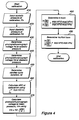
- the final steps, shown in Figure 3, blocks 330 and 340, are the calculations of the systolic and diastolic blood pressures, P s and P d , respectively, using the determined photoplethysmograph information and the constants determined in blocks 320 and 310.
- the information is output to medical personnel on a display 30. If more measurements are desired, decision block 350 causes blocks 320, 330, and 340 to be repeated. However, only one calibration phase 310 is required. These major steps are expanded upon below.
- the principle of the inventive method is derived from the Beer-Lambert law of analytical chemistry.
- the Beer-Lambert law gives the relationship between the absorption of monochromatic light by a concentration of a material in a solution as a function of the path length through the solution.
- V A o exp (-c t e t x t )exp (-c a e a x a )
- a o ZI o .
- This version has separable components, A o exp (-c t e t x t ) which relates to the conversion constant and the background tissues 16, and exp( -c a e a x a ), which relates to the arterial blood 10.
- V V o exp(-b ⁇ 1 ⁇ 2 ), where b is equal to c a e a (4/ ⁇ L) 1 ⁇ 2 , and L is the light path width through the artery 12.
- V s (u)exp((n)exp(-kP s )) for systolic Pressure
- V d (u)exp((n)exp(-kP d )) for diastolic Pressure
- V m (u)exp((n)exp(-kP m )) for mean Pressure
- V inf u
- V inf is the equivalent receiver voltage at infinite pressure and V0 is the equivalent receiver voltage at zero pressure.
- V d /V s exp((n)(exp(-kP d )-exp(-kP s )))
- V d /V m exp((n)(exp(-kP d )-exp(-kP m )))
- the previous section derived various relationships useful in the preferred method as outlined in Figure 3.
- the step of calibrating the photoplethysmograph outputs to the patient 9, shown in Figure 3, block 310 is shown in expanded detail in Figure 4.
- the first two steps, shown in block 410 and block 420 are the determination and entering of the systolic and diastolic blood pressures, P s and P d , respectively, at calibration into the computer 24.
- these blood pressures are determined by an auxiliary blood pressure instrument 20, preferably an accurate blood pressure cuff having direct inputs to the computer 24 via the instrument bus 28.
- the next two steps, shown in blocks 430 and 440 of Figure 4 are the determination of the photoplethysmograph voltages, V s and V d , from the receiver 18 output at the calibration systolic and diastolic blood pressures, respectively. These photoplethysmograph voltages are readily determined since they are the minimum and maximum output signals, respectively, from the A/D converter 23.
- the duration of the cardiac cycle, t d is determined from the output of the A/D converter 23. This is also readily accomplished by using a counter to determine the time between the diastolic voltages, times t0 and t1 of Figure 2.
- the preferred method requires that the area between the diastolic voltage V d and waveform function f(t), or ARC, be determined.
- ARC is easily performed using a digital computer since the output of the A/D converter 23 is a series of digital representations of the photoplethysmograph signals over time.
- Using the Simpson approximation to determine the integral is particularly expedient because the digital magnitudes can be multiplied by the sampling time between readings, then summed, to arrive at ARC. While ARC is preferably determined using integral equations, other methods of determining it are also acceptable.
- V m V d - (ARC/t d ); where all terms are as previously given.
- the patient's arterial blood pressures can be determined only from the photoplethysmograph output.
- the computer 24 monitors the photoplethysmograph outputs to determine, at the time of measurement, the systolic voltage V s , the diastolic voltage V d , the duration of the cardiac cycle t d and the ARC, as shown in blocks 510, 520, 530 and 540, of Figure 5 respectively.
- systolic and diastolic blood pressures are then available for output to medical personnel as shown in block 640, in a variety of way such as by digital or analog readouts, chart recorders, voice synthesis, or as in the present embodiment on a display monitor 30. If another set of measurements is desired then decision block 650 causes the flow shown in Figures 5 and 6 to be repeated.
- the preferred embodiment described above is useful, can be readily implemented on a digital computer, and provides accurate and rapid measurements of arterial blood pressures non-invasively and in a manner suitable for continuous measurements.
- the preferred method leads to inaccuracies because of time variations in V inf , the equivalent receiver voltage at infinite pressure.
- V inf in the preferred method was part of the ratio V0/V inf determined during calibration and presumed constant.
- the preferred embodiment can be modified to compensate for changes in V inf but at the expense of additional computation difficulty and time.
- the data gathering steps depicted in Figure 5 remain the same.
- the flow diagram of Figure 6 is modified to the procedural steps shown in Figure 8.
- V inf exp ⁇ ln(V s ) - [exp(-kP p )]lnV d ]/[1-exp(-kP p )] ⁇
- V s and V d are also the values at the time of measurement.
- This new V inf is then used in the equation of block 830, along with the previously stored value of V0, to determine the diastolic pressure P d .
- This alternative embodiment reduces the effects of changes in V inf .
- the calculation of the systolic pressure P s , shown in Block 840, and the output of the systolic and diastolic pressures, P d and P s , respectively, as shown in block 850 are performed in the same manner as they were in blocks 630 and 640, respectively, of Figure 6.
- the decision block 860 operates in the same manner as the decision block 650 in Figure 6.
- the apparatus for practicing the present invention uses a modified pulse oximeter-type photoplethysmograph 4 having numerous user controls, such as receiver 18 gain and light source 8 current settings. It outputs an analog voltage representation of the photodiode output to an analog-to-digital converter A/D 23 which digitizes the receiver 18 output and applies it to an IBM-AT type personal computer 24 under the control of software stored in a hard-disk drive.
- the display 30 output is on a computer monitor.
- the required auxiliary blood pressure instrument 20 readings are input by keyboard when directed by software programmed prompts.
- the separate photoplethysmograph 4, A/D converter 23, and computer 24 will probably be replace by similar structures within a single chassis and calibration data will be automatically inputted by an automatic blood pressure cuff.
Abstract
Description
- This invention relates generally to blood pressure measurements. More particularly, it relates to a method of non-invasively determining blood pressure using a photoplethysmograph.
- Arterial blood pressure measurements provide valuable information about a patient's condition. The heart's cyclical action produces a blood pressure maximum at systole, called systolic pressure, and a minimum pressure at diastole, called diastolic pressure. While the systolic and diastolic pressures are themselves important in gauging the patient's condition, other useful parameters are the mean (average) blood pressure during a heart cycle, and the pulse pressure, which is the arithmetic difference between the systolic and diastolic pressures.
- The importance of arterial blood pressure has spurred the development of numerous methods of determining it. The most widely used method is probably the familiar blood pressure cuff, which consists of an expandable ring (1) inflated to stop arterial blood flow and (2) then gradually contracted. Using a stethoscope, medical personnel listen to the artery to determine at what pressure blood flow begins, establishing the systolic pressure, and at what pressure flow is unrestricted, establishing the diastolic pressure. More advanced blood pressure monitoring systems plot the arterial blood pressure through a complete heart cycle. Typically, these systems use catheters having piezoelectric pressure transducers that produce output signals dependent upon the instantaneous blood pressure. The output signals are monitored and used to determine the arterial blood pressures over a complete heart cycle. These systems are advantageous in that the blood pressure is continuously measured and displayed.
- While prior art methods are useful, they have disadvantages. Cuff-type systems require restricting arterial blood flow and are not suitable for continuous use. The piezoelectric-type systems generally require undesirable invasive techniques, costly disposable materials, and time and skill to set-up. However, during certain critical periods, such as surgery, continuous arterial blood pressure monitoring is highly desirable. Therefore, it would be beneficial to have a method of continuously and non-invasively measuring a patient's blood pressure.
- Photoplethysmographs are well-known instruments which use light for determining and registering variations in a patient's blood volume. They can instantaneously track arterial blood volume changes during the cardiac cycle. Since photoplethysmographs operate non-invasively, much work has gone into using them to determine blood pressure. In 1983, inventor Warner was issued U.S. Patent No. 4,418,700 on a method of determining circulatory parameters, wherein signals from a photoplethysmograph were used to determine arterial blood pressure.
- Significant problems were found when investigating the Warner method. Therefore, it is clear that the need for a practical method of continuously and non-invasively monitoring arterial blood pressure has remained.
- From EP-A-160 994 a non-invasive method for determining heart-related parameters in patients by means of a photoelectric plethysmograph is known. The method determines pulse pressure, time constant of the arterial system, systolic and diastolic pressure, peripheral resistance, cardiac output and mean arterial blood pressure.
- The object of the present invention is to provide an improved method for a continuously and non-invasively measuring arterial blood pressure.
- This object is solved by a method comprising the steps of
patent claim 1. - Preferred embodiments of subject to various dependent claims
- The present invention will be more clearly understood from the description of the preferred embodiments which are explained with reference to the accompanying drawings in which:
- Figure 1 is a partial cutaway view, partial application depiction, and partial block diagram illustrating a preferred method in operation.
- Figure 2 is a sketch of the output waveform from a photoplethysmograph receiver over two cardiac cycles.
- Figure 3 is a block diagram illustrating the basic procedural steps of the preferred method of Figure 1.
- Figure 4 is a flow diagram of the preferred procedure for calibrating the photoplethysmograph output to a patient according to the inventive method.
- Figure 5 is a flow diagram of the output monitoring and data acquisition steps according of the inventive method.
- Figure 6 is a flow diagram outlining the preferred procedural steps for arterial blood pressure determination according to the inventive method.
- Figure 7 is a flow diagram of an alternative procedure for calibrating the photoplethysmograph output to a patient according to the inventive method.
- Figure 8 is a flow diagram outlining alternative procedural steps for arterial blood pressure determination according to the inventive method.
- A preferred embodiment of the present invention, shown in Figure 1, uses a
transmitter 2 portion of a photoplethysmograph 4 to cause monochromatic light 6, preferably in the red and IR ranges, to be emitted from aphotodiode light source 8. The emitted monochromatic light 6 travels through apatient 9, along a light path which includesblood 10 in anartery 12, to aphotodiode light detector 14. Whileartery 12 has been described, and is shown in Figure 1, as a single artery, in all practical cases the light path actually passes through many arteries. These arteries can be lumped together and treated as if only oneartery 12 existed. Therefore, for simplicity, the remainder of this application will only discuss oneartery 12, but it is to be understood that it represents the composite effects of many individual arteries. The light path is also throughbackground tissue 16. Thetransmitter 2 controls the amount of monochromatic light 6 emitted by varying the amount of current through thelight source 8. In the preferred embodiment, thetransmitter 2 regulates the monochromatic light 6 at a fixed level. - As the monochromatic light 6 travels along its light path it is partially absorbed by the
background tissue 16 and theblood 10. A portion of the monochromatic light 6 is not absorbed and impinges on thelight detector 14, creating electrical signals which are applied to areceiver 18 of the photoplethysmograph 4. The magnitudes of these electrical signals depend upon the amount of monochromatic light emitted by thelight source 8, the path lengths through thebackground tissue 16 and theblood 10, the amount of light absorbed per unit length by theblood 10 andtissue 16, the conversion efficiency of thelight detector 14, and various lumped losses such as poor focusing of the monochromatic light 6. - Since the
artery 12 is pliant, as blood pressure increase so does the volume ofblood 10 within theartery 12. As the heart beats, its cyclical action causes the arterial blood pressure to change. This causes the electrical signals to change since the path length through theblood 10 changes, causing the amount of monochromatic light 6 absorbed by theblood 10 to change. Therefore, the electrical signals from thelight detector 14 applied to thereceiver 18 is a function of the arterial blood pressure. - The
receiver 18 amplifies the electrical signals to a usable level and applies them as analog signals, via areceiver line 22, to an analog-to-digital converter A/D 23. The A/D 23 converts the outputs of thereceiver 18 to time sampled digital signals which are applied to thecomputer 24 via a computer bus 25. - The signals on the
receiver line 22 can be represented by thephotoplethysmograph output waveform 26, shown in Figure 2 for two cardiac cycles. The horizontal axis designates time and, in the present apparatus, the vertical axis designates volts, but current levels would also be suitable. Times t0 and t1, denoting the beginning of each cardiac cycle, are clearly marked. Thewaveform 26 can be described mathematically as a function of time, with the description being f(t). The voltage waveform is inverted from the common pressure waveform because the voltage corresponds to transmitted light. The highest voltage obtained over a cardiac cycle, Vd, coincides with the diastolic pressure and the lowest voltage, Vs, coincides with the systolic pressure. Between Vs and Vd is a mean pressure voltage Vm, which corresponds to the mean, or average, arterial pressure over a full cardiac cycle. The duration of the cardiac cycle, td is the time between reoccurrences of the diastolic or systolic voltages. The area between the waveform function f(t) and the diastolic voltage line, shown in crosshatch in Figure 2, is called the "ARC." The particular values for Vs, Vm, Vd, as well as the waveform function f(t) and the area ARC, change with different patients, photoplethysmographs, sensor locations, and photoplethysmograph settings. However, these parameters are functions of the arterial blood pressure. - In a preferred method of the present invention, three major steps are used to determine arterial blood pressure, shown in Figure 3. The first, shown in
block 310, is the calibration of the photoplethysmograph output to the patient. Referring now to Figure 1, the calibration is accomplished by matching the photoplethysmograph output on thecomputer bus 28 at the time of calibration with the systolic, Ps, and diastolic Pd, blood pressures from the auxiliaryblood pressure instrument 20. In the preferred embodiment, these blood pressure measurements are entered via a keyboard to thecomputer 24. However, preferably this information would be entered directly via aninstrument bus 28. The photoplethysmograph output is compared with the systolic and diastolic pressures, Ps and Pd, from the auxiliaryblood pressure instrument 20 and several constants are determined, as is subsequently discussed. - As is shown in Figure 3, block 320, the next step is the measurement of the photoplethysmograph outputs during a measurement period to determine various information. This information includes the systolic, mean, and diastolic photoplethysmograph voltages Vs, Vm, and Vd, respectively, the cardiac duration td, and the ARC. The final steps, shown in Figure 3, blocks 330 and 340, are the calculations of the systolic and diastolic blood pressures, Ps and Pd, respectively, using the determined photoplethysmograph information and the constants determined in
blocks display 30. If more measurements are desired,decision block 350 causesblocks calibration phase 310 is required. These major steps are expanded upon below. - The principle of the inventive method is derived from the Beer-Lambert law of analytical chemistry. The Beer-Lambert law gives the relationship between the absorption of monochromatic light by a concentration of a material in a solution as a function of the path length through the solution. Mathematically, the Beer-Lambert law is expressed as:

- The present invention analogizes
blood 10 andtissue 16 density to concentration, modifies the Beer-Lambert law so that the light intensity terms are given in terms ofreceiver 18 output voltages, and breaks the light path into individual lengths containing thebackground tissues 16 and thearterial blood 10. Therefore, the modified version of the Beer-Lambert law is:
background tissues 16, a refers to theblood 10 in theartery 12, V is an equivalent transmission voltage corresponding to the transmitted light, and Z is a constant relating light intensity to thereceiver 18 output voltage. - This can be simplified to:


- This version has separable components, Aoexp(-c t e t x t ) which relates to the conversion constant and the
background tissues 16, and exp(-c a e a x a), which relates to thearterial blood 10. For simplicity, the first component can be given as


artery 12. Taking the natural logarithm results in:

artery 12, and P is the instantaneous arterial blood pressure. This arterial volume-pressure relationship is a good approximation at the pressures of interest. Substituting this formula for ψ in the logarithmic version:


- Establishing various ratios:


- The previous section derived various relationships useful in the preferred method as outlined in Figure 3. The step of calibrating the photoplethysmograph outputs to the
patient 9, shown in Figure 3, block 310 is shown in expanded detail in Figure 4. The first two steps, shown inblock 410 and block 420 are the determination and entering of the systolic and diastolic blood pressures, Ps and Pd, respectively, at calibration into thecomputer 24. As previously indicated and as shown in Figure 1, these blood pressures are determined by an auxiliaryblood pressure instrument 20, preferably an accurate blood pressure cuff having direct inputs to thecomputer 24 via theinstrument bus 28. - The next two steps, shown in
blocks receiver 18 output at the calibration systolic and diastolic blood pressures, respectively. These photoplethysmograph voltages are readily determined since they are the minimum and maximum output signals, respectively, from the A/D converter 23. Next, as shown inblock 450, the duration of the cardiac cycle, td is determined from the output of the A/D converter 23. This is also readily accomplished by using a counter to determine the time between the diastolic voltages, times t₀ and t₁ of Figure 2. - To determine various patient arterial constants, the preferred method requires that the area between the diastolic voltage Vd and waveform function f(t), or ARC, be determined. This step is shown in
block 460 and is preferably accomplished by determining the integral of the photoplethysmograph voltages over the cardiac cycle using:
D converter 23 is a series of digital representations of the photoplethysmograph signals over time. Using the Simpson approximation to determine the integral is particularly expedient because the digital magnitudes can be multiplied by the sampling time between readings, then summed, to arrive at ARC. While ARC is preferably determined using integral equations, other methods of determining it are also acceptable. - Next, as shown in
block 470, the photoplethysmograph voltage, Vm corresponding to the mean pressure is determined from the formula
- With Vm known, the next steps, shown in
block 

block 320 of Figure 3 and with expanded detail in Figure 5. Referring to Figure 5, when arterial blood pressures are to be determined, thecomputer 24 monitors the photoplethysmograph outputs to determine, at the time of measurement, the systolic voltage Vs, the diastolic voltage Vd, the duration of the cardiac cycle td and the ARC, as shown inblocks computer 24 then determines, as shown in block 550, the equivalent photoplethysmograph voltage Vm using the formula:
computer 24 determines the patient's systolic and diastolic blood pressures as shown in the flow chart of Figure 6, which is a more detailed description ofblocks block 610, to first calculate the pulse pressure Pp, using numerical methods, from the formula:
block 620, using the formula
block 630, using the equation
While the above is the preferred method of calculating arterial systolic and diastolic blood pressures from the photoplethysmograph outputs, other schemes are possible. - The systolic and diastolic blood pressures are then available for output to medical personnel as shown in
block 640, in a variety of way such as by digital or analog readouts, chart recorders, voice synthesis, or as in the present embodiment on adisplay monitor 30. If another set of measurements is desired then decision block 650 causes the flow shown in Figures 5 and 6 to be repeated. - The preferred embodiment described above is useful, can be readily implemented on a digital computer, and provides accurate and rapid measurements of arterial blood pressures non-invasively and in a manner suitable for continuous measurements. However, in some patients and under some conditions, the preferred method leads to inaccuracies because of time variations in Vinf, the equivalent receiver voltage at infinite pressure. Vinf, in the preferred method was part of the ratio V₀/Vinf determined during calibration and presumed constant. The preferred embodiment can be modified to compensate for changes in Vinf but at the expense of additional computation difficulty and time.
- The alternative embodiment follows the same three major steps as shown in Figure 3 for the preferred embodiment. However, the calibration procedure of Figure 4 is modified to that shown in Figure 7. These calibration procedures, shown in Figure 7
blocks 710 through 780, are identical until Vinf is determined inblock 790. It can be shown that Vinf is determinable by the following formula:
block 790, V₀, the equivalent receiver voltage at zero pressure, is determined, as shown inblock 799, from the formula:
- According to the alternative embodiment, the data gathering steps depicted in Figure 5 remain the same. However, during blood pressure determination, the flow diagram of Figure 6 is modified to the procedural steps shown in Figure 8. Referring now to Figure 8, after determination of the pulse pressure Pp in
block 810, in the same manner as it was determined inblock 610, the Vinf at the time of measurement is determined, as shown inblock 820, from equation:
- This new Vinf is then used in the equation of
block 830, along with the previously stored value of V₀, to determine the diastolic pressure Pd. This alternative embodiment reduces the effects of changes in Vinf. The calculation of the systolic pressure Ps, shown inBlock 840, and the output of the systolic and diastolic pressures, Pd and Ps, respectively, as shown inblock 850 are performed in the same manner as they were inblocks decision block 860 operates in the same manner as thedecision block 650 in Figure 6. - The apparatus for practicing the present invention uses a modified pulse oximeter-type photoplethysmograph 4 having numerous user controls, such as
receiver 18 gain andlight source 8 current settings. It outputs an analog voltage representation of the photodiode output to an analog-to-digital converter A/D 23 which digitizes thereceiver 18 output and applies it to an IBM-AT typepersonal computer 24 under the control of software stored in a hard-disk drive. Thedisplay 30 output is on a computer monitor. The required auxiliaryblood pressure instrument 20 readings are input by keyboard when directed by software programmed prompts. In future applications, the separate photoplethysmograph 4, A/D converter 23, andcomputer 24 will probably be replace by similar structures within a single chassis and calibration data will be automatically inputted by an automatic blood pressure cuff. - From the foregoing, it will be appreciated that the invention, as described herein for purposes of illustration, provides an advancement in non-invasive blood pressure instruments. Although alternative embodiments have been described herein, various modifications may be made without departing from the scope of the present invention. Accordingly, the scope of the invention extends to the broad general meaning of the appended claims.
Claims (10)
- A method of determining systolic and diastolic arterial blood pressures using a photoplethysmograph including a photoplethysmograph sensor (8) having light passing through an artery (12) of a patient (9), the photoplethysmograph generating an electrical output signal having a predetermined relationship to the volume of blood in the artery (12), the method comprising the steps of:
calibrating the photoplethysmograph (4) during a calibration period (310) by determining the actual arterial blood pressure of the patient (9) by means (20) other than the photoplethysmograph (4), characterized by determining the value of a first arterial constant (k) in a predetermined relationship
analyzing and gathering data from the photoplethysmograph output signal during a measurement period to determine the arterial systolic and diastolic blood pressures corresponding to the output signal in accordance with said predetermined relationship defining arterial blood pressure (P) as a function of arterial blood volume (ψ) as indicated by the photoplethysmograph output signal, the first arterial constant (k) as determined in the preceding step, and the conversion constant (ψinf) corresponding to arterial blood volume at infinite pressure. - The method of claim 1 wherein said conversion constant (ψinf) corresponding to arterial blood volume at infinite pressure is determined by examining the relationship between arterial blood volume and arterial blood pressure, and then determining said arterial blood volume at infinite pressure as the asymptotic value of arterial blood volume in said relationship.
- The method of claim 1, further including the steps of determining from said photoplethysmograph output signal a value td corresponding to the duration of the cardiac cycle during said measurement period, a value S corresponding to systolic pressure during said measurement period, a value D corresponding to diastolic pressure during said measurement period, and a value ARC corresponding to the integral with respect to time of the difference between the photoplethysmograph output signal during said measurement period and a value of said photoplethysmograph output signal corresponding to diastolic pressure.
- The method of claim 1, wherein said step of calibrating said photoplethysmograph during a calibration period includes the steps of:
determining the actual arterial systolic, diastolic, and mean blood pressures, Ps, Pd, and Pm, respectively, during said calibration period by means other than said photoplethysmograph;
determining values Vd and Vs of said photoplethysmograph output signal corresponding to respective diastolic and systolic arterial pressures during said calibration period;
determining the value Vm corresponding to the mean of said photoplethysmograph output signal during said calibration period; and
calculating said first arterial constant k from the relationship:
- The method of claim 4, wherein said step of determining a value Vm corresponding to the mean of said photoplethysmograph output signal during said calibration period is accomplished by calculating Vm from the relationship:

- The method of claim 1 further including the step of determining from said photoplethysmograph output signal a value X corresponding to arterial pulse pressure during said measurement period by the steps of:
determining values Vd and Vs of said photoplethysmograph output signal corresponding to respective diastolic and systolic arterial pressures during said calibration period;
determining a value Vm corresponding to the mean of said photoplethysmograph output signal during said calibration period; and
calculating the value X corresponding to arterial pulse pressure during said measurement period from the relationship:
- The method of claim 6, wherein said step of calibrating said photoplethysmograph during said calibration period further includes the steps of:
determining the actual arterial systolic and diastolic blood pressures, Ps and Pd, respectively, during said calibration period by means other than said photoplethysmograph;
calculating the ratio V₀/Vinf during said calibration period from the relationship:
- The method of claim 7 further including the step of determining from said photoplethysmograph output signal a value D corresponding to diastolic pressure during said measurement period by calculating D from the relationship:

- The method of claim 6, wherein said step of calibrating said photoplethysmograph during said calibration period further includes the step of:
determining Vinf at said calibration period from the relationship:

- The method of claim 9 further including the step of determining from said photoplethysmograph output signal a value D corresponding to diastolic pressure during said measurement period by calculating D from the relationship:

Applications Claiming Priority (5)
| Application Number | Priority Date | Filing Date | Title |
|---|---|---|---|
| US57915990A | 1990-09-06 | 1990-09-06 | |
| US579159 | 1990-09-06 | ||
| US07/656,021 US5140990A (en) | 1990-09-06 | 1991-02-15 | Method of measuring blood pressure with a photoplethysmograph |
| US656021 | 1991-02-15 | ||
| PCT/US1991/006914 WO1992003967A2 (en) | 1990-09-06 | 1991-09-06 | A method of measuring blood pressure with a photoplethysmograph |
Publications (2)
| Publication Number | Publication Date |
|---|---|
| EP0498885A1 EP0498885A1 (en) | 1992-08-19 |
| EP0498885B1 true EP0498885B1 (en) | 1996-05-22 |
Family
ID=27077687
Family Applications (1)
| Application Number | Title | Priority Date | Filing Date |
|---|---|---|---|
| EP91918602A Expired - Lifetime EP0498885B1 (en) | 1990-09-06 | 1991-09-06 | A method of measuring blood pressure with a photoplethysmograph |
Country Status (5)
| Country | Link |
|---|---|
| US (1) | US5140990A (en) |
| EP (1) | EP0498885B1 (en) |
| CA (1) | CA2073019A1 (en) |
| DE (1) | DE69119741T2 (en) |
| WO (1) | WO1992003967A2 (en) |
Cited By (1)
| Publication number | Priority date | Publication date | Assignee | Title |
|---|---|---|---|---|
| WO2019091517A1 (en) | 2017-11-13 | 2019-05-16 | Technische Universität Dresden | Method for determining blood pressure while taking a physiological parameter into consideration |
Families Citing this family (112)
| Publication number | Priority date | Publication date | Assignee | Title |
|---|---|---|---|---|
| US5423322A (en) * | 1988-12-29 | 1995-06-13 | Medical Physics, Inc. | Total compliance method and apparatus for noninvasive arterial blood pressure measurement |
| US5269310A (en) * | 1990-09-06 | 1993-12-14 | Spacelabs Medical, Inc. | Method of measuring blood pressure with a plethysmograph |
| US5485848A (en) * | 1991-01-31 | 1996-01-23 | Jackson; Sandra R. | Portable blood pressure measuring device and method of measuring blood pressure |
| DE4226972A1 (en) * | 1992-08-14 | 1994-02-17 | Vladimir Dr Blazek | Non-invasive measurement of venous and arterial blood pressure in finger or toe - correlating slow increase from zero air pressure in cuff, caused by electronically-controlled pump, with change in venous signal from reflection or transmission photoplethysmograph sensor |
| FR2726457B1 (en) * | 1994-11-08 | 1998-08-28 | Lavoisier Pierre | MEASUREMENT PROCESS CONCERNING THE RIGIDITY OF A PENIS AND DEVICE FOR CARRYING OUT THIS METHOD |
| JP3666987B2 (en) * | 1996-05-02 | 2005-06-29 | コーリンメディカルテクノロジー株式会社 | Blood pressure monitoring device |
| US5752920A (en) * | 1996-08-01 | 1998-05-19 | Colin Corporation | Blood pressure monitor apparatus |
| US5865755A (en) * | 1996-10-11 | 1999-02-02 | Dxtek, Inc. | Method and apparatus for non-invasive, cuffless, continuous blood pressure determination |
| US5991654A (en) * | 1997-06-06 | 1999-11-23 | Kci New Technologies, Inc. | Apparatus and method for detecting deep vein thrombosis |
| JP2000157499A (en) | 1998-11-27 | 2000-06-13 | Nippon Colin Co Ltd | Blood pressure monitoring device |
| US6331162B1 (en) | 1999-02-01 | 2001-12-18 | Gary F. Mitchell | Pulse wave velocity measuring device |
| GB2356252B (en) * | 1999-11-12 | 2004-02-25 | Micro Medical Ltd | Apparatus for measuring the shape of an arterial pressure pulse in a person |
| US6616613B1 (en) | 2000-04-27 | 2003-09-09 | Vitalsines International, Inc. | Physiological signal monitoring system |
| US6533729B1 (en) | 2000-05-10 | 2003-03-18 | Motorola Inc. | Optical noninvasive blood pressure sensor and method |
| US6475153B1 (en) | 2000-05-10 | 2002-11-05 | Motorola Inc. | Method for obtaining blood pressure data from optical sensor |
| JP2002172095A (en) * | 2000-12-06 | 2002-06-18 | K & S:Kk | Pulse measurement device |
| US7473231B2 (en) * | 2002-06-25 | 2009-01-06 | Francis Y. Falck | Method and apparatus for examining an eye |
| US7819811B2 (en) * | 2002-11-06 | 2010-10-26 | Itamar Medical Ltd. | Detecting medical conditions with noninvasive body probes |
| US20050148882A1 (en) * | 2004-01-06 | 2005-07-07 | Triage Wireless, Incc. | Vital signs monitor used for conditioning a patient's response |
| US20060142648A1 (en) * | 2003-01-07 | 2006-06-29 | Triage Data Networks | Wireless, internet-based, medical diagnostic system |
| US7435214B2 (en) * | 2004-01-29 | 2008-10-14 | Cannuflow, Inc. | Atraumatic arthroscopic instrument sheath |
| US20050216199A1 (en) * | 2004-03-26 | 2005-09-29 | Triage Data Networks | Cuffless blood-pressure monitor and accompanying web services interface |
| US20060009697A1 (en) * | 2004-04-07 | 2006-01-12 | Triage Wireless, Inc. | Wireless, internet-based system for measuring vital signs from a plurality of patients in a hospital or medical clinic |
| US7004907B2 (en) * | 2004-04-07 | 2006-02-28 | Triage Wireless, Inc. | Blood-pressure monitoring device featuring a calibration-based analysis |
| US20060009698A1 (en) * | 2004-04-07 | 2006-01-12 | Triage Wireless, Inc. | Hand-held monitor for measuring vital signs |
| US20050228297A1 (en) * | 2004-04-07 | 2005-10-13 | Banet Matthew J | Wrist-worn System for Measuring Blood Pressure |
| US20050228244A1 (en) * | 2004-04-07 | 2005-10-13 | Triage Wireless, Inc. | Small-scale, vital-signs monitoring device, system and method |
| US7179228B2 (en) * | 2004-04-07 | 2007-02-20 | Triage Wireless, Inc. | Cuffless system for measuring blood pressure |
| US20050261598A1 (en) * | 2004-04-07 | 2005-11-24 | Triage Wireless, Inc. | Patch sensor system for measuring vital signs |
| US7238159B2 (en) * | 2004-04-07 | 2007-07-03 | Triage Wireless, Inc. | Device, system and method for monitoring vital signs |
| US20050228300A1 (en) * | 2004-04-07 | 2005-10-13 | Triage Data Networks | Cuffless blood-pressure monitor and accompanying wireless mobile device |
| US20060047447A1 (en) * | 2004-08-24 | 2006-03-02 | Impact Sports Technologies, Inc. | System, method and device for monitoring an athlete |
| US7502498B2 (en) | 2004-09-10 | 2009-03-10 | Available For Licensing | Patient monitoring apparatus |
| US9820658B2 (en) | 2006-06-30 | 2017-11-21 | Bao Q. Tran | Systems and methods for providing interoperability among healthcare devices |
| US20060079794A1 (en) * | 2004-09-28 | 2006-04-13 | Impact Sports Technologies, Inc. | Monitoring device, method and system |
| US7887492B1 (en) | 2004-09-28 | 2011-02-15 | Impact Sports Technologies, Inc. | Monitoring device, method and system |
| US20060253010A1 (en) * | 2004-09-28 | 2006-11-09 | Donald Brady | Monitoring device, method and system |
| US7544168B2 (en) * | 2004-09-30 | 2009-06-09 | Jerusalem College Of Technology | Measuring systolic blood pressure by photoplethysmography |
| US20060084878A1 (en) * | 2004-10-18 | 2006-04-20 | Triage Wireless, Inc. | Personal computer-based vital signs monitor |
| US7658716B2 (en) * | 2004-12-07 | 2010-02-09 | Triage Wireless, Inc. | Vital signs monitor using an optical ear-based module |
| US7420472B2 (en) | 2005-10-16 | 2008-09-02 | Bao Tran | Patient monitoring apparatus |
| US7733224B2 (en) | 2006-06-30 | 2010-06-08 | Bao Tran | Mesh network personal emergency response appliance |
| US20070142715A1 (en) * | 2005-12-20 | 2007-06-21 | Triage Wireless, Inc. | Chest strap for measuring vital signs |
| US20070185393A1 (en) * | 2006-02-03 | 2007-08-09 | Triage Wireless, Inc. | System for measuring vital signs using an optical module featuring a green light source |
| RU2309668C1 (en) * | 2006-02-20 | 2007-11-10 | Александр Сергеевич Парфенов | Method and device for non-invasive measurement of function of endothelium |
| US9060683B2 (en) | 2006-05-12 | 2015-06-23 | Bao Tran | Mobile wireless appliance |
| US8684922B2 (en) | 2006-05-12 | 2014-04-01 | Bao Tran | Health monitoring system |
| US7539532B2 (en) | 2006-05-12 | 2009-05-26 | Bao Tran | Cuffless blood pressure monitoring appliance |
| US7558622B2 (en) | 2006-05-24 | 2009-07-07 | Bao Tran | Mesh network stroke monitoring appliance |
| US8323189B2 (en) | 2006-05-12 | 2012-12-04 | Bao Tran | Health monitoring appliance |
| US8968195B2 (en) | 2006-05-12 | 2015-03-03 | Bao Tran | Health monitoring appliance |
| US8500636B2 (en) | 2006-05-12 | 2013-08-06 | Bao Tran | Health monitoring appliance |
| US8684900B2 (en) | 2006-05-16 | 2014-04-01 | Bao Tran | Health monitoring appliance |
| US7539533B2 (en) * | 2006-05-16 | 2009-05-26 | Bao Tran | Mesh network monitoring appliance |
| US7993275B2 (en) * | 2006-05-25 | 2011-08-09 | Sotera Wireless, Inc. | Bilateral device, system and method for monitoring vital signs |
| US9149192B2 (en) * | 2006-05-26 | 2015-10-06 | Sotera Wireless, Inc. | System for measuring vital signs using bilateral pulse transit time |
| US8442607B2 (en) | 2006-09-07 | 2013-05-14 | Sotera Wireless, Inc. | Hand-held vital signs monitor |
| US20080082004A1 (en) * | 2006-09-08 | 2008-04-03 | Triage Wireless, Inc. | Blood pressure monitor |
| US8449469B2 (en) * | 2006-11-10 | 2013-05-28 | Sotera Wireless, Inc. | Two-part patch sensor for monitoring vital signs |
| US20080221461A1 (en) * | 2007-03-05 | 2008-09-11 | Triage Wireless, Inc. | Vital sign monitor for cufflessly measuring blood pressure without using an external calibration |
| US20080221399A1 (en) * | 2007-03-05 | 2008-09-11 | Triage Wireless, Inc. | Monitor for measuring vital signs and rendering video images |
| US7922664B2 (en) * | 2007-04-05 | 2011-04-12 | Coherence Llc | Method and system for improving physiologic status and health via assessment of the dynamic respiratory arterial pressure wave using plethysmographic technique |
| US8750971B2 (en) | 2007-05-24 | 2014-06-10 | Bao Tran | Wireless stroke monitoring |
| US11607152B2 (en) | 2007-06-12 | 2023-03-21 | Sotera Wireless, Inc. | Optical sensors for use in vital sign monitoring |
| WO2008154643A1 (en) * | 2007-06-12 | 2008-12-18 | Triage Wireless, Inc. | Vital sign monitor for measuring blood pressure using optical, electrical, and pressure waveforms |
| US8602997B2 (en) * | 2007-06-12 | 2013-12-10 | Sotera Wireless, Inc. | Body-worn system for measuring continuous non-invasive blood pressure (cNIBP) |
| US11330988B2 (en) | 2007-06-12 | 2022-05-17 | Sotera Wireless, Inc. | Body-worn system for measuring continuous non-invasive blood pressure (cNIBP) |
| US8398556B2 (en) * | 2008-06-30 | 2013-03-19 | Covidien Lp | Systems and methods for non-invasive continuous blood pressure determination |
| US20090326386A1 (en) * | 2008-06-30 | 2009-12-31 | Nellcor Puritan Bennett Ireland | Systems and Methods for Non-Invasive Blood Pressure Monitoring |
| US20100081946A1 (en) * | 2008-09-26 | 2010-04-01 | Qualcomm Incorporated | Method and apparatus for non-invasive cuff-less blood pressure estimation using pulse arrival time and heart rate with adaptive calibration |
| ES2336997B1 (en) | 2008-10-16 | 2011-06-13 | Sabirmedical,S.L. | SYSTEM AND APPARATUS FOR NON-INVASIVE MEASUREMENT OF BLOOD PRESSURE. |
| US8057400B2 (en) | 2009-05-12 | 2011-11-15 | Angiologix, Inc. | System and method of measuring changes in arterial volume of a limb segment |
| US11896350B2 (en) | 2009-05-20 | 2024-02-13 | Sotera Wireless, Inc. | Cable system for generating signals for detecting motion and measuring vital signs |
| US8956294B2 (en) | 2009-05-20 | 2015-02-17 | Sotera Wireless, Inc. | Body-worn system for continuously monitoring a patients BP, HR, SpO2, RR, temperature, and motion; also describes specific monitors for apnea, ASY, VTAC, VFIB, and ‘bed sore’ index |
| US8738118B2 (en) * | 2009-05-20 | 2014-05-27 | Sotera Wireless, Inc. | Cable system for generating signals for detecting motion and measuring vital signs |
| US9775529B2 (en) * | 2009-06-17 | 2017-10-03 | Sotera Wireless, Inc. | Body-worn pulse oximeter |
| US11253169B2 (en) | 2009-09-14 | 2022-02-22 | Sotera Wireless, Inc. | Body-worn monitor for measuring respiration rate |
| US8545417B2 (en) * | 2009-09-14 | 2013-10-01 | Sotera Wireless, Inc. | Body-worn monitor for measuring respiration rate |
| US8321004B2 (en) * | 2009-09-15 | 2012-11-27 | Sotera Wireless, Inc. | Body-worn vital sign monitor |
| US8527038B2 (en) * | 2009-09-15 | 2013-09-03 | Sotera Wireless, Inc. | Body-worn vital sign monitor |
| US20110066044A1 (en) * | 2009-09-15 | 2011-03-17 | Jim Moon | Body-worn vital sign monitor |
| US8364250B2 (en) * | 2009-09-15 | 2013-01-29 | Sotera Wireless, Inc. | Body-worn vital sign monitor |
| US10420476B2 (en) | 2009-09-15 | 2019-09-24 | Sotera Wireless, Inc. | Body-worn vital sign monitor |
| US10806351B2 (en) * | 2009-09-15 | 2020-10-20 | Sotera Wireless, Inc. | Body-worn vital sign monitor |
| US8727977B2 (en) * | 2010-03-10 | 2014-05-20 | Sotera Wireless, Inc. | Body-worn vital sign monitor |
| US8747330B2 (en) | 2010-04-19 | 2014-06-10 | Sotera Wireless, Inc. | Body-worn monitor for measuring respiratory rate |
| US9173594B2 (en) | 2010-04-19 | 2015-11-03 | Sotera Wireless, Inc. | Body-worn monitor for measuring respiratory rate |
| US9339209B2 (en) | 2010-04-19 | 2016-05-17 | Sotera Wireless, Inc. | Body-worn monitor for measuring respiratory rate |
| US8979765B2 (en) | 2010-04-19 | 2015-03-17 | Sotera Wireless, Inc. | Body-worn monitor for measuring respiratory rate |
| US9173593B2 (en) | 2010-04-19 | 2015-11-03 | Sotera Wireless, Inc. | Body-worn monitor for measuring respiratory rate |
| US8888700B2 (en) | 2010-04-19 | 2014-11-18 | Sotera Wireless, Inc. | Body-worn monitor for measuring respiratory rate |
| US20140249432A1 (en) | 2010-12-28 | 2014-09-04 | Matt Banet | Body-worn system for continuous, noninvasive measurement of cardiac output, stroke volume, cardiac power, and blood pressure |
| US8761853B2 (en) | 2011-01-20 | 2014-06-24 | Nitto Denko Corporation | Devices and methods for non-invasive optical physiological measurements |
| CN103582449B (en) | 2011-02-18 | 2017-06-09 | 索泰拉无线公司 | For the modularization wrist wearing type processor of patient monitoring |
| SG192835A1 (en) | 2011-02-18 | 2013-09-30 | Sotera Wireless Inc | Optical sensor for measuring physiological properties |
| GB201111138D0 (en) | 2011-06-30 | 2011-08-17 | Leman Micro Devices Uk Ltd | Personal health data collection |
| WO2013076722A1 (en) | 2011-11-24 | 2013-05-30 | Itamar Medical Ltd. | Apparatus for monitoring arterial pulse waves in diagnosing various medical conditions |
| JP6054543B2 (en) * | 2012-12-04 | 2016-12-27 | コーニンクレッカ フィリップス エヌ ヴェKoninklijke Philips N.V. | Device and method for obtaining vital sign information of a living body |
| US9865176B2 (en) | 2012-12-07 | 2018-01-09 | Koninklijke Philips N.V. | Health monitoring system |
| RU2655518C2 (en) | 2013-02-13 | 2018-05-28 | Леман Майкро Дивайсиз Са | Noninvasive blood analysis |
| US20190142286A1 (en) * | 2014-03-31 | 2019-05-16 | Sensogram Technologies, Inc. | Photoplethysmographic wearable blood pressure monitoring system and methods |
| US10117586B1 (en) | 2014-03-31 | 2018-11-06 | Sensogram Technologies, Inc. | Continuous non-invasive wearable blood pressure monitoring system |
| JP6669950B2 (en) | 2014-10-27 | 2020-03-18 | バイタル サイネス インターナショナル インコーポレイテッドVital Sines International Inc. | System and method for monitoring aortic pulse wave velocity and blood pressure |
| KR101656369B1 (en) | 2015-04-20 | 2016-09-09 | 연세대학교 산학협력단 | System and method of diagonizing blood pressure with a single photoplethysmography |
| WO2016176218A1 (en) * | 2015-04-27 | 2016-11-03 | Apple Inc. | Dynamically reconfigurable apertures for optimization of ppg signal and ambient light mitigation |
| CN107920758B (en) | 2015-06-18 | 2023-07-18 | 瑞士Csem电子显微技术研发中心 | Method, device and computer program for determining a blood pressure value |
| WO2017040340A1 (en) * | 2015-08-28 | 2017-03-09 | Oslermd, Inc. | Methods and apparatuses for measuring multiple vital signs based on arterial pressure waveforms |
| KR102487982B1 (en) * | 2015-10-02 | 2023-01-11 | 삼성전자주식회사 | Blood pressure measurement apparatus, and Blood pressure measurement apparatus using a process to choose light sources |
| US10694995B2 (en) | 2017-12-05 | 2020-06-30 | Renegade Optophysics, Llc | Diagnostic eye goggle system |
| US20210169355A1 (en) * | 2019-12-06 | 2021-06-10 | Savan Patel | Systems & Methods for Vascular Disease Prediction, Indication, or Diagnosis |
| CN113706984B (en) * | 2021-08-06 | 2022-07-12 | 西安交通大学 | Synchronous analog calibration device and method for blood pressure and reflective photoelectric accumulated wave |
| CN113670516B (en) * | 2021-08-12 | 2024-02-09 | 之江实验室 | Compression position positioning and pressure measuring method based on photoplethysmography imaging |
Citations (1)
| Publication number | Priority date | Publication date | Assignee | Title |
|---|---|---|---|---|
| US4418700A (en) * | 1981-03-11 | 1983-12-06 | Sylvia Warner | Method and apparatus for measurement of heart-related parameters |
Family Cites Families (11)
| Publication number | Priority date | Publication date | Assignee | Title |
|---|---|---|---|---|
| US4030485A (en) * | 1974-11-12 | 1977-06-21 | Glenfield Warner | Method and apparatus for continuously monitoring systolic blood pressure |
| US4105021A (en) * | 1976-08-13 | 1978-08-08 | Joseph H. Allen | Method and arrangement for measuring blood pressure |
| US4343314A (en) * | 1980-08-11 | 1982-08-10 | Bohumir Sramek | Non-invasive real time blood pressure measurement system |
| US4437469A (en) * | 1980-09-29 | 1984-03-20 | Rush-Presbyterian-St. Luke's Medical Center | System for determining characteristics of blood flow |
| NL8105381A (en) * | 1981-11-27 | 1983-06-16 | Tno | METHOD AND APPARATUS FOR CORRECTING THE CUFF PRESSURE IN MEASURING THE BLOOD PRESSURE IN A BODY PART USING A PLETHYSMOGRAPH. |
| JPS59181129A (en) * | 1983-03-31 | 1984-10-15 | 株式会社エー・アンド・ディ | Hemomanometer |
| US4718428A (en) * | 1984-02-17 | 1988-01-12 | Cortronic Corporation | Method for determining diastolic arterial blood pressure in a subject |
| EP0160994A3 (en) * | 1984-05-10 | 1987-02-04 | Warner, Sylvia | Heart-related parameters monitoring apparatus |
| US4834107A (en) * | 1984-05-10 | 1989-05-30 | Sylvia Warner | Heart-related parameters monitoring apparatus |
| US4819646A (en) * | 1986-08-18 | 1989-04-11 | Physio-Control Corporation | Feedback-controlled method and apparatus for processing signals used in oximetry |
| US4846189A (en) * | 1987-06-29 | 1989-07-11 | Shuxing Sun | Noncontactive arterial blood pressure monitor and measuring method |
-
1991
- 1991-02-15 US US07/656,021 patent/US5140990A/en not_active Expired - Fee Related
- 1991-09-06 WO PCT/US1991/006914 patent/WO1992003967A2/en active IP Right Grant
- 1991-09-06 CA CA002073019A patent/CA2073019A1/en not_active Abandoned
- 1991-09-06 DE DE69119741T patent/DE69119741T2/en not_active Expired - Fee Related
- 1991-09-06 EP EP91918602A patent/EP0498885B1/en not_active Expired - Lifetime
Patent Citations (1)
| Publication number | Priority date | Publication date | Assignee | Title |
|---|---|---|---|---|
| US4418700A (en) * | 1981-03-11 | 1983-12-06 | Sylvia Warner | Method and apparatus for measurement of heart-related parameters |
Cited By (1)
| Publication number | Priority date | Publication date | Assignee | Title |
|---|---|---|---|---|
| WO2019091517A1 (en) | 2017-11-13 | 2019-05-16 | Technische Universität Dresden | Method for determining blood pressure while taking a physiological parameter into consideration |
Also Published As
| Publication number | Publication date |
|---|---|
| WO1992003967A3 (en) | 1992-04-30 |
| DE69119741T2 (en) | 1996-10-02 |
| US5140990A (en) | 1992-08-25 |
| CA2073019A1 (en) | 1992-03-07 |
| EP0498885A1 (en) | 1992-08-19 |
| DE69119741D1 (en) | 1996-06-27 |
| WO1992003967A2 (en) | 1992-03-19 |
Similar Documents
| Publication | Publication Date | Title |
|---|---|---|
| EP0498885B1 (en) | A method of measuring blood pressure with a photoplethysmograph | |
| US5269310A (en) | Method of measuring blood pressure with a plethysmograph | |
| US7220230B2 (en) | Pressure-based system and method for determining cardiac stroke volume | |
| US6022320A (en) | Blood pressure monitor apparatus | |
| US5241966A (en) | Method and apparatus for measuring cardiac output | |
| JP3710823B2 (en) | Improved method and apparatus for measuring cardiac output | |
| US5865758A (en) | System for obtaining hemodynamic information | |
| EP0997103B1 (en) | Non-invasive and continuous blood-pressure estimation apparatus | |
| KR101286402B1 (en) | Mobile Diagnosis Device | |
| US5111817A (en) | Noninvasive system and method for enhanced arterial oxygen saturation determination and arterial blood pressure monitoring | |
| EP2074942B1 (en) | Method and apparatus for a continuous non-invasive and non-obstrusive monitoring of blood pressure | |
| US4418700A (en) | Method and apparatus for measurement of heart-related parameters | |
| US4869262A (en) | Device for displaying blood pressure | |
| EP0615723A1 (en) | Method and apparatus for measuring blood flow | |
| JPH01500493A (en) | Multi-pulse oxygen concentration measurement method and device | |
| JPH0614891A (en) | Continuous non-invasion blood pressure monitoring method and apparatus | |
| CN111493855B (en) | System and method for non-invasive measurement of individualized cardiac output | |
| JPH07327964A (en) | Instrument for measuring oxygen saturation degree and instrument for measuring concentration of light absorptive material in blood | |
| JP3107630B2 (en) | Pulse oximeter | |
| JP5203210B2 (en) | Signal processing for pulse oximetry | |
| US20200253564A1 (en) | Continuous Blood Pressure Measurement | |
| EP0181067B1 (en) | Device for displaying a blood pressure value | |
| WO1992006633A1 (en) | Method and apparatus for measuring cardiac output | |
| JPH06277202A (en) | Diagnostic device | |
| JPH05269116A (en) | Improved artery blood monitor device |
Legal Events
| Date | Code | Title | Description |
|---|---|---|---|
| PUAI | Public reference made under article 153(3) epc to a published international application that has entered the european phase |
Free format text: ORIGINAL CODE: 0009012 |
|
| 17P | Request for examination filed |
Effective date: 19920506 |
|
| AK | Designated contracting states |
Kind code of ref document: A1 Designated state(s): CH DE FR GB IT LI |
|
| 17Q | First examination report despatched |
Effective date: 19940725 |
|
| GRAH | Despatch of communication of intention to grant a patent |
Free format text: ORIGINAL CODE: EPIDOS IGRA |
|
| GRAA | (expected) grant |
Free format text: ORIGINAL CODE: 0009210 |
|
| RAP1 | Party data changed (applicant data changed or rights of an application transferred) |
Owner name: SPACELABS MEDICAL, INC. |
|
| AK | Designated contracting states |
Kind code of ref document: B1 Designated state(s): CH DE FR GB IT LI |
|
| PG25 | Lapsed in a contracting state [announced via postgrant information from national office to epo] |
Ref country code: LI Effective date: 19960522 Ref country code: CH Effective date: 19960522 |
|
| ITF | It: translation for a ep patent filed |
Owner name: MARCHI & MITTLER S.R.L. |
|
| REF | Corresponds to: |
Ref document number: 69119741 Country of ref document: DE Date of ref document: 19960627 |
|
| ET | Fr: translation filed | ||
| PG25 | Lapsed in a contracting state [announced via postgrant information from national office to epo] |
Ref country code: GB Effective date: 19960906 |
|
| REG | Reference to a national code |
Ref country code: CH Ref legal event code: PL |
|
| PLBE | No opposition filed within time limit |
Free format text: ORIGINAL CODE: 0009261 |
|
| STAA | Information on the status of an ep patent application or granted ep patent |
Free format text: STATUS: NO OPPOSITION FILED WITHIN TIME LIMIT |
|
| GBPC | Gb: european patent ceased through non-payment of renewal fee |
Effective date: 19960906 |
|
| 26N | No opposition filed | ||
| PG25 | Lapsed in a contracting state [announced via postgrant information from national office to epo] |
Ref country code: DE Effective date: 19970603 |
|
| PG25 | Lapsed in a contracting state [announced via postgrant information from national office to epo] |
Ref country code: FR Effective date: 19970630 |
|
| REG | Reference to a national code |
Ref country code: FR Ref legal event code: ST |
|
| REG | Reference to a national code |
Ref country code: FR Ref legal event code: ST |
|
| PG25 | Lapsed in a contracting state [announced via postgrant information from national office to epo] |
Ref country code: IT Free format text: LAPSE BECAUSE OF NON-PAYMENT OF DUE FEES Effective date: 20050906 |